EP0928698B1 - On-demand multicolor printer apparatus - Google Patents
On-demand multicolor printer apparatus Download PDFInfo
- Publication number
- EP0928698B1 EP0928698B1 EP98204448A EP98204448A EP0928698B1 EP 0928698 B1 EP0928698 B1 EP 0928698B1 EP 98204448 A EP98204448 A EP 98204448A EP 98204448 A EP98204448 A EP 98204448A EP 0928698 B1 EP0928698 B1 EP 0928698B1
- Authority
- EP
- European Patent Office
- Prior art keywords
- printhead assembly
- medium
- ink jet
- thermal transfer
- printing
- Prior art date
- Legal status (The legal status is an assumption and is not a legal conclusion. Google has not performed a legal analysis and makes no representation as to the accuracy of the status listed.)
- Expired - Lifetime
Links
Images

Classifications
-
- B—PERFORMING OPERATIONS; TRANSPORTING
- B41—PRINTING; LINING MACHINES; TYPEWRITERS; STAMPS
- B41J—TYPEWRITERS; SELECTIVE PRINTING MECHANISMS, i.e. MECHANISMS PRINTING OTHERWISE THAN FROM A FORME; CORRECTION OF TYPOGRAPHICAL ERRORS
- B41J3/00—Typewriters or selective printing or marking mechanisms characterised by the purpose for which they are constructed
- B41J3/407—Typewriters or selective printing or marking mechanisms characterised by the purpose for which they are constructed for marking on special material
- B41J3/4075—Tape printers; Label printers
-
- B—PERFORMING OPERATIONS; TRANSPORTING
- B41—PRINTING; LINING MACHINES; TYPEWRITERS; STAMPS
- B41J—TYPEWRITERS; SELECTIVE PRINTING MECHANISMS, i.e. MECHANISMS PRINTING OTHERWISE THAN FROM A FORME; CORRECTION OF TYPOGRAPHICAL ERRORS
- B41J3/00—Typewriters or selective printing or marking mechanisms characterised by the purpose for which they are constructed
- B41J3/54—Typewriters or selective printing or marking mechanisms characterised by the purpose for which they are constructed with two or more sets of type or printing elements
- B41J3/546—Combination of different types, e.g. using a thermal transfer head and an inkjet print head
Definitions
- the present invention is generally directed to a novel on-demand printing apparatus capable of printing indicia, such as bar codes, text, graphics and the like, on a print medium, such as labels, tags, tickets and the like.
- On-demand multicolor printers are well known in the prior art and are used in many applications to imprint a continuous print medium such as labels, tags and tickets. These applications include bar code printers, ticket printers and garment tag printers. In such printers, the print medium is conveyed through a print station and indicia is printed thereon as the print medium passes a printhead. printhead.
- Such printing may be performed by a variety of printing techniques, such as impact, ink jet, laser, and thermal transfer printing.
- thermal transfer printing is the most widely used printing technology.
- a thermally reactive ribbon is disposed between a thermal printhead and the print medium.
- the thermal printhead has a plurality of heating elements thereon that can be selectively energized. As the thermally reactive ribbon is heated, ink is transferred from the ribbon onto the print-medium forming-indicia thereon.
- each thermal transfer print station contains a stationary printhead having a width at least as wide as the print medium being printed on.
- Each thermal transfer print station is actuatable for applying a monochromatic image to the print medium.
- the monochromatic image printed by each print station can be kept either separate or mixed together on the print medium allowing for a large gamut of colors to be printed on the print medium.
- Ink jet printing utilizes a printhead having a plurality of ejection nozzles for ejecting ink onto a print medium to form indicia thereon.
- a prior art bubble jet printer manufactured by Canon® which is similar to the color printer described in United States Patent No. 5,675,360, replaces each thermal transfer print station with an ink jet print station.
- Each ink jet print station contains a stationary printhead having the approximate width of the print medium being imaged as well.as associated printhead maintenance hardware and electronics.
- Thermal transfer printing technology generally yields the highest quality image especially when printing machine readable symbologies, such as bar codes. Thermal transfer technology also yields highly durable images, prints very fast, and is robust for harsh industrial printing environments.
- Ribbon saving means incorporated in these printers helps to decrease the amount of wasted ribbon however, depending on the format of the printed indica, prior art ribbon saving techniques may not be very effective.
- incorporating multiple thermal transfer print stations in a printer is very costly and, likewise, renders these types of printers much more expensive then their monochromatic counterparts that only require one thermal transfer print station.
- Ink jet printing technology has the key advantage of efficiency. Ink jet printheads consume less power than thermal transfer printheads and only spray ink where required, eliminating generation of wasted ribbons and ink. Print speeds of printers incorporating stationary ink jet printheads, such as the Canon® printer described before, are approximately the same as thermal transfer printers, although, at least theoretically, the ink jet printers can print at much higher speeds.
- ink jet technology in on-demand printers described heretofore can be eliminated by using a disposable scanning ink jet printhead and interleaving algorithms which are well known in the art and described in United States Patent No. 5,686,944.
- Such disposable scanning ink jet printhead in a preferred embodiment, may have an ink reservoir thereon.
- Using a disposable ink jet printhead reduces the risk of printhead damage and increases printer robustness because the printheads can be periodically and inexpensively replaced before or immediately after damage to the printhead.
- a disadvantage to scanning ink jet printheads is the resulting reduction in print speed which limits their use in on-demand printing applications.
- an on-demand color printing apparatus is needed that can be manufactured at a low cost; leverages the quality and durability of thermal transfer printing when printing machine readable symbologies and other critical indicia; leverages the high print speed of thermal transfer printing when only monochrome thermal transfer printing is required; leverages the print quality and reliability of ink jet printing using scanning ink jet printheads; and has the efficiency and environmental friendliness of ink jet technology for printing multicolored indicia when desired on a print medium without causing a major reduction in print speed for most image formats.
- the present invention provides such a novel printing apparatus which presents these features and advantages and which overcomes the problems in the prior art. These will become apparent upon a reading of the attached specification in combination with an examination of the drawings.
- EP-A-0782929 is described a printing apparatus for printing indicia on a medium having a housing, said printing apparatus being characterised by: a thermal transfer printhead assembly mounted in said housing for printing a monochrome colored indicia on the medium; and an ink jet printhead assembly mounted in said housing for printing at least one monochrome colored indicia on the medium.
- a method of printing indicia on a medium using a printing apparatus is also described.
- Another general object of the present invention is to provide a novel printing apparatus which prints indicia on a print medium at a low cost, using a mixture of thermal transfer printing and ink jet printing.
- An object of the present invention is to provide a novel printing apparatus-which prints multicolored indicia on a print medium using a mixture of thermal transfer printing and ink jet printing without wasting excessive amounts of ribbon.
- Another object of the present invention is to provide a novel printing apparatus which provides high speed monochrome printing on a print medium using thermal transfer printing only when multicolored indicia are not desired to be printed on the print medium.
- a printing apparatus in accordance with one aspect of the invention, is defined in Claim 1, with preferred or optional features defined in the appended sub-claims.
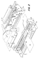
- the on-demand multicolor printing apparatus 20 of the present invention is formed from a housing 22 having two different print stations 24, 26 therein.
- the print stations 24, 26 are operatively coupled together to print indicia 28, such as text, images, graphics and the like, on a print medium 30, such as a label, ticket, tag and the like.
- the indicia 28 may be monochrome or multicolored.
- Print station 24 is a thermal transfer print station and print station 26 is an ink jet print station.
- Each of the print stations 24, 26 are mounted to and within the housing 22 by suitable means. It is to be noted that the housing 22 is only partially shown in the drawings and one of ordinary skill would realize that the print stations 24, 26 are enclosed within the housing 22.
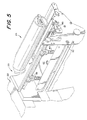
- the thermal transfer print station 24 is most clearly illustrated in FIGURES 4 and 5.
- the thermal transfer print station 24 is used to print indicia of a single monochromatic color on the print medium 30, for example the color black.
- the thermal transfer print station 24 includes a driving mechanism which is formed from a platen roller 32, driven by a stepper motor 60 through a belt and pulley drive assembly 34, 36, 38 to advance the print medium 30 therethrough in a conventional manner.
- the thermal transfer print station 24 further includes a thermal printhead assembly 40.
- the thermal printhead assembly 40 includes a conventional thermal transfer printhead 42 having a line of heater elements 44, such printhead 42 being positioned by a pivot 46 such that heater elements 44 are aligned transverse to the motion of the print medium 30. Heater elements 44 are pressed against the print medium 30 and the print medium 30 against platen roller 32 by the action of a bias mechanism 48 which also forms part of the thermal printhead assembly 40.
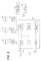
- FIGURE 3 is a block diagram of a controller 50 for both the thermal transfer print station 24 and the ink jet print station 26.
- the controller 50 includes a microprocessor system 52 comprised of one or more integrated circuits having internal program memory, random access memory, a serial port responsive to a serial data input 54 for the receipt of information to be printed on the print medium 30, and input and output ports interconnected and operating in a manner well known in the art.
- the controller 50 When information to be printed on the print medium 30 is transmitted to the serial data input 54 as a signal and when a signal is received by the controller 50 calling for a label, tag or ticket to be printed by the printing apparatus 20, the controller 50 begins pulsing line 56 to motor driver 58 in order to advance stepper motor 60. The rate in which the stepper motor 60 is pulsed is dependent on a number of factors that will be described hereinafter.
- Microprocessor system 52 then loads into thermal transfer printhead 42 image data representing selected heater elements 44 to be energized. Microprocessor 52 then energizes the selected heater element 44 by pulsing the thermal transfer printhead 42 to print a first row of dots.
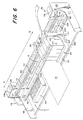
- the ink jet print station 26 is most clearly illustrated in FIGURE 6.
- the ink jet print station 26 is used to print indicia of a plurality of monochromatic colors or of a single monochromatic color.
- the plurality of monochromatic colors or the single monochromatic color which are printed by the ink jet print station 26 is different than the monochromatic colored indicia printed by the thermal transfer print station 24.
- a carriage 62 carrying an ink jet printhead assembly 64 thereon is supported on guide shafts 66 for sliding movement in the axial direction thereof.
- the guide shafts 66 are fixedly mounted to a frame 68.
- a timing belt 70 is coupled to the carriage 62 and extends between a pair of pulleys 72, 74, one of which, pulley 74, is coupled to an output shaft 76 of a carriage stepper motor 78.
- stepper motor 78 is driven by motor driver 80 which is selectively pulsed by the microprocessor system 52 through line 82.
- the rotation of the carriage stepper motor 78 causes, through a transmission mechanism provided by the pulleys 72, 74 and the timing belt 70, the carriage 62 to slide reversibly on the guide shafts 66 in the direction of arrow A or B in FIGURE 6 across the print medium 30.
- Each movement of the carriage 62 in direction A or B is referred to as a "primary scan".
- the reference position of the carriage 62 is detected by a home sensor 84 and associated flag 86.
- a linear encoder strip 88 is coupled to a linear encoder sensor (not shown) operatively placed on the carriage 62 for feedback of carriage movement by the carriage stepper motor 78.
- the output of the home sensor 84 is fed into controller 50 through line 90 and the output of the linear encoder sensor 88 is fed into controller 50 through line 92 for processing of carriage position information by controller 50.
- the ink jet printhead assembly 64 may be of any one of various liquid or solid jet types including thermal ink jet or piezo-electric ink jet.
- the ink jet printhead assembly 64 is of the disposable thermal ink jet type and is comprised of four separate and individually replaceable modules 94, 96, 98, 100 which are mounted on the carriage 62.
- Module 94 is filled with cyan ink
- module 96 is filled with magenta ink
- module 98 is filled with yellow ink
- module 100 is filled with black ink.
- Cyan, magenta, yellow and black ink are the commonly used colors when printing using subtractive color printing algorithms which are well known in the art and therefore, are not described herein.
- Each module 94, 96, 98, 100 is formed from a plurality of nozzles (not shown) for ejecting ink on the print medium 30 when energized by heat, electric charge or acoustic waves depending on the printhead technology being used.
- Each of the nozzles in-each module 94, 96, 98, 100 are equally spaced along an axis transverse to the axis of the primary scan. The distance along the transverse axis between the first position 102 of the nozzles and last position 104 of the nozzles along each printhead module 94, 96, 98, 100 is known hereinafter as the ink jet printhead's "swath.”
- a second stepper motor 106 is coupled to an advancement roller 108 through gear set 110.
- the advancement roller 108 is spring loaded against bias rollers 112 for driving the print medium 30 therethrough in response to pulses on line 114 from microprocessor system 52 which causes rotation of the second stepper motor 106 using motor driver 107.
- the movement of the print medium 30 through rollers 108, 112 is referred to as a "secondary scan".
- the ink jet printhead assembly 64 is driven in response to an input signal from line 118 from the microprocessor system 25, whereby colored indicia 28 is printed on the print medium 30.
- the print medium 30 must be absolutely stationary as the primary scan is in progress, therefore, a primary scan and a secondary scan cannot occur simultaneously.
- a secondary scan takes place to advance the print medium 30 to the next print position.
- the next print position is determined by the quality of printing desired.
- the secondary scan advancement length is the swath of the ink jet printhead assembly 64.
- high quality mode interleaved dot row printing is used requiring the secondary scan advancement length to be a sublength of the swath width of the ink jet printhead assembly 64, as is well know in the art of ink jet printing.
- the controller 50 moves the carriage 62 over to maintenance and capping station 120 to purge and wipe the ink jet printhead assembly 64 to ensure that the printhead nozzles are free of foreign debris.
- the controller 50 moves the carriage 62 over to the maintenance and capping station 120 to cap the ink jet printhead assembly 64 for preventing ink stored in the ink jet printhead assembly 64 from drying and clogging the printhead nozzles.
- An important feature of this invention is to print indicia 28 on the print medium 30 using both the thermal transfer print station 24 and the ink jet print station 26. Combining both types of print stations 24, 26 is new in the art of on-demand color printers and complex since the advancement profiles of the print medium 30 through each type of print station 24, 26 differs.
- the velocity of the print medium 30 through the thermal transfer print station 24 needs to be continuous.
- the velocity profile of the print medium 30 through the ink jet print station 26 is noncontinuous because the print medium 30 is required to be stationary during each primary scan. Therefore, a problem is created because the motion of the print medium 30 needs to be altered between the thermal transfer print station 24 and the ink jet print station 26.
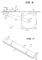
- FIGURE 7 illustrates the decoupling station 122 in the preferred embodiment.
- the decoupling station 122 is formed from a pair of flanges 124, 126 which are placed at an angle relative to each other.
- the decoupling station 122 is preferably mounted on the housing 22, but may be mounted on either the thermal transfer print station 24 or the ink jet print station 26 by suitable struts.
- An inlet port 128 is formed between the ends of the flanges 124, 126 which are farthest apart from each other and an exit port is formed between the ends of the flanges 124, 126 which are closest to each other. This allows the print medium 30 to pass therethrough.
- the print medium 30 is advanced through the thermal transfer print station 24 under continuous motion and printed on in a single monochrome color by the thermal transfer printhead 42 as described hereinabove.
- the decoupling station 122 receives the print medium 30 through inlet port 128 and allows the print medium 130 to advance until the print medium 30 exits the decoupling station 122 through exit port 130 and contacts the advancement roller 108 of the ink jet print station 26.
- the contact of the print medium 30 with the advancement roller 108 is detected by a web sensor 132.
- An accumulation sensor 134 is operatively placed within decoupling station 122 to detect the amount of print medium 30 collected within the decoupling station 122.
- accumulation sensor 134 is of the acoustic type, however, other types of sensors may be used such as optical or mechanical.
- the thermal transfer print station 24 continues to advance the print medium 30 until at least one ink jet printhead-swath width plus the distance between exit port 130 of the decoupling station 122 and the last position 104 of the ink jet printhead nozzles has accumulated in the decoupling station 122 as detected by accumulation sensor 134.
- the print medium 30 accumulates between flanges 124, 126.
- the ink jet print station 26 performs a secondary scan of sufficient length to position the print medium 30 underneath the ink jet printhead assembly 64, where a primary scan is performed and printing commences. As the process is performed, the thermal transfer print station 24 continues to advance the print medium 30 into decoupling station 122.
- the ink jet print station 26 initiates another secondary scan to reposition the print medium 30 underneath the ink jet printhead assembly 64, but only after at least one ink jet printhead swath of the print medium 30 has accumulated in decoupling station 122 to prevent the ink jet print station 26 from exerting tension on the print medium 30 which may cause misregistering of the print medium 30 in the thermal transfer print station 24.
- thermal transfer print station 24 continues until the entire thermal transfer indicia is printed on the print medium 30 by the thermal transfer print station 24.
- the ink jet print station 26 finishes printing the appropriate indicia 28 on the print medium 30.
- the thermal transfer print station 24 continues to advance the print medium 30, without printing on it, through the decoupling station 122, as described above, until the entire print medium 30 has passed through the printing apparatus 20 and been printed on by the ink jet print station 26.
- the speed of the print medium 30 exiting the thermal transfer print station 24 is regulated by a control system (not shown) within the controller 50 using the quantity of the print medium 30 accumulation in the decoupling station 122 as an input and the angular velocity of the stepper motor 60 of the thermal transfer print station 24 as an output.
- the angular velocity of the stepper motor 60 is inversely proportional to the level of the print medium accumulation in the decoupling station 122 so that when a minimum amount of the print medium 30 is stored in the decoupling station 122, the angular velocity of the thermal transfer print station stepper motor 60 is at a maximum and vice versa.
- This control system works to keep the decoupling station 122 filled with the print medium 30 so that the ink jet print station 26 may run at maximum speed. It should be appreciated that other control systems external to controller 50 may alternatively be used to control the advancement rate of the print medium 30 into the decoupling station 122 such as PID control means among others.
- the print medium 30 may be cut by a cutting module (not shown) placed downstream from ink jet print station 26 or may be torn off by the user on a tear bar 136.
- the cutting operation is controlled by the controller 50 through its output port (not shown) and the cutting or tearing operating is detected by a sensor 138, operatively placed near the cutting module or the tear bar 136 as best seen in FIGURE 1.
- the sensor 138 is connected to the controller 50 through line 140.
- the print medium 30 is advanced in a reverse direction so that the newly created leading edge on the print medium 30 just created by the cut or tear operation is positioned underneath the thermal printhead 42 of the thermal transfer print station 24 in anticipation of receipt by the controller 50 of new indicia to be printed onto the print medium 30.
- An optional cutter blade 137 may be placed on the carriage 62 to selectively cut the print medium 30 or, in the case of a label 142, to selectively die cut the label 142.
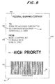
- FIGURE 8 showing a typical label 142 that could be printed by this new printing apparatus 20.
- fields 144, 146, 148, 150 are desired to be printed in black ink and field 152 is desired to be printed in red ink to highlight the fact that the package that this label 142 is identifying has a high shipping priority.
- fields 144, 146, 148 are printed in black ink and field 150, the barcode, should be printed at the highest possible print quality to increase its machine readability, these fields are rendered and transmitted by the controller 50 to the thermal transfer print station 24 for rapid and high quality printing. Because field 152 is printed in the color of red, controller 50 renders and transmits the bitmap image of field 152 to the ink jet print station 26 for printing in red ink.
- the printing time of label 142 is quite fast because little time is required by the ink jet print station 26 to print field 152 in color.
- the label 142 is rapidly printed by the thermal transfer print station 24 and rapidly advanced through the ink jet print station 26, via the decoupling station 122, until the location of field 152 is placed within the swath underneath the ink jet printhead assembly 64 where the field 152 is printed. Immediately after field 152 is printed, the label 142 continues to rapidly advance in the manner described hereinabove until the label 142 exits the ink jet print station 26.
- the entire label 142 could be printed by the thermal transfer print station 24.
- the label 142 is quickly printed by the thermal transfer print station 24 and rapidly advanced through the decoupling station 122 and the ink jet print station 26 until the label 142 exits the ink jet print station 26.
- the high print speed that thermal transfer printing affords is not compromised when indicia which is to be printed by the ink jet print station 26 is not printed on the print medium 30.
- the printing apparatus 20 of the present invention is efficient and is environmentally friendly when printing multicolor indicia on the print medium 30 because only one thermal transfer ribbon is required and the ink jet print station 26 only deposits ink on the print medium 30 where required when printing multicolored indicia.
- prior art thermal transfer ribbon saving techniques may be used on the thermal transfer print station 24.
- the printing apparatus 20 of the present invention can be manufactured at a substantially lower cost than existing on-demand multicolor printers that incorporate more than two thermal transfer printheads, while allowing for a much larger gamut of colors to be printed.
- the printing apparatus 20 of the present invention can be manufactured at a substantially lower cost than existing on-demand multicolor printers that incorporate more than two stationary ink jet printheads, while allowing for a much larger gamut of colors to be printed.
- an optical or magnetic scanner module 154 can be placed on the carriage 62 of the ink jet print station 26 to capture the optical or magnetic image of the print medium 30 as the carriage 62 of the ink jet print station 26 traverses the print medium 30. This optical or magnetic image may be transmitted to the controller 50 for verifying that machine readable symbols or other critical indicia have been printed by either the thermal transfer print station 24 or the ink jet print station 26.
- the cutter module could be placed between the thermal transfer print station 24 and the ink jet print station 26. Alteratively, the positions of the thermal transfer print station 24 and the ink jet print station 26 could be reversed.
Description
- This application is based on and claims the priority of provisional application Serial No. 60/070,809 filed on January 8, 1998.
- The present invention is generally directed to a novel on-demand printing apparatus capable of printing indicia, such as bar codes, text, graphics and the like, on a print medium, such as labels, tags, tickets and the like.
- On-demand multicolor printers are well known in the prior art and are used in many applications to imprint a continuous print medium such as labels, tags and tickets. These applications include bar code printers, ticket printers and garment tag printers. In such printers, the print medium is conveyed through a print station and indicia is printed thereon as the print medium passes a printhead. printhead.
- Such printing may be performed by a variety of printing techniques, such as impact, ink jet, laser, and thermal transfer printing. At the time of this disclosure, thermal transfer printing is the most widely used printing technology.
- In a thermal transfer printing process, a thermally reactive ribbon is disposed between a thermal printhead and the print medium. The thermal printhead has a plurality of heating elements thereon that can be selectively energized. As the thermally reactive ribbon is heated, ink is transferred from the ribbon onto the print-medium forming-indicia thereon.
- To print color, a plurality of thermal transfer print stations are concatenated together, as described in United States Patent No. 5,675,369, wherein each thermal transfer print station contains a stationary printhead having a width at least as wide as the print medium being printed on. Each thermal transfer print station is actuatable for applying a monochromatic image to the print medium. The monochromatic image printed by each print station can be kept either separate or mixed together on the print medium allowing for a large gamut of colors to be printed on the print medium.
- Ink jet printing utilizes a printhead having a plurality of ejection nozzles for ejecting ink onto a print medium to form indicia thereon. A prior art bubble jet printer manufactured by Canon®, which is similar to the color printer described in United States Patent No. 5,675,360, replaces each thermal transfer print station with an ink jet print station. Each ink jet print station contains a stationary printhead having the approximate width of the print medium being imaged as well.as associated printhead maintenance hardware and electronics.
- There are advantages and disadvantages to each of two technologies listed above.
- Thermal transfer printing technology generally yields the highest quality image especially when printing machine readable symbologies, such as bar codes. Thermal transfer technology also yields highly durable images, prints very fast, and is robust for harsh industrial printing environments.
- Unfortunately, thermal transfer technology is extremely wasteful of ribbons, costly to run, and poor for the environment when printing multiple colors due to ribbon wastage. Ribbon saving means incorporated in these printers helps to decrease the amount of wasted ribbon however, depending on the format of the printed indica, prior art ribbon saving techniques may not be very effective. In addition, incorporating multiple thermal transfer print stations in a printer is very costly and, likewise, renders these types of printers much more expensive then their monochromatic counterparts that only require one thermal transfer print station.
- Ink jet printing technology has the key advantage of efficiency. Ink jet printheads consume less power than thermal transfer printheads and only spray ink where required, eliminating generation of wasted ribbons and ink. Print speeds of printers incorporating stationary ink jet printheads, such as the Canon® printer described before, are approximately the same as thermal transfer printers, although, at least theoretically, the ink jet printers can print at much higher speeds.
- The disadvantages of using ink jet technology in on-demand printers is the reliability of the printheads and poor print quality. Most notably, print quality is much lower on printers incorporating stationary ink jet printheads since deviations in ink jet nozzle directionality causes striations in the printed image. Striations may also be caused by clogged or damaged nozzles that will not eject droplets of ink when energized. Inoperative nozzles are especially detrimental when printing machine readable symbologies such as horizontally oriented bar codes since bar and space widths may be inadvertently altered.
- The limitations of ink jet technology in on-demand printers described heretofore can be eliminated by using a disposable scanning ink jet printhead and interleaving algorithms which are well known in the art and described in United States Patent No. 5,686,944. Such disposable scanning ink jet printhead, in a preferred embodiment, may have an ink reservoir thereon. Using a disposable ink jet printhead reduces the risk of printhead damage and increases printer robustness because the printheads can be periodically and inexpensively replaced before or immediately after damage to the printhead. A disadvantage to scanning ink jet printheads is the resulting reduction in print speed which limits their use in on-demand printing applications.
- The multicolored printers discussed above have not been well accepted by consumers primarily because of excessive equipment costs in both the thermal transfer and ink jet printer types, consumables costs in the case of thermal transfer printers, and low print quality and reliability in the case of stationary ink jet printers.
- For the foregoing reasons, an on-demand color printing apparatus is needed that can be manufactured at a low cost; leverages the quality and durability of thermal transfer printing when printing machine readable symbologies and other critical indicia; leverages the high print speed of thermal transfer printing when only monochrome thermal transfer printing is required; leverages the print quality and reliability of ink jet printing using scanning ink jet printheads; and has the efficiency and environmental friendliness of ink jet technology for printing multicolored indicia when desired on a print medium without causing a major reduction in print speed for most image formats. The present invention provides such a novel printing apparatus which presents these features and advantages and which overcomes the problems in the prior art. These will become apparent upon a reading of the attached specification in combination with an examination of the drawings.
- In EP-A-0782929, is described a printing apparatus for printing indicia on a medium having a housing, said printing apparatus being characterised by: a thermal transfer printhead assembly mounted in said housing for printing a monochrome colored indicia on the medium; and an ink jet printhead assembly mounted in said housing for printing at least one monochrome colored indicia on the medium. A method of printing indicia on a medium using a printing apparatus is also described.
- It is a general object of the present invention to provide a novel and improved on-demand color printing apparatus which avoids the disadvantages of prior printers while affording additional structural and operating advantages.
- Another general object of the present invention is to provide a novel printing apparatus which prints indicia on a print medium at a low cost, using a mixture of thermal transfer printing and ink jet printing.
- An object of the present invention is to provide a novel printing apparatus-which prints multicolored indicia on a print medium using a mixture of thermal transfer printing and ink jet printing without wasting excessive amounts of ribbon.
- Another object of the present invention is to provide a novel printing apparatus which provides high speed monochrome printing on a print medium using thermal transfer printing only when multicolored indicia are not desired to be printed on the print medium.
- It is a further object of the present invention to provide a novel printing apparatus which prints monochrome indicia on a print medium using thermal transfer printing and which prints a plurality of monochrome colored indicia on the print medium by using ink jet printing without causing a major reduction in print speed for most image formats.
- It is an even further object of the present invention to provide a low cost and reliable printing apparatus for producing, on-demand, multicolor print images on a print medium using a thermal print station and an ink jet print station in a cooperating relationship that cooperatively render images on the print medium.
- A printing apparatus, in accordance with one aspect of the invention, is defined in Claim 1, with preferred or optional features defined in the appended sub-claims.
- A method of printing, in accordance with another aspect of the invention, is defined in Claim 13, with preferred or optional features defined in the appended sub-claims.
- The organization and manner of the structure and operation of the invention, together with further objects and advantages thereof, may best be understood by reference to the following description, taken in connection with the accompanying drawings, wherein like reference numerals identify like elements in which:
- FIGURE 1 is a partial perspective view of an on-demand multicolor printing apparatus which incorporates the features of the present invention;
- FIGURE 2 is an partially exploded perspective view, shown partially, of the on-demand multicolor printing apparatus shown in FIGURE 1;
- FIGURE 3 is a partially schematic and partially functional block diagram of a microprocessor-based controller for the on-demand multicolor printing apparatus shown in FIGURE 1;
- FIGURE 4 is a side elevational view of a thermal transfer print station which forms part of the printing apparatus shown in FIGURE 1;
- FIGURE 5 is a perspective view, shown partially, of the thermal transfer print station attached to the printing apparatus housing;
- FIGURE 6 is a perspective view of an ink jet print station which forms part of the printing apparatus shown in FIGURE 1;
- FIGURE 7 is a perspective view of a decoupling station which forms part of the printing apparatus shown in FIGURE 1; and
- FIGURE 8 is a top plan view of a label printed by the multicolor printing apparatus of the present invention.
-
- While the invention may be susceptible to embodiment in different forms, there is shown in the drawings, and herein will be described in detail, a specific embodiment with the understanding that the present disclosure is to be considered an exemplification of the principles of the invention, and is not intended to limit the invention to that as illustrated and described herein.
- The on-demand
multicolor printing apparatus 20 of the present invention is formed from ahousing 22 having twodifferent print stations print stations indicia 28, such as text, images, graphics and the like, on aprint medium 30, such as a label, ticket, tag and the like. Theindicia 28 may be monochrome or multicolored.Print station 24 is a thermal transfer print station andprint station 26 is an ink jet print station. Each of theprint stations housing 22 by suitable means. It is to be noted that thehousing 22 is only partially shown in the drawings and one of ordinary skill would realize that theprint stations housing 22. - The thermal
transfer print station 24 is most clearly illustrated in FIGURES 4 and 5. The thermaltransfer print station 24 is used to print indicia of a single monochromatic color on theprint medium 30, for example the color black. The thermaltransfer print station 24 includes a driving mechanism which is formed from aplaten roller 32, driven by astepper motor 60 through a belt andpulley drive assembly print medium 30 therethrough in a conventional manner. The thermaltransfer print station 24 further includes athermal printhead assembly 40. Thethermal printhead assembly 40 includes a conventionalthermal transfer printhead 42 having a line ofheater elements 44,such printhead 42 being positioned by apivot 46 such thatheater elements 44 are aligned transverse to the motion of theprint medium 30.Heater elements 44 are pressed against theprint medium 30 and theprint medium 30 againstplaten roller 32 by the action of abias mechanism 48 which also forms part of thethermal printhead assembly 40. - FIGURE 3 is a block diagram of a
controller 50 for both the thermaltransfer print station 24 and the inkjet print station 26. Thecontroller 50 includes amicroprocessor system 52 comprised of one or more integrated circuits having internal program memory, random access memory, a serial port responsive to aserial data input 54 for the receipt of information to be printed on theprint medium 30, and input and output ports interconnected and operating in a manner well known in the art. - When information to be printed on the
print medium 30 is transmitted to theserial data input 54 as a signal and when a signal is received by thecontroller 50 calling for a label, tag or ticket to be printed by theprinting apparatus 20, thecontroller 50 begins pulsingline 56 tomotor driver 58 in order to advancestepper motor 60. The rate in which thestepper motor 60 is pulsed is dependent on a number of factors that will be described hereinafter.Microprocessor system 52 then loads intothermal transfer printhead 42 image data representing selectedheater elements 44 to be energized.Microprocessor 52 then energizes the selectedheater element 44 by pulsing thethermal transfer printhead 42 to print a first row of dots. It then pulses line 56 tomotor driver 58 again to advancestepper motor 60 by one dot row, thereby causingplaten roller 32 to advance theprint medium 30 in a conventional manner, and then repeats the printing process. This process continues until all of the information to be printed by the thermaltransfer print station 24 on theprint medium 30 has been completed, at whichtime controller 50 ceases printing and awaits the request for the next indicia to be printed. - The ink
jet print station 26 is most clearly illustrated in FIGURE 6. The inkjet print station 26 is used to print indicia of a plurality of monochromatic colors or of a single monochromatic color. Preferably, the plurality of monochromatic colors or the single monochromatic color which are printed by the inkjet print station 26 is different than the monochromatic colored indicia printed by the thermaltransfer print station 24. At times, however, it may be necessary for the inkjet print station 26 to print indicia that is the same monochromatic color as printed by the thermaltransfer print station 24. This is normally required when the alignment between two different colored indicia on theprint medium 30 is critical and where the color of one of the indicias is the same color as the color being printed by the thermaltransfer print station 24. This action is required because the registration between the thermaltransfer print station 24 and the inkjet print station 26 may not be exactly aligned and, furthermore, the printing resolutions of bothprint stations print stations jet print station 26 to print the differently colored indicias to ensure perfect alignment. - A
carriage 62 carrying an inkjet printhead assembly 64 thereon is supported onguide shafts 66 for sliding movement in the axial direction thereof. Theguide shafts 66 are fixedly mounted to aframe 68. Atiming belt 70 is coupled to thecarriage 62 and extends between a pair ofpulleys 72, 74, one of which, pulley 74, is coupled to anoutput shaft 76 of acarriage stepper motor 78. As seen in FIGURE 3,stepper motor 78 is driven bymotor driver 80 which is selectively pulsed by themicroprocessor system 52 throughline 82. - In FIGURE 6, the rotation of the
carriage stepper motor 78 causes, through a transmission mechanism provided by thepulleys 72, 74 and thetiming belt 70, thecarriage 62 to slide reversibly on theguide shafts 66 in the direction of arrow A or B in FIGURE 6 across theprint medium 30. Each movement of thecarriage 62 in direction A or B is referred to as a "primary scan". - The reference position of the
carriage 62 is detected by ahome sensor 84 and associatedflag 86. In addition, a linear encoder strip 88 is coupled to a linear encoder sensor (not shown) operatively placed on thecarriage 62 for feedback of carriage movement by thecarriage stepper motor 78. As shown in FIGURE 3, the output of thehome sensor 84 is fed intocontroller 50 throughline 90 and the output of the linear encoder sensor 88 is fed intocontroller 50 throughline 92 for processing of carriage position information bycontroller 50. - The ink
jet printhead assembly 64 may be of any one of various liquid or solid jet types including thermal ink jet or piezo-electric ink jet. In the preferred embodiment, the inkjet printhead assembly 64 is of the disposable thermal ink jet type and is comprised of four separate and individuallyreplaceable modules carriage 62.Module 94 is filled with cyan ink;module 96 is filled with magenta ink;module 98 is filled with yellow ink; andmodule 100 is filled with black ink. Cyan, magenta, yellow and black ink are the commonly used colors when printing using subtractive color printing algorithms which are well known in the art and therefore, are not described herein. - Each
module print medium 30 when energized by heat, electric charge or acoustic waves depending on the printhead technology being used. Each of the nozzles in-eachmodule first position 102 of the nozzles andlast position 104 of the nozzles along eachprinthead module - In the ink
jet print station 26, asecond stepper motor 106 is coupled to anadvancement roller 108 throughgear set 110. Theadvancement roller 108 is spring loaded againstbias rollers 112 for driving theprint medium 30 therethrough in response to pulses online 114 frommicroprocessor system 52 which causes rotation of thesecond stepper motor 106 usingmotor driver 107. The movement of theprint medium 30 throughrollers - While the
carriage 62 moves once in the direction A or B, the inkjet printhead assembly 64 is driven in response to an input signal fromline 118 from the microprocessor system 25, wherebycolored indicia 28 is printed on theprint medium 30. In this embodiment, theprint medium 30 must be absolutely stationary as the primary scan is in progress, therefore, a primary scan and a secondary scan cannot occur simultaneously. - After each primary-scan, a secondary scan takes place to advance the
print medium 30 to the next print position. The next print position is determined by the quality of printing desired. In low quality mode, the secondary scan advancement length is the swath of the inkjet printhead assembly 64. In high quality mode, interleaved dot row printing is used requiring the secondary scan advancement length to be a sublength of the swath width of the inkjet printhead assembly 64, as is well know in the art of ink jet printing. - This process continues until all of the information to be printed on the
print medium 30 has been completed, at which time thecontroller 50 ceases printing and awaits the request for the next ink jet image to be printed. - Periodically, the
controller 50 moves thecarriage 62 over to maintenance andcapping station 120 to purge and wipe the inkjet printhead assembly 64 to ensure that the printhead nozzles are free of foreign debris. When the inkjet print station 26 is not printing, thecontroller 50 moves thecarriage 62 over to the maintenance andcapping station 120 to cap the inkjet printhead assembly 64 for preventing ink stored in the inkjet printhead assembly 64 from drying and clogging the printhead nozzles. - An important feature of this invention is to print
indicia 28 on theprint medium 30 using both the thermaltransfer print station 24 and the inkjet print station 26. Combining both types ofprint stations print medium 30 through each type ofprint station - To achieve optimal print quality in a thermal transfer printing, the velocity of the
print medium 30 through the thermaltransfer print station 24 needs to be continuous. In contrast, the velocity profile of theprint medium 30 through the inkjet print station 26 is noncontinuous because theprint medium 30 is required to be stationary during each primary scan. Therefore, a problem is created because the motion of theprint medium 30 needs to be altered between the thermaltransfer print station 24 and the inkjet print station 26. - To solve this problem, a decoupling of the motion between the thermal
transfer print station 24 and the inkjet print station 26 is provided in the present invention, as best shown in FIGURE 2 by using adecoupling station 122. FIGURE 7 illustrates thedecoupling station 122 in the preferred embodiment. - The
decoupling station 122 is formed from a pair offlanges decoupling station 122 is preferably mounted on thehousing 22, but may be mounted on either the thermaltransfer print station 24 or the inkjet print station 26 by suitable struts. Aninlet port 128 is formed between the ends of theflanges flanges print medium 30 to pass therethrough. - In operation, the
print medium 30 is advanced through the thermaltransfer print station 24 under continuous motion and printed on in a single monochrome color by thethermal transfer printhead 42 as described hereinabove. Thedecoupling station 122 receives theprint medium 30 throughinlet port 128 and allows theprint medium 130 to advance until theprint medium 30 exits thedecoupling station 122 throughexit port 130 and contacts theadvancement roller 108 of the inkjet print station 26. The contact of theprint medium 30 with theadvancement roller 108 is detected by aweb sensor 132. Anaccumulation sensor 134 is operatively placed withindecoupling station 122 to detect the amount ofprint medium 30 collected within thedecoupling station 122. In the preferred embodiment,accumulation sensor 134 is of the acoustic type, however, other types of sensors may be used such as optical or mechanical. - The thermal
transfer print station 24 continues to advance theprint medium 30 until at least one ink jet printhead-swath width plus the distance betweenexit port 130 of thedecoupling station 122 and thelast position 104 of the ink jet printhead nozzles has accumulated in thedecoupling station 122 as detected byaccumulation sensor 134. Theprint medium 30 accumulates betweenflanges decoupling station 122, the inkjet print station 26 performs a secondary scan of sufficient length to position theprint medium 30 underneath the inkjet printhead assembly 64, where a primary scan is performed and printing commences. As the process is performed, the thermaltransfer print station 24 continues to advance theprint medium 30 intodecoupling station 122. - When the primary scan is completed, the ink
jet print station 26 initiates another secondary scan to reposition theprint medium 30 underneath the inkjet printhead assembly 64, but only after at least one ink jet printhead swath of theprint medium 30 has accumulated indecoupling station 122 to prevent the inkjet print station 26 from exerting tension on theprint medium 30 which may cause misregistering of theprint medium 30 in the thermaltransfer print station 24. - This process continues until the entire thermal transfer indicia is printed on the
print medium 30 by the thermaltransfer print station 24. When this occurs, the inkjet print station 26 finishes printing theappropriate indicia 28 on theprint medium 30. To complete the printing process, the thermaltransfer print station 24 continues to advance theprint medium 30, without printing on it, through thedecoupling station 122, as described above, until theentire print medium 30 has passed through theprinting apparatus 20 and been printed on by the inkjet print station 26. - The speed of the
print medium 30 exiting the thermaltransfer print station 24 is regulated by a control system (not shown) within thecontroller 50 using the quantity of theprint medium 30 accumulation in thedecoupling station 122 as an input and the angular velocity of thestepper motor 60 of the thermaltransfer print station 24 as an output. In the preferred embodiment, the angular velocity of thestepper motor 60 is inversely proportional to the level of the print medium accumulation in thedecoupling station 122 so that when a minimum amount of theprint medium 30 is stored in thedecoupling station 122, the angular velocity of the thermal transfer printstation stepper motor 60 is at a maximum and vice versa. This control system works to keep thedecoupling station 122 filled with theprint medium 30 so that the inkjet print station 26 may run at maximum speed. It should be appreciated that other control systems external tocontroller 50 may alternatively be used to control the advancement rate of theprint medium 30 into thedecoupling station 122 such as PID control means among others. - After the
print medium 30 has traversed both the thermaltransfer print station 24 and the inkjet print station 26, theprint medium 30 may be cut by a cutting module (not shown) placed downstream from inkjet print station 26 or may be torn off by the user on atear bar 136. The cutting operation is controlled by thecontroller 50 through its output port (not shown) and the cutting or tearing operating is detected by asensor 138, operatively placed near the cutting module or thetear bar 136 as best seen in FIGURE 1. Thesensor 138 is connected to thecontroller 50 throughline 140. When the cut or tear is detected by thecontroller 50, theprint medium 30 is advanced in a reverse direction so that the newly created leading edge on theprint medium 30 just created by the cut or tear operation is positioned underneath thethermal printhead 42 of the thermaltransfer print station 24 in anticipation of receipt by thecontroller 50 of new indicia to be printed onto theprint medium 30. Anoptional cutter blade 137 may be placed on thecarriage 62 to selectively cut theprint medium 30 or, in the case of alabel 142, to selectively die cut thelabel 142. - The advantages to this invention may be best appreciated by referencing FIGURE 8 showing a
typical label 142 that could be printed by thisnew printing apparatus 20. In the following example, fields 144, 146, 148, 150 are desired to be printed in black ink andfield 152 is desired to be printed in red ink to highlight the fact that the package that thislabel 142 is identifying has a high shipping priority. - Because
fields field 150, the barcode, should be printed at the highest possible print quality to increase its machine readability, these fields are rendered and transmitted by thecontroller 50 to the thermaltransfer print station 24 for rapid and high quality printing. Becausefield 152 is printed in the color of red,controller 50 renders and transmits the bitmap image offield 152 to the inkjet print station 26 for printing in red ink. - The printing time of
label 142 is quite fast because little time is required by the inkjet print station 26 to printfield 152 in color. Thelabel 142 is rapidly printed by the thermaltransfer print station 24 and rapidly advanced through the inkjet print station 26, via thedecoupling station 122, until the location offield 152 is placed within the swath underneath the inkjet printhead assembly 64 where thefield 152 is printed. Immediately afterfield 152 is printed, thelabel 142 continues to rapidly advance in the manner described hereinabove until thelabel 142 exits the inkjet print station 26. - If the
label 142 does not contain indicia which is to be printed by the inkjet print station 26, theentire label 142 could be printed by the thermaltransfer print station 24. In this example, thelabel 142 is quickly printed by the thermaltransfer print station 24 and rapidly advanced through thedecoupling station 122 and the inkjet print station 26 until thelabel 142 exits the inkjet print station 26. In this case, the high print speed that thermal transfer printing affords is not compromised when indicia which is to be printed by the inkjet print station 26 is not printed on theprint medium 30. - It should be appreciated that the
printing apparatus 20 of the present invention is efficient and is environmentally friendly when printing multicolor indicia on theprint medium 30 because only one thermal transfer ribbon is required and the inkjet print station 26 only deposits ink on theprint medium 30 where required when printing multicolored indicia. To decrease the amount of ribbon wastage, prior art thermal transfer ribbon saving techniques may be used on the thermaltransfer print station 24. - It should further be appreciated that the
printing apparatus 20 of the present invention can be manufactured at a substantially lower cost than existing on-demand multicolor printers that incorporate more than two thermal transfer printheads, while allowing for a much larger gamut of colors to be printed. In addition, theprinting apparatus 20 of the present invention can be manufactured at a substantially lower cost than existing on-demand multicolor printers that incorporate more than two stationary ink jet printheads, while allowing for a much larger gamut of colors to be printed. - It should also be appreciated that an optical or
magnetic scanner module 154 can be placed on thecarriage 62 of the inkjet print station 26 to capture the optical or magnetic image of theprint medium 30 as thecarriage 62 of the inkjet print station 26 traverses theprint medium 30. This optical or magnetic image may be transmitted to thecontroller 50 for verifying that machine readable symbols or other critical indicia have been printed by either the thermaltransfer print station 24 or the inkjet print station 26. - It should also be appreciated that other orientations of the
multicolor printing apparatus 20 of the present invention could be achieved. For example, the cutter module could be placed between the thermaltransfer print station 24 and the inkjet print station 26. Alteratively, the positions of the thermaltransfer print station 24 and the inkjet print station 26 could be reversed. - While a preferred embodiment of the present invention is shown and described, it is envisioned that those skilled in the art may devise various modifications of the present invention without departing from the scope of the appended claims.
Claims (25)
- A printing apparatus (20) for printing indicia (28) on a medium (30) having a housing (22), a thermal transfer printhead assembly (40) mounted in said housing (22) for printing a monochrome colored indicia on the medium (30); and an ink jet printhead assembly (64) mounted in said housing (30) for printing at least one monochrome colored indicia on the medium (30), said printing apparatus (20) being characterized by: decoupling means (122) mounted between said thermal transfer printhead assembly (40) and said ink jet printhead assembly (64) for accumulating medium (30) therein, and by a sensor (134) associated with said decoupling means (122) for sensing a predetermined level of medium (30) accumulated in said decoupling means (122).
- A printing apparatus (20) as defined in claim 1, being characterized in that said monochrome colored indicia printed by said inkjet printhead assembly (64) is different in color than said monochrome colored indicia printed by said thermal transfer printhead assembly (40).
- A printing apparatus (20) as defined in claim 1, being characterized in that said ink jet printhead assembly (64) is used for printing a plurality of monochrome colored indicia on the medium (30), each of which are different in color than said monochrome colored indicia printed by said thermal transfer printhead assembly (40).
- A printing apparatus (20) as defined in claim 1, being characterized in that said ink jet printhead assembly (64) is used for printing a plurality of monochrome colored indicia on the medium (30), one of which is the same in color as said monochrome colored indicia printed by said thermal transfer printhead assembly (40).
- A printing apparatus (20) as defined in claim 1, being characterized in that said decoupling means (122) has a pair of flanges (124, 126) being angled relative to each other for accumulating medium (30) therein and defining an inlet port (128) and an exit port (130) for allowing medium (30) to pass between said flanges (124, 126).
- A printing apparatus (20) as defined in claim 5, being characterized in that said sensor (134) is mounted on one of said flanges (124, 126).
- A printing apparatus (20) as defined in claim 1, being further characterized by control means (50) for controlling the passage of medium (30) through said thermal transfer printhead assembly (40) and said ink jet printhead assembly (64).
- A printing apparatus (20) as defined in claim 7, being characterized in that said control means (50) processes and converts a serial data stream describing the indicia (28) to be printed on the medium (30) into a form usable by both said thermal transfer printhead assembly (40) and said ink jet printhead assembly (64) and controls said thermal transfer printhead assembly (40) and said ink jet printhead assembly (64) to print the desired indicia (28) on the medium (30).
- A printing apparatus (20) as defined in claim 1, being further characterized by a sensor (132) for determining when the medium (30) contacts said ink jet printhead assembly (64).
- A printing apparatus (20) as defined in claim 1, being further characterized by severing means (136) for severing the medium (30).
- A printing apparatus (20) as defined in claim 1, being further characterized by cutting means (137) for die cutting the medium (30).
- A printing apparatus (20) as defined in claim 1, being further characterized by a scanner (154) placed on said ink jet printhead assembly (64) for capturing the image of the medium (30) as said ink jet printhead assembly (64) traverses the medium (30).
- A method of printing indica on a medium (30) using a printing apparatus (20) including the steps of:said method further being characterized by the steps of:providing a printing apparatus (20) comprising a housing (22), a thermal transfer printhead assembly (40) mounted in said housing (22) for printing a monochrome colored indicia on the medium (30), and an ink jet printhead assembly (64) mounted in said housing (22) for printing at least one monochrome colored indicia on the medium (30) and decoupling means (122) mounted between said thermal transfer printhead assembly (40) and said ink jet printhead assembly (64) for accumulating medium (30) therein;providing a medium (30) for passage through said thermal transfer printhead assembly (40), through said decoupling means (122), and through said ink, jet printhead assembly (64);printing a monochrome colored indicia on said medium (30) using said thermal transfer printhead assembly (40); andprinting a monochrome colored indicia on said medium (30) using said ink jet printhead assembly (64); andaccumulating medium (30) in said decoupling means (122) prior to passage of said medium (30) to one of said thermal transfer printhead assembly (40) or said ink jet printhead assembly (64);providing said printing apparatus (20) with a sensor (134) associated with said decoupling means (122) for sensing a predetermined level of medium (30) accumulated in said decoupling means (122); andsensing a predetermined level of medium (30) accumulated in said decoupling means (122).
- A method as defined in claim 13, being characterized in that in said step of printing a monochrome colored indicia on said medium (30) using said ink jet printhead assembly (64), said monochrome colored indicia printed by said ink jet printhead assembly (64) is different in color than said monochrome colored indicia printed by said thermal transfer printhead assembly (40).
- A method as defined in claim 13, being characterized in that in said step of printing a monochrome colored indicia on said medium (30) using said ink jet printhead assembly (64), said monochrome colored indicia printed by said ink jet printhead assembly (64) is substantially the same in color as said monochrome colored indicia printed by said thermal transfer printhead assembly (40).
- A method as defined in claim 13, being further characterized by the step of printing a plurality of monochrome colored indicia on said medium (30) using said inkjet printhead assembly (64).
- A method as defined in claim 16, being characterized in that each said monochrome colored indicia printed by said ink jet printhead assembly (64) is different in color than said monochrome colored indicia printed by said thermal transfer printhead assembly (40).
- A method as defined in claim 16, being characterized in that one of said monochrome colored indicia printed by said ink jet printhead assembly (64) is substantially the same in color as said monochrome colored indicia printed by said thermal transfer printhead assembly (40).
- A method as defined in claim 13, being characterized in that said step of printing a monochrome colored indicia on said medium (30) using said thermal transfer printhead assembly (40) is performed prior to said step of printing a monochrome colored indicia on said medium (30) using said ink jet printhead assembly (64).
- A method as defined in claim 13, being characterized in that said step of a monochrome colored indicia on said medium (30) using said inkjet printhead assembly (64) is performed prior to said step of printing a monochrome colored indicia on said medium (30) using said thermal transfer printhead assembly (40).
- A method as defined in claim 13, being further characterized by the step of sensing the position of said medium (30) when said medium (30) contacts said ink jet printhead assembly (64).
- A method as defined in claim 13, being further characterized by the step of severing said medium (30) after said medium (30) has been printed on by said thermal transfer printhead assembly (40) and said ink jet printhead assembly (64).
- A method as defined in claim 13, being further characterized by the step of die cutting said medium (30) after said medium (30) has been printed on by said thermal transfer printhead assembly (40) and said ink jet printhead assembly (64).
- A method as defined in claim 13, being further characterized by the steps of providing control means (50) for controlling the passage of medium (30) through said thermal transfer printhcad assembly (40), through said decoupling means, and through said ink jet printhead assembly (64), and using said control means (50) to process and convert a serial data stream describing the indicia (28) to be printed on said medium (30) into a form usable by both said thermal transfer printhead assembly (40) and said ink jet printhead assembly (64) and to control said thermal transfer printhead assembly (40) and said ink jet printhead assembly (64) to print the desired indicia on said medium (30).
- A method as defined in claim 15, being further characterized by the steps of providing a scanner (154) for capturing the image of said medium (30) as said ink jet printhead assembly (64) traverses said medium (30) and using said scanner (154) to capture said image.
Applications Claiming Priority (4)
| Application Number | Priority Date | Filing Date | Title |
|---|---|---|---|
| US34443 | 1993-03-19 | ||
| US7080998P | 1998-01-08 | 1998-01-08 | |
| US70809P | 1998-01-08 | ||
| US09/034,443 US6151037A (en) | 1998-01-08 | 1998-03-04 | Printing apparatus |
Publications (2)
| Publication Number | Publication Date |
|---|---|
| EP0928698A1 EP0928698A1 (en) | 1999-07-14 |
| EP0928698B1 true EP0928698B1 (en) | 2003-11-26 |
Family
ID=26710950
Family Applications (1)
| Application Number | Title | Priority Date | Filing Date |
|---|---|---|---|
| EP98204448A Expired - Lifetime EP0928698B1 (en) | 1998-01-08 | 1998-12-24 | On-demand multicolor printer apparatus |
Country Status (6)
| Country | Link |
|---|---|
| US (1) | US6151037A (en) |
| EP (1) | EP0928698B1 (en) |
| JP (1) | JPH11286148A (en) |
| DE (1) | DE69820019T2 (en) |
| ES (1) | ES2212219T3 (en) |
| HK (1) | HK1023313A1 (en) |
Cited By (1)
| Publication number | Priority date | Publication date | Assignee | Title |
|---|---|---|---|---|
| US7170538B2 (en) | 2004-09-27 | 2007-01-30 | Paxar Americas, Inc. | Thermal and inkjet printer |
Families Citing this family (60)
| Publication number | Priority date | Publication date | Assignee | Title |
|---|---|---|---|---|
| US6513103B1 (en) * | 1997-10-10 | 2003-01-28 | Rambus Inc. | Method and apparatus for adjusting the performance of a synchronous memory system |
| US6335140B1 (en) * | 1999-06-08 | 2002-01-01 | Fuji Photo Film Co., Ltd. | Thermal transfer material and printing method used with the same |
| JP2002037224A (en) * | 2000-07-21 | 2002-02-06 | Fuji Photo Film Co Ltd | Package manufacturing method, package, and printing apparatus |
| JP4684437B2 (en) * | 2001-02-26 | 2011-05-18 | 株式会社イシダ | Product information printing device |
| DE10113558B4 (en) | 2001-03-20 | 2005-09-22 | Avery Dennison Corp., Pasadena | Combined printer |
| US6602006B2 (en) | 2001-06-29 | 2003-08-05 | Hewlett-Packard Development Company, L.P. | Techniques for printing onto a transparent receptor media using an inkjet printer |
| US20030080191A1 (en) | 2001-10-26 | 2003-05-01 | Allen Lubow | Method and apparatus for applying bar code information to products during production |
| JP3696824B2 (en) * | 2001-11-21 | 2005-09-21 | 理想科学工業株式会社 | Printing device |
| JP2003186647A (en) * | 2001-12-20 | 2003-07-04 | Riso Kagaku Corp | Printing data outputting device and program |
| US6945645B2 (en) * | 2002-05-06 | 2005-09-20 | Hewlett-Packard Development Company, Lp. | Method and apparatus for scoring media |
| US7128482B2 (en) * | 2002-09-12 | 2006-10-31 | Futurelogic, Inc. | Multi-media gaming printer |
| US7128236B2 (en) * | 2002-09-13 | 2006-10-31 | Avery Dennison Corporation | Versatile label sheet and dispenser |
| US6991130B2 (en) * | 2002-09-13 | 2006-01-31 | Avery Dennison Corporation | Versatile label sheet and dispenser |
| US6926400B2 (en) * | 2002-10-31 | 2005-08-09 | Hewlett-Packard Development Company, L.P. | Media incising printer |
| US7469023B2 (en) * | 2003-06-04 | 2008-12-23 | Susan Vasana | Manchester code delta detector |
| US7192208B2 (en) * | 2003-09-02 | 2007-03-20 | Futurelogic, Inc. | Rewritable card printer |
| US7494414B2 (en) | 2003-09-12 | 2009-02-24 | Igt | Gaming device having a card management system for the management of circulating data cards |
| US8057296B2 (en) | 2003-09-12 | 2011-11-15 | Igt | Gaming device including a card processing assembly having vertically-stacked card holders operable with thermally-printable data cards and portable card changeover machines |
| US7165836B2 (en) * | 2003-10-14 | 2007-01-23 | Hewlett-Packard Development Company, L.P. | Method of thermally sealing the overcoat of multilayer media |
| US7934881B2 (en) * | 2003-10-20 | 2011-05-03 | Zih Corp. | Replaceable ribbon supply and substrate cleaning apparatus |
| US20050084315A1 (en) * | 2003-10-20 | 2005-04-21 | Zebra Technologies Corporation | Substrate cleaning apparatus and method |
| US7070250B2 (en) * | 2003-11-12 | 2006-07-04 | Hewlett-Packard Development Company, L.P. | Modular printing system |
| ITTO20030909A1 (en) * | 2003-11-17 | 2005-05-18 | Olivetti Tecnost S P A Ora Olivett I Spa | DEVICE FOR PRINTING RECEIPTS USING TWO PRINTING UNITS, IN PARTICULAR ON THERMAL PAPER, AND ITS PRINTING METHOD. |
| US20050210610A1 (en) * | 2004-03-26 | 2005-09-29 | Zih Corp. | Apparatus and methods for cleaning the components of a feed device |
| US9296214B2 (en) | 2004-07-02 | 2016-03-29 | Zih Corp. | Thermal print head usage monitor and method for using the monitor |
| CN100395117C (en) * | 2004-09-17 | 2008-06-18 | 虹光精密工业(苏州)有限公司 | Printing method and its device capable of printing value-added information |
| JP4738838B2 (en) * | 2005-02-24 | 2011-08-03 | 株式会社リコー | Image forming apparatus |
| US7930958B2 (en) | 2005-07-14 | 2011-04-26 | Provo Craft And Novelty, Inc. | Blade housing for electronic cutting apparatus |
| US20070025600A1 (en) * | 2005-07-26 | 2007-02-01 | Berendo Solutions, Inc. | Printer with fingerprint identification function |
| JP4692168B2 (en) * | 2005-09-06 | 2011-06-01 | 富士ゼロックス株式会社 | Image forming apparatus |
| JP5442259B2 (en) | 2005-12-07 | 2014-03-12 | カタリナ マーケティング コーポレーション | Color printing technology |
| US7708360B2 (en) | 2005-12-07 | 2010-05-04 | Catalina Marketing Corporation | Combination printer and its paper |
| US7936252B2 (en) | 2005-12-07 | 2011-05-03 | Zih Corp. | Adaptive control for improved RFID transponder read and write performance |
| US7710442B2 (en) * | 2006-03-07 | 2010-05-04 | Ncr Corporation | Two-sided thermal print configurations |
| US8222184B2 (en) * | 2006-03-07 | 2012-07-17 | Ncr Corporation | UV and thermal guard |
| US7777770B2 (en) | 2005-12-08 | 2010-08-17 | Ncr Corporation | Dual-sided two-ply direct thermal image element |
| US8721202B2 (en) * | 2005-12-08 | 2014-05-13 | Ncr Corporation | Two-sided thermal print switch |
| US8043993B2 (en) * | 2006-03-07 | 2011-10-25 | Ncr Corporation | Two-sided thermal wrap around label |
| US8670009B2 (en) * | 2006-03-07 | 2014-03-11 | Ncr Corporation | Two-sided thermal print sensing |
| US8367580B2 (en) * | 2006-03-07 | 2013-02-05 | Ncr Corporation | Dual-sided thermal security features |
| US20070134039A1 (en) * | 2005-12-08 | 2007-06-14 | Ncr Corporation | Dual-sided thermal printing |
| US8067335B2 (en) * | 2006-03-07 | 2011-11-29 | Ncr Corporation | Multisided thermal media combinations |
| US20070147938A1 (en) * | 2005-12-13 | 2007-06-28 | Zih Corp. | Printer encoder adapted for positioning aboard a mobile unit |
| US8351071B2 (en) * | 2006-01-10 | 2013-01-08 | Canon Kabushiki Kaisha | Print control apparatus, print apparatus, print system, print method, and storage medium |
| US8083423B2 (en) * | 2006-03-01 | 2011-12-27 | Ncr Corporation | Thermal indicators |
| WO2007103716A2 (en) | 2006-03-03 | 2007-09-13 | Catalina Marketing Corporation | Pos network including printing and highlighting |
| US7764299B2 (en) * | 2006-03-07 | 2010-07-27 | Ncr Corporation | Direct thermal and inkjet dual-sided printing |
| US9024986B2 (en) * | 2006-03-07 | 2015-05-05 | Ncr Corporation | Dual-sided thermal pharmacy script printing |
| US8576436B2 (en) * | 2007-06-20 | 2013-11-05 | Ncr Corporation | Two-sided print data splitting |
| US9056488B2 (en) * | 2007-07-12 | 2015-06-16 | Ncr Corporation | Two-side thermal printer |
| US8848010B2 (en) * | 2007-07-12 | 2014-09-30 | Ncr Corporation | Selective direct thermal and thermal transfer printing |
| US8182161B2 (en) * | 2007-08-31 | 2012-05-22 | Ncr Corporation | Controlled fold document delivery |
| US8197334B2 (en) | 2007-10-29 | 2012-06-12 | Igt | Circulating data card apparatus and management system |
| US7839425B2 (en) | 2008-09-17 | 2010-11-23 | Ncr Corporation | Method of controlling thermal printing |
| US8657512B2 (en) | 2009-08-26 | 2014-02-25 | Provo Craft And Novelty, Inc. | Crafting apparatus including a workpiece feed path bypass assembly and workpiece feed path analyzer |
| US20110280999A1 (en) | 2009-12-23 | 2011-11-17 | Provo Craft And Novelty, Inc. | Foodstuff Crafting Apparatus, Components, Assembly, and Method for Utilizing the Same |
| US9433809B2 (en) * | 2011-05-11 | 2016-09-06 | Ricoh Company, Ltd. | Fire enclosure and safety system for an inkjet printer using a radiant dryer unit |
| JP6456265B2 (en) * | 2015-09-28 | 2019-01-23 | キヤノン株式会社 | Printing device |
| CN112677242B (en) * | 2020-12-25 | 2023-03-28 | 成都冠佳科技有限公司 | Integrated equipment for integrating die-cutting machine and ink-jet printer |
| CN113059911A (en) * | 2021-03-19 | 2021-07-02 | 上海嵩阳印刷科技有限公司 | Nozzle arrangement combination structure and ink-jet printer comprising same |
Family Cites Families (52)
| Publication number | Priority date | Publication date | Assignee | Title |
|---|---|---|---|---|
| US32572A (en) * | 1861-06-18 | Safety-guard for steam-boilers | ||
| US3889592A (en) * | 1971-11-04 | 1975-06-17 | Pitney Bowes Inc | Computer responsive supplemental printer |
| US4591884A (en) * | 1983-03-10 | 1986-05-27 | Canon Kabushiki Kaisha | Multi-function image recording apparatus |
| JPS60110456A (en) * | 1983-11-21 | 1985-06-15 | Seiko Instr & Electronics Ltd | Matrix type multi-thermal head |
| JPH0647302B2 (en) * | 1985-06-24 | 1994-06-22 | 富士ゼロックス株式会社 | Recording device |
| JPH0450125Y2 (en) * | 1985-12-27 | 1992-11-26 | ||
| US4803500A (en) * | 1986-07-04 | 1989-02-07 | Siemens Aktiengesellschaft | Ink printer means comprising interchangeable ink heads |
| US4774530A (en) * | 1987-11-02 | 1988-09-27 | Xerox Corporation | Ink jet printhead |
| JPH01123381A (en) * | 1987-11-09 | 1989-05-16 | Canon Inc | Reader/recorder |
| US4829324A (en) * | 1987-12-23 | 1989-05-09 | Xerox Corporation | Large array thermal ink jet printhead |
| DE68907839T2 (en) * | 1988-09-23 | 1994-03-17 | Hewlett Packard Co | Printing system for text and color. |
| US5270738A (en) * | 1988-11-15 | 1993-12-14 | Canon Kabushiki Kaisha | Liquid jet recording apparatus having rotary transmitting member for recording medium |
| JP2731003B2 (en) * | 1988-12-06 | 1998-03-25 | キヤノン株式会社 | Liquid jet recording device |
| US5280308A (en) * | 1989-02-23 | 1994-01-18 | Canon Kabushiki Kaisha | Sheet feeding device |
| US5330274A (en) * | 1989-03-08 | 1994-07-19 | Siemens Nixdorf Informationssysteme Aktiengesellschaft | Printing device having at least two printing stations separated spatially from one another |
| JPH02303843A (en) * | 1989-05-19 | 1990-12-17 | Canon Inc | Recorder and recording method |
| US4999077A (en) * | 1989-08-31 | 1991-03-12 | Xerox Corporation | Method of fabricating full width scanning or imaging arrays from subunits |
| JPH03138161A (en) * | 1989-10-25 | 1991-06-12 | Mutoh Ind Ltd | Thermal recorder |
| JPH03176177A (en) * | 1989-12-06 | 1991-07-31 | Ricoh Co Ltd | Image recording apparatus |
| JP2848894B2 (en) * | 1990-01-30 | 1999-01-20 | 武藤工業株式会社 | Thermal recording device |
| ES2073670T3 (en) * | 1990-02-02 | 1995-08-16 | Canon Kk | APPARATUS FOR PRINTING WITH INK JETS AND HEAD FOR PRINTING WITH INK JETS. |
| JP2939817B2 (en) * | 1990-05-15 | 1999-08-25 | 富士ゼロックス株式会社 | Ink jet recording device |
| US5057859A (en) * | 1990-11-23 | 1991-10-15 | Olympus Optical Co., Ltd. | Camera having high-precision stop function for movable unit |
| US5099256A (en) * | 1990-11-23 | 1992-03-24 | Xerox Corporation | Ink jet printer with intermediate drum |
| US5136305A (en) * | 1990-12-06 | 1992-08-04 | Xerox Corporation | Ink jet printer with ink supply monitoring means |
| US5321467A (en) * | 1991-05-07 | 1994-06-14 | Canon Kabushiki Kaisha | Image forming apparatus with ink jet and electrophotographic recording units |
| US5160945A (en) * | 1991-05-10 | 1992-11-03 | Xerox Corporation | Pagewidth thermal ink jet printhead |
| US5192959A (en) * | 1991-06-03 | 1993-03-09 | Xerox Corporation | Alignment of pagewidth bars |
| US5198054A (en) * | 1991-08-12 | 1993-03-30 | Xerox Corporation | Method of making compensated collinear reading or writing bar arrays assembled from subunits |
| US5257043A (en) * | 1991-12-09 | 1993-10-26 | Xerox Corporation | Thermal ink jet nozzle arrays |
| CA2090642C (en) * | 1992-05-01 | 1999-06-22 | Thomas N. Taylor | Xerographic/thermal ink jet combined printing |
| US5444469A (en) * | 1992-09-02 | 1995-08-22 | Hewlett Packard Corporation | Printing method and apparatus for registering dots |
| US5221397A (en) * | 1992-11-02 | 1993-06-22 | Xerox Corporation | Fabrication of reading or writing bar arrays assembled from subunits |
| US5365645A (en) * | 1993-03-19 | 1994-11-22 | Compaq Computer Corporation | Methods of fabricating a page wide piezoelectric ink jet printhead assembly |
| US5402527A (en) * | 1993-04-23 | 1995-03-28 | Xerox Corporation | Apparatus and method for determining the page description language in which a print job is written |
| JPH06312540A (en) * | 1993-04-30 | 1994-11-08 | Canon Inc | Method and apparatus for forming color image |
| JP2672767B2 (en) * | 1993-05-13 | 1997-11-05 | キヤノン株式会社 | Printing method and apparatus and printed matter and processed product thereof |
| JP2907696B2 (en) * | 1993-10-21 | 1999-06-21 | キヤノン株式会社 | Image forming device |
| JPH07237336A (en) * | 1994-01-10 | 1995-09-12 | Fujitsu Ltd | Both-sided printing device of continuous paper |
| US5686944A (en) | 1994-03-02 | 1997-11-11 | Seiko Epson Corporation | Serial printer with hybrid print control of interlaced and minute feed printing |
| JP3136910B2 (en) | 1994-08-19 | 2001-02-19 | 株式会社日立製作所 | Information processing device |
| JPH0869217A (en) * | 1994-08-31 | 1996-03-12 | Canon Inc | Image forming device |
| US5587730A (en) * | 1994-09-30 | 1996-12-24 | Xerox Corporation | Redundant full width array thermal ink jet printing for improved reliability |
| JPH08164636A (en) * | 1994-12-13 | 1996-06-25 | Canon Inc | Compound image forming apparatus |
| US5675369A (en) | 1995-06-05 | 1997-10-07 | Astro-Med, Inc. | Two-sided color printing apparatus and reversible print head mounting assembly therefor |
| US5748204A (en) * | 1995-09-20 | 1998-05-05 | Eastman Kodak Company | Hybrid imaging system capable of using ink jet and thermal dye transfer imaging technologies on a single image receiver |
| US5710582A (en) * | 1995-12-07 | 1998-01-20 | Xerox Corporation | Hybrid ink jet printer |
| KR0165339B1 (en) * | 1995-12-30 | 1999-05-01 | 김광호 | A printer |
| JP3646396B2 (en) * | 1996-03-26 | 2005-05-11 | ブラザー工業株式会社 | Inkjet printer |
| IT1285082B1 (en) * | 1996-05-03 | 1998-06-03 | Finmeccanica Spa | ACCUMULATION DEVICE FOR POSTAL OBJECTS. |
| US5833232A (en) * | 1996-10-18 | 1998-11-10 | Pitney Bowes Inc. | Apparatus for accumulating and directionally reorienting sheets |
| US6354700B1 (en) * | 1997-02-21 | 2002-03-12 | Ncr Corporation | Two-stage printing process and apparatus for radiant energy cured ink |
-
1998
- 1998-03-04 US US09/034,443 patent/US6151037A/en not_active Expired - Lifetime
- 1998-12-24 DE DE69820019T patent/DE69820019T2/en not_active Expired - Fee Related
- 1998-12-24 ES ES98204448T patent/ES2212219T3/en not_active Expired - Lifetime
- 1998-12-24 EP EP98204448A patent/EP0928698B1/en not_active Expired - Lifetime
-
1999
- 1999-01-06 JP JP11000805A patent/JPH11286148A/en active Pending
-
2000
- 2000-01-14 HK HK00100263A patent/HK1023313A1/en not_active IP Right Cessation
Cited By (1)
| Publication number | Priority date | Publication date | Assignee | Title |
|---|---|---|---|---|
| US7170538B2 (en) | 2004-09-27 | 2007-01-30 | Paxar Americas, Inc. | Thermal and inkjet printer |
Also Published As
| Publication number | Publication date |
|---|---|
| HK1023313A1 (en) | 2000-09-08 |
| ES2212219T3 (en) | 2004-07-16 |
| DE69820019D1 (en) | 2004-01-08 |
| DE69820019T2 (en) | 2004-06-03 |
| US6151037A (en) | 2000-11-21 |
| EP0928698A1 (en) | 1999-07-14 |
| JPH11286148A (en) | 1999-10-19 |
Similar Documents
| Publication | Publication Date | Title |
|---|---|---|
| EP0928698B1 (en) | On-demand multicolor printer apparatus | |
| EP0664221B1 (en) | A serial printing apparatus controlled by open loop control system | |
| EP0724965B1 (en) | Shuttle type recording apparatus | |
| EP0630750B1 (en) | Recording apparatus having deviation adjusting mechanism | |
| EP0578334B1 (en) | Suction mechanism for ink jet recording apparatus | |
| US5953035A (en) | Printing apparatus and printing method for use with rolled sheet and cut sheet feeding units | |
| JPH07144455A (en) | Ink jet recording apparatus | |
| US6017114A (en) | Shifted element scanning/printing routine coordinated with media advance | |
| JPH0532026A (en) | Recording device | |
| EP1249352B1 (en) | Inkjet printing system using single motor for print media advance and carriage motion | |
| EP0671274B1 (en) | Recovering apparatus for recovering a status of an ink jet recording head | |
| US20130002775A1 (en) | Image forming apparatus including recording head for ejecting liquid droplets | |
| US6520700B1 (en) | Recording apparatus | |
| JP2001080065A (en) | Ink-jet image-forming apparatus | |
| JPH0679944A (en) | Recorder | |
| JPH0524186A (en) | Image recorder and transport controller for recorder | |
| JPH06238906A (en) | Ink-jet recording device | |
| JP4537167B2 (en) | Inkjet recording apparatus and recording method | |
| JPH05330185A (en) | Recording apparatus and recording head | |
| JPH04368877A (en) | Image forming apparatus | |
| JP2002103709A (en) | Method and system for carrying web, and method and system for imaging | |
| JP2000127532A (en) | Recording apparatus | |
| JPH0880647A (en) | Recording device | |
| CA2204819A1 (en) | A printer for printing on a continuous print medium | |
| JPH05162420A (en) | Recording apparatus |
Legal Events
| Date | Code | Title | Description |
|---|---|---|---|
| PUAI | Public reference made under article 153(3) epc to a published international application that has entered the european phase |
Free format text: ORIGINAL CODE: 0009012 |
|
| AK | Designated contracting states |
Kind code of ref document: A1 Designated state(s): BE DE ES FR GB IT NL SE |
|
| AX | Request for extension of the european patent |
Free format text: AL;LT;LV;MK;RO;SI |
|
| 17P | Request for examination filed |
Effective date: 19991231 |
|
| AKX | Designation fees paid |
Free format text: BE DE ES FR GB IT NL SE |
|
| RAP1 | Party data changed (applicant data changed or rights of an application transferred) |
Owner name: ZIH CORPORATION |
|
| 17Q | First examination report despatched |
Effective date: 20020909 |
|
| GRAH | Despatch of communication of intention to grant a patent |
Free format text: ORIGINAL CODE: EPIDOS IGRA |
|
| GRAS | Grant fee paid |
Free format text: ORIGINAL CODE: EPIDOSNIGR3 |
|
| GRAA | (expected) grant |
Free format text: ORIGINAL CODE: 0009210 |
|
| AK | Designated contracting states |
Kind code of ref document: B1 Designated state(s): BE DE ES FR GB IT NL SE |
|
| REG | Reference to a national code |
Ref country code: GB Ref legal event code: FG4D |
|
| REG | Reference to a national code |
Ref country code: SE Ref legal event code: TRGR |
|
| REF | Corresponds to: |
Ref document number: 69820019 Country of ref document: DE Date of ref document: 20040108 Kind code of ref document: P |
|
| REG | Reference to a national code |
Ref country code: HK Ref legal event code: GR Ref document number: 1023313 Country of ref document: HK |
|
| REG | Reference to a national code |
Ref country code: ES Ref legal event code: FG2A Ref document number: 2212219 Country of ref document: ES Kind code of ref document: T3 |
|
| ET | Fr: translation filed | ||
| PLBE | No opposition filed within time limit |
Free format text: ORIGINAL CODE: 0009261 |
|
| STAA | Information on the status of an ep patent application or granted ep patent |
Free format text: STATUS: NO OPPOSITION FILED WITHIN TIME LIMIT |
|
| 26N | No opposition filed |
Effective date: 20040827 |
|
| PGFP | Annual fee paid to national office [announced via postgrant information from national office to epo] |
Ref country code: FR Payment date: 20051222 Year of fee payment: 8 |
|
| PGFP | Annual fee paid to national office [announced via postgrant information from national office to epo] |
Ref country code: NL Payment date: 20051227 Year of fee payment: 8 |
|
| PGFP | Annual fee paid to national office [announced via postgrant information from national office to epo] |
Ref country code: SE Payment date: 20051228 Year of fee payment: 8 |
|
| PGFP | Annual fee paid to national office [announced via postgrant information from national office to epo] |
Ref country code: ES Payment date: 20060105 Year of fee payment: 8 |
|
| PGFP | Annual fee paid to national office [announced via postgrant information from national office to epo] |
Ref country code: BE Payment date: 20060220 Year of fee payment: 8 |
|
| PG25 | Lapsed in a contracting state [announced via postgrant information from national office to epo] |
Ref country code: SE Free format text: LAPSE BECAUSE OF NON-PAYMENT OF DUE FEES Effective date: 20061225 |
|
| PG25 | Lapsed in a contracting state [announced via postgrant information from national office to epo] |
Ref country code: BE Free format text: LAPSE BECAUSE OF NON-PAYMENT OF DUE FEES Effective date: 20061231 |
|
| PGFP | Annual fee paid to national office [announced via postgrant information from national office to epo] |
Ref country code: IT Payment date: 20061231 Year of fee payment: 9 |
|
| PG25 | Lapsed in a contracting state [announced via postgrant information from national office to epo] |
Ref country code: NL Free format text: LAPSE BECAUSE OF NON-PAYMENT OF DUE FEES Effective date: 20070701 |
|
| EUG | Se: european patent has lapsed | ||
| NLV4 | Nl: lapsed or anulled due to non-payment of the annual fee |
Effective date: 20070701 |
|
| REG | Reference to a national code |
Ref country code: FR Ref legal event code: ST Effective date: 20070831 |
|
| BERE | Be: lapsed |
Owner name: *ZIH CORP. Effective date: 20061231 |
|
| REG | Reference to a national code |
Ref country code: ES Ref legal event code: FD2A Effective date: 20061226 |
|
| PG25 | Lapsed in a contracting state [announced via postgrant information from national office to epo] |
Ref country code: FR Free format text: LAPSE BECAUSE OF NON-PAYMENT OF DUE FEES Effective date: 20070102 Ref country code: ES Free format text: LAPSE BECAUSE OF NON-PAYMENT OF DUE FEES Effective date: 20061226 |
|
| PGFP | Annual fee paid to national office [announced via postgrant information from national office to epo] |
Ref country code: GB Payment date: 20071219 Year of fee payment: 10 |
|
| PGFP | Annual fee paid to national office [announced via postgrant information from national office to epo] |
Ref country code: DE Payment date: 20071220 Year of fee payment: 10 |
|
| GBPC | Gb: european patent ceased through non-payment of renewal fee |
Effective date: 20081224 |
|
| PG25 | Lapsed in a contracting state [announced via postgrant information from national office to epo] |
Ref country code: IT Free format text: LAPSE BECAUSE OF NON-PAYMENT OF DUE FEES Effective date: 20071224 |
|
| PG25 | Lapsed in a contracting state [announced via postgrant information from national office to epo] |
Ref country code: DE Free format text: LAPSE BECAUSE OF NON-PAYMENT OF DUE FEES Effective date: 20090701 |
|
| PG25 | Lapsed in a contracting state [announced via postgrant information from national office to epo] |
Ref country code: GB Free format text: LAPSE BECAUSE OF NON-PAYMENT OF DUE FEES Effective date: 20081224 |