EP0927638A2 - Ink-jet recording device with subtank between ink reservoir and recording head - Google Patents
Ink-jet recording device with subtank between ink reservoir and recording head Download PDFInfo
- Publication number
- EP0927638A2 EP0927638A2 EP98124704A EP98124704A EP0927638A2 EP 0927638 A2 EP0927638 A2 EP 0927638A2 EP 98124704 A EP98124704 A EP 98124704A EP 98124704 A EP98124704 A EP 98124704A EP 0927638 A2 EP0927638 A2 EP 0927638A2
- Authority
- EP
- European Patent Office
- Prior art keywords
- ink
- subtank
- jet recording
- recording device
- recording head
- Prior art date
- Legal status (The legal status is an assumption and is not a legal conclusion. Google has not performed a legal analysis and makes no representation as to the accuracy of the status listed.)
- Granted
Links
Images


Classifications
-
- B—PERFORMING OPERATIONS; TRANSPORTING
- B41—PRINTING; LINING MACHINES; TYPEWRITERS; STAMPS
- B41J—TYPEWRITERS; SELECTIVE PRINTING MECHANISMS, i.e. MECHANISMS PRINTING OTHERWISE THAN FROM A FORME; CORRECTION OF TYPOGRAPHICAL ERRORS
- B41J2/00—Typewriters or selective printing mechanisms characterised by the printing or marking process for which they are designed
- B41J2/005—Typewriters or selective printing mechanisms characterised by the printing or marking process for which they are designed characterised by bringing liquid or particles selectively into contact with a printing material
- B41J2/01—Ink jet
- B41J2/17—Ink jet characterised by ink handling
- B41J2/175—Ink supply systems ; Circuit parts therefor
- B41J2/17503—Ink cartridges
- B41J2/17513—Inner structure
-
- B—PERFORMING OPERATIONS; TRANSPORTING
- B41—PRINTING; LINING MACHINES; TYPEWRITERS; STAMPS
- B41J—TYPEWRITERS; SELECTIVE PRINTING MECHANISMS, i.e. MECHANISMS PRINTING OTHERWISE THAN FROM A FORME; CORRECTION OF TYPOGRAPHICAL ERRORS
- B41J2/00—Typewriters or selective printing mechanisms characterised by the printing or marking process for which they are designed
- B41J2/005—Typewriters or selective printing mechanisms characterised by the printing or marking process for which they are designed characterised by bringing liquid or particles selectively into contact with a printing material
- B41J2/01—Ink jet
- B41J2/17—Ink jet characterised by ink handling
- B41J2/175—Ink supply systems ; Circuit parts therefor
- B41J2/17503—Ink cartridges
- B41J2/17506—Refilling of the cartridge
- B41J2/17509—Whilst mounted in the printer
-
- B—PERFORMING OPERATIONS; TRANSPORTING
- B41—PRINTING; LINING MACHINES; TYPEWRITERS; STAMPS
- B41J—TYPEWRITERS; SELECTIVE PRINTING MECHANISMS, i.e. MECHANISMS PRINTING OTHERWISE THAN FROM A FORME; CORRECTION OF TYPOGRAPHICAL ERRORS
- B41J2/00—Typewriters or selective printing mechanisms characterised by the printing or marking process for which they are designed
- B41J2/005—Typewriters or selective printing mechanisms characterised by the printing or marking process for which they are designed characterised by bringing liquid or particles selectively into contact with a printing material
- B41J2/01—Ink jet
- B41J2/17—Ink jet characterised by ink handling
- B41J2/175—Ink supply systems ; Circuit parts therefor
- B41J2/17503—Ink cartridges
- B41J2/1752—Mounting within the printer
- B41J2/17523—Ink connection
-
- B—PERFORMING OPERATIONS; TRANSPORTING
- B41—PRINTING; LINING MACHINES; TYPEWRITERS; STAMPS
- B41J—TYPEWRITERS; SELECTIVE PRINTING MECHANISMS, i.e. MECHANISMS PRINTING OTHERWISE THAN FROM A FORME; CORRECTION OF TYPOGRAPHICAL ERRORS
- B41J2/00—Typewriters or selective printing mechanisms characterised by the printing or marking process for which they are designed
- B41J2/005—Typewriters or selective printing mechanisms characterised by the printing or marking process for which they are designed characterised by bringing liquid or particles selectively into contact with a printing material
- B41J2/01—Ink jet
- B41J2/17—Ink jet characterised by ink handling
- B41J2/175—Ink supply systems ; Circuit parts therefor
- B41J2/17566—Ink level or ink residue control
Definitions
- the present invention relates generally to an ink-jet recording device for printing on a large-sized recording medium using an ink-jet recording head, and more specifically to an ink feeder.
- an ink-jet recording device which prints in large quantity having a recording head to which ink is supplied from an ink supply source and which is reciprocated in the direction of the width of recording paper to print in the ink-jet recording device
- a method of installing the ink supply source in the body and supplying ink to the recording head via a tube is adopted.
- the ink is often sufficiently degassed in a factory and is housed in an ink cartridge or in an ink bag, and they are packed in a sealed container for shipping.
- an ink cartridge in which a flexible ink bag in which degassed ink is sealed and an ink end detecting plate based upon which an ink end detector is operated to detect a state near to the shortage of ink or a stale in which ink is short are housed in a case and used for ink supply means.
- the ink bag is composed of an aluminum laminated film obtained by putting aluminum foil as an intermediate layer between two films, for example an outside nylon film and an inside polyethylene film to function as a barrier to gas and functions as a bag flexibly deformed according to the quantity of ink without losing sealing performance.
- the invention seeks to provide an ink-jet recording device provided with a subtank which can stably supply ink to a recording head which consumes ink in large quantity without complicating the structure.
- Another aspect of the present invention is to provide an ink filling method suitable for the above ink-jet recording device.
- a further aspect of the present invention is to provide an ink supply method suitable for the above ink-jet recording device.
- an ink-jet recording device wherein a recording head for jetting an ink droplet corresponding to a printing signal is mounted on a carriage and ink is supplied from an ink reservoir to the recording head via an ink supply tube, a subtank composed of a flexible ink bag provided with an ink inlet on one side and an ink outlet on the other side is connected on the way of a passage connecting the ink reservoir and the recording head.
- Fig. 1 shows an embodiment of the present invention.
- This embodiment includes a frame 2 including a window 1 with a width in which a recording medium as a printing object can pass.
- Ink-jet recording heads 4 and 5 (see FIG. 2) reciprocated in the direction of the width of recording paper on a carriage 3 are provided over the window 1
- a paper guide member 6 for supporting recording paper is provided under the window 1
- a control panel 7 is provided at the end on the side at a position in which it is easy to operate and an ink tank housing 9 with a cover 8 which can be opened or closed is provided on a side opposite to the control panel 7.
- Fig. 2 shows an embodiment of a printing mechanism of the above device.
- the carriage 3 mounts the recording head 4 for jetting black ink and the recording head 5 for jetting an ink droplet in yellow, cyan and magenta and is reciprocated by a carriage driving motor 11 via a timing belt 10 and ink is supplied to the recording heads 4 and 5 mounted on the carriage from an ink supply system described later.
- the ink supply system is composed of pressurizing chambers 12, 13, 14 and 15 for respectively housing an ink bag with large capacity, for example, 1 liter, in the ink tank housing 9, subtanks 20, 21, 22 and 23 respectively connected to the ink bag via ink transport tubes 16 to 19 and ink supply tubes 24, 25, 26 and 27 connecting the subtanks 20 to 23 and the recording heads 4 and 5.
- electromagnetic stop valves 28, 29, 30 and 31 are respectively connected to the ink transport tubes 16 to 19.
- a capping device 32 for applying negative pressure to prevent blocking caused by the drying of ink in the recording heads 4 an 5 during non-printing, when ink is initially filled in the recording heads 4 and 5 and to solve blocking is provided in a non-printing area so that negative pressure can be applied to the recording heads 4 and 5 via the capping device 32 by suction pump 33.
- a supporting plate 6a on the surface opposite to the recording paper in which thin holes are made is provided on the paper guide 6 so as to apply negative pressure from the suction port 34a of a pump 34 to a recording paper and fix the recording paper on the supporting plate 6a by negative pressure.
- the exhaust port 34b of the pump 34 is connected to the pressurizing chambers 12 to 15 respectively via the electromagnetic stop valves 35, 36, 37 and 38.
- the ink bag as the ink supply means is respectively housed in the pressurizing chambers 12 to 15 and is provided with a connecting port 41 (see FIG. 3) which can be connected to each of the ink transport tubes 16 to 19 on one shorter side 40a of the flexible bag 40 which is made, for example, of an aluminum laminated film.
- the aluminum laminated film may be made by putting aluminum foil as an intermediate layer between two films, for example an outside nylon film and an inside polyethylene film to function as a barrier to gas as shown in Fig. 4.
- the flexible bag 40 may also be made of a light transmissive film obtained by forming a silicon oxide layer by depositing silicon oxide on the surface a polymeric film having a light transmissive property in addition to good flexibility and sealing performance such as polyethylene terephthalate (PET) and a nylon and laminating a polymeric film such as polyethylene having excellent thermal weld characteristics on the surface.
- a light transmissive film obtained by forming a silicon oxide layer by depositing silicon oxide on the surface a polymeric film having a light transmissive property in addition to good flexibility and sealing performance
- PET polyethylene terephthalate
- nylon nylon
- a gusset 42 is provided on the longer side of the ink bag 40 to increase the volume as much as possible and the centers of the shorter side 40b are welded to prevent the bag 40 from being over-expanded uselessly.
- the pressurizing chamber 12 is connected to atmosphere via the exhaust port 34b and the suction port 34a of the pump 34 and the stop valve 39 so that the internal pressure can be arbitrarily adjusted.
- the ink bag 40 is pressurized by controlling the internal pressure of the pressurizing chamber 12, ink in the ink bag 40 can be discharged into the subtank 20 and the residual quantity of ink can be controlled by detecting the degree of the bulge of the ink bag 40 as detected by the ink residual quantity detecting plate 43 and the ink residual quantity detector 44.
- a bag 50 is made of an aluminum laminated film obtained by putting aluminum foil as an intermediate layer between two films, for example an outside nylon film and an inside polyethylene film to function as a barrier to gas as shown in Fig. 5, or a light transmissive film obtained by forming a silicon oxide layer by depositing silicon oxide on the surface a polymeric film having a light transmissive property in addition to good flexibility and sealing performance such as polyethylene terephthalate (PET) and a nylon.
- PET polyethylene terephthalate
- a bag 50 is formed of an aluminum laminated film by putting aluminum foil as an intermediate layer between two films, for example, an outside nylon film and an inside polyethylene film. The aluminum laminated film functions as a barrier to gas as shown in Fig. 5.
- the bag 50 may also be formed of a light transmissive film by forming a silicon oxide layer by depositing silicon oxide on the surface of a polymeric film such as polyethylene having a light transmissive property in addition to good flexibility and sealing performance such as polyethylene terephthalate (PET) and a nylon.
- the bag 50 is formed in a size in which the shape can flexibly follow the quantity of ink, for example, with a capacity of approximately 100 to 300 cm 3 .
- An inlet 51 connecting to the ink transport tube 16 and an outlet 52 connecting to the ink supply tube 24 are provided on the opposite sides of the bag 50, thereby constituting the subtank 20.
- the bag 50, inlet 51 and the ink supply tube 24 constitute the subtank 20.
- an ink quantity detecting plate 53 is attached to the surface of the ink bag 50 as shown in Fig. 6 and is housed in a protective case 54.
- the variation of pressure in the subtank 20 caused by the inflow of ink from the ink bag 40 and the consumption of ink in the recording head 4 is absorbed by expansion and contraction of the flexible bag 50. Accordingly, ink can be supplied to the recording head under a fixed pressure.
- the quantity of ink in the subtank 20 can be controlled by detecting the displacement of an ink quantity detecting plate 53 which moves as a function of the degree of the bulge of the ink bag 50 by an ink quantity detecting means 55.
- a control unit 60 increases the internal pressure of the pressurizing chamber 12 by closing an electromagnetic stop valve 39 and opening the electromagnetic stop valve 35. This causes ink in the ink bag to be supplied to the subtank 20 through the opening of the electromagnetic stop valve 28.
- the control unit 60 receives a signal from the ink residual quantity detecting means 44 and the ink quantity detecting means 55 and outputs a driving signal to the electromagnetic stop valves 35 and 39.
- the subtank 20 which includes the ink bag 50 which is made of a light transmissive film, as inside bubbles can be detected visually, bubbles can be securely removed.
- the electromagnetic stop valve 28 and the pump 34 for forcing the recording paper against the paper guide 6 are operated after the ink bag 40 is set, the electromagnetic stop valve 39 of the pressurizing chamber 12 housing the ink bag 40 is closed, the electromagnetic stop valve 35 is opened, hereby, pressure in the pressurizing chamber 12 is increased by air from the exhaust port 34b of the pump 34 and the ink bag 40 is contracted.
- the recording head 4 is moved to the capping device 32 in a non-printing area and the suction pump 33 is operated with the recording head 4 sealed with the capping device 32. Negative pressure in the capping device 32 is applied to the ink supply tube 24 and the subtank 20 via the recording head 4, air and ink left in these members are discharged into the capping device 32 and when suction is further continued, the subtank 20 is squeezed by the atmospheric air and is discharged.
- ink in the ink bag 40 flows into the subtank 20 via the ink transport tube 16 and when the ink reaches predetermined quantity, it flows into the recording head 4 via the ink supply tube 24. It is desirable to open the electromagnetic stop valve 35 if necessary with the suction pump 33 operating, and to close the electromagnetic stop valve 39 in order to pressurize the ink bag 50.
- the recording head 4 jets an ink droplet on the surface of recording paper fixed by negative pressure by the paper guide 6 corresponding to print data, thereby to execute printing and the ink bag 50 supplies ink to the recording head 4 via the ink supply tube 24, contracting as ink is consumed.
- the control unit 60 initiates the supply of ink to the subtank 20 by instructing to close the electromagnetic stop valve 39 and to open the electromagnetic valve 35 further to open the electromagnetic stop valve 28, which pressurizes the ink bag 40.
- ink flows into the subtank at some flow rate.
- ink bag 50 disposed in the subtank 20 absorbs the variation of pressure with its own flexibility, ink is supplied under fixed pressure to the recording head 4 without having the effect of the variation of pressure on the recording head 4.
- the control unit 60 instructs the supply of ink to be stopped by instructing to close the electromagnetic stop valve 28 to open the electromagnetic stop valve 39 and to close the electromagnetic stop valve 35. Printing is continued, keeping the quantity of ink in the subtank 20 within a fixed range as described above.
- the suction pump 33 is operated by closing the electromagnetic stop valve 28 and sealing the recording head 4 with the capping device 32.
- the suction pump 33 is operated by closing the electromagnetic stop valve 28 and sealing the recording head 4 with the capping device 32.
- ink in the ink bag 40 flows into the subtank 20, further flows into the recording head 4 via the ink supply tube 24 and printing is enabled.
- the control unit 60 prompts the user to supply ink via a warning means (not shown). While the ink bag 40 is being replaced, printing can be continued by using ink stored in the subtank 20, closing the electromagnetic stop valve 28. Therefore, ink can be supplied without interrupting the printing operation.
- the ink bag 50 comprising the subtank 20 is installed so that the flat surface is horizontal.
- the ink bag may also be installed so that the flat surface is vertical.
- an air vent 56 may be formed in the uppermost part.
- An electromagnetic stop valve is connected to this air vent 56 and may also be open to atmospheric air when ink is filled.
- the subtank 20 is installed on the side of the printer, however, it is clear that if the subtank 20 is installed on the carriage by connecting it via a flexible tube, similar action can be produced.
- the exhaust pressure of the air pump 34 for attracting recording paper is utilized, however, an independent air pump for pressurizing may be also provided.
- a pressing plate of a size in which the whole flat surface of the ink bag 50 is covered is provided.
- the ink bag may also be so constituted that the pressing plate is mechanically displaced.
- the ink residual quantity detecting means such as the ink residual quantity detecting plate 43 is provided to the ink bag 40 to detect the residual quantity of ink.
- a shortage of ink in the ink bag 40 can also be ascertained if the quantity of ink in the subtank 20 does not exceed a reference value, even if the ink bag 40 is pressurized for a predetermined time after the quantity of ink in the subtank 20 has decreased down to the first reference value or less.
- the recording head for jetting an ink droplet corresponding to a printing signal is mounted on the carriage and ink is supplied from the ink reservoir to the recording head via the ink supply tube
- the subtank composed of the flexible ink bag provided with the ink inlet on one side and the ink outlet on the other side is connected on the way of the passage connecting the ink reservoir and the recording head
Abstract
Description
- The present invention relates generally to an ink-jet recording device for printing on a large-sized recording medium using an ink-jet recording head, and more specifically to an ink feeder.
- For an ink-jet recording device which prints in large quantity having a recording head to which ink is supplied from an ink supply source and which is reciprocated in the direction of the width of recording paper to print in the ink-jet recording device, a method of installing the ink supply source in the body and supplying ink to the recording head via a tube is adopted.
- If bubbles are included in the ink, pressure applied to the ink is deteriorated and the performance of jetting an ink droplet is also deteriorated. Therefore, the ink is often sufficiently degassed in a factory and is housed in an ink cartridge or in an ink bag, and they are packed in a sealed container for shipping.
- In an ink-jet recording device which prints on a large-sized recording medium, as a large quantity of ink is consumed in printing, an ink cartridge in which a flexible ink bag in which degassed ink is sealed and an ink end detecting plate based upon which an ink end detector is operated to detect a state near to the shortage of ink or a stale in which ink is short are housed in a case and used for ink supply means.
- The ink bag is composed of an aluminum laminated film obtained by putting aluminum foil as an intermediate layer between two films, for example an outside nylon film and an inside polyethylene film to function as a barrier to gas and functions as a bag flexibly deformed according to the quantity of ink without losing sealing performance.
- However, as sufficient strength is required for a bag and a tank composing an ink reservoir in case when the quantity of ink is increased and the capacity of the bag is remarkably increased, the problem arises that the rigidity of the ink bag is increased, which makes it difficult to smoothly supply ink to a recording head. As a result, the maximum capacity is limited to approximately 500 cm3 and a frequent supply of ink is required in a large-sized ink-jet recording device.
- To solve such a problem, a method of pumping up ink in a subtank, wherein a part of a surface thereof is composed of a flexible film, as disclosed in Japanese published unexamined patent application No. Hei9-234886, for example, and supplying ink to a recording head from the subtank is conceivable. However, this solution has the problem that the structure of the subtank is complicated.
- It is the object of the present invention to overcome the drawbacks and disadvantages of the prior art. This object is solved by the ink-jet recording device of independent claims 1 and 17, by the ink filling method of independent claim 15 and by the ink supply method of
independent claim 16. - Further advantageous features, aspects and details of the invention are evident from the dependent claims, description, examples and figures. The claims are to be understood as a first non-limiting approach of defining the invention in general terms.
- In one aspect, the invention seeks to provide an ink-jet recording device provided with a subtank which can stably supply ink to a recording head which consumes ink in large quantity without complicating the structure.
- Another aspect of the present invention is to provide an ink filling method suitable for the above ink-jet recording device.
- A further aspect of the present invention is to provide an ink supply method suitable for the above ink-jet recording device.
- In one aspect of the present invention, in an ink-jet recording device wherein a recording head for jetting an ink droplet corresponding to a printing signal is mounted on a carriage and ink is supplied from an ink reservoir to the recording head via an ink supply tube, a subtank composed of a flexible ink bag provided with an ink inlet on one side and an ink outlet on the other side is connected on the way of a passage connecting the ink reservoir and the recording head.
- As ink in an ink reservoir is poured into a flexible bag and ink is supplied from the flexible bag to a recording head, performance equal to that of a case in which ink is supplied from a flexible ink bag with small capacity to a recording head can be achieved.
- The above mentioned and other features and aspects of the present invention are illustrated by the following drawings, in which
- Fig. 1 shows an embodiment of an ink-jet recording device according to the present invention;
- Fig. 2 shows a printing mechanism of the above device;
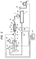
- Fig. 3 is a block diagram of a passage showing an embodiment of an ink supply system of the above device;
- Fig. 4 shows an embodiment of an ink bag used as the ink supply means;
- Fig. 5 shows an embodiment of an ink bag constituting a subtank;
- Fig. 6 shows an embodiment if the above subtank is housed in a case; and
- Figs. 7(a) to 7(c) respectively show another embodiment related to a form in which the ink bag constituting the above subtank is installed.
-
- Further details of the present invention will be described based upon preferred embodiments below.
- Fig. 1 shows an embodiment of the present invention. This embodiment includes a frame 2 including a window 1 with a width in which a recording medium as a printing object can pass. Ink-
jet recording heads 4 and 5 (see FIG. 2) reciprocated in the direction of the width of recording paper on acarriage 3 are provided over the window 1, apaper guide member 6 for supporting recording paper is provided under the window 1, a control panel 7 is provided at the end on the side at a position in which it is easy to operate and anink tank housing 9 with acover 8 which can be opened or closed is provided on a side opposite to the control panel 7. - Fig. 2 shows an embodiment of a printing mechanism of the above device. In this embodiment, the
carriage 3 mounts therecording head 4 for jetting black ink and therecording head 5 for jetting an ink droplet in yellow, cyan and magenta and is reciprocated by a carriage driving motor 11 via a timing belt 10 and ink is supplied to therecording heads - The ink supply system is composed of pressurizing
chambers ink tank housing 9,subtanks ink transport tubes 16 to 19 andink supply tubes subtanks 20 to 23 and therecording heads electromagnetic stop valves ink transport tubes 16 to 19. - A
capping device 32 for applying negative pressure to prevent blocking caused by the drying of ink in therecording heads 4 an 5 during non-printing, when ink is initially filled in therecording heads recording heads capping device 32 bysuction pump 33. - A supporting
plate 6a on the surface opposite to the recording paper in which thin holes are made is provided on thepaper guide 6 so as to apply negative pressure from thesuction port 34a of apump 34 to a recording paper and fix the recording paper on the supportingplate 6a by negative pressure. Theexhaust port 34b of thepump 34 is connected to the pressurizingchambers 12 to 15 respectively via theelectromagnetic stop valves - The ink bag as the ink supply means is respectively housed in the pressurizing
chambers 12 to 15 and is provided with a connecting port 41 (see FIG. 3) which can be connected to each of theink transport tubes 16 to 19 on oneshorter side 40a of theflexible bag 40 which is made, for example, of an aluminum laminated film. The aluminum laminated film may be made by putting aluminum foil as an intermediate layer between two films, for example an outside nylon film and an inside polyethylene film to function as a barrier to gas as shown in Fig. 4. Alternatively, theflexible bag 40 may also be made of a light transmissive film obtained by forming a silicon oxide layer by depositing silicon oxide on the surface a polymeric film having a light transmissive property in addition to good flexibility and sealing performance such as polyethylene terephthalate (PET) and a nylon and laminating a polymeric film such as polyethylene having excellent thermal weld characteristics on the surface. - In this embodiment, a
gusset 42 is provided on the longer side of theink bag 40 to increase the volume as much as possible and the centers of theshorter side 40b are welded to prevent thebag 40 from being over-expanded uselessly. - In this embodiment, an ink residual
quantity detecting plate 43 attached to the surface of theink bag 40, as shown in Fig. 3, is housed in the pressurizingchamber 12 and the connectingport 41 is connected to theink transport tube 16. The pressurizingchamber 12 is connected to atmosphere via theexhaust port 34b and thesuction port 34a of thepump 34 and thestop valve 39 so that the internal pressure can be arbitrarily adjusted. - In this configuration, the
ink bag 40 is pressurized by controlling the internal pressure of the pressurizingchamber 12, ink in theink bag 40 can be discharged into thesubtank 20 and the residual quantity of ink can be controlled by detecting the degree of the bulge of theink bag 40 as detected by the ink residualquantity detecting plate 43 and the inkresidual quantity detector 44. - A
bag 50 is made of an aluminum laminated film obtained by putting aluminum foil as an intermediate layer between two films, for example an outside nylon film and an inside polyethylene film to function as a barrier to gas as shown in Fig. 5, or a light transmissive film obtained by forming a silicon oxide layer by depositing silicon oxide on the surface a polymeric film having a light transmissive property in addition to good flexibility and sealing performance such as polyethylene terephthalate (PET) and a nylon. Abag 50 is formed of an aluminum laminated film by putting aluminum foil as an intermediate layer between two films, for example, an outside nylon film and an inside polyethylene film. The aluminum laminated film functions as a barrier to gas as shown in Fig. 5. Alternatively, thebag 50 may also be formed of a light transmissive film by forming a silicon oxide layer by depositing silicon oxide on the surface of a polymeric film such as polyethylene having a light transmissive property in addition to good flexibility and sealing performance such as polyethylene terephthalate (PET) and a nylon. Thebag 50 is formed in a size in which the shape can flexibly follow the quantity of ink, for example, with a capacity of approximately 100 to 300 cm3. Aninlet 51 connecting to theink transport tube 16 and anoutlet 52 connecting to theink supply tube 24 are provided on the opposite sides of thebag 50, thereby constituting thesubtank 20. Thus, thebag 50,inlet 51 and theink supply tube 24 constitute thesubtank 20. - In this embodiment, an ink
quantity detecting plate 53 is attached to the surface of theink bag 50 as shown in Fig. 6 and is housed in aprotective case 54. - By constructing the device as described above, the variation of pressure in the
subtank 20 caused by the inflow of ink from theink bag 40 and the consumption of ink in therecording head 4 is absorbed by expansion and contraction of theflexible bag 50. Accordingly, ink can be supplied to the recording head under a fixed pressure. The quantity of ink in thesubtank 20 can be controlled by detecting the displacement of an inkquantity detecting plate 53 which moves as a function of the degree of the bulge of theink bag 50 by an ink quantity detecting means 55. - That is, if it is detected by the ink quantity detecting means 55 that the quantity of ink in the subtank decreases to a first reference value or less, a
control unit 60 increases the internal pressure of the pressurizingchamber 12 by closing anelectromagnetic stop valve 39 and opening theelectromagnetic stop valve 35. This causes ink in the ink bag to be supplied to thesubtank 20 through the opening of theelectromagnetic stop valve 28. Thecontrol unit 60 receives a signal from the ink residual quantity detecting means 44 and the ink quantity detecting means 55 and outputs a driving signal to theelectromagnetic stop valves - When ink is filled up to a second reference value, the supply of ink from the
ink bag 40 to thesubtank 20 is stopped by closing theelectromagnetic stop valves electromagnetic stop valve 39. Therefore, the quantity of ink in thesubtank 20 is kept in a fixed range. - Particularly, in the case of the
subtank 20 which includes theink bag 50 which is made of a light transmissive film, as inside bubbles can be detected visually, bubbles can be securely removed. - In this embodiment, if ink is initially filled after purchase, first the
electromagnetic stop valve 28 and thepump 34 for forcing the recording paper against thepaper guide 6 are operated after theink bag 40 is set, theelectromagnetic stop valve 39 of the pressurizingchamber 12 housing theink bag 40 is closed, theelectromagnetic stop valve 35 is opened, hereby, pressure in the pressurizingchamber 12 is increased by air from theexhaust port 34b of thepump 34 and theink bag 40 is contracted. - The
recording head 4 is moved to thecapping device 32 in a non-printing area and thesuction pump 33 is operated with therecording head 4 sealed with thecapping device 32. Negative pressure in thecapping device 32 is applied to theink supply tube 24 and thesubtank 20 via therecording head 4, air and ink left in these members are discharged into thecapping device 32 and when suction is further continued, thesubtank 20 is squeezed by the atmospheric air and is discharged. - Next, when the
electromagnetic stop valve 28 is opened, ink in theink bag 40 flows into thesubtank 20 via theink transport tube 16 and when the ink reaches predetermined quantity, it flows into therecording head 4 via theink supply tube 24. It is desirable to open theelectromagnetic stop valve 35 if necessary with thesuction pump 33 operating, and to close theelectromagnetic stop valve 39 in order to pressurize theink bag 50. - As described above, as ink is filled in the
subtank 20 in a state in which theelectromagnetic stop valve 28 is closed and a passage including thesubtank 20 is under negative pressure, bubbles in thesubtank 20 can be securely removed without requiring a special bubble vent in thesubtank 20. - When printing is started after the filling of ink is finished as described above, the
recording head 4 jets an ink droplet on the surface of recording paper fixed by negative pressure by thepaper guide 6 corresponding to print data, thereby to execute printing and theink bag 50 supplies ink to therecording head 4 via theink supply tube 24, contracting as ink is consumed. - When the ink in the
subtank 20 is consumed by printing and the quantity of the ink has decreased down to the first reference value, a signal is outputted from the inkquantity detecting means 55. - The
control unit 60 initiates the supply of ink to thesubtank 20 by instructing to close theelectromagnetic stop valve 39 and to open theelectromagnetic valve 35 further to open theelectromagnetic stop valve 28, which pressurizes theink bag 40. In a process in which ink is supplied, ink flows into the subtank at some flow rate. However, as theink bag 50 disposed in thesubtank 20 absorbs the variation of pressure with its own flexibility, ink is supplied under fixed pressure to therecording head 4 without having the effect of the variation of pressure on therecording head 4. As a signal is outputted from the inkquantity detecting means 55 when ink is filled up to a second reference value of thesubtank 20 as described above, thecontrol unit 60 instructs the supply of ink to be stopped by instructing to close theelectromagnetic stop valve 28 to open theelectromagnetic stop valve 39 and to close theelectromagnetic stop valve 35. Printing is continued, keeping the quantity of ink in thesubtank 20 within a fixed range as described above. - In the meantime, if bubbles should come into the
subtank 20 while the ink-jet recording device is operated and the quality of printing is deteriorated, thesuction pump 33 is operated by closing theelectromagnetic stop valve 28 and sealing therecording head 4 with thecapping device 32. Hereby, bubbles which are stagnant in thesubtank 20, theink supply tube 24 and therecording head 4 can be discharged into thecapping device 32 without consuming ink in theink bag 40. - When the
electromagnetic stop valve 28 is opened after thesuction pump 33 has operated after a predetermined time has elapsed as described above, ink in theink bag 40 flows into thesubtank 20, further flows into therecording head 4 via theink supply tube 24 and printing is enabled. - If a signal is outputted from the ink residual
quantity detecting means 44 when printing is further continued, and when the ink in theink bag 40 is consumed and theink bag 40 becomes empty, thecontrol unit 60 prompts the user to supply ink via a warning means (not shown). While theink bag 40 is being replaced, printing can be continued by using ink stored in thesubtank 20, closing theelectromagnetic stop valve 28. Therefore, ink can be supplied without interrupting the printing operation. - At this time, even if a small quantity of bubbles enters into the
ink transport tube 16, they are caught in theink bag 50 due to the relatively large capacity of thebuffer tank 20, and are prevented from flowing into therecording head 4 and have, thus, no adverse effect on the printing operation. - In the above embodiment, the
ink bag 50 comprising thesubtank 20 is installed so that the flat surface is horizontal. However, as shown in Fig. 7(a), the ink bag may also be installed so that the flat surface is vertical. Also, when at least theink outlet 52 is arranged so that it lies below the first reference value as shown in Fig. 7(b), bubbles can be prevented from flowing into therecording head 4. When the ink bag is installed as shown in Fig. 7(c), anair vent 56 may be formed in the uppermost part. An electromagnetic stop valve is connected to thisair vent 56 and may also be open to atmospheric air when ink is filled. - In the above embodiment, the
subtank 20 is installed on the side of the printer, however, it is clear that if thesubtank 20 is installed on the carriage by connecting it via a flexible tube, similar action can be produced. - Also, in the above embodiment, the exhaust pressure of the
air pump 34 for attracting recording paper is utilized, however, an independent air pump for pressurizing may be also provided. A pressing plate of a size in which the whole flat surface of theink bag 50 is covered is provided. The ink bag may also be so constituted that the pressing plate is mechanically displaced. - Further, in the above embodiment, a case in which ink is supplied using the flexible ink bag is described. However, it is clear that even if the above ink bag is applied to an ink-jet recording head in which ink is supplied using a rigid cartridge such as a tank, similar action is produced.
- Further, in the above embodiment, the ink residual quantity detecting means such as the ink residual
quantity detecting plate 43 is provided to theink bag 40 to detect the residual quantity of ink. However, a shortage of ink in theink bag 40 can also be ascertained if the quantity of ink in thesubtank 20 does not exceed a reference value, even if theink bag 40 is pressurized for a predetermined time after the quantity of ink in thesubtank 20 has decreased down to the first reference value or less. - As described above, according to an aspect of the present invention, in the ink-jet recording device wherein the recording head for jetting an ink droplet corresponding to a printing signal is mounted on the carriage and ink is supplied from the ink reservoir to the recording head via the ink supply tube, as the subtank composed of the flexible ink bag provided with the ink inlet on one side and the ink outlet on the other side is connected on the way of the passage connecting the ink reservoir and the recording head, equal performance to a case in which ink is supplied to a recording head via a flexible ink bag with small capacity can be kept and the degree of the freedom of the body for supplying ink can be enhanced.
Claims (22)
- An ink-jet recording device in which a recording head (4) for jetting an ink droplet corresponding to a printing signal is mounted on a carriage (3) and ink is supplied from an ink reservoir (12) to said recording head (4) via an ink supply tube, wherein:a subtank (20) comprising a flexible ink bag (50) having an ink inlet (51) and an ink outlet (52) is connected to a passage connecting said ink reservoir (12) and said recording head (4).
- An ink-jet recording device according to claim 1, wherein a stop valve (28) is provided to a passage (16) connecting said subtank (20) and said ink reservoir (40).
- An ink-jet recording device according to claim 1 or 2, wherein said ink outlet (52) of said subtank (20) is arranged so that it is lower than a first predetermined reference level.
- An ink-jet recording device according to any of the preceding claims, wherein said ink bag (50) comprises a polymeric film having a layer functioning as a barrier to gas.
- An ink-jet recording device according to claim 4, wherein said layer functioning as a barrier to gas is made from a metal or silicon oxide.
- An ink-jet recording device according to any of the preceding claims, wherein said subtank (20) is provided with means (53, 55) for detecting the residual quantity of ink therein.
- An ink-jet recording device according to any of the preceding claims, wherein said subtank (20) is arranged on said carriage (3).
- An ink-jet recording device according to any of the preceding claims, wherein said subtank (20) is arranged so that its flat surface is horizontal.
- An ink-jet recording device according to any of claims 1 to 7, wherein said subtank (20) is arranged so that its flat surface is vertical.
- An ink-jet recording device according to any of the preceding claims, wherein said ink reservoir (12) comprises a flexible bag (40) and is pressurized by a pressurizing means.
- An ink-jet recording device according to claim 10, wherein said flexible bag (40) is pressurized by an air supply means (34).
- An ink-jet recording device according to claim 11, further comprising a paper guide (6) for supporting a recording medium, wherein negative pressure is applied to said paper guide (6) from a suction pump (34) and said air supply means (34) is said suction pump (34).
- An ink-jet recording device according to claim 10, wherein said pressurizing means comprises a plate for pressing said flexible bag (40) by mechanical displacement.
- An ink-jet recording device according to any of the preceding claims, wherein said subtank (20) is provided with an ink residual quantity detecting means (53, 55), and the residual quantity of ink in said subtank (20) is controlled based upon a signal from said ink residual quantity detecting means (53, 55).
- An ink filling method of an ink-jet recording device in which a recording head for jetting an ink droplet corresponding to a printing signal is mounted on a carriage, with a subtank comprising a flexible ink bag provided with an ink inlet and an ink outlet side connected to a passage connecting an ink reservoir and said recording head and a stop valve connected between said subtank and said ink reservoir, the method comprising the steps of:closing said stop valve, applying negative pressure to said recording head and pressing said subtank with atmospheric pressure; andopening said stop valve and filling ink into said subtank.
- An ink supply method of an ink-jet recording device in which a recording head for jetting an ink droplet corresponding to a printing signal is mounted on a carriage, with a subtank comprising a flexible ink bag provided with an ink inlet and an ink outlet connected to a passage connecting an ink reservoir and said recording head and a stop valve connected between said subtank and said ink reservoir, the method comprising the steps of:closing said stop valve and replacing said ink reservoir when the quantity of ink in said ink reservoir decreases below a predetermined level; andcontinuing to supply ink from said subtank to said recording head while said ink reservoir is being replaced.
- An ink-jet recording device comprising:an ink jet recording head (4) for jetting ink droplets onto a recording medium;an ink reservoir (12) for supplying ink to said ink jet recording head (4);a subtank (20) connected to said reservoir (12) and said ink jet recording head (4) for supplying ink to said ink jet recording head (4).
- The ink-jet recording device of claim 17, wherein the subtank (20) comprises a flexible ink bag (50) which supplies ink to said ink jet recording head (4) at a fixed pressure.
- The ink-jet recording device of claim 17 or 18, further comprising an ink detector (55) which detects the quantity of ink in said subtank (20).
- The ink-jet recording device of claim 19, wherein said detector (55) comprises a detecting plate (53) which measures the displacement of said ink bag (50).
- The ink-jet recording device of claim 19 or 20, further comprising a control unit (60) which causes ink to be supplied from said ink reservoir (12) to said subtank (20) when a level of ink in said subtank (20) decreases below a first predetermined value and which stops the supply of ink from said ink reservoir (12) to said subtank (20) when a level of ink in said subtank (20) exceeds a second predetermined value.
- The ink-jet recording device of any of claims 17 to 21, further comprising a valve (28) which closes a connection between said reservoir (12) and said ink jet recording head (4) when ink in said ink reservoir (12) is being replaced.
Applications Claiming Priority (2)
| Application Number | Priority Date | Filing Date | Title |
|---|---|---|---|
| JP1210198 | 1998-01-05 | ||
| JP10012101A JPH11192720A (en) | 1998-01-05 | 1998-01-05 | Ink jet recorder, ink filling method, and ink supplying method |
Publications (3)
| Publication Number | Publication Date |
|---|---|
| EP0927638A2 true EP0927638A2 (en) | 1999-07-07 |
| EP0927638A3 EP0927638A3 (en) | 1999-08-18 |
| EP0927638B1 EP0927638B1 (en) | 2001-07-18 |
Family
ID=11796187
Family Applications (1)
| Application Number | Title | Priority Date | Filing Date |
|---|---|---|---|
| EP98124704A Expired - Lifetime EP0927638B1 (en) | 1998-01-05 | 1998-12-24 | Ink-jet recording device with subtank between ink reservoir and recording head |
Country Status (4)
| Country | Link |
|---|---|
| US (1) | US6267474B1 (en) |
| EP (1) | EP0927638B1 (en) |
| JP (1) | JPH11192720A (en) |
| DE (1) | DE69801147T2 (en) |
Cited By (20)
| Publication number | Priority date | Publication date | Assignee | Title |
|---|---|---|---|---|
| EP1120258A2 (en) * | 2000-01-21 | 2001-08-01 | Seiko Epson Corporation | Ink cartridge, and ink-jet recording apparatus using the same |
| EP1120259A2 (en) * | 2000-01-21 | 2001-08-01 | Seiko Epson Corporation | Ink-jet recording apparatus |
| EP1188568A1 (en) * | 2000-03-27 | 2002-03-20 | Seiko Epson Corporation | Ink-jet recorder |
| EP1223039A1 (en) * | 2001-01-11 | 2002-07-17 | Hewlett-Packard Company | Printhead air management using unsaturated ink |
| EP1234673A2 (en) * | 2001-02-09 | 2002-08-28 | Seiko Epson Corporation | Ink jet recording apparatus, control and ink replenishing method executed in the same, ink supply system incorporated in the same, and method of managing ink amount supplied by the system |
| EP1270237A2 (en) * | 2001-06-18 | 2003-01-02 | Canon Kabushiki Kaisha | Inkjet printing apparatus and ink supplying method |
| EP1282522A1 (en) * | 2000-05-18 | 2003-02-12 | Mikoh Imaging Systems Pty Ltd | Print station |
| US6752491B2 (en) | 2001-02-23 | 2004-06-22 | Hewlett-Packard Development Company, L.P. | Inkjet printing system having extended heater resistor life |
| EP1454753A1 (en) * | 2003-03-05 | 2004-09-08 | Seiko Epson Corporation | Liquid container, liquid ejection device and liquid container case |
| NL1023215C2 (en) * | 2003-04-17 | 2004-10-19 | Stork Digital Imaging Bv | Pressure device, flexible supply holder and work holder, as well as supply system. |
| US6880910B2 (en) * | 2002-08-12 | 2005-04-19 | Sii Printek Inc. | Air damper, ink jet head, and ink jet recording apparatus |
| EP1603752A1 (en) * | 2003-03-18 | 2005-12-14 | Ricoh Company, Ltd. | Ink bag, ink cartridge and ink-et recording apparatus, ink filling method, ink refilling method, manufacturing method of ink cartridge, and recycling method of ink cartridge |
| WO2006065352A1 (en) * | 2004-12-15 | 2006-06-22 | Hewlett-Packard Development Company, L.P. | Fluid reservoir and ink pen assembly |
| EP1677984A2 (en) * | 2003-10-14 | 2006-07-12 | MacDermid Acumen, Inc. | Fluid delivery system for an ink jet print head |
| EP1710084A3 (en) * | 2000-06-16 | 2007-02-28 | Canon Kabushiki Kaisha | Solid semiconductor element, ink tank, ink jet recording apparatus provided with ink tank, and associated method of use |
| EP1864814A1 (en) * | 2005-03-30 | 2007-12-12 | Seiko Epson Corporation | Liquid container |
| EP1880856A1 (en) * | 2005-05-13 | 2008-01-23 | Brother Kogyo Kabushiki Kaisha | Ink jet recording apparatus |
| US7438400B2 (en) | 2003-07-16 | 2008-10-21 | Seiko Epson Corporation | Liquid container, liquid ejecting device, and method of checking arrangement of liquid storing packs |
| EP2274174A1 (en) * | 2008-05-14 | 2011-01-19 | Hewlett-Packard Development Company, L.P. | Printer ink delivery systems |
| CN101177069B (en) * | 2001-02-09 | 2012-06-13 | 精工爱普生株式会社 | Ink supply system and method of managing ink amount supplied by the system |
Families Citing this family (43)
| Publication number | Priority date | Publication date | Assignee | Title |
|---|---|---|---|---|
| DE60044020D1 (en) | 1999-11-05 | 2010-04-29 | Seiko Epson Corp | RECORDING DEVICE OF THE INK JET TYPE AND METHOD OF INK SUPPLYING THE UNDER TANK USING THE SAME DEVICE AND METHOD FOR CONTROLLING THE AMOUNT OF INK OF THE UNDER TANK BY MEANS OF THE SAME DEVICE |
| KR100583290B1 (en) | 2000-01-21 | 2006-05-25 | 세이코 엡슨 가부시키가이샤 | Ink cartridge for recording device |
| JP4510981B2 (en) * | 2000-02-29 | 2010-07-28 | セイコーエプソン株式会社 | Inkjet recording device |
| US6626516B2 (en) * | 2000-09-20 | 2003-09-30 | Canon Kabushiki Kaisha | Ink jet printing apparatus, method of supplying ink and method of recovering ink jet print head |
| JP4522620B2 (en) * | 2001-02-09 | 2010-08-11 | セイコーエプソン株式会社 | Ink supply system and ink supply amount management method in the system |
| JP4517519B2 (en) * | 2001-02-26 | 2010-08-04 | セイコーエプソン株式会社 | Ink pack support structure and ink supply apparatus provided with the same |
| JP3668439B2 (en) * | 2001-06-14 | 2005-07-06 | ソニーケミカル株式会社 | Adhesive film |
| WO2003053701A1 (en) * | 2001-12-21 | 2003-07-03 | Olympus Corporation | Ink jet printer |
| KR100387551B1 (en) * | 2002-03-12 | 2003-06-18 | Hanlim | Ink feeding device for large ink jet printer |
| US6877846B2 (en) * | 2002-05-03 | 2005-04-12 | Eastman Kodak Company | Replaceable ink jet supply with anti-siphon back pressure control |
| JP2004090432A (en) * | 2002-08-30 | 2004-03-25 | Seiko Epson Corp | Liquid injection device, tank for discharging liquid of liquid injection device, and liquid discharging method of liquid injection device |
| JP2005047058A (en) * | 2003-07-30 | 2005-02-24 | Canon Inc | Inkjet recording device |
| US7384133B2 (en) | 2003-08-08 | 2008-06-10 | Seiko Epson Corporation | Liquid container capable of maintaining airtightness |
| US7258432B2 (en) * | 2004-01-21 | 2007-08-21 | Silverbrook Research Pty Ltd | Inkjet printer cartridge with controlled refill |
| US7448734B2 (en) | 2004-01-21 | 2008-11-11 | Silverbrook Research Pty Ltd | Inkjet printer cartridge with pagewidth printhead |
| US20050157112A1 (en) | 2004-01-21 | 2005-07-21 | Silverbrook Research Pty Ltd | Inkjet printer cradle with shaped recess for receiving a printer cartridge |
| US20050206693A1 (en) * | 2004-03-22 | 2005-09-22 | Stephen Chen | High capacity ink supply apparatus |
| US7377626B2 (en) * | 2004-07-09 | 2008-05-27 | Nukote International, Inc. | External ink supply bag and method of filling the same |
| US20060007278A1 (en) * | 2004-07-09 | 2006-01-12 | Nu-Kote International, Inc., A Corporation Of Delaware | Ink delivery system for the continuous refill of ink jet cartridges |
| JP2006035484A (en) * | 2004-07-23 | 2006-02-09 | Seiko Epson Corp | Liquid container and method for detecting remaining quantity of liquid |
| JP2006137181A (en) * | 2004-10-15 | 2006-06-01 | Seiko Epson Corp | Filling method and liquid delivery device |
| JP4788142B2 (en) * | 2005-01-14 | 2011-10-05 | セイコーエプソン株式会社 | Liquid container and liquid ejecting apparatus |
| JP4725157B2 (en) * | 2005-03-28 | 2011-07-13 | セイコーエプソン株式会社 | Liquid ejector |
| US7530663B2 (en) * | 2005-10-11 | 2009-05-12 | Silverbrook Research Pty Ltd | Method of removing particulates from a printhead using a rotating roller |
| US7577384B2 (en) * | 2005-12-23 | 2009-08-18 | Xerox Corporation | Collapsible packaging system |
| US8967044B2 (en) * | 2006-02-21 | 2015-03-03 | R.R. Donnelley & Sons, Inc. | Apparatus for applying gating agents to a substrate and image generation kit |
| JP2007283557A (en) * | 2006-04-13 | 2007-11-01 | Seiko Epson Corp | Liquid container |
| JP2008037097A (en) | 2006-07-10 | 2008-02-21 | Seiko Epson Corp | Liquid-supplying system and liquid-consuming apparatus |
| JP2008143073A (en) | 2006-12-12 | 2008-06-26 | Ricoh Co Ltd | Image formation device and control method |
| JP5241515B2 (en) * | 2007-01-19 | 2013-07-17 | シャープ株式会社 | Ink ejection device |
| US8322835B2 (en) * | 2007-02-19 | 2012-12-04 | Seiko Epson Corporation | Sealing structure of fluid container, and method of manufacturing and reusing fluid container |
| JP2008230214A (en) * | 2007-02-19 | 2008-10-02 | Seiko Epson Corp | Sealing structure and sealing method of fluid lead-out part, fluid container, refilling fluid container, and its refilling method |
| CA2638279A1 (en) * | 2007-07-24 | 2009-01-24 | Richard H. Berg | Wide format ink cartridge |
| JP2009166358A (en) * | 2008-01-16 | 2009-07-30 | Seiko Epson Corp | Liquid supplying method, liquid supplying system, and liquid jet device |
| JP5561925B2 (en) * | 2008-10-14 | 2014-07-30 | 株式会社ミマキエンジニアリング | Bulk ink supply device |
| KR101215197B1 (en) * | 2012-03-21 | 2012-12-24 | 김영숙 | Ink-supplying apparatus and inkpack storage case |
| JP5692265B2 (en) * | 2013-03-07 | 2015-04-01 | セイコーエプソン株式会社 | Liquid ejecting apparatus, liquid supply apparatus, and liquid container |
| JP6384233B2 (en) * | 2014-09-24 | 2018-09-05 | ブラザー工業株式会社 | Printing device |
| US9573380B2 (en) * | 2015-03-23 | 2017-02-21 | Seiko Epson Corporation | Liquid discharging apparatus |
| JP6657583B2 (en) * | 2015-03-31 | 2020-03-04 | セイコーエプソン株式会社 | Liquid supply device and liquid consumption device |
| KR102346945B1 (en) * | 2015-08-11 | 2022-01-05 | 배준호 | The Unlimiting Refill Ink Supply Apparatus For Print Cartidge |
| JP7292947B2 (en) * | 2019-04-24 | 2023-06-19 | キヤノン株式会社 | INKJET RECORDING DEVICE AND CONTROL METHOD OF INKJET RECORDING DEVICE |
| US11198304B2 (en) * | 2019-04-26 | 2021-12-14 | Brother Kogyo Kabushiki Kaisha | Image-recording device having tank in communication with cartridge held by mount body |
Citations (6)
| Publication number | Priority date | Publication date | Assignee | Title |
|---|---|---|---|---|
| DE3244935A1 (en) * | 1982-12-04 | 1984-06-07 | Olympia Werke Ag, 2940 Wilhelmshaven | Ink printing mechanism for office machines |
| JPS6024954A (en) * | 1983-07-20 | 1985-02-07 | Canon Inc | Detection of residual ink amount in ink jet printer |
| JPS60179258A (en) * | 1984-02-28 | 1985-09-13 | Fujitsu Ltd | Ink feeding mechanism for ink jet printer |
| JPS62290544A (en) * | 1986-06-10 | 1987-12-17 | Nec Corp | Ink feed mechanism of ink jet printer |
| EP0714778A1 (en) * | 1994-05-17 | 1996-06-05 | Seiko Epson Corporation | Ink jet recorder and method of cleaning recording head |
| GB2304639A (en) * | 1995-09-05 | 1997-03-26 | Hewlett Packard Co | An ink delivery system for an ink-jet printer |
Family Cites Families (10)
| Publication number | Priority date | Publication date | Assignee | Title |
|---|---|---|---|---|
| JPS54151033A (en) * | 1978-05-18 | 1979-11-27 | Fujitsu Ltd | Ink feed device in ink jet recorder |
| US4207579A (en) * | 1979-01-08 | 1980-06-10 | The Mead Corporation | Reciprocating paper handling apparatus for use in an ink jet copier |
| JPS5616886U (en) * | 1979-07-17 | 1981-02-14 | ||
| DE3137970A1 (en) * | 1981-09-24 | 1983-03-31 | Olympia Werke Ag, 2940 Wilhelmshaven | INK WRITER FOR OFFICE MACHINES WITH INK WRITING HEAD AND INK RESERVOIR ARRANGED ON A MOVABLE CARRIAGE |
| US4432005A (en) * | 1982-05-10 | 1984-02-14 | Advanced Color Technology, Inc. | Ink control system for ink jet printer |
| US4604633A (en) * | 1982-12-08 | 1986-08-05 | Konishiroku Photo Industry Co., Ltd | Ink-jet recording apparatus |
| US4965596A (en) * | 1988-02-09 | 1990-10-23 | Canon Kabushiki Kaisha | Ink jet recording apparatus with waste ink distribution paths to plural cartridges |
| JP2822586B2 (en) | 1990-04-19 | 1998-11-11 | 富士ゼロックス株式会社 | inkjet printer |
| US5831655A (en) * | 1995-03-23 | 1998-11-03 | Seiko Epson Corporation | Ink jet recording apparatus |
| JP3414605B2 (en) | 1995-12-25 | 2003-06-09 | セイコーエプソン株式会社 | Ink jet recording apparatus and maintenance method |
-
1998
- 1998-01-05 JP JP10012101A patent/JPH11192720A/en active Pending
- 1998-12-24 EP EP98124704A patent/EP0927638B1/en not_active Expired - Lifetime
- 1998-12-24 DE DE69801147T patent/DE69801147T2/en not_active Expired - Lifetime
-
1999
- 1999-01-05 US US09/225,359 patent/US6267474B1/en not_active Expired - Lifetime
Patent Citations (6)
| Publication number | Priority date | Publication date | Assignee | Title |
|---|---|---|---|---|
| DE3244935A1 (en) * | 1982-12-04 | 1984-06-07 | Olympia Werke Ag, 2940 Wilhelmshaven | Ink printing mechanism for office machines |
| JPS6024954A (en) * | 1983-07-20 | 1985-02-07 | Canon Inc | Detection of residual ink amount in ink jet printer |
| JPS60179258A (en) * | 1984-02-28 | 1985-09-13 | Fujitsu Ltd | Ink feeding mechanism for ink jet printer |
| JPS62290544A (en) * | 1986-06-10 | 1987-12-17 | Nec Corp | Ink feed mechanism of ink jet printer |
| EP0714778A1 (en) * | 1994-05-17 | 1996-06-05 | Seiko Epson Corporation | Ink jet recorder and method of cleaning recording head |
| GB2304639A (en) * | 1995-09-05 | 1997-03-26 | Hewlett Packard Co | An ink delivery system for an ink-jet printer |
Non-Patent Citations (3)
| Title |
|---|
| PATENT ABSTRACTS OF JAPAN vol. 009, no. 146 (M-389), 21 June 1985 & JP 60 024954 A (CANON KK), 7 February 1985 * |
| PATENT ABSTRACTS OF JAPAN vol. 010, no. 021 (M-449), 28 January 1986 & JP 60 179258 A (FUJITSU KK), 13 September 1985 * |
| PATENT ABSTRACTS OF JAPAN vol. 012, no. 179 (M-701), 26 May 1988 & JP 62 290544 A (NEC CORP), 17 December 1987 * |
Cited By (65)
| Publication number | Priority date | Publication date | Assignee | Title |
|---|---|---|---|---|
| US6874873B2 (en) | 1998-03-09 | 2005-04-05 | Hewlett-Packard Development Company, L.P. | Printhead air management using unsaturated ink |
| US6547377B2 (en) | 1998-03-09 | 2003-04-15 | Hewlett-Packard Company | Printhead air management using unsaturated ink |
| US7784923B2 (en) | 1999-10-08 | 2010-08-31 | Seiko Epson Corporation | Ink cartridge, and ink-jet recording apparatus using the same |
| EP1916114A1 (en) | 2000-01-21 | 2008-04-30 | Seiko Epson Corporation | Ink cartridge, and ink-jet recording apparatus using the same |
| EP1120259A2 (en) * | 2000-01-21 | 2001-08-01 | Seiko Epson Corporation | Ink-jet recording apparatus |
| EP1693213A2 (en) * | 2000-01-21 | 2006-08-23 | Seiko Epson Corporation | Ink cartridge, and ink-jet recording apparatus using the same |
| US8998394B2 (en) | 2000-01-21 | 2015-04-07 | Seiko Epson Corporation | Ink cartridge, and ink-jet recording apparatus using the same |
| US8636347B2 (en) | 2000-01-21 | 2014-01-28 | Seiko Epson Corporation | Ink cartridge, and ink-jet recording apparatus using the same |
| US7048363B2 (en) | 2000-01-21 | 2006-05-23 | Seiko Epson Corporation | Ink-jet recording apparatus |
| US6913350B2 (en) | 2000-01-21 | 2005-07-05 | Seiko Epson Corporation | Ink-jet recording apparatus |
| EP1120259A3 (en) * | 2000-01-21 | 2001-12-12 | Seiko Epson Corporation | Ink-jet recording apparatus |
| US7152965B2 (en) | 2000-01-21 | 2006-12-26 | Seiko Epson Corporation | Ink cartridge, and ink-jet recording apparatus using the same |
| EP1120258A3 (en) * | 2000-01-21 | 2001-11-28 | Seiko Epson Corporation | Ink cartridge, and ink-jet recording apparatus using the same |
| US6582068B2 (en) | 2000-01-21 | 2003-06-24 | Seiko Epson Corporation | Ink cartridge, and ink-jet recording apparatus using the same |
| EP1120258A2 (en) * | 2000-01-21 | 2001-08-01 | Seiko Epson Corporation | Ink cartridge, and ink-jet recording apparatus using the same |
| US6733114B2 (en) | 2000-01-21 | 2004-05-11 | Seiko Epson Corporation | Ink-jet recording apparatus |
| EP1693213A3 (en) * | 2000-01-21 | 2007-02-14 | Seiko Epson Corporation | Ink cartridge, and ink-jet recording apparatus using the same |
| US6758556B2 (en) | 2000-01-21 | 2004-07-06 | Seiko Epson Corporation | Ink cartridge, and ink-jet recording apparatus using the same |
| EP1849608A1 (en) * | 2000-01-21 | 2007-10-31 | Seiko Epson Corporation | Ink cartridge, and ink-jet recording apparatus using the same |
| US7316462B2 (en) | 2000-03-27 | 2008-01-08 | Seiko Epson Corporation | Ink jet recording apparatus |
| EP1188568A1 (en) * | 2000-03-27 | 2002-03-20 | Seiko Epson Corporation | Ink-jet recorder |
| EP1188568A4 (en) * | 2000-03-27 | 2002-12-18 | Seiko Epson Corp | Ink-jet recorder |
| AU2001258052B8 (en) * | 2000-05-18 | 2007-01-18 | Mikoh Imaging Systems Pty Ltd | Print station |
| EP1282522A1 (en) * | 2000-05-18 | 2003-02-12 | Mikoh Imaging Systems Pty Ltd | Print station |
| EP1282522A4 (en) * | 2000-05-18 | 2005-05-18 | Mikoh Imaging Systems Pty Ltd | Print station |
| AU2001258052B2 (en) * | 2000-05-18 | 2006-08-24 | Mikoh Imaging Systems Pty Ltd | Print station |
| US7210755B2 (en) | 2000-06-16 | 2007-05-01 | Canon Kabushiki Kaisha | Solid semiconductor element, ink tank, ink jet recording apparatus provided with ink tank, liquid information acquiring method and liquid physical property change discriminating method |
| EP1710084A3 (en) * | 2000-06-16 | 2007-02-28 | Canon Kabushiki Kaisha | Solid semiconductor element, ink tank, ink jet recording apparatus provided with ink tank, and associated method of use |
| US7922274B2 (en) | 2000-06-16 | 2011-04-12 | Canon Kabushiki Kaisha | Solid semiconductor element, ink tank, ink jet recording apparatus provided with ink tank, liquid information acquiring method and liquid physical property change discriminating method |
| EP1223039A1 (en) * | 2001-01-11 | 2002-07-17 | Hewlett-Packard Company | Printhead air management using unsaturated ink |
| US7077513B2 (en) | 2001-02-09 | 2006-07-18 | Seiko Epson Corporation | Ink jet recording apparatus, control and ink replenishing method executed in the same, ink supply system incorporated in the same, and method of managing ink amount supplied by the system |
| US6840604B2 (en) | 2001-02-09 | 2005-01-11 | Seiko Epson Corporation | Ink jet recording apparatus, control and ink replenishing method executed in the same, ink supply system incorporated in the same, and method of managing ink amount supplied by the system |
| CN100360316C (en) * | 2001-02-09 | 2008-01-09 | 精工爱普生株式会社 | Ink jet recording apparatus and method for operating same |
| EP1234673A2 (en) * | 2001-02-09 | 2002-08-28 | Seiko Epson Corporation | Ink jet recording apparatus, control and ink replenishing method executed in the same, ink supply system incorporated in the same, and method of managing ink amount supplied by the system |
| EP1234673A3 (en) * | 2001-02-09 | 2002-11-06 | Seiko Epson Corporation | Ink jet recording apparatus, control and ink replenishing method executed in the same, ink supply system incorporated in the same, and method of managing ink amount supplied by the system |
| US6883905B2 (en) | 2001-02-09 | 2005-04-26 | Seiko Epson Corporation | Ink jet recording apparatus, control and ink replenishing method executed in the same, ink supply system incorporated in the same, and method of managing ink amount supplied by the system |
| CN1292907C (en) * | 2001-02-09 | 2007-01-03 | 精工爱普生株式会社 | Ink jetting recorder and its operation method |
| CN101177069B (en) * | 2001-02-09 | 2012-06-13 | 精工爱普生株式会社 | Ink supply system and method of managing ink amount supplied by the system |
| US6752491B2 (en) | 2001-02-23 | 2004-06-22 | Hewlett-Packard Development Company, L.P. | Inkjet printing system having extended heater resistor life |
| EP1270237A2 (en) * | 2001-06-18 | 2003-01-02 | Canon Kabushiki Kaisha | Inkjet printing apparatus and ink supplying method |
| EP1270237A3 (en) * | 2001-06-18 | 2003-01-08 | Canon Kabushiki Kaisha | Inkjet printing apparatus and ink supplying method |
| US6663233B2 (en) | 2001-06-18 | 2003-12-16 | Canon Kabushiki Kaisha | Inkjet printing apparatus and ink supplying method |
| US6880910B2 (en) * | 2002-08-12 | 2005-04-19 | Sii Printek Inc. | Air damper, ink jet head, and ink jet recording apparatus |
| KR101091326B1 (en) * | 2003-03-05 | 2011-12-07 | 세이코 엡슨 가부시키가이샤 | Liquid container, liquid ejection device and liquid container case |
| EP1454753A1 (en) * | 2003-03-05 | 2004-09-08 | Seiko Epson Corporation | Liquid container, liquid ejection device and liquid container case |
| US7488067B2 (en) | 2003-03-05 | 2009-02-10 | Seiko Epson Corporation | Liquid container, liquid ejection device and liquid container case |
| US7097294B2 (en) | 2003-03-05 | 2006-08-29 | Seiko Epson Corporation | Liquid container, liquid ejection device and liquid container case |
| EP1685965A1 (en) * | 2003-03-05 | 2006-08-02 | Seiko Epson Corporation | Liquid container, liquid ejection device and liquid container case |
| AU2004200945B2 (en) * | 2003-03-05 | 2009-10-29 | Seiko Epson Corporation | Liquid Container, Liquid Ejection Device and Liquid Container Case |
| EP1603752A4 (en) * | 2003-03-18 | 2008-04-02 | Ricoh Kk | Ink bag, ink cartridge and ink-jet recording apparatus, ink filling method, ink refilling method, manufacturing method of ink cartridge, and recycling method of ink cartridge |
| EP1603752A1 (en) * | 2003-03-18 | 2005-12-14 | Ricoh Company, Ltd. | Ink bag, ink cartridge and ink-et recording apparatus, ink filling method, ink refilling method, manufacturing method of ink cartridge, and recycling method of ink cartridge |
| US7798619B2 (en) | 2003-04-17 | 2010-09-21 | Stork Digital Imaging B.V. | Printing device, flexible reservoir and working container and feed system |
| NL1023215C2 (en) * | 2003-04-17 | 2004-10-19 | Stork Digital Imaging Bv | Pressure device, flexible supply holder and work holder, as well as supply system. |
| WO2004091921A1 (en) | 2003-04-17 | 2004-10-28 | Stork Digital Imaging B.V. | Printing device, flexible reservoir and working container and feed system |
| US7438400B2 (en) | 2003-07-16 | 2008-10-21 | Seiko Epson Corporation | Liquid container, liquid ejecting device, and method of checking arrangement of liquid storing packs |
| EP1677984A4 (en) * | 2003-10-14 | 2009-10-21 | Hewlett Packard Development Co | Fluid delivery system for an ink jet print head |
| EP1677984A2 (en) * | 2003-10-14 | 2006-07-12 | MacDermid Acumen, Inc. | Fluid delivery system for an ink jet print head |
| WO2006065352A1 (en) * | 2004-12-15 | 2006-06-22 | Hewlett-Packard Development Company, L.P. | Fluid reservoir and ink pen assembly |
| EP1864814A4 (en) * | 2005-03-30 | 2010-06-02 | Seiko Epson Corp | Liquid container |
| EP1864814A1 (en) * | 2005-03-30 | 2007-12-12 | Seiko Epson Corporation | Liquid container |
| EP1880856A1 (en) * | 2005-05-13 | 2008-01-23 | Brother Kogyo Kabushiki Kaisha | Ink jet recording apparatus |
| EP1880856A4 (en) * | 2005-05-13 | 2011-03-02 | Brother Ind Ltd | Ink jet recording apparatus |
| EP2274174A1 (en) * | 2008-05-14 | 2011-01-19 | Hewlett-Packard Development Company, L.P. | Printer ink delivery systems |
| US8424986B2 (en) | 2008-05-14 | 2013-04-23 | Hewlett-Packard Development Company, L.P. | Printer ink delivery system with intermediate buffer ink tanks |
| EP2274174A4 (en) * | 2008-05-14 | 2011-05-11 | Hewlett Packard Development Co | Printer ink delivery systems |
Also Published As
| Publication number | Publication date |
|---|---|
| EP0927638A3 (en) | 1999-08-18 |
| DE69801147T2 (en) | 2002-03-21 |
| EP0927638B1 (en) | 2001-07-18 |
| JPH11192720A (en) | 1999-07-21 |
| US6267474B1 (en) | 2001-07-31 |
| DE69801147D1 (en) | 2001-08-23 |
Similar Documents
| Publication | Publication Date | Title |
|---|---|---|
| EP0927638B1 (en) | Ink-jet recording device with subtank between ink reservoir and recording head | |
| EP0894631B1 (en) | Ink-jet recording apparatus | |
| US7077513B2 (en) | Ink jet recording apparatus, control and ink replenishing method executed in the same, ink supply system incorporated in the same, and method of managing ink amount supplied by the system | |
| JP3419220B2 (en) | Ink jet recording device | |
| JP5224754B2 (en) | Inkjet recording device | |
| JP2003246077A (en) | Liquid storage vessel, inkjet cartridge and inkjet recorder | |
| WO2006070518A1 (en) | Tube pump, ink jet recording device, and ink feeding method | |
| JP2001301192A (en) | Ink jet recorder | |
| KR20020096961A (en) | Inkjet printing apparatus and ink supplying method | |
| JP3508815B2 (en) | Ink jet recording device | |
| JP2003159811A (en) | Inkjet recorder | |
| JPH11320901A (en) | Ink-jet recording apparatus | |
| JPH1148493A (en) | Ink jet recorder | |
| JP4089231B2 (en) | Ink filling method and ink jet recording apparatus | |
| JP3512057B2 (en) | Ink jet recording device | |
| JP3363760B2 (en) | Ink supply device and printing device | |
| JP2009023251A (en) | Inkjet recording apparatus | |
| JP4602116B2 (en) | Ink jet recording apparatus, tube pump, and liquid feeding method | |
| JP2000301732A (en) | Ink jet recording apparatus | |
| JP4009821B2 (en) | Ink filling method and ink jet recording apparatus | |
| JP4687111B2 (en) | Inkjet recording device | |
| US20200290363A1 (en) | Liquid ejection apparatus and liquid filling method in liquid ejection apparatus | |
| JP2002264358A (en) | Ink jet imaging apparatus | |
| JP2934016B2 (en) | Ink jet recording device | |
| JPH03234664A (en) | Ink jet recording device |
Legal Events
| Date | Code | Title | Description |
|---|---|---|---|
| PUAI | Public reference made under article 153(3) epc to a published international application that has entered the european phase |
Free format text: ORIGINAL CODE: 0009012 |
|
| PUAL | Search report despatched |
Free format text: ORIGINAL CODE: 0009013 |
|
| AK | Designated contracting states |
Kind code of ref document: A2 Designated state(s): DE FR GB |
|
| AX | Request for extension of the european patent |
Free format text: AL;LT;LV;MK;RO;SI |
|
| AK | Designated contracting states |
Kind code of ref document: A3 Designated state(s): AT BE CH CY DE DK ES FI FR GB GR IE IT LI LU MC NL PT SE |
|
| AX | Request for extension of the european patent |
Free format text: AL;LT;LV;MK;RO;SI |
|
| 17P | Request for examination filed |
Effective date: 20000215 |
|
| AKX | Designation fees paid |
Free format text: DE FR GB |
|
| 17Q | First examination report despatched |
Effective date: 20000407 |
|
| GRAG | Despatch of communication of intention to grant |
Free format text: ORIGINAL CODE: EPIDOS AGRA |
|
| GRAG | Despatch of communication of intention to grant |
Free format text: ORIGINAL CODE: EPIDOS AGRA |
|
| GRAH | Despatch of communication of intention to grant a patent |
Free format text: ORIGINAL CODE: EPIDOS IGRA |
|
| GRAH | Despatch of communication of intention to grant a patent |
Free format text: ORIGINAL CODE: EPIDOS IGRA |
|
| GRAA | (expected) grant |
Free format text: ORIGINAL CODE: 0009210 |
|
| AK | Designated contracting states |
Kind code of ref document: B1 Designated state(s): DE FR GB |
|
| REF | Corresponds to: |
Ref document number: 69801147 Country of ref document: DE Date of ref document: 20010823 |
|
| ET | Fr: translation filed | ||
| REG | Reference to a national code |
Ref country code: GB Ref legal event code: IF02 |
|
| PLBE | No opposition filed within time limit |
Free format text: ORIGINAL CODE: 0009261 |
|
| STAA | Information on the status of an ep patent application or granted ep patent |
Free format text: STATUS: NO OPPOSITION FILED WITHIN TIME LIMIT |
|
| 26N | No opposition filed | ||
| REG | Reference to a national code |
Ref country code: FR Ref legal event code: PLFP Year of fee payment: 18 |
|
| REG | Reference to a national code |
Ref country code: FR Ref legal event code: PLFP Year of fee payment: 19 |
|
| REG | Reference to a national code |
Ref country code: FR Ref legal event code: PLFP Year of fee payment: 20 |
|
| PGFP | Annual fee paid to national office [announced via postgrant information from national office to epo] |
Ref country code: FR Payment date: 20171113 Year of fee payment: 20 |
|
| PGFP | Annual fee paid to national office [announced via postgrant information from national office to epo] |
Ref country code: GB Payment date: 20171220 Year of fee payment: 20 |
|
| PGFP | Annual fee paid to national office [announced via postgrant information from national office to epo] |
Ref country code: DE Payment date: 20171220 Year of fee payment: 20 |
|
| REG | Reference to a national code |
Ref country code: DE Ref legal event code: R071 Ref document number: 69801147 Country of ref document: DE |
|
| REG | Reference to a national code |
Ref country code: GB Ref legal event code: PE20 Expiry date: 20181223 |
|
| PG25 | Lapsed in a contracting state [announced via postgrant information from national office to epo] |
Ref country code: GB Free format text: LAPSE BECAUSE OF EXPIRATION OF PROTECTION Effective date: 20181223 |