EP0925494B1 - A micro flow system for particle separation and analysis - Google Patents
A micro flow system for particle separation and analysis Download PDFInfo
- Publication number
- EP0925494B1 EP0925494B1 EP97938810A EP97938810A EP0925494B1 EP 0925494 B1 EP0925494 B1 EP 0925494B1 EP 97938810 A EP97938810 A EP 97938810A EP 97938810 A EP97938810 A EP 97938810A EP 0925494 B1 EP0925494 B1 EP 0925494B1
- Authority
- EP
- European Patent Office
- Prior art keywords
- flow channel
- particles
- flow
- micro
- field
- Prior art date
- Legal status (The legal status is an assumption and is not a legal conclusion. Google has not performed a legal analysis and makes no representation as to the accuracy of the status listed.)
- Expired - Lifetime
Links
- 239000002245 particle Substances 0.000 title claims abstract description 250
- 238000000926 separation method Methods 0.000 title description 98
- 238000004458 analytical method Methods 0.000 title description 18
- 239000012530 fluid Substances 0.000 claims abstract description 79
- 238000007599 discharging Methods 0.000 claims abstract description 10
- 239000003153 chemical reaction reagent Substances 0.000 claims abstract description 8
- 210000004027 cell Anatomy 0.000 claims description 107
- 230000005291 magnetic effect Effects 0.000 claims description 63
- 239000000872 buffer Substances 0.000 claims description 50
- 238000000034 method Methods 0.000 claims description 36
- 230000001605 fetal effect Effects 0.000 claims description 20
- 230000008774 maternal effect Effects 0.000 claims description 18
- 238000001514 detection method Methods 0.000 claims description 17
- 239000006249 magnetic particle Substances 0.000 claims description 15
- 239000011324 bead Substances 0.000 claims description 14
- 230000003287 optical effect Effects 0.000 claims description 14
- 206010028980 Neoplasm Diseases 0.000 claims description 13
- 201000011510 cancer Diseases 0.000 claims description 13
- 238000010186 staining Methods 0.000 claims description 12
- 238000012544 monitoring process Methods 0.000 claims description 11
- 238000002203 pretreatment Methods 0.000 claims description 8
- 238000011534 incubation Methods 0.000 claims description 5
- 238000005259 measurement Methods 0.000 claims description 5
- 210000003463 organelle Anatomy 0.000 claims description 4
- 108090000623 proteins and genes Proteins 0.000 claims description 3
- 102000004169 proteins and genes Human genes 0.000 claims description 3
- 210000000349 chromosome Anatomy 0.000 claims description 2
- 229910000859 α-Fe Inorganic materials 0.000 claims description 2
- 239000004005 microsphere Substances 0.000 claims 1
- 238000003556 assay Methods 0.000 abstract description 2
- 239000000523 sample Substances 0.000 description 72
- XUIMIQQOPSSXEZ-UHFFFAOYSA-N Silicon Chemical compound [Si] XUIMIQQOPSSXEZ-UHFFFAOYSA-N 0.000 description 19
- 229910052710 silicon Inorganic materials 0.000 description 17
- 239000010703 silicon Substances 0.000 description 17
- 230000008901 benefit Effects 0.000 description 16
- VYPSYNLAJGMNEJ-UHFFFAOYSA-N Silicium dioxide Chemical compound O=[Si]=O VYPSYNLAJGMNEJ-UHFFFAOYSA-N 0.000 description 13
- 210000004369 blood Anatomy 0.000 description 12
- 239000008280 blood Substances 0.000 description 12
- 238000000684 flow cytometry Methods 0.000 description 10
- 230000005684 electric field Effects 0.000 description 9
- 239000011521 glass Substances 0.000 description 9
- 238000007885 magnetic separation Methods 0.000 description 9
- 230000001965 increasing effect Effects 0.000 description 7
- 239000007788 liquid Substances 0.000 description 7
- 239000002699 waste material Substances 0.000 description 7
- 102000053602 DNA Human genes 0.000 description 6
- 108020004414 DNA Proteins 0.000 description 6
- 238000012360 testing method Methods 0.000 description 6
- 229910052681 coesite Inorganic materials 0.000 description 5
- 229910052906 cristobalite Inorganic materials 0.000 description 5
- 238000002474 experimental method Methods 0.000 description 5
- 238000002955 isolation Methods 0.000 description 5
- 229910052761 rare earth metal Inorganic materials 0.000 description 5
- 150000002910 rare earth metals Chemical class 0.000 description 5
- 239000000377 silicon dioxide Substances 0.000 description 5
- 229910052682 stishovite Inorganic materials 0.000 description 5
- 229910052905 tridymite Inorganic materials 0.000 description 5
- 101000738771 Homo sapiens Receptor-type tyrosine-protein phosphatase C Proteins 0.000 description 4
- 102100037422 Receptor-type tyrosine-protein phosphatase C Human genes 0.000 description 4
- 210000000601 blood cell Anatomy 0.000 description 4
- 238000010586 diagram Methods 0.000 description 4
- 238000009792 diffusion process Methods 0.000 description 4
- 238000002826 magnetic-activated cell sorting Methods 0.000 description 4
- 238000004519 manufacturing process Methods 0.000 description 4
- 239000011325 microbead Substances 0.000 description 4
- 238000002360 preparation method Methods 0.000 description 4
- 239000004593 Epoxy Substances 0.000 description 3
- 101000835093 Homo sapiens Transferrin receptor protein 1 Proteins 0.000 description 3
- 239000004809 Teflon Substances 0.000 description 3
- 229920006362 Teflon® Polymers 0.000 description 3
- 102100026144 Transferrin receptor protein 1 Human genes 0.000 description 3
- 238000011161 development Methods 0.000 description 3
- 238000006073 displacement reaction Methods 0.000 description 3
- 238000005516 engineering process Methods 0.000 description 3
- 238000005530 etching Methods 0.000 description 3
- 239000005350 fused silica glass Substances 0.000 description 3
- 230000005484 gravity Effects 0.000 description 3
- 239000003550 marker Substances 0.000 description 3
- 239000000463 material Substances 0.000 description 3
- 238000002156 mixing Methods 0.000 description 3
- 239000000203 mixture Substances 0.000 description 3
- -1 organic cells Substances 0.000 description 3
- 230000005298 paramagnetic effect Effects 0.000 description 3
- 230000008569 process Effects 0.000 description 3
- YBJHBAHKTGYVGT-ZKWXMUAHSA-N (+)-Biotin Chemical compound N1C(=O)N[C@@H]2[C@H](CCCCC(=O)O)SC[C@@H]21 YBJHBAHKTGYVGT-ZKWXMUAHSA-N 0.000 description 2
- XKRFYHLGVUSROY-UHFFFAOYSA-N Argon Chemical compound [Ar] XKRFYHLGVUSROY-UHFFFAOYSA-N 0.000 description 2
- UMFRIFDUVVWICJ-UHFFFAOYSA-N [Ge].[Sm] Chemical compound [Ge].[Sm] UMFRIFDUVVWICJ-UHFFFAOYSA-N 0.000 description 2
- 239000012472 biological sample Substances 0.000 description 2
- 230000006037 cell lysis Effects 0.000 description 2
- 230000001413 cellular effect Effects 0.000 description 2
- 238000003745 diagnosis Methods 0.000 description 2
- 238000002405 diagnostic procedure Methods 0.000 description 2
- 238000010790 dilution Methods 0.000 description 2
- 239000012895 dilution Substances 0.000 description 2
- 230000000694 effects Effects 0.000 description 2
- 238000011156 evaluation Methods 0.000 description 2
- JEIPFZHSYJVQDO-UHFFFAOYSA-N ferric oxide Chemical compound O=[Fe]O[Fe]=O JEIPFZHSYJVQDO-UHFFFAOYSA-N 0.000 description 2
- 229960005191 ferric oxide Drugs 0.000 description 2
- 230000005294 ferromagnetic effect Effects 0.000 description 2
- 210000004700 fetal blood Anatomy 0.000 description 2
- 238000001943 fluorescence-activated cell sorting Methods 0.000 description 2
- PCHJSUWPFVWCPO-UHFFFAOYSA-N gold Chemical compound [Au] PCHJSUWPFVWCPO-UHFFFAOYSA-N 0.000 description 2
- 239000010931 gold Substances 0.000 description 2
- 229910052737 gold Inorganic materials 0.000 description 2
- UQSXHKLRYXJYBZ-UHFFFAOYSA-N iron oxide Inorganic materials [Fe]=O UQSXHKLRYXJYBZ-UHFFFAOYSA-N 0.000 description 2
- 235000013980 iron oxide Nutrition 0.000 description 2
- 229910052751 metal Inorganic materials 0.000 description 2
- 239000002184 metal Substances 0.000 description 2
- 238000000386 microscopy Methods 0.000 description 2
- 244000052769 pathogen Species 0.000 description 2
- 238000000206 photolithography Methods 0.000 description 2
- 229920002120 photoresistant polymer Polymers 0.000 description 2
- 238000001020 plasma etching Methods 0.000 description 2
- 239000004033 plastic Substances 0.000 description 2
- 229920003023 plastic Polymers 0.000 description 2
- 229920000642 polymer Polymers 0.000 description 2
- 239000000843 powder Substances 0.000 description 2
- 238000012545 processing Methods 0.000 description 2
- 239000012264 purified product Substances 0.000 description 2
- 239000004065 semiconductor Substances 0.000 description 2
- 229920002379 silicone rubber Polymers 0.000 description 2
- 239000000126 substance Substances 0.000 description 2
- 238000005406 washing Methods 0.000 description 2
- XLYOFNOQVPJJNP-UHFFFAOYSA-N water Substances O XLYOFNOQVPJJNP-UHFFFAOYSA-N 0.000 description 2
- RBTBFTRPCNLSDE-UHFFFAOYSA-N 3,7-bis(dimethylamino)phenothiazin-5-ium Chemical compound C1=CC(N(C)C)=CC2=[S+]C3=CC(N(C)C)=CC=C3N=C21 RBTBFTRPCNLSDE-UHFFFAOYSA-N 0.000 description 1
- DJHGAFSJWGLOIV-UHFFFAOYSA-K Arsenate3- Chemical compound [O-][As]([O-])([O-])=O DJHGAFSJWGLOIV-UHFFFAOYSA-K 0.000 description 1
- ZOXJGFHDIHLPTG-UHFFFAOYSA-N Boron Chemical compound [B] ZOXJGFHDIHLPTG-UHFFFAOYSA-N 0.000 description 1
- RYGMFSIKBFXOCR-UHFFFAOYSA-N Copper Chemical compound [Cu] RYGMFSIKBFXOCR-UHFFFAOYSA-N 0.000 description 1
- GYHNNYVSQQEPJS-UHFFFAOYSA-N Gallium Chemical compound [Ga] GYHNNYVSQQEPJS-UHFFFAOYSA-N 0.000 description 1
- HTTJABKRGRZYRN-UHFFFAOYSA-N Heparin Chemical compound OC1C(NC(=O)C)C(O)OC(COS(O)(=O)=O)C1OC1C(OS(O)(=O)=O)C(O)C(OC2C(C(OS(O)(=O)=O)C(OC3C(C(O)C(O)C(O3)C(O)=O)OS(O)(=O)=O)C(CO)O2)NS(O)(=O)=O)C(C(O)=O)O1 HTTJABKRGRZYRN-UHFFFAOYSA-N 0.000 description 1
- 241000531743 Pelargonium trifidum Species 0.000 description 1
- 229920005372 Plexiglas® Polymers 0.000 description 1
- 208000007660 Residual Neoplasm Diseases 0.000 description 1
- 229910000831 Steel Inorganic materials 0.000 description 1
- 108010090804 Streptavidin Proteins 0.000 description 1
- 210000001744 T-lymphocyte Anatomy 0.000 description 1
- DPKHZNPWBDQZCN-UHFFFAOYSA-N acridine orange free base Chemical compound C1=CC(N(C)C)=CC2=NC3=CC(N(C)C)=CC=C3C=C21 DPKHZNPWBDQZCN-UHFFFAOYSA-N 0.000 description 1
- 238000002669 amniocentesis Methods 0.000 description 1
- 239000012491 analyte Substances 0.000 description 1
- 239000003146 anticoagulant agent Substances 0.000 description 1
- 229940127219 anticoagulant drug Drugs 0.000 description 1
- 238000013459 approach Methods 0.000 description 1
- 229910052786 argon Inorganic materials 0.000 description 1
- 238000003491 array Methods 0.000 description 1
- 229940000489 arsenate Drugs 0.000 description 1
- 230000001580 bacterial effect Effects 0.000 description 1
- 238000010256 biochemical assay Methods 0.000 description 1
- 239000012620 biological material Substances 0.000 description 1
- 229960002685 biotin Drugs 0.000 description 1
- 235000020958 biotin Nutrition 0.000 description 1
- 239000011616 biotin Substances 0.000 description 1
- 229910052796 boron Inorganic materials 0.000 description 1
- 239000000969 carrier Substances 0.000 description 1
- 230000006727 cell loss Effects 0.000 description 1
- 210000000170 cell membrane Anatomy 0.000 description 1
- 239000002458 cell surface marker Substances 0.000 description 1
- 239000006285 cell suspension Substances 0.000 description 1
- 239000000919 ceramic Substances 0.000 description 1
- 238000012512 characterization method Methods 0.000 description 1
- 238000006243 chemical reaction Methods 0.000 description 1
- 210000004252 chorionic villi Anatomy 0.000 description 1
- KPLQYGBQNPPQGA-UHFFFAOYSA-N cobalt samarium Chemical compound [Co].[Sm] KPLQYGBQNPPQGA-UHFFFAOYSA-N 0.000 description 1
- 229910052802 copper Inorganic materials 0.000 description 1
- 239000010949 copper Substances 0.000 description 1
- 230000008878 coupling Effects 0.000 description 1
- 238000010168 coupling process Methods 0.000 description 1
- 238000005859 coupling reaction Methods 0.000 description 1
- 238000004163 cytometry Methods 0.000 description 1
- 230000001419 dependent effect Effects 0.000 description 1
- 201000010099 disease Diseases 0.000 description 1
- 208000037265 diseases, disorders, signs and symptoms Diseases 0.000 description 1
- 239000003814 drug Substances 0.000 description 1
- 230000005686 electrostatic field Effects 0.000 description 1
- 210000003743 erythrocyte Anatomy 0.000 description 1
- 230000005284 excitation Effects 0.000 description 1
- 238000004401 flow injection analysis Methods 0.000 description 1
- GNBHRKFJIUUOQI-UHFFFAOYSA-N fluorescein Chemical compound O1C(=O)C2=CC=CC=C2C21C1=CC=C(O)C=C1OC1=CC(O)=CC=C21 GNBHRKFJIUUOQI-UHFFFAOYSA-N 0.000 description 1
- 239000007850 fluorescent dye Substances 0.000 description 1
- 239000000446 fuel Substances 0.000 description 1
- 229910052733 gallium Inorganic materials 0.000 description 1
- 238000010448 genetic screening Methods 0.000 description 1
- 238000011331 genomic analysis Methods 0.000 description 1
- 229910052732 germanium Inorganic materials 0.000 description 1
- GNPVGFCGXDBREM-UHFFFAOYSA-N germanium atom Chemical compound [Ge] GNPVGFCGXDBREM-UHFFFAOYSA-N 0.000 description 1
- 230000036541 health Effects 0.000 description 1
- 229960002897 heparin Drugs 0.000 description 1
- 229920000669 heparin Polymers 0.000 description 1
- 239000008241 heterogeneous mixture Substances 0.000 description 1
- 238000009396 hybridization Methods 0.000 description 1
- 230000001900 immune effect Effects 0.000 description 1
- 230000001939 inductive effect Effects 0.000 description 1
- 230000036512 infertility Effects 0.000 description 1
- 238000001802 infusion Methods 0.000 description 1
- 238000002347 injection Methods 0.000 description 1
- 239000007924 injection Substances 0.000 description 1
- 230000002452 interceptive effect Effects 0.000 description 1
- 238000011835 investigation Methods 0.000 description 1
- 238000002372 labelling Methods 0.000 description 1
- 210000000265 leukocyte Anatomy 0.000 description 1
- 238000011068 loading method Methods 0.000 description 1
- 229920002521 macromolecule Polymers 0.000 description 1
- 239000006247 magnetic powder Substances 0.000 description 1
- 238000000838 magnetophoresis Methods 0.000 description 1
- 238000012423 maintenance Methods 0.000 description 1
- 150000002739 metals Chemical class 0.000 description 1
- 229960000907 methylthioninium chloride Drugs 0.000 description 1
- 239000011859 microparticle Substances 0.000 description 1
- 238000003801 milling Methods 0.000 description 1
- 238000011527 multiparameter analysis Methods 0.000 description 1
- 102000039446 nucleic acids Human genes 0.000 description 1
- 108020004707 nucleic acids Proteins 0.000 description 1
- 150000007523 nucleic acids Chemical class 0.000 description 1
- 230000001717 pathogenic effect Effects 0.000 description 1
- 230000000704 physical effect Effects 0.000 description 1
- 239000004926 polymethyl methacrylate Substances 0.000 description 1
- 238000001556 precipitation Methods 0.000 description 1
- 238000003793 prenatal diagnosis Methods 0.000 description 1
- 238000009609 prenatal screening Methods 0.000 description 1
- 238000011084 recovery Methods 0.000 description 1
- 230000009467 reduction Effects 0.000 description 1
- 229910000938 samarium–cobalt magnet Inorganic materials 0.000 description 1
- 238000005070 sampling Methods 0.000 description 1
- 238000004062 sedimentation Methods 0.000 description 1
- 238000010187 selection method Methods 0.000 description 1
- 230000035945 sensitivity Effects 0.000 description 1
- 238000002444 silanisation Methods 0.000 description 1
- 239000007787 solid Substances 0.000 description 1
- 239000012798 spherical particle Substances 0.000 description 1
- 229910001220 stainless steel Inorganic materials 0.000 description 1
- 239000010935 stainless steel Substances 0.000 description 1
- 239000010959 steel Substances 0.000 description 1
- 239000008174 sterile solution Substances 0.000 description 1
- 238000003860 storage Methods 0.000 description 1
- 239000000725 suspension Substances 0.000 description 1
- 230000001225 therapeutic effect Effects 0.000 description 1
- 238000002560 therapeutic procedure Methods 0.000 description 1
- 230000001052 transient effect Effects 0.000 description 1
- 230000003612 virological effect Effects 0.000 description 1
- 238000012800 visualization Methods 0.000 description 1
- 238000003631 wet chemical etching Methods 0.000 description 1
- 210000002268 wool Anatomy 0.000 description 1
Images


Classifications
-
- B—PERFORMING OPERATIONS; TRANSPORTING
- B03—SEPARATION OF SOLID MATERIALS USING LIQUIDS OR USING PNEUMATIC TABLES OR JIGS; MAGNETIC OR ELECTROSTATIC SEPARATION OF SOLID MATERIALS FROM SOLID MATERIALS OR FLUIDS; SEPARATION BY HIGH-VOLTAGE ELECTRIC FIELDS
- B03C—MAGNETIC OR ELECTROSTATIC SEPARATION OF SOLID MATERIALS FROM SOLID MATERIALS OR FLUIDS; SEPARATION BY HIGH-VOLTAGE ELECTRIC FIELDS
- B03C5/00—Separating dispersed particles from liquids by electrostatic effect
- B03C5/02—Separators
- B03C5/022—Non-uniform field separators
- B03C5/028—Non-uniform field separators using travelling electric fields, i.e. travelling wave dielectrophoresis [TWD]
-
- B—PERFORMING OPERATIONS; TRANSPORTING
- B01—PHYSICAL OR CHEMICAL PROCESSES OR APPARATUS IN GENERAL
- B01D—SEPARATION
- B01D57/00—Separation, other than separation of solids, not fully covered by a single other group or subclass, e.g. B03C
- B01D57/02—Separation, other than separation of solids, not fully covered by a single other group or subclass, e.g. B03C by electrophoresis
-
- B—PERFORMING OPERATIONS; TRANSPORTING
- B01—PHYSICAL OR CHEMICAL PROCESSES OR APPARATUS IN GENERAL
- B01J—CHEMICAL OR PHYSICAL PROCESSES, e.g. CATALYSIS OR COLLOID CHEMISTRY; THEIR RELEVANT APPARATUS
- B01J19/00—Chemical, physical or physico-chemical processes in general; Their relevant apparatus
- B01J19/0093—Microreactors, e.g. miniaturised or microfabricated reactors
-
- B—PERFORMING OPERATIONS; TRANSPORTING
- B01—PHYSICAL OR CHEMICAL PROCESSES OR APPARATUS IN GENERAL
- B01L—CHEMICAL OR PHYSICAL LABORATORY APPARATUS FOR GENERAL USE
- B01L3/00—Containers or dishes for laboratory use, e.g. laboratory glassware; Droppers
- B01L3/50—Containers for the purpose of retaining a material to be analysed, e.g. test tubes
- B01L3/502—Containers for the purpose of retaining a material to be analysed, e.g. test tubes with fluid transport, e.g. in multi-compartment structures
- B01L3/5027—Containers for the purpose of retaining a material to be analysed, e.g. test tubes with fluid transport, e.g. in multi-compartment structures by integrated microfluidic structures, i.e. dimensions of channels and chambers are such that surface tension forces are important, e.g. lab-on-a-chip
- B01L3/502761—Containers for the purpose of retaining a material to be analysed, e.g. test tubes with fluid transport, e.g. in multi-compartment structures by integrated microfluidic structures, i.e. dimensions of channels and chambers are such that surface tension forces are important, e.g. lab-on-a-chip specially adapted for handling suspended solids or molecules independently from the bulk fluid flow, e.g. for trapping or sorting beads, for physically stretching molecules
-
- B—PERFORMING OPERATIONS; TRANSPORTING
- B01—PHYSICAL OR CHEMICAL PROCESSES OR APPARATUS IN GENERAL
- B01L—CHEMICAL OR PHYSICAL LABORATORY APPARATUS FOR GENERAL USE
- B01L3/00—Containers or dishes for laboratory use, e.g. laboratory glassware; Droppers
- B01L3/50—Containers for the purpose of retaining a material to be analysed, e.g. test tubes
- B01L3/502—Containers for the purpose of retaining a material to be analysed, e.g. test tubes with fluid transport, e.g. in multi-compartment structures
- B01L3/5027—Containers for the purpose of retaining a material to be analysed, e.g. test tubes with fluid transport, e.g. in multi-compartment structures by integrated microfluidic structures, i.e. dimensions of channels and chambers are such that surface tension forces are important, e.g. lab-on-a-chip
- B01L3/502769—Containers for the purpose of retaining a material to be analysed, e.g. test tubes with fluid transport, e.g. in multi-compartment structures by integrated microfluidic structures, i.e. dimensions of channels and chambers are such that surface tension forces are important, e.g. lab-on-a-chip characterised by multiphase flow arrangements
- B01L3/502776—Containers for the purpose of retaining a material to be analysed, e.g. test tubes with fluid transport, e.g. in multi-compartment structures by integrated microfluidic structures, i.e. dimensions of channels and chambers are such that surface tension forces are important, e.g. lab-on-a-chip characterised by multiphase flow arrangements specially adapted for focusing or laminating flows
-
- B—PERFORMING OPERATIONS; TRANSPORTING
- B03—SEPARATION OF SOLID MATERIALS USING LIQUIDS OR USING PNEUMATIC TABLES OR JIGS; MAGNETIC OR ELECTROSTATIC SEPARATION OF SOLID MATERIALS FROM SOLID MATERIALS OR FLUIDS; SEPARATION BY HIGH-VOLTAGE ELECTRIC FIELDS
- B03C—MAGNETIC OR ELECTROSTATIC SEPARATION OF SOLID MATERIALS FROM SOLID MATERIALS OR FLUIDS; SEPARATION BY HIGH-VOLTAGE ELECTRIC FIELDS
- B03C1/00—Magnetic separation
- B03C1/02—Magnetic separation acting directly on the substance being separated
- B03C1/035—Open gradient magnetic separators, i.e. separators in which the gap is unobstructed, characterised by the configuration of the gap
-
- B—PERFORMING OPERATIONS; TRANSPORTING
- B03—SEPARATION OF SOLID MATERIALS USING LIQUIDS OR USING PNEUMATIC TABLES OR JIGS; MAGNETIC OR ELECTROSTATIC SEPARATION OF SOLID MATERIALS FROM SOLID MATERIALS OR FLUIDS; SEPARATION BY HIGH-VOLTAGE ELECTRIC FIELDS
- B03C—MAGNETIC OR ELECTROSTATIC SEPARATION OF SOLID MATERIALS FROM SOLID MATERIALS OR FLUIDS; SEPARATION BY HIGH-VOLTAGE ELECTRIC FIELDS
- B03C5/00—Separating dispersed particles from liquids by electrostatic effect
- B03C5/02—Separators
- B03C5/022—Non-uniform field separators
- B03C5/026—Non-uniform field separators using open-gradient differential dielectric separation, i.e. using electrodes of special shapes for non-uniform field creation, e.g. Fluid Integrated Circuit [FIC]
-
- G—PHYSICS
- G01—MEASURING; TESTING
- G01N—INVESTIGATING OR ANALYSING MATERIALS BY DETERMINING THEIR CHEMICAL OR PHYSICAL PROPERTIES
- G01N33/00—Investigating or analysing materials by specific methods not covered by groups G01N1/00 - G01N31/00
- G01N33/48—Biological material, e.g. blood, urine; Haemocytometers
- G01N33/50—Chemical analysis of biological material, e.g. blood, urine; Testing involving biospecific ligand binding methods; Immunological testing
- G01N33/53—Immunoassay; Biospecific binding assay; Materials therefor
- G01N33/569—Immunoassay; Biospecific binding assay; Materials therefor for microorganisms, e.g. protozoa, bacteria, viruses
- G01N33/56966—Animal cells
-
- B—PERFORMING OPERATIONS; TRANSPORTING
- B01—PHYSICAL OR CHEMICAL PROCESSES OR APPARATUS IN GENERAL
- B01L—CHEMICAL OR PHYSICAL LABORATORY APPARATUS FOR GENERAL USE
- B01L2200/00—Solutions for specific problems relating to chemical or physical laboratory apparatus
- B01L2200/06—Fluid handling related problems
- B01L2200/0636—Focussing flows, e.g. to laminate flows
-
- B—PERFORMING OPERATIONS; TRANSPORTING
- B01—PHYSICAL OR CHEMICAL PROCESSES OR APPARATUS IN GENERAL
- B01L—CHEMICAL OR PHYSICAL LABORATORY APPARATUS FOR GENERAL USE
- B01L2200/00—Solutions for specific problems relating to chemical or physical laboratory apparatus
- B01L2200/06—Fluid handling related problems
- B01L2200/0647—Handling flowable solids, e.g. microscopic beads, cells, particles
- B01L2200/0652—Sorting or classification of particles or molecules
-
- B—PERFORMING OPERATIONS; TRANSPORTING
- B01—PHYSICAL OR CHEMICAL PROCESSES OR APPARATUS IN GENERAL
- B01L—CHEMICAL OR PHYSICAL LABORATORY APPARATUS FOR GENERAL USE
- B01L2300/00—Additional constructional details
- B01L2300/06—Auxiliary integrated devices, integrated components
- B01L2300/0627—Sensor or part of a sensor is integrated
- B01L2300/0636—Integrated biosensor, microarrays
-
- B—PERFORMING OPERATIONS; TRANSPORTING
- B01—PHYSICAL OR CHEMICAL PROCESSES OR APPARATUS IN GENERAL
- B01L—CHEMICAL OR PHYSICAL LABORATORY APPARATUS FOR GENERAL USE
- B01L2300/00—Additional constructional details
- B01L2300/06—Auxiliary integrated devices, integrated components
- B01L2300/0627—Sensor or part of a sensor is integrated
- B01L2300/0645—Electrodes
-
- B—PERFORMING OPERATIONS; TRANSPORTING
- B01—PHYSICAL OR CHEMICAL PROCESSES OR APPARATUS IN GENERAL
- B01L—CHEMICAL OR PHYSICAL LABORATORY APPARATUS FOR GENERAL USE
- B01L2300/00—Additional constructional details
- B01L2300/08—Geometry, shape and general structure
- B01L2300/0809—Geometry, shape and general structure rectangular shaped
- B01L2300/0816—Cards, e.g. flat sample carriers usually with flow in two horizontal directions
-
- B—PERFORMING OPERATIONS; TRANSPORTING
- B01—PHYSICAL OR CHEMICAL PROCESSES OR APPARATUS IN GENERAL
- B01L—CHEMICAL OR PHYSICAL LABORATORY APPARATUS FOR GENERAL USE
- B01L2300/00—Additional constructional details
- B01L2300/08—Geometry, shape and general structure
- B01L2300/0861—Configuration of multiple channels and/or chambers in a single devices
- B01L2300/0864—Configuration of multiple channels and/or chambers in a single devices comprising only one inlet and multiple receiving wells, e.g. for separation, splitting
-
- B—PERFORMING OPERATIONS; TRANSPORTING
- B01—PHYSICAL OR CHEMICAL PROCESSES OR APPARATUS IN GENERAL
- B01L—CHEMICAL OR PHYSICAL LABORATORY APPARATUS FOR GENERAL USE
- B01L2300/00—Additional constructional details
- B01L2300/08—Geometry, shape and general structure
- B01L2300/0861—Configuration of multiple channels and/or chambers in a single devices
- B01L2300/0867—Multiple inlets and one sample wells, e.g. mixing, dilution
-
- B—PERFORMING OPERATIONS; TRANSPORTING
- B01—PHYSICAL OR CHEMICAL PROCESSES OR APPARATUS IN GENERAL
- B01L—CHEMICAL OR PHYSICAL LABORATORY APPARATUS FOR GENERAL USE
- B01L2400/00—Moving or stopping fluids
- B01L2400/04—Moving fluids with specific forces or mechanical means
- B01L2400/0403—Moving fluids with specific forces or mechanical means specific forces
- B01L2400/0415—Moving fluids with specific forces or mechanical means specific forces electrical forces, e.g. electrokinetic
- B01L2400/0421—Moving fluids with specific forces or mechanical means specific forces electrical forces, e.g. electrokinetic electrophoretic flow
-
- B—PERFORMING OPERATIONS; TRANSPORTING
- B01—PHYSICAL OR CHEMICAL PROCESSES OR APPARATUS IN GENERAL
- B01L—CHEMICAL OR PHYSICAL LABORATORY APPARATUS FOR GENERAL USE
- B01L2400/00—Moving or stopping fluids
- B01L2400/04—Moving fluids with specific forces or mechanical means
- B01L2400/0403—Moving fluids with specific forces or mechanical means specific forces
- B01L2400/0415—Moving fluids with specific forces or mechanical means specific forces electrical forces, e.g. electrokinetic
- B01L2400/0424—Dielectrophoretic forces
-
- B—PERFORMING OPERATIONS; TRANSPORTING
- B01—PHYSICAL OR CHEMICAL PROCESSES OR APPARATUS IN GENERAL
- B01L—CHEMICAL OR PHYSICAL LABORATORY APPARATUS FOR GENERAL USE
- B01L2400/00—Moving or stopping fluids
- B01L2400/04—Moving fluids with specific forces or mechanical means
- B01L2400/0403—Moving fluids with specific forces or mechanical means specific forces
- B01L2400/043—Moving fluids with specific forces or mechanical means specific forces magnetic forces
-
- B—PERFORMING OPERATIONS; TRANSPORTING
- B01—PHYSICAL OR CHEMICAL PROCESSES OR APPARATUS IN GENERAL
- B01L—CHEMICAL OR PHYSICAL LABORATORY APPARATUS FOR GENERAL USE
- B01L2400/00—Moving or stopping fluids
- B01L2400/04—Moving fluids with specific forces or mechanical means
- B01L2400/0475—Moving fluids with specific forces or mechanical means specific mechanical means and fluid pressure
- B01L2400/0487—Moving fluids with specific forces or mechanical means specific mechanical means and fluid pressure fluid pressure, pneumatics
-
- B—PERFORMING OPERATIONS; TRANSPORTING
- B01—PHYSICAL OR CHEMICAL PROCESSES OR APPARATUS IN GENERAL
- B01L—CHEMICAL OR PHYSICAL LABORATORY APPARATUS FOR GENERAL USE
- B01L2400/00—Moving or stopping fluids
- B01L2400/08—Regulating or influencing the flow resistance
- B01L2400/084—Passive control of flow resistance
-
- G01N15/1023—
-
- G—PHYSICS
- G01—MEASURING; TESTING
- G01N—INVESTIGATING OR ANALYSING MATERIALS BY DETERMINING THEIR CHEMICAL OR PHYSICAL PROPERTIES
- G01N15/00—Investigating characteristics of particles; Investigating permeability, pore-volume, or surface-area of porous materials
- G01N15/10—Investigating individual particles
- G01N15/1031—Investigating individual particles by measuring electrical or magnetic effects thereof, e.g. conductivity or capacity
-
- G—PHYSICS
- G01—MEASURING; TESTING
- G01N—INVESTIGATING OR ANALYSING MATERIALS BY DETERMINING THEIR CHEMICAL OR PHYSICAL PROPERTIES
- G01N15/00—Investigating characteristics of particles; Investigating permeability, pore-volume, or surface-area of porous materials
- G01N15/10—Investigating individual particles
- G01N15/14—Electro-optical investigation, e.g. flow cytometers
- G01N15/1484—Electro-optical investigation, e.g. flow cytometers microstructural devices
-
- G01N15/149—
-
- G—PHYSICS
- G01—MEASURING; TESTING
- G01N—INVESTIGATING OR ANALYSING MATERIALS BY DETERMINING THEIR CHEMICAL OR PHYSICAL PROPERTIES
- G01N15/00—Investigating characteristics of particles; Investigating permeability, pore-volume, or surface-area of porous materials
- G01N15/10—Investigating individual particles
- G01N2015/1006—Investigating individual particles for cytology
-
- G01N2015/1028—
Definitions
- the present invention relates to methods and apparatuses for detection, separation, sorting, and analysis of particles, such as cells, cell organelles, beads, molecules, such as Deoxyribonucleic acid (DNA), proteins, etc. in a fluid.
- the invention relates to particle separation by using different forces such as magnetic, electrophoretic, hydrodynamic and/or gravitational forces, e.g. for utilisation in flow cytometry, light microscopy, electrophoretic separation, magnetophoresis, etc.
- Flow cytometry is a well known technique that is used for high throughput measurements of optical and/or electrical characteristics of microscopic biological samples. Flow cytometry instruments analyse and isolate cells and organelles with particular physical, biochemical, and immunological properties.
- cell sorting by flow cytometry has been the method of choice for isolation of specific cell populations by surface markers.
- flow cytometry fluorescence activated cell sorting
- cell sorting by flow cytometry suffers from several drawbacks, especially high dilution of desired cell sample, low speed and sterility problems.
- the equipment is very costly with high operation and maintenance cost, making the technique available only to a limited number of laboratories.
- Immunomagnetic cell separation e.g. as commercially introduced by Dynal A/S and Miltenyi Biotec, has become an established method for cell analysis in clinical diagnostics Due to the relatively low prize, this method is attractive in flow cytometry, especially in sorting of rare cellular events. For example, sorting of fetal cells contained in maternal blood sample provides a non-invasive alternative to prenatal diagnostic procedures, such as amniocentesis of chorionic villus sampling. Another rare event scenario is the detection of low conçentration of cancer cells which has an important role in diagnosis of minimal residual disease and evaluation of appropriate therapies. Another medical application for cell sorting systems is the diagnosis of bacterial and viral diseases.
- the present invention relates to development of a low cost non-invasive diagnostic test method and devices for carrying out such tests that include measuring, monitoring, sorting and analysing samples containing particles, such as organic cells, microbeads, cell organells and macromolecules such as DNA.
- the present invention provides a cheap, fast and reliable method and devices for handling, sorting and analysis of such particles.
- Separation may be performed according to various physical properties, such as fluorescent properties or other optical properties, magnetic properties, density, electrical properties, etc.
- particle separation is performed by aligning the particles in one row of particles in a micro flow channel so that particles can be treated individually.
- It is a still further objective of the invention is develop a system for separation and analysis of fetal cells in whole maternal blood samples using an integrated automated micro flow system.
- the system is designed by downscaling and combining different methods for handling, manipulation and analysis of biochemical samples.
- prenatal diagnostics by analysis of fetal cells separated from a whole maternal blood sample is an area, which can benefit from advances in miniaturisation.
- It is another objective of the invention is develop a system for separation and analysis of cancer cells from a sample containing cancer cells and healthy cells using an integrated automated micro flow system.
- the system is also designed by downscaling and combining different methods for handling, manipulation and analysis of biochemical samples.
- cancer diagnostics by analysis of cancer cells separated from healthy cells is also an area which can benefit from advances in miniaturisation.
- a micro flow system for separating particles comprising a member having
- a method of separating fetal cells from maternal cells comprising the steps of selective magnetically staining of fetal cells in a fluid containing fetal and maternal cells, guiding a flow of the fluid containing the fetal cells through a flow channel in such a way that one fetal cell at the time passes a cross-section of the flow channel, positioning the flow channel in a magnetic field that is substantially perpendicular to a longitudinal axis of the flow channel so that magnetically stained fetal cells residing in the flow channel are deflected in the direction of the magnetic field.
- a method for separating cancer cells from other cells comprising the steps of selective magnetically staining of cancer cells in a fluid containing cancer and other cells, guiding a flow of the fluid containing the cancer cells through a flow channel in such a way that one cancer cell at the time passes a cross-section of the flow channel, positioning the flow channel in a magnetic field that is substantially perpendicular to a longitudinal axis of the flow channel so that magnetically stained cancer cells residing in the flow channel are deflected in the direction of the magnetic field.
- the particles to be separated from other particles in a fluid and/or to be separated from the fluid containing the particles may comprise living cells, chromosomes, organelles, beads, biomolecules, such as Deoxyribonucleic acid (DNA), proteins, etc.
- the flow through the flow channel is a laminar flow so that flow of particles are predictable and easy to control, e.g. with a flow of guiding buffers.
- the stream of particles can be positioned as desired within the flow channel, e.g. by controlling flow velocities of the fluid containing particles at the particle inlet of the member and flow velocities of guiding buffers at corresponding inlets.
- the flow channel is small for the flow through the channel to have a low Reynolds number, e.g., in the range of 0.01-500, such as 0.05-50, preferably 0.1-25.
- a low Reynolds number e.g., in the range of 0.01-500, such as 0.05-50, preferably 0.1-25.
- the illustrated flow channels of the micro flow system have a width ranging from 0,1 to 0.65 mm, preferably ranging from 0.1 to 0.4 mm, in particular ranging from 0.1 to 0.2 mm, and a depth ranging from 0.04 to 0.2 mm, preferably ranging from 0.04 to 0.1.
- this area is in the range of 0.004 to 0.11 mm 2 , in particular in the range of 0.004 to 0.02 mm 2 .
- the system is operating with total volumetric flow rates of 0.1 up to 200 ⁇ l/min, which gives a flow velocity of 15 mm/min up to 180 mm/min.
- the average residence time of a particle inside the flow channel which corresponds to a separation time ranging from 0.1 to 6 sec.
- the residence time of the sample is defined by the total volumetric flow rate of the system.
- the micro flow system may comprise flow rate adjustment means for adjustment of the time the particles reside in the flow channel.
- the fluid channel is sized so that for efficient separation, particles are displaced 10 - 30 ⁇ m in the flow channel.
- the particle may only be exposed to a field for a very short period of time and thus, continuous separation of particles may be facilitated.
- the micro flow system may further comprise second outlet means for discharging particles having been deflected in the flow channel.
- the micro flow system comprises second inlet means for entering a first guiding buffer into the flow channel together with the fluid containing particles.
- the two fluids flow through the flow channel in parallel abutting each other along a small area extending along a longitudinal axis of the flow channel whereby the cross-section and the path through the flow channel of the flow of the fluid containing particles may be controlled by the first guiding buffer flow.
- particles in the fluid containing particles may be deflected into the guiding buffer fluid when the two fluids pass the field essentially perpendicular to the longitudinal axis of the flow channel.
- two (or even more) outlets may be provided at the down stream end of the flow channel for discharging the guiding buffer now containing separated particles and fluid substantially without particles susceptible to the field essentially perpendicular the flow channel, correspondingly.
- the micro flow system may further comprise third inlet means for entering a second guiding buffer for improved control of the path of particle flow through the flow channel.
- third inlet means for entering a second guiding buffer for improved control of the path of particle flow through the flow channel.
- the cross-sectional area of the domain containing the sample it is possible to control the cross-sectional area of the domain containing the sample to be a little larger than the cross-sectional area of the particles by adjusting the volumetric flow rates of the sample and of the one or two guiding buffers in such a way that the particles contained in the sample are aligned in a single row of particles.
- This is a very important feature since it enables individual treatment of each particle and it leads to a sensitive method of sorting particles according to their susceptibility to a field.
- a sample flow layer thickness less than 1 ⁇ m may be achieved.
- the channel depth is small enough, e.g. below 50 ⁇ m, to allow observation of the particles flowing through the channel by a microscope.
- the micro flow system comprises a cover, e.g. a transparent or translucent cover, for covering the flow channel.
- a cover e.g. a transparent or translucent cover, for covering the flow channel.
- the cover is transparent or translucent, it will be possible to observe events in the flow channel, e.g. passage of a stained or coloured particle or cell.
- the member with the flow channel may be produced from any suitable material, such as silicon, polymers, such as Plexiglas, Teflon, etc., glass, ceramics, metals, such as copper, alumna, stainless steel, etc., etc.
- the channel may be provided in the member by any suitable manufacturing process, such as milling, etching, etc.
- the member is a silicon chip manufactured utilising photolithography and the channel is etched into the silicon chip.
- the field may be a magnetic field, an electric field, a gravity field, etc., and any combination of such fields.
- a magnetic field may be generated by permanent magnets, such as rare earth magnets, such as samarium-germanium magnets, a mixture of ferromagnetic powder and epoxy, etc., etc., electromagnets, e.g., in silicon integrated electromagnets, etc.
- the magnets are preferably positioned adjacent to the flow channel so that the magnetic field is substantially perpendicular to a longitudinal axis of the flow channel.
- the magnets are positioned in and glued to rectangular slots that are etched into a silicon chip.
- the slots are located adjacent to the separation flow channel.
- a permanent magnet or an electromagnet can be received by slots in the micro flow system.
- the slots are, e.g., 0.5 mm wide, 0.5 mm long and 0.2 mm deep.
- a solid magnetic block, i.e. rare earth magnet can be glued into the slot.
- a mixture of ferromagnetic powder and epoxy can be injected into the slots to produce a high magnetic field gradient.
- the strength of the magnetic field inside the micro flow system may be adjustable. If an electromagnet is used for generation of the magnetic field, the magnitude of the field may be varied by varying the amplitude of the voltage input to the electromagnet. If a permanent magnet generated the magnetic field, the magnitude of the field may be varied by varying the distance between the magnet and the flow channel of the micro flow system.
- the net displacement of a particle in the micro flow system depends on the force applied to it by the field. This can be utilised for separation of a first group of particles of various types in a fluid into a plurality of set of particles; each set comprising a specific type of particles.
- a micro flow system with e.g. five separation outlets may be used to separate a fluid containing particles into five sets of particles, each set comprising particles that are influenced by the field with a force of a specific magnitude, in the following denoted particles with a specific F-value.
- Particles with a low F-valuc are only deflected by a small amount by the field and are discharged from the flow channel through a corresponding outlet port. Particle deflection is increased with increasing F-values whereby such particles are discharged from the flow channel through the corresponding other outlets.
- the particles to be separated from other particles in a fluid and/or to be separated from the fluid containing the particles may be magnetically stained to facilitate separation in a magnetic field.
- staining is to be understood in a broad sense.
- the term is intended to cover any way of marking a particle thereby facilitating detection of the particle.
- a cell may be stained with a fluorescent substance, such as acridin orange, methylene blue, etc, facilitating detection of the stained particles by a fluorescence detector, or, a particle is said to be magnetically stained when it is coupled to a magnetic microbead.
- the microbead may for example carry a monoclonal or polyclonal antibody on its surface for coupling to an antigene of a cell to be separated utilizing a magnetic field.
- particles have to be detected in a flow channel by optical means
- such particles are preferably stained with a chromophoric reagent, or, a fluorescent probe.
- An electric field may be generated by electrodes, such as metal electrodes, such as gold electrodes, etc.
- the electrode may be positioned inside the flow channel, e.g. to introduce electrophoretic forces, e.g. for separation of charged molecules in the fluid, or outside the flow channel e.g. to introduce dielectrophoretic forces, e.g. for separation of particles contained in the flow according to the susceptibility of the particles to the field.
- the electrodes are positioned in such a way that the electric field is essentially perpendicular to a longitudinal axis of the flow channel.
- the electric field may be a high frequency field, e.g. a 5 MHz field generated by electrodes positioned inside the flow channel. Living cells positioned in an electric field will be polarized and will be influenced by the field and thus, an alternating field may be used to separate living cells from other particles.
- a high frequency field e.g. a 5 MHz field generated by electrodes positioned inside the flow channel. Living cells positioned in an electric field will be polarized and will be influenced by the field and thus, an alternating field may be used to separate living cells from other particles.
- the field generated across the flow channel may be utilised for immobilisation of particles whereby particles may be held in substantially fixed positions within the flow channel for a specific period, e.g. as outlined in Fig. 6, allowing chemical reactions with the particles to take place and/or kinetic measurements on the particles to be performed and/or to bring the particles into contact with different chemical substances or for separating the particles from the sample.
- the particles may undergo a washing step before removal or reduction of the field redisperses them.
- the flow through the sort outlet is not continuous but only allowed by a controlling means, e.g. a valve, when a particle with the desired characteristics is detected by a detection means.
- the particles are sorted using hydrodynamic forces in the sense that the flow is diverged from the ordinary outlet to the sort outlet only when it contains a particle that fulfils certain criteria.
- the concentration of sorted particles in the flow out of the sort outlet will consequently be high. This is especially an advantage for sample flow with rare occurrence of particles that are searched for.
- the detection means can be e.g. optical detection means or magnetic detection means e.g. a Hall sensor or means for detecting e.g. electrical or other properties of the particles.
- the detection means can in an alternative embodiment be used for counting of particles with the desired characteristics as a separate function or in connection with any of the other embodiments described herein.
- the field strength is adjustable, e.g. by adjusting the voltage supplied to an electromagnet or to a set of electrodes or by adjusting the distance from a permanent magnet to the flow channel.
- Particles are in a first operation mode entrapped inside the flow channel by the field at high intensity while at the same time the sort outlet is closed.
- the field is reduced and the sort outlet is open in such a way that the entrapped particles are redispersed and moved out of the sort outlet. Particles that are rare in the sample can by switching between these two operational modes be sorted out in a highly concentrated form.
- An example of this embodiment is outlined in Fig. 6.
- the micro flow system involves facilities for performing pre-treatment and/or post-treatment of the fluid comprising the particles. These possibilities are outlined in Figs. 5(f), 7 and 10.
- the particles may be treated with a reagent before entering the flow channel, e.g. undergo magnetic or chromophoric staining.
- Post-treatment may comprise means for collecting or concentrating the deflected particles or means for contacting the deflected particles with one or more reagent(s).
- cells may undergo magnetic staining before entering the flow channel, and after separation the staining may be removed by treatment of the stained cells with a suitable reagent.
- separation may be performed in one step.
- the particles can be separated in a continuous flow without substantially interfering with the flow itself and that separated particles may be collected at corresponding separated outlets of the flow channel without having to interrupt the flow in the flow channel.
- the particles contained in the sample by the adjustment of the flow rate of one or more guiding buffers can be lined up in one row such that the particles can be analysed and sorted individually. This results in a sorting system with the highest sensitivity to the susceptibility of the single particle to the field applied to the sorting channel and a sorting system with the highest resolution of the detection means of the characteristics exhibited by the particles.
- micro flow system is easily integrated into other continuous flow systems, such as flow cytometers, flow injection analysis systems, etc.
- particles may be separated into a plurality of groups of particles, e.g. different subpopulations of cells, based on different susceptibility to the field generated across the flow channel of the different groups of particles. This may be obtained by using a multiple outlet micro flow system as outlined in Fig. 5(c).
- micro flow system allows observation of particles in the flow channel using a microscope.
- a closed system is provided allowing biohazardous samples, such as samples containing pathogens, to be entered into the system without contaminating the laboratory environment and without causing hazard for operators working with pathogen biomaterials.
- a system with a low shear stress in the flow is provided allowing a gentle treatment of biological samples; e.g. fragile living cells, especially when two guiding buffers are introduced in the channel.
- a new system for immunomagnetic cell separation and manipulation that utilises a silicon based micro fabricated flow chip.
- the system combines the advantage of flow cytometry and immunomagnetic separation technique.
- the flow chip will be an important component of a portable micro system for cell sorting and analysis.
- the flow chip is designed for rapid immunomagnetic cell separation nearly without any pressure drop. Its simple and cheap fabrication and versatile sorting and detection properties offer an alternative to conventional cell separation systems.
- micro flow system is provided that is cheap, easy to operate, versatile, simple and portable and that offers the possibility of automation.
- a miniaturised flow channel system is provided that utilises the advantageous fluid behaviour in micro systems.
- the invented system operates continuously. Instead of holding back the magnetisable particles in the separation unit, the particles are deflected into the direction of the magnetic field while passing it continuously. By splitting the fluid flow into two or more outlets, the deflection of the particles can be used for separation of particles into different sets of particles, each of which leaves the flow channel through a specific outlet.
- the continuous separation system allows efficient enrichment as well as depletion of lahelled sample contents of interest.
- the CSS is designed to fit under a microscope allowing parallel detection of the optical properties of the sample and the control of separation of particles.
- An advantage of the geometry of the invented separation flow channel is that a magnetised or electrically charged particle has to be moved only over a distance of 10 - 30 ⁇ m to be separated from the fluid containing particles.
- the invention enables isolation of multiple cell or particle subpopulations from a single sample at the same time.
- the magnitude and direction of the force F on a magnetisable particle e.g. a magnetically labelled cell, is dependent on the magnitude of the magnetic field and the number of magnetic moments inducible on a labelled cell.
- Beads with small S are moving a less distance in lateral direction in relation to the flow through the flow channel than beads with a higher S value. This can be used to separate subpopulation of cells labelled with different magnetisable beads: By splitting the flow channel in various outlet channels cells can be distinguish and separated due to their individual F values.
- the drag force on a spherical particle can be found from the particle Reynolds number, based on particle diameter, particle velocity relative to the fluid and fluid viscosity and density.
- the numerical value of the parenthesis on the right hand side of the above formula is close to unity for Reynolds numbers less than one why it in that case can be omitted.
- the magnitude of the drag force on the particles, the force applied to the particle by the field, the distance the particle needs to be moved and the time available for the separation are all important aspects to be considered when a separation process and the device for carrying it out is designed.
- the settling velocity is 9 x 10 -5 m/s.
- the particle will reach 90 % of this velocity after 2.1 x 10 -5 seconds why the transient phase can be neglected. It will take the particle 0.33 seconds to travel a distance of 30 ⁇ m, which makes the method reasonable to employ for separation purposes.
- Micro flow devices containing arrays of nucleic acid hybridisation, sites, known as genosensors, are being developed for a variety of uses in genomic analysis.
- a great deal of the overall genosensor development effort involves optimisation of experimental conditions in the actual use of genosensors.
- magnetically stained particles e.g. cells labelled immunologically with magnetic particles, such as antibody-coupled magnetic beads
- non-magnetic particles i.e. non-labelled cells
- Positive or negative selection methods may be employed.
- positive cell separation cells of a specific cell type are separated and isolated from a heterogeneous mixture of cells.
- FIG. 1 illustrates the principle of the separation method according to the invention.
- a micro flow system 1 is shown having three inlet and two outlet ports.
- the sample 9 containing particles enters the separation flow channel 5 through a central inlet port 2 and is continuously guided through the separation flow channel 5 of the micro flow system 1 by two guiding buffers 10 and 11, each of which enters the separation flow channel through inlet ports 3 and 4, respectively.
- a field generating means comprising a magnet 8 is located adjacent to the flow channel 5 and generates a magnetic field across the flow channel 5.
- magnetically stained particles 12 are drawn into the guiding buffer 10 and leave the flow channel 5 together with the guiding buffer 10 through the sort outlet 6 while non-labelled cells 13 which are not influenced by the magnetic force remain in the fluid 9 leaving the flow channel 5 through the waste outlet 7.
- the flow is laminar with negligible influence of inertial forces.
- Mixing of the sample flow and the guiding buffers is not detectable since the contact area is small and the contact time is reduced to a subsecond range.
- the thickness of the sample flow can be precisely adjusted by variation of the flow rate of the two guiding buffers. This enables the adjustment and optimisation of the magnetic micro flow system for various cell types and sizes.
- the volume flow of the sample and the two guiding buffers are adjusted so that the particles in the sample are lined up into a single stream of particles.
- the magnetic field in the micro flow channel operates as an extremely sensitive filter for magnetic particles, e.g. cells.
- Cells labelled with superparamagnetic beads e.g. MACS, Dynal
- MACS magnetised and attracted by the magnetic field whereby the flow of magnetised particles is deflected into the sort outlet.
- the short residence time of the fluids in the flow channel and the low Reynolds numbers of the flow in the flow channel minimise the influence of gravity compared to the influence of the magnetic force.
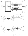
- Fig. 2 shows a cross-sectional view of two variants of the micro flow system 1 manufactured utilising semiconductor technology.
- the micro flow system may be manufactured in any suitable material such as polymers, glass, semiconductors, such as silicium, germanium, gallium arsenate, etc., etc.
- the first micro flow system (a) shown is a 3-layer sandwich.
- the central layer 14 is a silicon wafer having a flow channel 5 etched into it.
- the silicon wafer 14 is covered with a transparent plate 15, such as a glass plate, having a thickness of, e.g., 0.16 ma. Fluids inside the flow channel 5 may be observed through the glass plate 15, e.g. utilising a microscope 16 (detection means).
- the fluid inlet 2 and outlet 7 are connected to tubings 17, 18, e.g. fused silica capillary or Teflon tubings, for entering fluids into or discharging fluids from the flow channel 5. Buffer inlets 3 and 4 and the outlet 6 for the separated particles are not shown.
- a modified version (b) of the micro channel system for separation was designed with gravitation as the force field, thus sorting particles due to their density and/or diffusion constant, the latter mainly being controlled by the shape and size of the particles.
- the system is during operation positioned with the flow plane substantially perpendicular to the direction of the force of gravity.
- this embodiment of a micro flow' system 1 has a sample inlet port 2 and an outlet port 7 located above the micro channel 5 and a buffer inlet port 3 and an outlet port 6 located below the micro channel 5.
- the sample containing particles 9 enters the separation flow channel through inlet port 2, and a guiding buffer 10 enters the separation flow channel 5 through inlet port 3.
- the micro flow system may comprise two further inlet ports for entering a second and a third guiding buffer into the micro channel 5, where the two further inlet ports are positioned above the micro channel, one on each side of the sample inlet port 2.
- the flow rates of the sample and the second and third guiding buffers may be adjusted so that the particles contained in the sample are lined up in a single line.
- Characteristic features of an exemplary embodiment of a micro flow system according to the invention is shown in Table 1.
- Characteristics, micro flow system Manufacturing method Material Silicium Oxide, SiO 2 Photo-lithography Wet-chemical etching Flow Channel Cross sectional area 0.1 - 0.55 mm width x 0.04-0.2 mm depth Length 1.0 - 200 mm Total flow rate [ ⁇ l/min] 1 - 200 Flow velocity [mm/min] 15 - 180 Reynolds number 0.1 - 20 Separation time 0.1 sec - 6.0 sec [2 ⁇ l/min] Magnet Permanent Magnet Rare Earth Samarium-Germanium 0.5 x 0.5 x 0.2 mm Electromagnet Holding Magnet 25 mm 12 V D.C. RS
- Fig. 3 shows a micro flow system 1 utilising electrodes 20, 21 to generate an electric field across the flow channel 5.
- the electrodes 20, 21 may introduce dielectrophoretic or electrophoretic forces utilised for particle separation.
- gold electrodes may be positioned at the inside of the walls of the flow channel 5.
- an electrical field is generated substantially perpendicular to a longitudinal axis of the flow channel. The electrical field cause deflection of charged particles or molecules in the flow channel 5 whereby electrically charged particles can be deflected away from the sample containing particles flowing in the micro flow channel and into a guiding buffer also flowing in the flow channel and abutting the sample containing particles in the micro flow channel.
- Fig. 4 shows a micro flow apparatus 22 including a micro flow system 1 as shown in Figs. 1 and 2.
- the micro flow system 1 has two inlets 2, 3 and two outlets 6,7, two syringe pumps 23, 24, two 3way control valves 25,26 and capillary tubings 27, 28.
- the capillary tubings 27, 28 are used for interconnecting the two syringe pumps 23, 24 with the inlets 3, 2, respectively, of the micro flow system 1.
- syringe pumps with means, e.g. stepping-motors (not shown), to move the pistons at a predetermined speed have been utilised for generating a continuous flow of the guiding buffer through the inlet tube 27 and a continuous flow of the sample through the inlet tube 28.
- the system can be operated in a first loading mode where the two 3-way control valves 25, 26 open for flow between the syringe pumps 23, 24 and the buffer reservoir 29 and the sample reservoir 30, respectively, and the syringe pumps 23, 24 are loaded with buffer and sample from the reservoirs 29, 30, respectively.
- the two 3-way valves 25, 26 open for flow between the syringe pumps 23, 24 and the capillary tubing 27 to the buffer inlet 3 and the capillary tubing 28 to the sample inlet 2 of the micro flow system 1, respectively.
- the syringe pumps are in this second operational mode controlled to generate a predetermined volumetric flow rate through the micro flow system 1.
- Fig. 5 illustrates various micro flow systems 31, 32, 33, 34, 35, and 36 having flow channels of different geometries, illustrating different embodiments of the invention.
- Micro flow systems with two or three inlet ports and two, three or five outlet ports, respectively, are shown in Figs. 5(a)-(d).
- the system shown in 5(a) with inlet ports for sample and two guiding buffers, respectively, and sort outlet port and waste outlet port is similar to the system shown in Fig. 1.
- Figs. 5(b) and (c) show systems with multiple outlet ports, three and five, respectively, whereto particles can be sorted and leave the flow channel through according to their susceptibility to the applied field.
- a simple system with two inlet and two outlet ports are shown in Fig.
- FIG. 5(d) similar to the one in Fig. 2(b) that is used for gravitational sorting.
- a micro flow system with a separation channel equipped with a magnet where the width of the separation channel is enlarged before the bifurcation in a sort outlet and a waste outlet is shown in Fig. 5(e).
- the size of the cross-sectional area occupied by the sample flow is proportional to the width of the separation channel.
- the transversal distance between two particles A and B is increased proportional to the increase of the width of the separation channel.
- a larger distance between particles, which are to be separated yields a higher selectivity of the mechanical separation.
- Fig. 5(f) shows a micro flow system where the width of the outlet channel 6 is increased to form a chamber where the sorted particles are collected for further processing or analysis, e.g. detection, staining, destaining or cultivation.
- Fig. 6 illustrates a system in which particles are entrapped inside the micro flow channel 5 for a desired period using the electromagnet-equipped apparatus.
- the magnetic field is adjusted so that magnetic particles 12 are drawn to the inner wall of the micro flow channel 5 close to the electromagnet 8.
- the particles 12 are redispersed and are rapidly moved to the sorting outlet port 6.
- This 2-step sorting procedure is an alternative to the continuous sorting procedure that is particularly useful in sorting of extremely rare events where dilution of the sorted cell fraction could be a problem.
- the sorting outlet port 6 may be closed when the current to the electromagnet 8 is turned on and is open when the current to the electromagnet 8 is turned off.
- the figure shows magnetic particles 12 in the process of being withdrawn from a continuous sample flow 9.
- the magnetic particles 12 are attracted by the magnetic field and withdrawn from the sample flow 9 by precipitation at the inner wall of the micro flow channel 5 proximate to the electromagnet 8.
- the magnetic particles 12 are released into the flow again.
- the separation flow channel may not have a sort outlet, instead a buffer may enter the micro flow channel 5 after the sample and the entrapped particles may be released by removing the current supplied to the electromagnet 8.
- Fig. 7(a) shows two flow channels 45, 46 operating in parallel.
- the sample containing particles enters the flow channels 45, 46 through inlet ports 47, 48, respectively.
- the guiding buffer enters the flow channels through the inlet ports 49, 50, respectively.
- particles susceptible to the magnetic field generated by magnets 51, 52, respectively are deflected from the sample containing particles into the corresponding guiding buffer and flow thereafter through the sort outlet 53.
- the remaining part of the sample leave the flow channels 45, 46 through the waste outlets 54, 55, respectively. Separation is increased by using a plurality of flow channels coupled in parallel.
- Fig. 7(b) and (c) shows examples of combinations of micro flow systems for magnetic, hydrodynamic or gravitational separation.
- particles are first separated from a sample in a magnetic separation channel, where after the sorted particles are subjected to a hydrodynamic separation due to the optical properties of the particles.
- a hydrodynamic separation due to the optical properties of the particles.
- two magnetic separation channels are coupled in series in order to obtain a highly purified product.
- Fig. 8 illustrates an example of a micro flow system having means for automated labelling of particles with fluorescence or magnetic probes.
- the system may be combined with post-treatment means for removal of the probes or for other treatment of the sorted particles.
- the system contains a micro flow system containing a channel 57 for addition of liquids to the sample, e.g. reagents for cell lysis or staining, a channel 58 for incubation and cultivation or storage of the sample for further processing and a separation channel 5.
- a sample is introduced into the micro flow system via an inlet 2 and one or more reagents can be added continuously to the sample, which is transported into the incubation channel 58.
- a simple micro flow structure was constructed for sample pre-treatment.
- the flow rates are managed by computer-controlled syringe pumps.
- the incubation period between mixing and analysis of the sample is given by the volumetric flow rate of the syringe pumps and the cross-sectional area and length of the incubation channel.
- Fig. 9 shows a micro flow system manufactured as a 3-layer sandwich.
- the central layer is a silicon wafer having a flow channel etched into it.
- the silicon wafer is covered with a transparent plate, such as a glass plate, having a thickness of, e.g., 0.16 mm. Fluids inside the flow channel may be monitored through the glass plate, e.g. utilising a microscope or other optical detection means.
- the fluid inlet and outlet are connected to tubings, e.g. fused silica capillary or Teflon tubings, for entering fluids into or discharging fluids from the flow channel. Buffer inlets and the outlet for the sorted particles are not shown.
- the bottom plate e.g. made of plastic, facilitates mounting of the tubings.
- Figs. 9(1) to (5) illustrates the following description of the manufacturing and preparation of a micro flow system.
- a separation flow channel was designed to fit into a system comprising a bonded silicon/glass sandwich.
- the micro channels were etched into a silicon wafer covered with a boron glass plate having a thickness of 0.2 mm allowing monitoring of the micro channels, using i.e. a microscope.
- the separation flow channel was fabricated on a 4", 350 ⁇ m, ⁇ 100> silicon wafer.
- a 1.5 ⁇ m layer of SiO 2 was applied to the surface of the silicon wafer and was patterned with a mask containing the channel layout.
- a 2.6 ⁇ m layer of photoresist was spun on top of the SiO 2 and patterned with a mask defining intermediate holes.
- the two-step mask consisting of a SiO 2 mask and a photoresist mask was used for etching a two level structure with vertical walls by reactive ion etching (RIE) in a SF 6 :O 2 plasma.
- RIE reactive ion etching
- the holes were initially etched to a depth of 22 ⁇ m and then etched deeper together with the channels, which were etched to depths in the range from 40 ⁇ m to 100 ⁇ m
- a layer of 1.8 ⁇ m SiO 2 was patterned with a mask for inlets and outlets on the back of the silicon wafer.
- the etching was carried out in KOH at 80°C and was stopped when all the intermediate holes were clearly visible from the back.
- a glass wafer was anodically bonded to the silicon wafer.
- the micro channels were designed for volumetric flow rates of 0.1 to 200 ⁇ l/min with a mean flow speed of maxmum 100 (mm/min).
- the separation flow channel may be provided with one or two permanent or electromagnets in three different ways:
- Example 1 the micro flow system used in Example 1 has also been tested by utilising it for separation of Human T-lymphocytes (JURKAT cells).
- JURKAT cells Magnetically stained and unstained JURKAT cells were used to form a heterogeneous cell sample.
- a CD4-magnetic surface marker from Miltenyi Biotech was used. JURKAT cells were suspended in 1% PBS/BSA to a concentration of 10 7 /ml. Biotin-conjugated CD4 magnetic microbeads were added at 2 ⁇ l stock/10 7 cells following the manufacturer instruction.
- the system employed for separation of magnetisable particles from a sample is shown in Fig. 4. It comprises two syringe infusion pumps (Harvard Apparatus, Southnatik, Az) that provides constant flow rates of 0.1 to 100 ⁇ l/min using a 0.5 ml micro syringe (Hamilton, Bonaduz, Switzerland), a separation flow channel of silicon for the separation of the magnetisable particles, and a collecting unit for collecting of the sorted particles.
- Two 3-way microvalves (Lee, Parameter AB, Sweden) were integrated into the apparatus for sterile solution handling. All components were interconnected with fused silica capillaries (340 ⁇ m id., Supelco, U.S.A.).
- the SFC was placed under an inverted microscope (Axiovert 100, Zeiss, Germany) for visualisation of the separation procedure. All micro channels and tubing were deactivated by silanisation as described in Blankenstem, G. Scampavia L, Branebjerg J, Larsen UD, Ruzicka J (1996): Flow switch for analyte injection and cell/particle sorting in Analytical Methods and Instrumentation, ⁇ TAS'96 conference, 17-22 November 1996, Basel.
- a FACScan with 488 nm argon laser excitation and collection of forward and side scatter and fluorescence of fluorescein were used (Becton Dickinson, Mountain View, CA) for all experiments. Results were collected and analysed using the FACScan research software (Becton Dickinson).
- Fig. 10 Results on the use of a separation flow channel equipped with a permanent magnet optimised for Dynal beads are shown in Fig. 10.
- About 1 ml of the non-magnetic, non-deflected fraction was collected at the waste outlet and analysed by flow cytometry (B). To enumerate the positive and negative fractions, two windows were set for the statistic evaluation. Before separation, the sample contained 38.3 % fluorescence particles and 55.8 % magnetic particles, respectively (a).
- This example concerns enrichment of fetal cells in a sample for magnetic activated cell sorting.
- a combination of optical cytometry, and Figs. 4 and 8 (lower), magnetic cell separation, provides a powerful apparatus for efficient enrichment of fetal cells in a sample.
- the process for increasing the concentration of fetal cell in maternal blood samples involves the following steps (see Fig. 11): (i) A first selection step for removal of the majority of the maternal blood cells based upon their volume, size and density; (ii) A second sorting step for isolation of the fetal blood cells from the remaining maternal blood cells based on immuno-fluorescent separation and/or based on immuno-magnetic separation using a device as described in Fig. 4.
- the magnetic blood sample is first separated in a magnetic separation chamber, followed by a separation due to optical properties of the sample, or two magnetic separations are performed one after the other, see Fig. 7(c), in order to obtain a highly purified product.
- Nucleated red blood cells are found in maternal blood in a concentration of 10 to 1000 per ml of all nucleated cells. Bianchi has shown (D.W. Branchi, Journal of Pediatrics, 1995, 127, 6, p. 847-856) that it is possible to use such cells for genetic screening in prenatal diagnosis.
- the cell surface marker CD71+ for example, is an appropriate marker to select such cells from maternal blood.
- Test results demonstrates that magnetic activated cell sorting is powerful enrichment system for sorting and isolating fetal nucleated blood cells from maternal blood. For this the magnetic activated cell micro technology as described in this invention is used.
- Fetal cells are distinguished and separated from maternal blood by the use of a specific surface marker (CD71) which is only present on the cell membrane of fetal nucleated blood cells.
- CD71 specific surface marker
- This example concerns depletion of magnetically labelled CD45 positive cells (maternal leukocytes) from a maternal blood sample spiked with cord blood.
- a flow chip described in Fig. 1 was used in a system as described in Fig: 4.
- a 1:3 spike fetal/maternal, v/v
- Heparin was used as an anti-coagulant.
- the nucleated cells were labelled with CD45 coated magnetic 0.1 ⁇ micro particles (Immunicom, U.S.A.), using a monoclonal antibody against CD45 as the first layer.
- the cell suspension was collected at both outlets 6 and 7 (see Fig. 1).
- parts of both the collected fractions were analysed on microscope slides. The results showed that most of the cells, more than 95%, collected at the sort outlet 6 were CD45 positive.
Abstract
Description
- The present invention relates to methods and apparatuses for detection, separation, sorting, and analysis of particles, such as cells, cell organelles, beads, molecules, such as Deoxyribonucleic acid (DNA), proteins, etc. in a fluid. In particular, the invention relates to particle separation by using different forces such as magnetic, electrophoretic, hydrodynamic and/or gravitational forces, e.g. for utilisation in flow cytometry, light microscopy, electrophoretic separation, magnetophoresis, etc.
- Flow cytometry is a well known technique that is used for high throughput measurements of optical and/or electrical characteristics of microscopic biological samples. Flow cytometry instruments analyse and isolate cells and organelles with particular physical, biochemical, and immunological properties.
- Traditionally, cell sorting by flow cytometry (fluorescence activated cell sorting) has been the method of choice for isolation of specific cell populations by surface markers. However, cell sorting by flow cytometry suffers from several drawbacks, especially high dilution of desired cell sample, low speed and sterility problems. Furthermore, the equipment is very costly with high operation and maintenance cost, making the technique available only to a limited number of laboratories.
- During the last few years, isolation of cells by antibody-coupled magnetic beads and carriers has been developed into a reliable tool for the isolation and characterisation of cell populations. Immunomagnetic cell separation, e.g. as commercially introduced by Dynal A/S and Miltenyi Biotec, has become an established method for cell analysis in clinical diagnostics Due to the relatively low prize, this method is attractive in flow cytometry, especially in sorting of rare cellular events. For example, sorting of fetal cells contained in maternal blood sample provides a non-invasive alternative to prenatal diagnostic procedures, such as amniocentesis of chorionic villus sampling. Another rare event scenario is the detection of low conçentration of cancer cells which has an important role in diagnosis of minimal residual disease and evaluation of appropriate therapies. Another medical application for cell sorting systems is the diagnosis of bacterial and viral diseases.
- Although this method offers relatively inexpensive approach to sort rare cellular event, it adds considerable time onto the overall rare event detection and it does not offer the multiparameter analysis readily available with flow cytometry techniques. Existing techniques for magnetic separation are suffering from the low purity of the sorted cell fraction and the low recovery rate of the sorted cells. In most systems several washing steps have to be implemented into the separation procedure which then causes cell losses. Additionally small subpopulation of labelled cells cannot be directly isolated by existing magnetic separation techniques.
- Separation of magnetic particles from a fluid containing the particles by means of a magnetic field is known in the art and is disclosed e.g. in Ahn, C.H et al: "A Fully Integrated Micromachined Magnetic Particle Manipulator and Separator", Proceeding of the workshop on micro electro mechanical systems (Mem, Oiso, Jan. 25-28, 1994, no. Workshop 7, 25 January 1994, Institute of Electrical and Electronics Engineers, pages 91-96) and in US 5,053,344. No control of the transverse position of the particles in the flow channel is indicated in any of the examples and several particles may be present at the same longitudinal position at different transversal positions.
- Likewise is the separation of particles from a fluid by means of an electric field known in the art as disclosed in e.g. US 4,279,345 according to which droplets are generated from the fluid containing the particles, a parameter of the particles in the droplets is observed and some of the particles are deflected by means of an electrostatic field in accordance with the observed parameter.
- It is also known from US 3,827,555 to enclose a fluid containing particles in a liquid sheath so that the particles pass a detector one at a time. Particles are lead to a sort outlet instead of the ordinary outlet by means of diverting the fluid containing the particles as well as the liquid sheath to the sort outlet.
- A good overview about fluorescence activated cell sorting procedures and magnetic activated cell sorting is given in Melamed et. al., "Flow Cytometry and Sorting, (Ed. Melamed et. al., Wiley & Sons Inc., 1990).
- Advances in microfabrication and microfluidic technologies continue to fuel further investigation into the miniaturisation of bioanalytical instruments and biochemical assays in general. The present invention relates to development of a low cost non-invasive diagnostic test method and devices for carrying out such tests that include measuring, monitoring, sorting and analysing samples containing particles, such as organic cells, microbeads, cell organells and macromolecules such as DNA. The present invention provides a cheap, fast and reliable method and devices for handling, sorting and analysis of such particles.
- Separation may be performed according to various physical properties, such as fluorescent properties or other optical properties, magnetic properties, density, electrical properties, etc. According to an important aspect of the invention, particle separation is performed by aligning the particles in one row of particles in a micro flow channel so that particles can be treated individually.
- Thus, it is an object of the present invention to provide a micro flow system and a method of particle separation having an improved efficiency of particle separation compared to the prior art.
- It is another object of the present invention to provide a micro flow system and a method for particle separation in which cell lysis is minimised.
- It is yet another object of the present invention to provide an improved method for preparation of fluids containing particles for separation and analysis of the particles.
- It is a still further object of the present invention to provide a micro flow system and a method for simultaneous separation of particles into a plurality of groups of particles
- It is a still further object of the present invention to provide a micro flow system including facilities for pre-treatment and/or post-treatment of a sample.
- It is a still further objective of the invention is develop a system for separation and analysis of fetal cells in whole maternal blood samples using an integrated automated micro flow system. The system is designed by downscaling and combining different methods for handling, manipulation and analysis of biochemical samples. Thus, prenatal diagnostics by analysis of fetal cells separated from a whole maternal blood sample is an area, which can benefit from advances in miniaturisation.
- It is another objective of the invention is develop a system for separation and analysis of cancer cells from a sample containing cancer cells and healthy cells using an integrated automated micro flow system. The system is also designed by downscaling and combining different methods for handling, manipulation and analysis of biochemical samples. Thus, cancer diagnostics by analysis of cancer cells separated from healthy cells is also an area which can benefit from advances in miniaturisation.
- According to a first aspect of the invention the above and other objects are fulfilled by a micro flow system for separating particles, comprising a member having
- a flow channel defined therein for guiding a flow of a fluid containing the particles through the flow channel,
- first inlet means positioned at one end of the flow channel for entering the fluid into the flow channel,
- second inlet means for entering a first guiding buffer for controlling cross-section and flow path through the flow channel of the flow of the fluid containing particles,
- first outlet means positioned at the other end of the flow channel for discharging the fluid from the flow channel,
- the flow of the fluid containing the particles being controlled in such a way that one particle at the time passes a cross-section of the flow channel,
- the member being positioned in a field that is substantially perpendicular to a longitudinal axis of the flow channel so that particles residing in the flow channel and being susceptible to the field across the flow channel are deflected into the first guiding buffer in the direction of the field.
-
- According to a second aspect of the invention the above and other objects are fulfilled by a method of separating particles, comprising the steps of
- guiding a flow of a fluid containing the particles through a flow channel with a guiding buffer in such a way that one particle at the time passes a cross-section of the flow channel,
- positioning the flow channel in a field that is substantially perpendicular to a longitudinal axis of the flow channel so that particles residing in the flow channel and being susceptible to the field across the flow channel are deflected in the direction of the field and thereby separated from the fluid containing particles and into the guiding buffer.
-
- According to a preferred embodiment of the invention, a method of separating fetal cells from maternal cells, comprising the steps of selective magnetically staining of fetal cells in a fluid containing fetal and maternal cells, guiding a flow of the fluid containing the fetal cells through a flow channel in such a way that one fetal cell at the time passes a cross-section of the flow channel, positioning the flow channel in a magnetic field that is substantially perpendicular to a longitudinal axis of the flow channel so that magnetically stained fetal cells residing in the flow channel are deflected in the direction of the magnetic field.
- Further a method is provided for separating cancer cells from other cells, comprising the steps of selective magnetically staining of cancer cells in a fluid containing cancer and other cells, guiding a flow of the fluid containing the cancer cells through a flow channel in such a way that one cancer cell at the time passes a cross-section of the flow channel, positioning the flow channel in a magnetic field that is substantially perpendicular to a longitudinal axis of the flow channel so that magnetically stained cancer cells residing in the flow channel are deflected in the direction of the magnetic field.
- The particles to be separated from other particles in a fluid and/or to be separated from the fluid containing the particles may comprise living cells, chromosomes, organelles, beads, biomolecules, such as Deoxyribonucleic acid (DNA), proteins, etc.
- Preferably, the flow through the flow channel is a laminar flow so that flow of particles are predictable and easy to control, e.g. with a flow of guiding buffers.
- When the flow is laminar, the stream of particles can be positioned as desired within the flow channel, e.g. by controlling flow velocities of the fluid containing particles at the particle inlet of the member and flow velocities of guiding buffers at corresponding inlets.
- Preferably, the flow channel is small for the flow through the channel to have a low Reynolds number, e.g., in the range of 0.01-500, such as 0.05-50, preferably 0.1-25. Thereby, inertial effects, which causes turbulence and secondary flows are negligible, viscous effects dominate the dynamics, and mixing is caused only by diffusion. Flow of the sample, which is the fluid containing particles and guiding buffers can be laminated in guided layers through the channel and displacement of particles in the channel is only caused by the external force applied. The Reynolds number referred to is based on the hydraulic diameter of the flow channel, the flow velocity in the axial direction and the fluid density and viscosity, Re=ρDh/µ where the hydraulic diameter Dh is defined as four times the cross-sectional area divided by the wetted perimeter.
- The illustrated flow channels of the micro flow system have a width ranging from 0,1 to 0.65 mm, preferably ranging from 0.1 to 0.4 mm, in particular ranging from 0.1 to 0.2 mm, and a depth ranging from 0.04 to 0.2 mm, preferably ranging from 0.04 to 0.1. With respect to the lowest cross-sectional area of the flow channel, it is preferred that this area is in the range of 0.004 to 0.11 mm2, in particular in the range of 0.004 to 0.02 mm2.
- It is believed that any length of the flow channel within the range of 0.1 to 20 mm, preferably 1.0 to 3.5 mm, would lead to satisfactory results.
- Preferably, the system is operating with total volumetric flow rates of 0.1 up to 200 µl/min, which gives a flow velocity of 15 mm/min up to 180 mm/min. The average residence time of a particle inside the flow channel, which corresponds to a separation time ranging from 0.1 to 6 sec. The residence time of the sample is defined by the total volumetric flow rate of the system.
- The micro flow system may comprise flow rate adjustment means for adjustment of the time the particles reside in the flow channel.
- Preferably, the fluid channel is sized so that for efficient separation, particles are displaced 10 - 30 µm in the flow channel. Thereby, the particle may only be exposed to a field for a very short period of time and thus, continuous separation of particles may be facilitated.
- In order to collect the particles, which are deflected in the flow channel, the micro flow system may further comprise second outlet means for discharging particles having been deflected in the flow channel.
- The micro flow system comprises second inlet means for entering a first guiding buffer into the flow channel together with the fluid containing particles. When the flow is laminar, the two fluids flow through the flow channel in parallel abutting each other along a small area extending along a longitudinal axis of the flow channel whereby the cross-section and the path through the flow channel of the flow of the fluid containing particles may be controlled by the first guiding buffer flow. Further, particles in the fluid containing particles may be deflected into the guiding buffer fluid when the two fluids pass the field essentially perpendicular to the longitudinal axis of the flow channel. Furthermore, two (or even more) outlets may be provided at the down stream end of the flow channel for discharging the guiding buffer now containing separated particles and fluid substantially without particles susceptible to the field essentially perpendicular the flow channel, correspondingly.
- The micro flow system may further comprise third inlet means for entering a second guiding buffer for improved control of the path of particle flow through the flow channel. By adjustment of the flow velocities of the guiding buffers and the fluid containing particles, the flow within the flow channel of fluid containing particles may be controlled to flow within an essentially cylindrical shaped domain with a longitudinal axis extending substantially parallel to a longitudinal axis of the flow channel and further the position within the flow channel and the diameter of the flow cylinder may be controlled by corresponding adjustments of the volumetric ratio between the flow rate of the fluid containing particles and the flow rate of the guiding buffers.
- It is possible to control the cross-sectional area of the domain containing the sample to be a little larger than the cross-sectional area of the particles by adjusting the volumetric flow rates of the sample and of the one or two guiding buffers in such a way that the particles contained in the sample are aligned in a single row of particles. This is a very important feature since it enables individual treatment of each particle and it leads to a sensitive method of sorting particles according to their susceptibility to a field. A sample flow layer thickness less than 1 µm may be achieved.
- Preferably, the channel depth is small enough, e.g. below 50 µm, to allow observation of the particles flowing through the channel by a microscope. In an important embodiment of the present invention, the micro flow system comprises a cover, e.g. a transparent or translucent cover, for covering the flow channel. When the cover is transparent or translucent, it will be possible to observe events in the flow channel, e.g. passage of a stained or coloured particle or cell.
- The member with the flow channel may be produced from any suitable material, such as silicon, polymers, such as Plexiglas, Teflon, etc., glass, ceramics, metals, such as copper, alumna, stainless steel, etc., etc.
- The channel may be provided in the member by any suitable manufacturing process, such as milling, etching, etc.
- In a preferred embodiment of the invention, the member is a silicon chip manufactured utilising photolithography and the channel is etched into the silicon chip.
- The field may be a magnetic field, an electric field, a gravity field, etc., and any combination of such fields.
- A magnetic field may be generated by permanent magnets, such as rare earth magnets, such as samarium-germanium magnets, a mixture of ferromagnetic powder and epoxy, etc., etc., electromagnets, e.g., in silicon integrated electromagnets, etc. The magnets are preferably positioned adjacent to the flow channel so that the magnetic field is substantially perpendicular to a longitudinal axis of the flow channel.
- In a preferred embodiment of the invention, the magnets are positioned in and glued to rectangular slots that are etched into a silicon chip. The slots are located adjacent to the separation flow channel. In the example shown in Fig. 1, a permanent magnet or an electromagnet can be received by slots in the micro flow system. The slots are, e.g., 0.5 mm wide, 0.5 mm long and 0.2 mm deep. For generation of a magnetic field, a solid magnetic block, i.e. rare earth magnet can be glued into the slot. Alternatively, a mixture of ferromagnetic powder and epoxy can be injected into the slots to produce a high magnetic field gradient.
- The strength of the magnetic field inside the micro flow system may be adjustable. If an electromagnet is used for generation of the magnetic field, the magnitude of the field may be varied by varying the amplitude of the voltage input to the electromagnet. If a permanent magnet generated the magnetic field, the magnitude of the field may be varied by varying the distance between the magnet and the flow channel of the micro flow system.
- As already mentioned, the net displacement of a particle in the micro flow system depends on the force applied to it by the field. This can be utilised for separation of a first group of particles of various types in a fluid into a plurality of set of particles; each set comprising a specific type of particles. A micro flow system with e.g. five separation outlets may be used to separate a fluid containing particles into five sets of particles, each set comprising particles that are influenced by the field with a force of a specific magnitude, in the following denoted particles with a specific F-value. Particles with a low F-valuc are only deflected by a small amount by the field and are discharged from the flow channel through a corresponding outlet port. Particle deflection is increased with increasing F-values whereby such particles are discharged from the flow channel through the corresponding other outlets.
- The particles to be separated from other particles in a fluid and/or to be separated from the fluid containing the particles may be magnetically stained to facilitate separation in a magnetic field.
- In the present context, the term staining is to be understood in a broad sense. The term is intended to cover any way of marking a particle thereby facilitating detection of the particle. For example a cell may be stained with a fluorescent substance, such as acridin orange, methylene blue, etc, facilitating detection of the stained particles by a fluorescence detector, or, a particle is said to be magnetically stained when it is coupled to a magnetic microbead. The microbead may for example carry a monoclonal or polyclonal antibody on its surface for coupling to an antigene of a cell to be separated utilizing a magnetic field.
- In the case where particles have to be detected in a flow channel by optical means, such particles are preferably stained with a chromophoric reagent, or, a fluorescent probe.
- An electric field may be generated by electrodes, such as metal electrodes, such as gold electrodes, etc. The electrode may be positioned inside the flow channel, e.g. to introduce electrophoretic forces, e.g. for separation of charged molecules in the fluid, or outside the flow channel e.g. to introduce dielectrophoretic forces, e.g. for separation of particles contained in the flow according to the susceptibility of the particles to the field. Preferably, the electrodes are positioned in such a way that the electric field is essentially perpendicular to a longitudinal axis of the flow channel.
- The electric field may be a high frequency field, e.g. a 5 MHz field generated by electrodes positioned inside the flow channel. Living cells positioned in an electric field will be polarized and will be influenced by the field and thus, an alternating field may be used to separate living cells from other particles.
- The field generated across the flow channel may be utilised for immobilisation of particles whereby particles may be held in substantially fixed positions within the flow channel for a specific period, e.g. as outlined in Fig. 6, allowing chemical reactions with the particles to take place and/or kinetic measurements on the particles to be performed and/or to bring the particles into contact with different chemical substances or for separating the particles from the sample. The particles may undergo a washing step before removal or reduction of the field redisperses them.
- According to another embodiment of the invention, the flow through the sort outlet is not continuous but only allowed by a controlling means, e.g. a valve, when a particle with the desired characteristics is detected by a detection means. The particles are sorted using hydrodynamic forces in the sense that the flow is diverged from the ordinary outlet to the sort outlet only when it contains a particle that fulfils certain criteria. The concentration of sorted particles in the flow out of the sort outlet will consequently be high. This is especially an advantage for sample flow with rare occurrence of particles that are searched for. The detection means can be e.g. optical detection means or magnetic detection means e.g. a Hall sensor or means for detecting e.g. electrical or other properties of the particles. The detection means can in an alternative embodiment be used for counting of particles with the desired characteristics as a separate function or in connection with any of the other embodiments described herein.
- In yet another embodiment, the field strength is adjustable, e.g. by adjusting the voltage supplied to an electromagnet or to a set of electrodes or by adjusting the distance from a permanent magnet to the flow channel. Particles are in a first operation mode entrapped inside the flow channel by the field at high intensity while at the same time the sort outlet is closed. In a second operation mode, the field is reduced and the sort outlet is open in such a way that the entrapped particles are redispersed and moved out of the sort outlet. Particles that are rare in the sample can by switching between these two operational modes be sorted out in a highly concentrated form. An example of this embodiment is outlined in Fig. 6.
- In a further interesting embodiment, the micro flow system according to the invention involves facilities for performing pre-treatment and/or post-treatment of the fluid comprising the particles. These possibilities are outlined in Figs. 5(f), 7 and 10. As an example, the particles may be treated with a reagent before entering the flow channel, e.g. undergo magnetic or chromophoric staining. Post-treatment may comprise means for collecting or concentrating the deflected particles or means for contacting the deflected particles with one or more reagent(s).
- By one possible combination of the pre-treatment and the post-treatment facilities, cells may undergo magnetic staining before entering the flow channel, and after separation the staining may be removed by treatment of the stained cells with a suitable reagent.
- It is an important advantage of the present invention that a micro flow system is provided that operates continuously with no requirement for operator intervention.
- It is another advantage of the present invention that separation may be performed in one step.
- It is still another advantage of the present invention that the particles can be separated in a continuous flow without substantially interfering with the flow itself and that separated particles may be collected at corresponding separated outlets of the flow channel without having to interrupt the flow in the flow channel.
- It is another important advantage of the invention that the particles contained in the sample by the adjustment of the flow rate of one or more guiding buffers can be lined up in one row such that the particles can be analysed and sorted individually. This results in a sorting system with the highest sensitivity to the susceptibility of the single particle to the field applied to the sorting channel and a sorting system with the highest resolution of the detection means of the characteristics exhibited by the particles.
- It is yet another advantage of the present invention that the micro flow system is easily integrated into other continuous flow systems, such as flow cytometers, flow injection analysis systems, etc.
- It is a further advantage of the present invention that particles may be separated into a plurality of groups of particles, e.g. different subpopulations of cells, based on different susceptibility to the field generated across the flow channel of the different groups of particles. This may be obtained by using a multiple outlet micro flow system as outlined in Fig. 5(c).
- It is a still further advantage of the present invention that the micro flow system allows observation of particles in the flow channel using a microscope.
- It is a still further advantage of the invention that a closed system is provided allowing biohazardous samples, such as samples containing pathogens, to be entered into the system without contaminating the laboratory environment and without causing hazard for operators working with pathogen biomaterials.
- It is a still further advantage of the invention that a system with a low shear stress in the flow is provided allowing a gentle treatment of biological samples; e.g. fragile living cells, especially when two guiding buffers are introduced in the channel.
- It is a still further advantage of the invention that a high concentration of the sorted particles can be obtained even from samples with rare occurrence of particles that are searched and sorted for.
- According to an important aspect of the invention, a new system for immunomagnetic cell separation and manipulation is provided that utilises a silicon based micro fabricated flow chip. The system combines the advantage of flow cytometry and immunomagnetic separation technique. The flow chip will be an important component of a portable micro system for cell sorting and analysis. The flow chip is designed for rapid immunomagnetic cell separation nearly without any pressure drop. Its simple and cheap fabrication and versatile sorting and detection properties offer an alternative to conventional cell separation systems.
- It is an advantage of the invention that a micro flow system is provided that is cheap, easy to operate, versatile, simple and portable and that offers the possibility of automation.
- A miniaturised flow channel system is provided that utilises the advantageous fluid behaviour in micro systems. The invented system operates continuously. Instead of holding back the magnetisable particles in the separation unit, the particles are deflected into the direction of the magnetic field while passing it continuously. By splitting the fluid flow into two or more outlets, the deflection of the particles can be used for separation of particles into different sets of particles, each of which leaves the flow channel through a specific outlet.
- The continuous separation system (CSS) allows efficient enrichment as well as depletion of lahelled sample contents of interest. The CSS is designed to fit under a microscope allowing parallel detection of the optical properties of the sample and the control of separation of particles.
- An advantage of the geometry of the invented separation flow channel is that a magnetised or electrically charged particle has to be moved only over a distance of 10 - 30 µm to be separated from the fluid containing particles.
- Furthermore, the invention enables isolation of multiple cell or particle subpopulations from a single sample at the same time. The magnitude and direction of the force F on a magnetisable particle, e.g. a magnetically labelled cell, is dependent on the magnitude of the magnetic field and the number of magnetic moments inducible on a labelled cell.
- F = N*S *µB* grad B
where S is the number of Bohr magnetons (µB) per particle and N is the number of particles per cell. - Beads with small S are moving a less distance in lateral direction in relation to the flow through the flow channel than beads with a higher S value. This can be used to separate subpopulation of cells labelled with different magnetisable beads: By splitting the flow channel in various outlet channels cells can be distinguish and separated due to their individual F values.
- The drag force on a spherical particle can be found from the particle Reynolds number, based on particle diameter, particle velocity relative to the fluid and fluid viscosity and density. In a flow with a Reynolds number less than 100, the drag force D on the particle can be found from a modified version of Stokes law
- An example is given for separation by gravitational means. The effective gravitational force G defined as the gravitational force minus the buoyancy force is found as
- The velocity to a given time t can be found as
- For a particle submerged in water with a diameter of 30 µm and a density of 1.2 times the density of water the settling velocity is 9 x 10⁻⁵ m/s. The particle will reach 90 % of this velocity after 2.1 x 10⁻⁵ seconds why the transient phase can be neglected. It will take the particle 0.33 seconds to travel a distance of 30µm, which makes the method reasonable to employ for separation purposes.
- While instrumentation in chemistry and biochemistry has become more automated in recent years, the preparation of samples remains a highly laboratory intensive task. The demand is increasing for high throughput, easier to use cost effective analytical devices and assays. Creating this opportunity is e.g. the world-wide effort to sequence the Human Genome, resulting in the development of new DNA diagnostics and therapeutics. Another important trend is the minimisation of health care costs and hospital admissions by testing patients and monitoring therapeutic use in less expensive environments, the so-called point-of-care analysis.
- Micro flow devices containing arrays of nucleic acid hybridisation, sites, known as genosensors, are being developed for a variety of uses in genomic analysis. A great deal of the overall genosensor development effort involves optimisation of experimental conditions in the actual use of genosensors.
- Exemplary embodiments of the invention will now be described with reference to the accompanying drawings in which
- Fig. 1 illustrates the operation of particle separation according to the present invention,
- Fig. 2 shows a cross-sectional view of a separation flow channel according to the present invention. (a) shows the main embodiment and (b) shows a cross-sectional view of a separation flow channel for gravitational separation,
- Fig. 3 shows a micro flow system with electrodes as field generating means,
- Fig. 4 shows a flow diagram of a magnetic particle separation apparatus according to the present invention,
- Fig. 5 shows flow diagrams of various embodiments of the present invention. (a)-(d) show embodiments with various numbers of inlets and outlets, and (e) shows an embodiment with an enlarged separation chamber, and (f) shows an embodiment with an enlarged chamber for collecting separated particles,
- Fig. 6 illustrates entrapment of magnetic particles in a flow channel,
- Fig.7 shows a flow diagram of two flow channels coupled in parallel (a) and in sequence (b) and (c),
- Fig. 8 illustrates the principle of introducing a pre-treatment facility in the member comprising the micro flow system, here further combined with a post-treatment facility or a hydrodynamic separation facility,
- Fig. 9 illustrates the preparation of a micro flow system,
- Fig. 10 shows diagrams from the magnetic separation described in Example 3, and
- Fig. 11 is a flow chart illustrating a process for separating fetal cells from a maternal blood sample by combining different separation methods as described in Example 4.
-
- According to a preferred embodiment of the invention, magnetically stained particles, e.g. cells labelled immunologically with magnetic particles, such as antibody-coupled magnetic beads, are separated from non-magnetic particles, i.e. non-labelled cells, by exposing the particles to a magnetic field generated with a permanent or an electromagnet. Positive or negative selection methods may be employed. By positive cell separation, cells of a specific cell type are separated and isolated from a heterogeneous mixture of cells.
- Fig. 1 illustrates the principle of the separation method according to the invention. A micro flow system 1 is shown having three inlet and two outlet ports. The sample 9 containing particles enters the separation flow channel 5 through a central inlet port 2 and is continuously guided through the separation flow channel 5 of the micro flow system 1 by two guiding buffers 10 and 11, each of which enters the separation flow channel through inlet ports 3 and 4, respectively. A field generating means comprising a magnet 8 is located adjacent to the flow channel 5 and generates a magnetic field across the flow channel 5. When the sample 9 containing particles passes the magnetic field, magnetically stained particles 12 are drawn into the guiding buffer 10 and leave the flow channel 5 together with the guiding buffer 10 through the sort outlet 6 while non-labelled cells 13 which are not influenced by the magnetic force remain in the fluid 9 leaving the flow channel 5 through the waste outlet 7.
- Due to the small channel dimensions, the flow is laminar with negligible influence of inertial forces. Mixing of the sample flow and the guiding buffers is not detectable since the contact area is small and the contact time is reduced to a subsecond range. The thickness of the sample flow can be precisely adjusted by variation of the flow rate of the two guiding buffers. This enables the adjustment and optimisation of the magnetic micro flow system for various cell types and sizes. The volume flow of the sample and the two guiding buffers are adjusted so that the particles in the sample are lined up into a single stream of particles.
- The magnetic field in the micro flow channel operates as an extremely sensitive filter for magnetic particles, e.g. cells. Cells labelled with superparamagnetic beads (e.g. MACS, Dynal) are magnetised and attracted by the magnetic field whereby the flow of magnetised particles is deflected into the sort outlet. The short residence time of the fluids in the flow channel and the low Reynolds numbers of the flow in the flow channel minimise the influence of gravity compared to the influence of the magnetic force.
- Fig. 2 shows a cross-sectional view of two variants of the micro flow system 1 manufactured utilising semiconductor technology. The micro flow system may be manufactured in any suitable material such as polymers, glass, semiconductors, such as silicium, germanium, gallium arsenate, etc., etc.
- The first micro flow system (a) shown is a 3-layer sandwich. The central layer 14 is a silicon wafer having a flow channel 5 etched into it. The silicon wafer 14 is covered with a transparent plate 15, such as a glass plate, having a thickness of, e.g., 0.16 ma. Fluids inside the flow channel 5 may be observed through the glass plate 15, e.g. utilising a microscope 16 (detection means). The fluid inlet 2 and outlet 7 are connected to tubings 17, 18, e.g. fused silica capillary or Teflon tubings, for entering fluids into or discharging fluids from the flow channel 5. Buffer inlets 3 and 4 and the outlet 6 for the separated particles are not shown. The bottom plate 19, e.g. made of plastic, facilitates mounting of the tubings 17, 18.
- A modified version (b) of the micro channel system for separation was designed with gravitation as the force field, thus sorting particles due to their density and/or diffusion constant, the latter mainly being controlled by the shape and size of the particles. The system is during operation positioned with the flow plane substantially perpendicular to the direction of the force of gravity. As illustrated in Fig. 2(b), this embodiment of a micro flow' system 1 has a sample inlet port 2 and an outlet port 7 located above the micro channel 5 and a buffer inlet port 3 and an outlet port 6 located below the micro channel 5. The sample containing particles 9 enters the separation flow channel through inlet port 2, and a guiding buffer 10 enters the separation flow channel 5 through inlet port 3. In this way, two laminated layers of fluid extending along the horizontal plane are created continuously flowing through the separation flow channel 5 of the micro flow system 1. Particles move from the particle containing layer to the guiding buffer layer by sedimentation. When the sample containing particles 9 passes the flow channel 5, particles with certain density and size properties are drawn into the guiding buffer 10 by the gravitational force and leave the flow channel 5 together with the guiding buffer 10 through the outlet port 6 while particles which are less susceptible to the gravitational field remain in the sample 9 leaving the flow channel 5 through the waste outlet 7. The vertical displacement of a specific particle in the sample is given by its density and diffusion constant and the contact time of the sample layer with the guiding buffer layer. The contact time is defined by the total flow rate of the fluids passing through the micro systems 1 and the length of the micro channel 5. The system can be adjusted such that a desirable or appropriate specimen can be withdrawn and separated from the sample flow due to their density and/or diffusion properties by adjusting the volumetric flow rates of the guiding buffer and particle containing sample.
- Alternatively, the micro flow system may comprise two further inlet ports for entering a second and a third guiding buffer into the micro channel 5, where the two further inlet ports are positioned above the micro channel, one on each side of the sample inlet port 2. The flow rates of the sample and the second and third guiding buffers may be adjusted so that the particles contained in the sample are lined up in a single line.
- Characteristic features of an exemplary embodiment of a micro flow system according to the invention, e.g. as shown in Figs. 1 and 2, is shown in Table 1.
Characteristics, micro flow system Manufacturing method Material: Silicium Oxide, SiO2 Photo-lithography Wet-chemical etching Flow Channel Cross sectional area 0.1 - 0.55 mm width x 0.04-0.2 mm depth Length 1.0 - 200 mm Total flow rate [µl/min] 1 - 200 Flow velocity [mm/min] 15 - 180 Reynolds number 0.1 - 20 Separation time 0.1 sec - 6.0 sec [2 µl/min] Magnet Permanent Magnet Rare Earth Samarium-Germanium 0.5 x 0.5 x 0.2 mm Electromagnet Holding Magnet 25 mm 12 V D.C. RS - Fig. 3 shows a micro flow system 1 utilising electrodes 20, 21 to generate an electric field across the flow channel 5. The electrodes 20, 21 may introduce dielectrophoretic or electrophoretic forces utilised for particle separation. For electrophoretic separation to take place, gold electrodes may be positioned at the inside of the walls of the flow channel 5. By applying a voltage across the electrodes, an electrical field is generated substantially perpendicular to a longitudinal axis of the flow channel. The electrical field cause deflection of charged particles or molecules in the flow channel 5 whereby electrically charged particles can be deflected away from the sample containing particles flowing in the micro flow channel and into a guiding buffer also flowing in the flow channel and abutting the sample containing particles in the micro flow channel.
- Fig. 4 shows a micro flow apparatus 22 including a micro flow system 1 as shown in Figs. 1 and 2. The micro flow system 1 has two inlets 2, 3 and two outlets 6,7, two syringe pumps 23, 24, two 3way control valves 25,26 and capillary tubings 27, 28. The capillary tubings 27, 28 are used for interconnecting the two syringe pumps 23, 24 with the inlets 3, 2, respectively, of the micro flow system 1.
- Conventional syringe pumps with means, e.g. stepping-motors (not shown), to move the pistons at a predetermined speed have been utilised for generating a continuous flow of the guiding buffer through the inlet tube 27 and a continuous flow of the sample through the inlet tube 28. The system can be operated in a first loading mode where the two 3-way control valves 25, 26 open for flow between the syringe pumps 23, 24 and the buffer reservoir 29 and the sample reservoir 30, respectively, and the syringe pumps 23, 24 are loaded with buffer and sample from the reservoirs 29, 30, respectively. In a consecutive second operational mode the two 3-way valves 25, 26 open for flow between the syringe pumps 23, 24 and the capillary tubing 27 to the buffer inlet 3 and the capillary tubing 28 to the sample inlet 2 of the micro flow system 1, respectively. The syringe pumps are in this second operational mode controlled to generate a predetermined volumetric flow rate through the micro flow system 1.
- Fig. 5 illustrates various micro flow systems 31, 32, 33, 34, 35, and 36 having flow channels of different geometries, illustrating different embodiments of the invention. Micro flow systems with two or three inlet ports and two, three or five outlet ports, respectively, are shown in Figs. 5(a)-(d). The system shown in 5(a) with inlet ports for sample and two guiding buffers, respectively, and sort outlet port and waste outlet port is similar to the system shown in Fig. 1. Figs. 5(b) and (c) show systems with multiple outlet ports, three and five, respectively, whereto particles can be sorted and leave the flow channel through according to their susceptibility to the applied field. A simple system with two inlet and two outlet ports are shown in Fig. 5(d) similar to the one in Fig. 2(b) that is used for gravitational sorting. A micro flow system with a separation channel equipped with a magnet where the width of the separation channel is enlarged before the bifurcation in a sort outlet and a waste outlet is shown in Fig. 5(e). According to the behaviour of liquids in a flow channel, the size of the cross-sectional area occupied by the sample flow is proportional to the width of the separation channel. According to this, the transversal distance between two particles A and B is increased proportional to the increase of the width of the separation channel. A larger distance between particles, which are to be separated, yields a higher selectivity of the mechanical separation. Fig. 5(f) shows a micro flow system where the width of the outlet channel 6 is increased to form a chamber where the sorted particles are collected for further processing or analysis, e.g. detection, staining, destaining or cultivation.
- Fig. 6 illustrates a system in which particles are entrapped inside the micro flow channel 5 for a desired period using the electromagnet-equipped apparatus. In this case, the magnetic field is adjusted so that magnetic particles 12 are drawn to the inner wall of the micro flow channel 5 close to the electromagnet 8. Upon removal of the current to the electromagnet 8 the particles 12 are redispersed and are rapidly moved to the sorting outlet port 6. This 2-step sorting procedure is an alternative to the continuous sorting procedure that is particularly useful in sorting of extremely rare events where dilution of the sorted cell fraction could be a problem. The sorting outlet port 6 may be closed when the current to the electromagnet 8 is turned on and is open when the current to the electromagnet 8 is turned off. The figure shows magnetic particles 12 in the process of being withdrawn from a continuous sample flow 9. The magnetic particles 12 are attracted by the magnetic field and withdrawn from the sample flow 9 by precipitation at the inner wall of the micro flow channel 5 proximate to the electromagnet 8. When the current supplied to the electromagnet 8 is turned off, the magnetic particles 12 are released into the flow again. The separation flow channel may not have a sort outlet, instead a buffer may enter the micro flow channel 5 after the sample and the entrapped particles may be released by removing the current supplied to the electromagnet 8.
- Fig. 7(a) shows two flow channels 45, 46 operating in parallel. The sample containing particles enters the flow channels 45, 46 through inlet ports 47, 48, respectively. The guiding buffer enters the flow channels through the inlet ports 49, 50, respectively. In the flow channels 45, 46, particles susceptible to the magnetic field generated by magnets 51, 52, respectively, are deflected from the sample containing particles into the corresponding guiding buffer and flow thereafter through the sort outlet 53. The remaining part of the sample leave the flow channels 45, 46 through the waste outlets 54, 55, respectively. Separation is increased by using a plurality of flow channels coupled in parallel.
- Fig. 7(b) and (c) shows examples of combinations of micro flow systems for magnetic, hydrodynamic or gravitational separation. In Fig. 7(b), particles are first separated from a sample in a magnetic separation channel, where after the sorted particles are subjected to a hydrodynamic separation due to the optical properties of the particles. Thus, it is possible to analyse and separate particles from a sample based on both optical and magnetic properties of the particles or to another combination of properties or characteristics. In Fig. 7(c), two magnetic separation channels are coupled in series in order to obtain a highly purified product.
- Fig. 8 illustrates an example of a micro flow system having means for automated labelling of particles with fluorescence or magnetic probes. The system may be combined with post-treatment means for removal of the probes or for other treatment of the sorted particles. The system contains a micro flow system containing a channel 57 for addition of liquids to the sample, e.g. reagents for cell lysis or staining, a channel 58 for incubation and cultivation or storage of the sample for further processing and a separation channel 5. A sample is introduced into the micro flow system via an inlet 2 and one or more reagents can be added continuously to the sample, which is transported into the incubation channel 58. A simple micro flow structure was constructed for sample pre-treatment. Preferably, the flow rates are managed by computer-controlled syringe pumps. The incubation period between mixing and analysis of the sample is given by the volumetric flow rate of the syringe pumps and the cross-sectional area and length of the incubation channel.
- Fig. 9 shows a micro flow system manufactured as a 3-layer sandwich. The central layer is a silicon wafer having a flow channel etched into it. The silicon wafer is covered with a transparent plate, such as a glass plate, having a thickness of, e.g., 0.16 mm. Fluids inside the flow channel may be monitored through the glass plate, e.g. utilising a microscope or other optical detection means. The fluid inlet and outlet are connected to tubings, e.g. fused silica capillary or Teflon tubings, for entering fluids into or discharging fluids from the flow channel. Buffer inlets and the outlet for the sorted particles are not shown. The bottom plate, e.g. made of plastic, facilitates mounting of the tubings.
- Figs. 9(1) to (5) illustrates the following description of the manufacturing and preparation of a micro flow system. A separation flow channel was designed to fit into a system comprising a bonded silicon/glass sandwich. The micro channels were etched into a silicon wafer covered with a boron glass plate having a thickness of 0.2 mm allowing monitoring of the micro channels, using i.e. a microscope. The separation flow channel was fabricated on a 4", 350µm, <100> silicon wafer. A 1.5µm layer of SiO2 was applied to the surface of the silicon wafer and was patterned with a mask containing the channel layout. A 2.6µm layer of photoresist was spun on top of the SiO2 and patterned with a mask defining intermediate holes. The two-step mask consisting of a SiO2 mask and a photoresist mask was used for etching a two level structure with vertical walls by reactive ion etching (RIE) in a SF6:O2 plasma. The holes were initially etched to a depth of 22µm and then etched deeper together with the channels, which were etched to depths in the range from 40µm to 100µm A layer of 1.8µm SiO2 was patterned with a mask for inlets and outlets on the back of the silicon wafer. The etching was carried out in KOH at 80°C and was stopped when all the intermediate holes were clearly visible from the back. Finally, a glass wafer was anodically bonded to the silicon wafer. The micro channels were designed for volumetric flow rates of 0.1 to 200 µl/min with a mean flow speed of maxmum 100 (mm/min).
- The separation flow channel may be provided with one or two permanent or electromagnets in three different ways:
- (a) Rare earth Samarium-Cobalt block magnets of 1.0 x 1.0 x 0.5 mm (Goudsmit, Netherlands) may be glued with silicon rubber into the opening slot of the separation flow channel.
- (b) Rare earth (Sr) magnetic powder (Tropag, Hamburg, Germany) can be mixed with epoxy 1:1 (v/v) and this magnetic paste may be glued into the opening slot of the separation flow channel yielding a thick film magnetic layer of 1.0 x1.0 x 0.5 mm.
- (c) Ferrite steel wool may be glued with silicon rubber into the opening slat of the separation flow channel. A high magnetic field gradient can then be induced inside the opening slots by applying an external magnetic field, e.g. by an electromagnet (Goudsmit, Netherlands) positioned proximate to the separation flow channel.
-
- A micro flow system with a layout as sketched in Fig. 5(d) with two inlets and two outlets has been tested utilising it for separation of various magnetisable particles. The test conditions are listed below.
Particle concentration 107 particles/ml Total flow rate 25 µl/min Length flow chip 3.5 mm Channel width 250 µm Channel depth 60 µm Separation time 2.4 sec Desired particle deflection: 10 µm - The separation efficiency (enrichment rate) E and depletion rate 1/E are defined by
- For separation of various paramagnetic standard beads of different sizes and paramagnetic field strength, the results are shown in the Table 2.
Separation efficiencies Paramagnetic Bead Size µm Separation A) Efficiency B) [%] C) Polysciences 25 % iron-oxide 1-10 >99 >99 95 50 % iron-oxide 1-10 >99 >99 96.5 Paesel + Lorei Magnetic Affinity 0.5-1.5 >99 >99 97.5 Boehringer Streptavidin Magnetic 1 90.5 88.7 89.5 Dynal Magnetic Mass Dyal M-450 1-10 98.0 >99 96.5 - Further, the micro flow system used in Example 1 has also been tested by utilising it for separation of Human T-lymphocytes (JURKAT cells). Magnetically stained and unstained JURKAT cells were used to form a heterogeneous cell sample. For magnetic staining of the cells, a CD4-magnetic surface marker from Miltenyi Biotech was used. JURKAT cells were suspended in 1% PBS/BSA to a concentration of 107/ml. Biotin-conjugated CD4 magnetic microbeads were added at 2 µl stock/107 cells following the manufacturer instruction.
- The magnetically stained cells (107 cells/ml) flowed through the microchip for 10 min. and fluids were collected at the two outlets. Three experiments at different flow rates (5, 25, 50µl/min) were performed. The same experiments were performed using magnetically unstained cells.
- An aliquot of the collected samples was analysed under a microscope and the particles were counted using a Neubauer microscopy chamber. For each experiment 1 µl sample was analysed:
Run flow rate [µl/min] cells [%] at Sort outlet Negative (unstained cells) 5 <0.1 25 <0.1 50 <0.1 Control1 5 n.n. 25 n.n. 50 n.n. Positive (stained cells) 5 95.5 25 92.8 50 80.5 Control 5 n.n. 25 n.n 50 n.n. - The system employed for separation of magnetisable particles from a sample is shown in Fig. 4. It comprises two syringe infusion pumps (Harvard Apparatus, Southnatik, Az) that provides constant flow rates of 0.1 to 100 µl/min using a 0.5 ml micro syringe (Hamilton, Bonaduz, Switzerland), a separation flow channel of silicon for the separation of the magnetisable particles, and a collecting unit for collecting of the sorted particles. Two 3-way microvalves (Lee, Parameter AB, Sweden) were integrated into the apparatus for sterile solution handling. All components were interconnected with fused silica capillaries (340 µm id., Supelco, U.S.A.). The SFC was placed under an inverted microscope (Axiovert 100, Zeiss, Germany) for visualisation of the separation procedure. All micro channels and tubing were deactivated by silanisation as described in Blankenstem, G. Scampavia L, Branebjerg J, Larsen UD, Ruzicka J (1996): Flow switch for analyte injection and cell/particle sorting in Analytical Methods and Instrumentation, µTAS'96 conference, 17-22 November 1996, Basel. A FACScan with 488 nm argon laser excitation and collection of forward and side scatter and fluorescence of fluorescein were used (Becton Dickinson, Mountain View, CA) for all experiments. Results were collected and analysed using the FACScan research software (Becton Dickinson).
- Results on the use of a separation flow channel equipped with a permanent magnet optimised for Dynal beads are shown in Fig. 10. A bead suspension of 1-5 x 10⁸ particles/mi containing a mixture of non labelled magnetic Dynal particles (d: 4.5 µm, M-450) and fluorescence calibration beads (d: 3.2 µm, Dako A/S, Glostrup, Denmark) have been separated. About 1 ml of the non-magnetic, non-deflected fraction was collected at the waste outlet and analysed by flow cytometry (B). To enumerate the positive and negative fractions, two windows were set for the statistic evaluation. Before separation, the sample contained 38.3 % fluorescence particles and 55.8 % magnetic particles, respectively (a). After sorting by the described system almost all magnetic particles were found in the sorted fraction collected from the sort outlet (b) and non-magnetic particles were found in the negative fraction (c) collected from the waste outlet, respectively. Under optimised conditions, an enrichment rate of 350 was achievable.
- This example concerns enrichment of fetal cells in a sample for magnetic activated cell sorting. A combination of optical cytometry, and Figs. 4 and 8 (lower), magnetic cell separation, provides a powerful apparatus for efficient enrichment of fetal cells in a sample.
- The process for increasing the concentration of fetal cell in maternal blood samples involves the following steps (see Fig. 11): (i) A first selection step for removal of the majority of the maternal blood cells based upon their volume, size and density; (ii) A second sorting step for isolation of the fetal blood cells from the remaining maternal blood cells based on immuno-fluorescent separation and/or based on immuno-magnetic separation using a device as described in Fig. 4. In the examples shown in Fig. 7(b), the magnetic blood sample is first separated in a magnetic separation chamber, followed by a separation due to optical properties of the sample, or two magnetic separations are performed one after the other, see Fig. 7(c), in order to obtain a highly purified product.
- An example of sorting of particles of very low concentration from a sample of maternal blood in a non-invasive prenatal screening test is presented in the following paragraph.
- Nucleated red blood cells are found in maternal blood in a concentration of 10 to 1000 per ml of all nucleated cells. Bianchi has shown (D.W. Branchi, Journal of Pediatrics, 1995, 127, 6, p. 847-856) that it is possible to use such cells for genetic screening in prenatal diagnosis. The cell surface marker CD71+ for example, is an appropriate marker to select such cells from maternal blood. Test results demonstrates that magnetic activated cell sorting is powerful enrichment system for sorting and isolating fetal nucleated blood cells from maternal blood. For this the magnetic activated cell micro technology as described in this invention is used. Fetal cells are distinguished and separated from maternal blood by the use of a specific surface marker (CD71) which is only present on the cell membrane of fetal nucleated blood cells. By selectively attaching a magnetic antibody probe to CD71, a magnetic probe is attached substantially exclusively to fetal cells.
- This example concerns depletion of magnetically labelled CD45 positive cells (maternal leukocytes) from a maternal blood sample spiked with cord blood. A flow chip described in Fig. 1 was used in a system as described in Fig: 4. In this experiment a 1:3 spike (fetal/maternal, v/v) was used to demonstrate the performance of the magnetic separation. Heparin was used as an anti-coagulant. The nucleated cells were labelled with CD45 coated magnetic 0.1 µ micro particles (Immunicom, U.S.A.), using a monoclonal antibody against CD45 as the first layer. The cell suspension was collected at both outlets 6 and 7 (see Fig. 1). For testing the sorting efficiency, parts of both the collected fractions were analysed on microscope slides. The results showed that most of the cells, more than 95%, collected at the sort outlet 6 were CD45 positive.
Claims (30)
- A micro flow system for separating particles, comprising a member havinga flow channel defined therein for guiding a flow of a fluid containing the particles through the flow channel,first inlet means positioned at one end of the flow channel for entering the fluid into the flow channel,second inlet means for entering a first guiding buffer for controlling cross-section and flow path through the flow channel of the flow of the fluid containing particles,first outlet means positioned at the other end of the flow channel for discharging the fluid from the flow channel,the flow of the fluid containing the particles being controlled in such a way that one particle at the time passes a cross-section of the flow channel,the member being positioned in a field that is substantially perpendicular to a longitudinal axis of the flow channel so that particles residing in the flow channel and being susceptible to the field across the flow channel are deflected into the first guiding buffer in the direction of the field.
- A micro flow system according to claim 1, further comprising third inlet means for entering a second guiding buffer, the cross-section and the path through the flow channel of the flow of the fluid containing particles being controlled by the first and second guiding buffer flows that surround the flow of the fluid containing particles.
- A micro flow system according to claim 2, wherein the width and the position of the flow of fluid containing particles is controlled by adjustment of the volumetric ratio between the fluid flow rate and the flow rate of the guiding buffers.
- A micro flow system according to any of the preceding claims, wherein the member further comprises field generating means positioned proximate to the flow channel for generating a field substantially perpendicular to a longitudinal axis of the flow channel.
- A micro flow system according to any of the preceding claims, further comprising monitoring means positioned at the flow channel for monitoring parameters of a particle residing within a measurement volume within the flow channel and providing an output signal corresponding to a monitored parameter.
- A micro flow system according to claim 5, wherein the monitoring means comprise optical detection means for monitoring optical parameters of a particle residing within a measurement volume within the flow channel and providing an output signal corresponding to an optical parameter.
- A micro flow system according to claim 5 or 6, wherein the monitoring means comprise a Hall sensor for measurement of a magnetic parameter of a magnetic particle within a specific volume of the flow channel.
- A micro flow system according to any of claims 5-7, further comprising field generating control means for controlling the strength of the field generated by the field generating means in response to the output signal of the monitoring means whereby particles are separated according to values of a parameter monitored by the monitoring means.
- A micro flow system according to any of the preceding claims, wherein the Reynolds number of the flow of the fluid containing the particles through the channel is in the range of 0.01-500, preferably in the range of 0.05-50, in particular in the range of 0.1-25.
- A micro flow system according to any of claims 1-8, wherein the lowest cross-sectional area of the flow channel is in the range of 0.004-0.11 mm2.
- A micro flow system according to any of the preceding claims, further comprising second outlet means for discharging particles having been deflected in the flow channel.
- A micro flow system according to any of the preceding claims, wherein the field generating means comprises a magnet.
- A micro flow system according to claim 12, wherein the field generating means further comprise ferrite members positioned at the flow channel for focussing of a magnetic field.
- A micro flow system according to any of the preceding claims, wherein the field generating means comprises an electrode.
- A micro flow system according to any of the preceding claims, wherein positions in relation to the flow channel of the field generating means are adjustable for adjustment of the strength of the field across the flow channel.
- A micro flow system according to any of the preceding claims, further comprising flow speed adjustment means for adjustment of the time the particles reside in the flow channel.
- A micro flow system according to any of the preceding claims, further comprising a cover for covering the flow channel.
- A micro flow system according to claim 17, wherein the cover is a transparent or translucent cover allowing optical monitoring of the flow channel.
- A micro flow system according to any of the preceding claims, wherein the deflected particles comprise living cells.
- A micro flow system according to any of the preceding claims, wherein the deflected particles comprise beads, microspheres, chromosomes, organelles, biomolecules, or proteins.
- A micro flow system according to any of the preceding claims, wherein the deflected particles have been magnetically, chromophorically, or fluorescently stained.
- A micro flow system according to any of the preceding claims, comprising a plurality of outlets for discharging of particles separated according to their different susceptibility to the field across the flow channel.
- A micro flow system according to any of the preceding claims, wherein the member further comprises pre-treatment and/or post-treatment facilities.
- A micro flow system according to claim 23, wherein the pre-treatment facilities comprise incubation means for preparing or pre-reacting the fluid comprising the particles.
- A micro flow system according to claim 23 or 24, wherein the pre-treatment facilities comprise means for magnetic, fluorescent, or chromophoric staining.
- A micro flow system according to claim 23, wherein the post-treatment facilities comprise means for collecting or concentrating the deflected particles.
- A micro flow system according to claim 23, wherein the post-treatment facilities comprise means for bringing the deflected particles into contact with one or more reagent(s).
- A method of separating particles, comprising the steps ofguiding a flow of a fluid containing the particles through a flow channel with a guiding buffer in such a way that one particle at the time passes a cross-section of the flow channel,positioning the flow channel in a field that is substantially perpendicular to a longitudinal axis of the flow channel so that particles residing in the flow channel and being susceptible to the field across the flow channel are deflected in the direction of the field and thereby separated from the fluid containing particles and into the guiding buffer.
- A method according to claim 28, wherein the field in which the flow channel is positioned is a magnetic field and the particles comprise fetal cells and maternal cells, and the method comprises the step ofselective magnetically staining of fetal cells so as to make the stained cells susceptible to the field in which the flow channel is positioned.
- A method according to claim 28, wherein the field in which the flow channel is positioned is a magnetic field and the particles comprise cancer cells and other cells, and the method comprises the step ofselective magnetically staining of cancer cells so as to make the stained cells susceptible to the field in which the flow channel is positioned.
Applications Claiming Priority (5)
| Application Number | Priority Date | Filing Date | Title |
|---|---|---|---|
| DK95396 | 1996-09-04 | ||
| DK95396 | 1996-09-04 | ||
| DK15097 | 1997-02-10 | ||
| DK15097 | 1997-02-10 | ||
| PCT/DK1997/000368 WO1998010267A1 (en) | 1996-09-04 | 1997-09-04 | A micro flow system for particle separation and analysis |
Publications (2)
| Publication Number | Publication Date |
|---|---|
| EP0925494A1 EP0925494A1 (en) | 1999-06-30 |
| EP0925494B1 true EP0925494B1 (en) | 2001-12-19 |
Family
ID=26063406
Family Applications (1)
| Application Number | Title | Priority Date | Filing Date |
|---|---|---|---|
| EP97938810A Expired - Lifetime EP0925494B1 (en) | 1996-09-04 | 1997-09-04 | A micro flow system for particle separation and analysis |
Country Status (10)
| Country | Link |
|---|---|
| US (3) | US6432630B1 (en) |
| EP (1) | EP0925494B1 (en) |
| JP (1) | JP2002503334A (en) |
| AT (1) | ATE211258T1 (en) |
| AU (1) | AU4113297A (en) |
| CA (1) | CA2264389A1 (en) |
| DE (1) | DE69709377T2 (en) |
| DK (1) | DK0925494T3 (en) |
| NO (1) | NO317958B1 (en) |
| WO (1) | WO1998010267A1 (en) |
Cited By (15)
| Publication number | Priority date | Publication date | Assignee | Title |
|---|---|---|---|---|
| US7713687B2 (en) | 2000-11-29 | 2010-05-11 | Xy, Inc. | System to separate frozen-thawed spermatozoa into x-chromosome bearing and y-chromosome bearing populations |
| US7723116B2 (en) | 2003-05-15 | 2010-05-25 | Xy, Inc. | Apparatus, methods and processes for sorting particles and for providing sex-sorted animal sperm |
| US7758811B2 (en) | 2003-03-28 | 2010-07-20 | Inguran, Llc | System for analyzing particles using multiple flow cytometry units |
| US7820425B2 (en) | 1999-11-24 | 2010-10-26 | Xy, Llc | Method of cryopreserving selected sperm cells |
| US7833147B2 (en) | 2004-07-22 | 2010-11-16 | Inguran, LLC. | Process for enriching a population of sperm cells |
| US7838210B2 (en) | 2004-03-29 | 2010-11-23 | Inguran, LLC. | Sperm suspensions for sorting into X or Y chromosome-bearing enriched populations |
| US7855078B2 (en) | 2002-08-15 | 2010-12-21 | Xy, Llc | High resolution flow cytometer |
| US7929137B2 (en) | 1997-01-31 | 2011-04-19 | Xy, Llc | Optical apparatus |
| US8137967B2 (en) | 2000-11-29 | 2012-03-20 | Xy, Llc | In-vitro fertilization systems with spermatozoa separated into X-chromosome and Y-chromosome bearing populations |
| US8486618B2 (en) | 2002-08-01 | 2013-07-16 | Xy, Llc | Heterogeneous inseminate system |
| US8497063B2 (en) | 2002-08-01 | 2013-07-30 | Xy, Llc | Sex selected equine embryo production system |
| US9365822B2 (en) | 1997-12-31 | 2016-06-14 | Xy, Llc | System and method for sorting cells |
| CN103364326B (en) * | 2002-07-31 | 2017-05-03 | 阿尔利克斯公司 | System and method of sorting materials using holographic laser steering |
| CN108369224A (en) * | 2015-10-02 | 2018-08-03 | 小利兰·斯坦福大学托管委员会 | It is sorted using the biology and abiological constitution of magnetic suspension |
| US11230695B2 (en) | 2002-09-13 | 2022-01-25 | Xy, Llc | Sperm cell processing and preservation systems |
Families Citing this family (466)
| Publication number | Priority date | Publication date | Assignee | Title |
|---|---|---|---|---|
| US7214298B2 (en) * | 1997-09-23 | 2007-05-08 | California Institute Of Technology | Microfabricated cell sorter |
| CA2230653A1 (en) | 1998-02-27 | 1999-08-27 | The Governors Of The University Of Alberta | Microchip based enzymatic analysis |
| AU2848099A (en) * | 1998-03-25 | 1999-10-18 | Gert Blankenstein | Micro system and method for field manipulation of particules |
| DE19815882A1 (en) | 1998-04-08 | 1999-10-14 | Fuhr Guenther | Method and device for manipulating microparticles in fluid flows |
| WO1999060397A1 (en) | 1998-05-18 | 1999-11-25 | University Of Washington | Liquid analysis cartridge |
| US6830729B1 (en) | 1998-05-18 | 2004-12-14 | University Of Washington | Sample analysis instrument |
| JP2002528699A (en) * | 1998-05-22 | 2002-09-03 | カリフォルニア インスティチュート オブ テクノロジー | Microfabricated cell sorter |
| DE19847952C2 (en) * | 1998-09-01 | 2000-10-05 | Inst Physikalische Hochtech Ev | Fluid flow switch |
| US6858439B1 (en) * | 1999-03-15 | 2005-02-22 | Aviva Biosciences | Compositions and methods for separation of moieties on chips |
| JP2002539918A (en) * | 1999-03-24 | 2002-11-26 | トルサナ バイオセンサー アクティーゼルスカブ | Spatially directed interactions on solid surfaces |
| CA2373347A1 (en) | 1999-05-17 | 2000-11-23 | Caliper Technologies Corporation | Focusing of microparticles in microfluidic systems |
| US6592821B1 (en) * | 1999-05-17 | 2003-07-15 | Caliper Technologies Corp. | Focusing of microparticles in microfluidic systems |
| US6696022B1 (en) * | 1999-08-13 | 2004-02-24 | U.S. Genomics, Inc. | Methods and apparatuses for stretching polymers |
| US6613211B1 (en) | 1999-08-27 | 2003-09-02 | Aclara Biosciences, Inc. | Capillary electrokinesis based cellular assays |
| WO2001051918A1 (en) * | 2000-01-12 | 2001-07-19 | Ut-Battelle, Llc | A microfluidic device and method for focusing, segmenting, and dispensing of a fluid stream |
| US6323040B1 (en) | 2000-02-15 | 2001-11-27 | Ryan S. Raz | System for biological specimen preparation |
| US6537433B1 (en) * | 2000-03-10 | 2003-03-25 | Applera Corporation | Methods and apparatus for the location and concentration of polar analytes using an alternating electric field |
| JP4504501B2 (en) * | 2000-03-15 | 2010-07-14 | 株式会社東海理化電機製作所 | Particle transfer / fixation device |
| US20030186426A1 (en) * | 2000-03-15 | 2003-10-02 | The Regents Of The University Of California | Multichannel flow cell for interacting single optically trapped, DNA molecules with different chemical species |
| JP2001281233A (en) * | 2000-03-28 | 2001-10-10 | Inst Of Physical & Chemical Res | Microchip for water distribution and water distribution method using it |
| US7682837B2 (en) * | 2000-05-05 | 2010-03-23 | Board Of Trustees Of Leland Stanford Junior University | Devices and methods to form a randomly ordered array of magnetic beads and uses thereof |
| DE10025699A1 (en) * | 2000-05-23 | 2001-12-06 | Merck Patent Gmbh | Emulsifying and separating device for liquid phases |
| US8329118B2 (en) * | 2004-09-02 | 2012-12-11 | Honeywell International Inc. | Method and apparatus for determining one or more operating parameters for a microfluidic circuit |
| EP1350095B1 (en) * | 2000-06-14 | 2015-12-09 | The Board Of Regents, The University Of Texas System | Method and apparatus for combined magnetophoretic and dielectrophoretic manipulation of analyte mixtures |
| WO2001098785A2 (en) * | 2000-06-19 | 2001-12-27 | Arizona Board Of Regents | Rapid flow-based immunoassay microchip |
| GB0016247D0 (en) * | 2000-06-30 | 2000-08-23 | Torsana Biosensor Diagnostics | Flow cell assemblies and methods of spatially directed interaction between liquids and solid surfaces |
| EP1309863A1 (en) * | 2000-08-08 | 2003-05-14 | Aviva Biosciences Corporation | Methods for manipulating moieties in microfluidic systems |
| US20040048354A1 (en) * | 2000-08-21 | 2004-03-11 | Darashkevitch Oleg N. | Method and device for simultaneous detection of multiple components in a mixture |
| AU2001284681A1 (en) * | 2000-09-11 | 2002-03-26 | The Government Of The United States Of America, As Represented By The Secretary Of The Navy | Fluidics system |
| AU2001297014A1 (en) * | 2000-10-10 | 2002-04-22 | Aviva Biosciences Corporation | An integrated biochip system for sample preparation and analysis |
| US6623984B1 (en) * | 2000-11-01 | 2003-09-23 | The Cleveland Clinic Foundation | MEMS-based integrated magnetic particle identification system |
| FR2817343B1 (en) | 2000-11-29 | 2003-05-09 | Commissariat Energie Atomique | METHOD AND DEVICES FOR TRANSPORTING AND CONCENTRATING AN ANALYTE PRESENT IN A SAMPLE |
| US6736978B1 (en) * | 2000-12-13 | 2004-05-18 | Iowa State University Research Foundation, Inc. | Method and apparatus for magnetoresistive monitoring of analytes in flow streams |
| US6913697B2 (en) | 2001-02-14 | 2005-07-05 | Science & Technology Corporation @ Unm | Nanostructured separation and analysis devices for biological membranes |
| CN100494360C (en) * | 2001-03-22 | 2009-06-03 | 博奥生物有限公司 | Process for separating cells and its application |
| JP3538777B2 (en) * | 2001-03-26 | 2004-06-14 | 独立行政法人産業技術総合研究所 | Microchemical reactor |
| US6960437B2 (en) | 2001-04-06 | 2005-11-01 | California Institute Of Technology | Nucleic acid amplification utilizing microfluidic devices |
| FR2826882B1 (en) * | 2001-07-09 | 2003-09-12 | Bio Merieux | PROCESS FOR THE TREATMENT OF MAGNETIC PARTICLES AND CONFIGURATIONS OF MAGNETS ALLOWING THE IMPLEMENTATION OF THIS PROCESS |
| US20030027225A1 (en) * | 2001-07-13 | 2003-02-06 | Caliper Technologies Corp. | Microfluidic devices and systems for separating components of a mixture |
| US20030110840A1 (en) * | 2001-07-24 | 2003-06-19 | Arriaga Edgar A. | Systems and methods for detecting a particle |
| US20030095897A1 (en) * | 2001-08-31 | 2003-05-22 | Grate Jay W. | Flow-controlled magnetic particle manipulation |
| US20050148085A1 (en) * | 2001-09-16 | 2005-07-07 | Chemometec A/S | Method and a system for detecting and optinally isolating a rare event particle |
| GB0126281D0 (en) * | 2001-11-01 | 2002-01-02 | Astrazeneca Ab | A chemical reactor |
| US20040214314A1 (en) * | 2001-11-02 | 2004-10-28 | Friedrich Srienc | High throughput bioreactor |
| AU2002352746A1 (en) * | 2001-11-15 | 2003-06-10 | Arryx, Inc. | Sample chip |
| US7232691B2 (en) * | 2001-11-27 | 2007-06-19 | Los Alamos National Security, Llc | Bioassay and biomolecular identification, sorting, and collection methods using magnetic microspheres |
| US20030186465A1 (en) * | 2001-11-27 | 2003-10-02 | Kraus Robert H. | Apparatus used in identification, sorting and collection methods using magnetic microspheres and magnetic microsphere kits |
| US7118910B2 (en) | 2001-11-30 | 2006-10-10 | Fluidigm Corporation | Microfluidic device and methods of using same |
| US7252987B2 (en) * | 2001-12-06 | 2007-08-07 | Islet Technology, Inc. | System for analysis and selection of encapsulated cellular materials |
| GB0129374D0 (en) * | 2001-12-07 | 2002-01-30 | Univ Brunel | Test apparatus |
| ATE261114T1 (en) * | 2002-02-01 | 2004-03-15 | Leister Process Tech | MICROFLUIDIC COMPONENT AND METHOD FOR SORTING PARTICLES IN A FLUID |
| US7318902B2 (en) | 2002-02-04 | 2008-01-15 | Colorado School Of Mines | Laminar flow-based separations of colloidal and cellular particles |
| CN1646682A (en) | 2002-02-27 | 2005-07-27 | 密执安大学评议会 | Process for sorting motile particles from lesser-motile particles and apparatus suitable therefor |
| US7223371B2 (en) * | 2002-03-14 | 2007-05-29 | Micronics, Inc. | Microfluidic channel network device |
| JP2004000144A (en) * | 2002-03-29 | 2004-01-08 | Aisin Seiki Co Ltd | Cell separating and sorting apparatus and substrate for cell alignment |
| JP2005521425A (en) | 2002-04-01 | 2005-07-21 | フルイディグム コーポレイション | Microfluidic particle analysis system |
| FI118611B (en) * | 2002-04-15 | 2008-01-15 | Labmaster Oy | Insulator Electrode Devices |
| US6976590B2 (en) | 2002-06-24 | 2005-12-20 | Cytonome, Inc. | Method and apparatus for sorting particles |
| KR100975438B1 (en) * | 2002-04-17 | 2010-08-11 | 사이토놈/에스티, 엘엘씨 | Method and apparatus for sorting particles |
| US7157274B2 (en) * | 2002-06-24 | 2007-01-02 | Cytonome, Inc. | Method and apparatus for sorting particles |
| US6808075B2 (en) | 2002-04-17 | 2004-10-26 | Cytonome, Inc. | Method and apparatus for sorting particles |
| US9943847B2 (en) | 2002-04-17 | 2018-04-17 | Cytonome/St, Llc | Microfluidic system including a bubble valve for regulating fluid flow through a microchannel |
| US20070065808A1 (en) * | 2002-04-17 | 2007-03-22 | Cytonome, Inc. | Method and apparatus for sorting particles |
| US6877528B2 (en) | 2002-04-17 | 2005-04-12 | Cytonome, Inc. | Microfluidic system including a bubble valve for regulating fluid flow through a microchannel |
| AU2003232825A1 (en) * | 2002-05-24 | 2003-12-12 | Fraunhofer-Gesellschaft Zur Forderung Der Angewandten Forschung E.V. | Method for transferring molecules from a chemically reacting first flow into an adjacent chemically second reacting flow |
| JP2006507921A (en) * | 2002-06-28 | 2006-03-09 | プレジデント・アンド・フェロウズ・オブ・ハーバード・カレッジ | Method and apparatus for fluid dispersion |
| US20040018611A1 (en) * | 2002-07-23 | 2004-01-29 | Ward Michael Dennis | Microfluidic devices for high gradient magnetic separation |
| JP4057967B2 (en) * | 2002-07-31 | 2008-03-05 | 株式会社東芝 | Automatic nucleotide sequence analyzer |
| US11243494B2 (en) | 2002-07-31 | 2022-02-08 | Abs Global, Inc. | Multiple laminar flow-based particle and cellular separation with laser steering |
| US7118676B2 (en) * | 2003-09-04 | 2006-10-10 | Arryx, Inc. | Multiple laminar flow-based particle and cellular separation with laser steering |
| US7745203B2 (en) | 2002-07-31 | 2010-06-29 | Kabushiki Kaisha Toshiba | Base sequence detection apparatus and base sequence automatic analyzing apparatus |
| US7699767B2 (en) | 2002-07-31 | 2010-04-20 | Arryx, Inc. | Multiple laminar flow-based particle and cellular separation with laser steering |
| JP3898103B2 (en) * | 2002-08-26 | 2007-03-28 | 独立行政法人科学技術振興機構 | Cell analysis separator |
| CA2501965C (en) * | 2002-09-11 | 2012-04-10 | The Regents Of The University Of Michigan | Ultrafiltration membrane, device, bioartificial organ, and methods |
| CA2499245A1 (en) * | 2002-09-16 | 2004-03-25 | Cytonome, Inc. | Method and apparatus for sorting particles |
| US7143785B2 (en) | 2002-09-25 | 2006-12-05 | California Institute Of Technology | Microfluidic large scale integration |
| ATE531257T1 (en) | 2002-09-27 | 2011-11-15 | Gen Hospital Corp | MICROFLUIDIC DEVICE FOR CELL SEPARATION AND USES THEREOF |
| EP1546412B1 (en) | 2002-10-02 | 2014-05-21 | California Institute Of Technology | Microfluidic nucleic acid analysis |
| EP1553176A4 (en) * | 2002-10-16 | 2008-10-01 | Universal Bio Research Co Ltd | Apparatus for introducing biological material, method of introducing biological material and magnetic support for introducing biological material |
| KR20040044336A (en) * | 2002-11-12 | 2004-05-28 | 마쯔시다덴기산교 가부시키가이샤 | Specific coupling reaction measuring method and reagent kit and specific coupling reaction measuring apparatus for use in the same |
| WO2004061446A1 (en) | 2002-12-18 | 2004-07-22 | Aclara Biosciences, Inc. | Single cell analysis of membrane molecules |
| US20050064137A1 (en) * | 2003-01-29 | 2005-03-24 | Hunt Alan J. | Method for forming nanoscale features and structures produced thereby |
| WO2004068553A2 (en) * | 2003-01-29 | 2004-08-12 | The Regents Of The University Of Michigan | Method for forming nanoscale features |
| US7190450B2 (en) * | 2003-02-20 | 2007-03-13 | Yale University | Systems and methods for sorting aerosols |
| WO2004077021A2 (en) * | 2003-02-27 | 2004-09-10 | Lesko Stephen A | Standardized evaluation of therapeutic efficacy based on cellular biomarkers |
| EP1602623B1 (en) * | 2003-03-07 | 2011-08-17 | Tosoh Corporation | Method of moulding a microfluidic structure and mould |
| ATE510605T1 (en) * | 2003-03-14 | 2011-06-15 | Univ Columbia | SYSTEMS AND METHODS FOR BLOOD BASED THERAPY USING A MEMBRANELESS MICROFLUID EXCHANGE DEVICE |
| US20060076295A1 (en) | 2004-03-15 | 2006-04-13 | The Trustees Of Columbia University In The City Of New York | Systems and methods of blood-based therapies having a microfluidic membraneless exchange device |
| US10533998B2 (en) | 2008-07-18 | 2020-01-14 | Bio-Rad Laboratories, Inc. | Enzyme quantification |
| DE10311716A1 (en) | 2003-03-17 | 2004-10-14 | Evotec Oai Ag | Method and device for separating particles in a liquid flow |
| US20060078893A1 (en) * | 2004-10-12 | 2006-04-13 | Medical Research Council | Compartmentalised combinatorial chemistry by microfluidic control |
| GB0307403D0 (en) | 2003-03-31 | 2003-05-07 | Medical Res Council | Selection by compartmentalised screening |
| GB0307428D0 (en) | 2003-03-31 | 2003-05-07 | Medical Res Council | Compartmentalised combinatorial chemistry |
| US7604965B2 (en) | 2003-04-03 | 2009-10-20 | Fluidigm Corporation | Thermal reaction device and method for using the same |
| EP1620203A2 (en) * | 2003-04-10 | 2006-02-01 | U.S. Genomics, Inc. | Manipulation of polymers in a microchannel |
| EP3023140B1 (en) * | 2003-04-10 | 2019-10-09 | President and Fellows of Harvard College | Formation and control of fluidic species |
| CA2524646C (en) | 2003-05-08 | 2012-02-21 | The University Court Of The University Of St Andrews | Fractionation of particles |
| DE10320869A1 (en) * | 2003-05-09 | 2004-12-16 | Evotec Technologies Gmbh | Methods and devices for liquid treatment of suspended particles |
| JP3711988B2 (en) * | 2003-05-12 | 2005-11-02 | 株式会社日立製作所 | Fine particle array analysis system, fine particle array kit, and chemical analysis method |
| KR100700437B1 (en) * | 2003-05-19 | 2007-03-28 | 도꾸리쯔교세이호징 가가꾸 기쥬쯔 신꼬 기꼬 | Cell separation apparatus |
| GB0313197D0 (en) * | 2003-06-09 | 2003-07-16 | Imp College Innovations Ltd | Free flow electrophoresis microchip, system and method |
| CN1795263A (en) * | 2003-06-20 | 2006-06-28 | 日东电工株式会社 | Cell microchip |
| WO2005023391A2 (en) * | 2003-07-31 | 2005-03-17 | Arryx, Inc. | Multiple laminar flow-based particle and cellular separation with laser steering |
| AU2004266756A1 (en) * | 2003-08-26 | 2005-03-03 | Danmarks Tekniske Universitet | A continuous process for the assembly of macromolecular substances and the subsequent capture and isolation of a macromolecular assembly, and a system suitable for the process |
| BRPI0414004A (en) | 2003-08-27 | 2006-10-24 | Harvard College | electronic control of fluidic species |
| CA2536360C (en) | 2003-08-28 | 2013-08-06 | Celula, Inc. | Methods and apparatus for sorting cells using an optical switch in a microfluidic channel network |
| FR2860006B1 (en) * | 2003-09-24 | 2006-12-22 | Commissariat Energie Atomique | DEVICE FOR SEPARATING AND / OR ANALYZING MULTIPLE MOLECULAR TARGETS IN SOLUTION IN A COMPLEX MIXTURE |
| JP3787578B2 (en) * | 2003-10-29 | 2006-06-21 | アイダエンジニアリング株式会社 | Liquid feeding method in micro channel of microchip |
| FR2863626B1 (en) * | 2003-12-15 | 2006-08-04 | Commissariat Energie Atomique | METHOD AND DEVICE FOR DIVIDING A BIOLOGICAL SAMPLE BY MAGNETIC EFFECT |
| WO2005069015A1 (en) | 2004-01-15 | 2005-07-28 | Japan Science And Technology Agency | Chemical analysis apparatus and method of chemical analysis |
| US20050178700A1 (en) * | 2004-01-21 | 2005-08-18 | David Tyvoll | Sorting particles in parallel |
| WO2005084380A2 (en) * | 2004-03-03 | 2005-09-15 | The General Hospital Corporation | System for delivering a diluted solution |
| US20060121624A1 (en) * | 2004-03-03 | 2006-06-08 | Huang Lotien R | Methods and systems for fluid delivery |
| US8058056B2 (en) * | 2004-03-12 | 2011-11-15 | The Regents Of The University Of California | Method and apparatus for integrated cell handling and measurements |
| US7258716B2 (en) * | 2004-03-22 | 2007-08-21 | Joseph Gerard Birmingham | Microimpactor system having optimized impactor spacing |
| US20050205483A1 (en) * | 2004-03-22 | 2005-09-22 | Birmingham Joseph G | Microimpactor system for collection of particles from a fluid stream |
| JP4643921B2 (en) * | 2004-03-26 | 2011-03-02 | 独立行政法人科学技術振興機構 | Method for detecting passage of fluid in a flow path and method for controlling fluid flow |
| US20050221339A1 (en) | 2004-03-31 | 2005-10-06 | Medical Research Council Harvard University | Compartmentalised screening by microfluidic control |
| JP2006010535A (en) * | 2004-06-25 | 2006-01-12 | Canon Inc | Target substance capturing method and apparatus |
| JP2006010529A (en) * | 2004-06-25 | 2006-01-12 | Canon Inc | Separator and method for separating magnetic particle |
| JP2006007146A (en) * | 2004-06-28 | 2006-01-12 | Canon Inc | Particle separation apparatus |
| US9477233B2 (en) | 2004-07-02 | 2016-10-25 | The University Of Chicago | Microfluidic system with a plurality of sequential T-junctions for performing reactions in microdroplets |
| ITBO20040420A1 (en) * | 2004-07-07 | 2004-10-07 | Type S R L | METAL CUTTING AND FORMING MACHINE |
| US7156365B2 (en) * | 2004-07-27 | 2007-01-02 | Kelsey-Hayes Company | Method of controlling microvalve actuator |
| US7340957B2 (en) | 2004-07-29 | 2008-03-11 | Los Alamos National Security, Llc | Ultrasonic analyte concentration and application in flow cytometry |
| US7595170B2 (en) * | 2004-08-05 | 2009-09-29 | Modrovich Ivan E | Apparatus and method for measuring concentrations of molecules through a barrier |
| DE102004040785B4 (en) * | 2004-08-23 | 2006-09-21 | Kist-Europe Forschungsgesellschaft Mbh | Microfluidic system for the isolation of biological particles using immunomagnetic separation |
| JP2006087336A (en) * | 2004-09-22 | 2006-04-06 | Shimadzu Corp | Cytoanalyzer |
| ITBO20040601A1 (en) * | 2004-09-30 | 2004-12-30 | Ima Spa | METHOD FOR CHECKING CAPSULES |
| DE102004047953A1 (en) * | 2004-10-01 | 2006-04-20 | Rudolf Rigler | Selection of particle possessing predetermined property from population encompassing multiplicity of different particles, comprises providing population of different particles, and labeling particles which possess predetermined property |
| DE102004048443B3 (en) * | 2004-10-02 | 2005-12-01 | C.D. Wälzholz-Brockhaus GmbH | Method for rolling technical deformation of wire and rod-shaped starting material, apparatus for carrying out the method and produced by the method flat profile |
| US7968287B2 (en) | 2004-10-08 | 2011-06-28 | Medical Research Council Harvard University | In vitro evolution in microfluidic systems |
| US7534097B2 (en) * | 2004-10-15 | 2009-05-19 | Nanyang Technological University | Method and apparatus for controlling multi-fluid flow in a micro channel |
| DE102004055662A1 (en) * | 2004-11-18 | 2006-06-01 | Evotec Technologies Gmbh | Microfluidic system with channel widening |
| US9260693B2 (en) | 2004-12-03 | 2016-02-16 | Cytonome/St, Llc | Actuation of parallel microfluidic arrays |
| JP4601423B2 (en) | 2004-12-28 | 2010-12-22 | 独立行政法人科学技術振興機構 | Cell counting and separation chip |
| US20060171846A1 (en) * | 2005-01-10 | 2006-08-03 | Marr David W M | Microfluidic systems incorporating integrated optical waveguides |
| US20060252087A1 (en) * | 2005-01-18 | 2006-11-09 | Biocept, Inc. | Recovery of rare cells using a microchannel apparatus with patterned posts |
| WO2006078470A2 (en) | 2005-01-18 | 2006-07-27 | Biocept, Inc. | Cell separation using microchannel having patterned posts |
| US8158410B2 (en) | 2005-01-18 | 2012-04-17 | Biocept, Inc. | Recovery of rare cells using a microchannel apparatus with patterned posts |
| US20090136982A1 (en) | 2005-01-18 | 2009-05-28 | Biocept, Inc. | Cell separation using microchannel having patterned posts |
| JP4047336B2 (en) * | 2005-02-08 | 2008-02-13 | 独立行政法人科学技術振興機構 | Cell sorter chip with gel electrode |
| CA2599683A1 (en) | 2005-03-04 | 2006-09-14 | President And Fellows Of Harvard College | Method and apparatus for forming multiple emulsions |
| US20070054119A1 (en) * | 2005-03-04 | 2007-03-08 | Piotr Garstecki | Systems and methods of forming particles |
| FR2882939B1 (en) * | 2005-03-11 | 2007-06-08 | Centre Nat Rech Scient | FLUIDIC SEPARATION DEVICE |
| US20060223178A1 (en) * | 2005-04-05 | 2006-10-05 | Tom Barber | Devices and methods for magnetic enrichment of cells and other particles |
| JP2008538282A (en) * | 2005-04-05 | 2008-10-23 | セルポイント ダイアグノスティクス, インコーポレイテッド | Device and method for enrichment and modification of circulating tumor cells and other particles |
| US20070196820A1 (en) | 2005-04-05 | 2007-08-23 | Ravi Kapur | Devices and methods for enrichment and alteration of cells and other particles |
| DE112005003572T5 (en) * | 2005-05-13 | 2008-03-27 | Agilent Technologies Inc., Santa Clara | Flow cell with envelope flow |
| US20090130666A1 (en) * | 2005-05-27 | 2009-05-21 | Applera Corporation | Cytometric system including nucleic acid sequence amplification, and method |
| EP2477029A1 (en) * | 2005-06-02 | 2012-07-18 | Fluidigm Corporation | Analysis using microfluidic partitioning devices |
| EP3492602A1 (en) | 2005-06-15 | 2019-06-05 | Complete Genomics, Inc. | Single molecule arrays for genetic and chemical analysis |
| US20070128083A1 (en) * | 2005-07-18 | 2007-06-07 | U.S. Genomics, Inc. | Microfluidic methods and apparatuses for sample preparation and analysis |
| CA2552456A1 (en) * | 2005-07-18 | 2007-01-18 | Barry Ruddick | Apparatus, system and method for evaluating fluid systems |
| ITBO20050481A1 (en) * | 2005-07-19 | 2007-01-20 | Silicon Biosystems S R L | METHOD AND APPARATUS FOR THE HANDLING AND / OR IDENTIFICATION OF PARTICLES |
| US20070025879A1 (en) * | 2005-07-27 | 2007-02-01 | Dakocytomation Denmark A/S | Method and apparatus for syringe-based sample introduction within a flow cytometer |
| US8921102B2 (en) | 2005-07-29 | 2014-12-30 | Gpb Scientific, Llc | Devices and methods for enrichment and alteration of circulating tumor cells and other particles |
| US7858307B2 (en) * | 2005-08-09 | 2010-12-28 | Maxwell Sensors, Inc. | Light transmitted assay beads |
| US20090201504A1 (en) * | 2005-08-09 | 2009-08-13 | Maxwell Sensors, Inc. | Hydrodynamic focusing for analyzing rectangular microbeads |
| US8232092B2 (en) * | 2005-08-09 | 2012-07-31 | Maxwell Sensors, Inc. | Apparatus and method for digital magnetic beads analysis |
| DE102005039175A1 (en) * | 2005-08-18 | 2007-02-22 | Qiagen Gmbh | Apparatus and method for separating magnetic particles from a liquid |
| WO2007024778A2 (en) * | 2005-08-22 | 2007-03-01 | Applera Corporation | Device, system and method for depositing processed immiscible-fluid-discrete-volumes |
| JP4745755B2 (en) * | 2005-08-23 | 2011-08-10 | セイコーインスツル株式会社 | Fractionation microchip and fractionation device |
| US20070059782A1 (en) * | 2005-09-13 | 2007-03-15 | Graham Henry A | Magnetic particle tagged blood bank reagents and techniques |
| US9488665B2 (en) * | 2005-09-13 | 2016-11-08 | Chrome Red Technologies, Llc | Magnetic particle tagged reagents and techniques |
| CA2622745A1 (en) * | 2005-09-15 | 2007-03-29 | Artemis Health, Inc. | Systems and methods for enrichment of analytes |
| WO2007044642A2 (en) * | 2005-10-06 | 2007-04-19 | President And Fellows Of Harvard College And Children's Medical Center Corporation | Device and method for combined microfluidic-micromagnetic separation of material in continuous flow |
| JP4692200B2 (en) * | 2005-10-06 | 2011-06-01 | 横河電機株式会社 | Chemical treatment cartridge and method of use thereof |
| ITBO20050646A1 (en) * | 2005-10-26 | 2007-04-27 | Silicon Biosystem S R L | METHOD AND APPARATUS FOR CHARACTERIZATION AND COUNTING OF PARTICLES |
| US20070178067A1 (en) * | 2005-11-09 | 2007-08-02 | John Maier | System and method for cytological analysis by raman spectroscopic imaging |
| US7540206B2 (en) * | 2005-11-14 | 2009-06-02 | Parker-Hannifin Corporation | Self-cleaning sample extraction system |
| US20080241000A1 (en) * | 2007-03-27 | 2008-10-02 | Searete Llc, A Limited Liability Corporation Of The State Of Delaware | Systems for pathogen detection |
| US20080241909A1 (en) * | 2007-03-27 | 2008-10-02 | Searete Llc, A Limited Liability Corporation Of The State Of Delaware | Microfluidic chips for pathogen detection |
| US20080193919A1 (en) * | 2005-11-30 | 2008-08-14 | Searete Llc, A Limited Liability Corporation Of The State Of Delaware | Systems and methods for receiving pathogen related information and responding |
| US20080210748A1 (en) * | 2005-11-30 | 2008-09-04 | Searete Llc, A Limited Liability Corporation Of The State Of Delaware, | Systems and methods for receiving pathogen related information and responding |
| US20080178692A1 (en) * | 2007-01-29 | 2008-07-31 | Searete Llc, A Limited Liability Corporation Of The State Of Delaware | Fluidic methods |
| US20080179255A1 (en) * | 2007-01-29 | 2008-07-31 | Searete Llc, A Limited Liability Corporation Of The State Of Delaware | Fluidic devices |
| US20080241910A1 (en) * | 2007-03-27 | 2008-10-02 | Searete Llc, A Limited Liability Corporation Of The State Of Delaware | Devices for pathogen detection |
| US9878326B2 (en) * | 2007-09-26 | 2018-01-30 | Colorado School Of Mines | Fiber-focused diode-bar optical trapping for microfluidic manipulation |
| US8119976B2 (en) * | 2007-07-03 | 2012-02-21 | Colorado School Of Mines | Optical-based cell deformability |
| US9487812B2 (en) | 2012-02-17 | 2016-11-08 | Colorado School Of Mines | Optical alignment deformation spectroscopy |
| US9885644B2 (en) | 2006-01-10 | 2018-02-06 | Colorado School Of Mines | Dynamic viscoelasticity as a rapid single-cell biomarker |
| EP2364774A3 (en) | 2006-01-11 | 2014-06-04 | Raindance Technologies, Inc. | Microfluidic Devices And Methods Of Use In The Formation And Control Of Nanoreactors |
| US7695956B2 (en) * | 2006-01-12 | 2010-04-13 | Biocept, Inc. | Device for cell separation and analysis and method of using |
| CN101004423B (en) * | 2006-01-19 | 2011-12-28 | 博奥生物有限公司 | Card, kit system in use for analyzing sample of liquid |
| JP5000666B2 (en) * | 2006-01-25 | 2012-08-15 | コーニンクレッカ フィリップス エレクトロニクス エヌ ヴィ | Device for analyzing fluids |
| EP1981642A1 (en) * | 2006-01-26 | 2008-10-22 | Ecole Polytechnique Federale de Lausanne EPFL-SRI | Magnetic bead retention apparatus and method |
| EP2263787A3 (en) * | 2006-01-27 | 2012-02-22 | President and Fellows of Harvard College | Fluidic droplet coalescence |
| KR100787234B1 (en) * | 2006-02-17 | 2007-12-21 | 한국기계연구원 | Apparatus and method for separating particles |
| US8460878B2 (en) | 2006-02-21 | 2013-06-11 | The Trustees Of Tufts College | Methods and arrays for detecting cells and cellular components in small defined volumes |
| US11237171B2 (en) | 2006-02-21 | 2022-02-01 | Trustees Of Tufts College | Methods and arrays for target analyte detection and determination of target analyte concentration in solution |
| ITTO20060226A1 (en) | 2006-03-27 | 2007-09-28 | Silicon Biosystem S P A | METHOD AND APPARATUS FOR PROCESSING AND OR ANALYSIS AND OR SELECTION OF PARTICLES, IN PARTICULAR BIOLOGICAL PARTICLES |
| US20090181864A1 (en) * | 2006-03-31 | 2009-07-16 | Nam Trung Nguyen | Active control for droplet-based microfluidics |
| US8293524B2 (en) * | 2006-03-31 | 2012-10-23 | Fluxion Biosciences Inc. | Methods and apparatus for the manipulation of particle suspensions and testing thereof |
| US20080014589A1 (en) * | 2006-05-11 | 2008-01-17 | Link Darren R | Microfluidic devices and methods of use thereof |
| US9562837B2 (en) | 2006-05-11 | 2017-02-07 | Raindance Technologies, Inc. | Systems for handling microfludic droplets |
| ATE504354T1 (en) * | 2006-05-11 | 2011-04-15 | Corning Inc | MODULAR HOLDING AND CONNECTION SYSTEM FOR MICROFLUIDIC DEVICES |
| JP5032792B2 (en) * | 2006-05-22 | 2012-09-26 | 浜松ホトニクス株式会社 | Cell sorter |
| MX2008014732A (en) | 2006-05-22 | 2009-04-07 | Univ Columbia | Systems and methods of microfluidic membraneless exchange using filtration of extraction fluid outlet streams. |
| EP2040843B1 (en) * | 2006-06-01 | 2020-02-26 | The Trustees of Princeton University | Apparatus for continuous particle separation |
| US8296088B2 (en) * | 2006-06-02 | 2012-10-23 | Luminex Corporation | Systems and methods for performing measurements of one or more materials |
| US20080070792A1 (en) * | 2006-06-14 | 2008-03-20 | Roland Stoughton | Use of highly parallel snp genotyping for fetal diagnosis |
| US8137912B2 (en) | 2006-06-14 | 2012-03-20 | The General Hospital Corporation | Methods for the diagnosis of fetal abnormalities |
| US20080124721A1 (en) * | 2006-06-14 | 2008-05-29 | Martin Fuchs | Analysis of rare cell-enriched samples |
| EP2589668A1 (en) * | 2006-06-14 | 2013-05-08 | Verinata Health, Inc | Rare cell analysis using sample splitting and DNA tags |
| US20080050739A1 (en) | 2006-06-14 | 2008-02-28 | Roland Stoughton | Diagnosis of fetal abnormalities using polymorphisms including short tandem repeats |
| GB0612825D0 (en) * | 2006-06-28 | 2006-08-09 | Iti Scotland Ltd | Analyte detection |
| GB0614297D0 (en) * | 2006-07-19 | 2006-08-30 | Shaw Water Engineering Ltd | Apparatus, system and method for detecting particles |
| KR100846491B1 (en) * | 2006-07-25 | 2008-07-17 | 삼성전자주식회사 | Magnetic bead extraction device for target biomolecule separation and purification in microfluidic apparatus |
| EP2077912B1 (en) | 2006-08-07 | 2019-03-27 | The President and Fellows of Harvard College | Fluorocarbon emulsion stabilizing surfactants |
| GB0616508D0 (en) * | 2006-08-18 | 2006-09-27 | Iti Scotland Ltd | Analyte manipulation and detection |
| CN101224402B (en) | 2006-09-01 | 2012-06-27 | 东曹株式会社 | Microchannel structure and fine-particle production method using the same |
| GB0618605D0 (en) | 2006-09-21 | 2006-11-01 | Univ St Andrews | Optical sorting |
| GB0618606D0 (en) | 2006-09-21 | 2006-11-01 | Univ St Andrews | Optical sorting |
| US7807454B2 (en) * | 2006-10-18 | 2010-10-05 | The Regents Of The University Of California | Microfluidic magnetophoretic device and methods for using the same |
| US20120122731A1 (en) * | 2006-10-18 | 2012-05-17 | Hyongsok Soh | Screening molecular libraries using microfluidic devices |
| JP4984849B2 (en) | 2006-11-27 | 2012-07-25 | パナソニック株式会社 | Component separation device and chemical analysis device using the component separation device |
| CA2580589C (en) * | 2006-12-19 | 2016-08-09 | Fio Corporation | Microfluidic detection system |
| WO2008085991A2 (en) | 2007-01-08 | 2008-07-17 | U.S. Genomics, Inc. | Reaction chamber |
| WO2008086477A1 (en) | 2007-01-10 | 2008-07-17 | The Regents Of The University Of Michigan | Ultrafiltration membrane, device, bioartificial organ, and related methods |
| US20090050569A1 (en) * | 2007-01-29 | 2009-02-26 | Searete Llc, A Limited Liability Corporation Of The State Of Delaware | Fluidic methods |
| US10001496B2 (en) | 2007-01-29 | 2018-06-19 | Gearbox, Llc | Systems for allergen detection |
| US20080245740A1 (en) * | 2007-01-29 | 2008-10-09 | Searete Llc, A Limited Liability Corporation Of The State Of Delaware | Fluidic methods |
| US8617903B2 (en) * | 2007-01-29 | 2013-12-31 | The Invention Science Fund I, Llc | Methods for allergen detection |
| GB0701641D0 (en) * | 2007-01-29 | 2007-03-07 | Iti Scotland Ltd | Analyte manipulation and detection |
| US20080181821A1 (en) * | 2007-01-29 | 2008-07-31 | Searete Llc, A Limited Liability Corporation Of The State Of Delaware | Microfluidic chips for allergen detection |
| US20080180259A1 (en) * | 2007-01-29 | 2008-07-31 | Searete Llc, A Limited Liability Corporation Of The State Of Delaware | Devices for allergen detection |
| US8772046B2 (en) | 2007-02-06 | 2014-07-08 | Brandeis University | Manipulation of fluids and reactions in microfluidic systems |
| CN101652185A (en) * | 2007-02-07 | 2010-02-17 | 皇家飞利浦电子股份有限公司 | Means for the separation of magnetic particles |
| US20090081750A1 (en) * | 2007-02-14 | 2009-03-26 | Bio-Rad Laboratories, Inc. | Transfection in magnetically driven continuous flow |
| US20090227005A1 (en) * | 2007-03-27 | 2009-09-10 | Searete Llc, A Limited Liability Corporation Of The State Of Delaware | Methods for pathogen detection |
| US20080237044A1 (en) * | 2007-03-28 | 2008-10-02 | The Charles Stark Draper Laboratory, Inc. | Method and apparatus for concentrating molecules |
| US7776927B2 (en) * | 2007-03-28 | 2010-08-17 | President And Fellows Of Harvard College | Emulsions and techniques for formation |
| WO2008122051A1 (en) * | 2007-04-02 | 2008-10-09 | Acoustic Cytometry Systems, Inc. | Methods and devices for enhanced analysis of field focused cells and particles |
| EP2142279A2 (en) * | 2007-04-16 | 2010-01-13 | The General Hospital Corporation d/b/a Massachusetts General Hospital | Systems and methods for particle focusing in microchannels |
| WO2008130618A1 (en) * | 2007-04-19 | 2008-10-30 | The Charles Stark Draper Laboratory, Inc. | Method and apparatus for separating particles, cells, molecules and particulates |
| US8592221B2 (en) | 2007-04-19 | 2013-11-26 | Brandeis University | Manipulation of fluids, fluid components and reactions in microfluidic systems |
| US8691164B2 (en) * | 2007-04-20 | 2014-04-08 | Celula, Inc. | Cell sorting system and methods |
| US9110010B2 (en) * | 2007-05-11 | 2015-08-18 | The United States Of America, As Represented By The Secretary Of The Navy | Electrical detection using confined fluids |
| WO2008147530A1 (en) * | 2007-05-24 | 2008-12-04 | The Regents Of The University Of California | Integrated fluidics devices with magnetic sorting |
| US8921121B2 (en) * | 2007-06-29 | 2014-12-30 | The Trustees Of Columbia University In The City Of New York | Methods, devices, and systems for chemiluminescence-based microfluidic cell counting |
| US8431090B2 (en) | 2007-06-29 | 2013-04-30 | The Trustees Of Columbia University In The City Of New York | Microfluidic device for counting biological particles |
| WO2009018861A1 (en) * | 2007-08-09 | 2009-02-12 | Agilent Technologies, Inc. | Fluid flow control in a microfluidic device |
| EP2178641B1 (en) * | 2007-08-09 | 2018-04-11 | Progenity, Inc. | Methods and devices for correlated, multi-parameter single cell measurements and recovery of remnant biological material |
| ITBO20070588A1 (en) | 2007-08-13 | 2009-02-14 | Silicon Biosystems Spa | METHOD TO BOND A SILICON LAYER TO A METHACRYLIC POLYMER SUBSTRATE |
| US20090053799A1 (en) * | 2007-08-23 | 2009-02-26 | Cynvenio Biosystems, Llc | Trapping magnetic sorting system for target species |
| CA2734029C (en) | 2007-08-30 | 2016-03-29 | The Trustees Of Tufts College | Methods for determining the concentration of an analyte in solution |
| US10722250B2 (en) | 2007-09-04 | 2020-07-28 | Colorado School Of Mines | Magnetic-field driven colloidal microbots, methods for forming and using the same |
| US20090062828A1 (en) * | 2007-09-04 | 2009-03-05 | Colorado School Of Mines | Magnetic field-based colloidal atherectomy |
| EP2200744B1 (en) * | 2007-09-14 | 2020-05-27 | Biosensia Patents Limited | An analysis system |
| EP2215441A2 (en) * | 2007-10-25 | 2010-08-11 | The Research Foundation of the State University of New York | Single photon spectrometer |
| ITTO20070771A1 (en) | 2007-10-29 | 2009-04-30 | Silicon Biosystems Spa | METHOD AND APPARATUS FOR IDENTIFICATION AND HANDLING OF PARTICLES |
| BRPI0819296A2 (en) * | 2007-11-22 | 2015-05-12 | Koninkl Philips Electronics Nv | Sensor Cartridge, Sensor, Methods for Manufacturing a Sensor Cartridge and Determining Target Fractions in a Fluid Sample, Using a Sensor Cartridge, Disposable Device, and Reader Device |
| KR101338349B1 (en) * | 2007-11-30 | 2013-12-06 | 연세대학교 산학협력단 | A device for separating micro particles and a method for fabricating the device |
| US9656271B2 (en) * | 2007-12-04 | 2017-05-23 | Headway Technologies, Inc. | Guided transport of magnetically labeled biological molecules and cells |
| US8592150B2 (en) | 2007-12-05 | 2013-11-26 | Complete Genomics, Inc. | Methods and compositions for long fragment read sequencing |
| KR100907213B1 (en) | 2007-12-07 | 2009-07-10 | 한국과학기술원 | Apparatus and method for separating particles using isomagnetophoresis |
| CN202011883U (en) * | 2007-12-12 | 2011-10-19 | 里兰斯坦福初级大学理事会 | Device for capturing and separating target cell |
| US8266950B2 (en) | 2007-12-19 | 2012-09-18 | Los Alamos National Security, LLP | Particle analysis in an acoustic cytometer |
| KR101384142B1 (en) * | 2007-12-28 | 2014-04-14 | 삼성디스플레이 주식회사 | Display substrate, method for manufacturing the display substrate and display apparatus having the display substrate |
| US8001855B2 (en) * | 2008-01-14 | 2011-08-23 | Medi Medical Engineering Corp. | Fluid transferring apparatus |
| JP2009168650A (en) * | 2008-01-17 | 2009-07-30 | Sekisui Chem Co Ltd | Cartridge type electrochemical analysis device and method |
| CA2714594A1 (en) | 2008-02-04 | 2009-08-13 | Edward F. Leonard | Fluid separation devices, systems and methods |
| KR100965399B1 (en) | 2008-02-14 | 2010-06-24 | 연세대학교 산학협력단 | An used of the Joule heating to make biocompatible heat condition in fully integrated micromachined magnetic cell sorting system |
| NL2001322C2 (en) * | 2008-02-27 | 2009-08-31 | Univ Delft Tech | Method and device for separating solid particles with a mutual density difference. |
| EP2265705A4 (en) * | 2008-03-19 | 2013-11-13 | Cynvenio Biosystems Inc | Trapping magnetic cell sorting system |
| EP2271919A1 (en) * | 2008-04-16 | 2011-01-12 | Cynvenio Biosystems, Inc. | Magnetic separation system with pre and post processing modules |
| WO2009132151A2 (en) * | 2008-04-23 | 2009-10-29 | The Regents Of The University Of California | Microfluidic devices and methods of using same |
| JP4661942B2 (en) | 2008-05-13 | 2011-03-30 | ソニー株式会社 | Microchip and its channel structure |
| JP4572973B2 (en) * | 2008-06-16 | 2010-11-04 | ソニー株式会社 | Microchip and flow-feeding method in microchip |
| GB0812781D0 (en) * | 2008-07-11 | 2008-08-20 | Deltadot Ltd | Material separation device |
| EP2315629B1 (en) | 2008-07-18 | 2021-12-15 | Bio-Rad Laboratories, Inc. | Droplet libraries |
| US9180453B2 (en) * | 2008-08-15 | 2015-11-10 | University Of Washington | Method and apparatus for the discretization and manipulation of sample volumes |
| CA3069077C (en) | 2008-09-20 | 2022-03-22 | The Board Of Trustees Of The Leland Stanford Junior University | Noninvasive diagnosis of fetal aneuploidy by sequencing |
| US8222047B2 (en) * | 2008-09-23 | 2012-07-17 | Quanterix Corporation | Ultra-sensitive detection of molecules on single molecule arrays |
| US8361716B2 (en) | 2008-10-03 | 2013-01-29 | Pathogenetix, Inc. | Focusing chamber |
| WO2010041230A2 (en) * | 2008-10-10 | 2010-04-15 | Cnrs-Dae | Microfluidic integrated device for sample processing |
| US10895575B2 (en) | 2008-11-04 | 2021-01-19 | Menarini Silicon Biosystems S.P.A. | Method for identification, selection and analysis of tumour cells |
| IT1391619B1 (en) | 2008-11-04 | 2012-01-11 | Silicon Biosystems Spa | METHOD FOR THE IDENTIFICATION, SELECTION AND ANALYSIS OF TUMOR CELLS |
| JP2010151777A (en) * | 2008-11-19 | 2010-07-08 | Sony Corp | Microparticle analyzer, microchip, and method for analyzing microparticle |
| WO2010123594A2 (en) | 2009-01-15 | 2010-10-28 | Children's Medical Center Corporation | Device for filtration of fluids there through and accompanying method |
| US8162149B1 (en) | 2009-01-21 | 2012-04-24 | Sandia Corporation | Particle sorter comprising a fluid displacer in a closed-loop fluid circuit |
| DE102009005925B4 (en) | 2009-01-23 | 2013-04-04 | Hahn-Schickard-Gesellschaft für angewandte Forschung e.V. | Apparatus and method for handling biomolecules |
| WO2010085815A1 (en) * | 2009-01-26 | 2010-07-29 | Artemis Health, Inc. | Methods and compositions for identifying a fetal cell |
| JP5382852B2 (en) | 2009-02-06 | 2014-01-08 | 株式会社オンチップ・バイオテクノロジーズ | Disposable chip type flow cell and flow cytometer using the same |
| US8828715B2 (en) * | 2009-03-06 | 2014-09-09 | Cfd Research Corporation | Particle adhesion assay for microfluidic bifurcations |
| ITBO20090154A1 (en) * | 2009-03-17 | 2010-09-18 | Silicon Biosystems Spa | MICROFLUID SYSTEM |
| WO2010106434A1 (en) * | 2009-03-17 | 2010-09-23 | Silicon Biosystems S.P.A. | Microfluidic device for isolation of cells |
| EP2411148B1 (en) | 2009-03-23 | 2018-02-21 | Raindance Technologies, Inc. | Manipulation of microfluidic droplets |
| JP5333752B2 (en) * | 2009-03-27 | 2013-11-06 | セイコーエプソン株式会社 | Cell separation device and cell separation method |
| JP4893794B2 (en) * | 2009-09-14 | 2012-03-07 | セイコーエプソン株式会社 | Cell separation device |
| US8343440B2 (en) | 2009-03-27 | 2013-01-01 | Seiko Epson Corporation | Cell separating apparatus and cell separating method |
| JP5248394B2 (en) * | 2009-03-30 | 2013-07-31 | シャープ株式会社 | Method of immobilizing analyte substance and microanalyzer |
| NL2002736C2 (en) | 2009-04-09 | 2010-10-12 | Univ Delft Tech | Method for separating magnetic pieces of material. |
| US8689981B2 (en) | 2009-04-10 | 2014-04-08 | President And Fellows Of Harvard College | Manipulation of particles in channels |
| WO2010132053A1 (en) | 2009-05-13 | 2010-11-18 | Indevr, Inc. | Flow measurement and control for improved quantification of particles in flow cytometry |
| US8790916B2 (en) * | 2009-05-14 | 2014-07-29 | Genestream, Inc. | Microfluidic method and system for isolating particles from biological fluid |
| JP2011013208A (en) * | 2009-06-05 | 2011-01-20 | Advance Co Ltd | Biological operation system and industrial operation system |
| US8263387B2 (en) | 2009-06-10 | 2012-09-11 | Cynvenio Biosystems, Inc. | Sheath flow devices and methods |
| WO2010151776A2 (en) | 2009-06-26 | 2010-12-29 | President And Fellows Of Harvard College | Fluid injection |
| DE102009030688A1 (en) | 2009-06-26 | 2010-12-30 | Carl Zeiss Ag | Microscopic detection of objects in a fluid stream |
| US8083069B2 (en) * | 2009-07-31 | 2011-12-27 | General Electric Company | High throughput magnetic isolation technique and device for biological materials |
| US8834807B2 (en) | 2009-08-12 | 2014-09-16 | Caliper Life Sciences, Inc. | Device and method for improving sample injection and stacking |
| US8202486B2 (en) * | 2009-08-12 | 2012-06-19 | Caliper Life Sciences, Inc. | Pinching channels for fractionation of fragmented samples |
| WO2011026030A1 (en) | 2009-08-31 | 2011-03-03 | Mbio Diagnostics Corporation | Integrated sample preparation and analyte detection |
| KR20120089661A (en) | 2009-09-02 | 2012-08-13 | 프레지던트 앤드 펠로우즈 오브 하바드 칼리지 | Multiple emulsions created using jetting and other techniques |
| US9625454B2 (en) * | 2009-09-04 | 2017-04-18 | The Research Foundation For The State University Of New York | Rapid and continuous analyte processing in droplet microfluidic devices |
| US10520500B2 (en) | 2009-10-09 | 2019-12-31 | Abdeslam El Harrak | Labelled silica-based nanomaterial with enhanced properties and uses thereof |
| SG170702A1 (en) * | 2009-10-20 | 2011-05-30 | Agency Science Tech & Res | Microfluidic system for trapping and detection of a biological entity in a sample |
| WO2011079176A2 (en) | 2009-12-23 | 2011-06-30 | Raindance Technologies, Inc. | Microfluidic systems and methods for reducing the exchange of molecules between droplets |
| EP4191227A1 (en) | 2010-01-15 | 2023-06-07 | On-chip Biotechnologies Co., Ltd. | Disposable chip-type flow cell and flow cytometer using the same |
| US9217131B2 (en) | 2010-01-21 | 2015-12-22 | Biocep Ltd. | Magnetic separation of rare cells |
| CA2789425C (en) | 2010-02-12 | 2020-04-28 | Raindance Technologies, Inc. | Digital analyte analysis with polymerase error correction |
| US10351905B2 (en) | 2010-02-12 | 2019-07-16 | Bio-Rad Laboratories, Inc. | Digital analyte analysis |
| US9399797B2 (en) | 2010-02-12 | 2016-07-26 | Raindance Technologies, Inc. | Digital analyte analysis |
| US9366632B2 (en) | 2010-02-12 | 2016-06-14 | Raindance Technologies, Inc. | Digital analyte analysis |
| US9678068B2 (en) | 2010-03-01 | 2017-06-13 | Quanterix Corporation | Ultra-sensitive detection of molecules using dual detection methods |
| US8236574B2 (en) * | 2010-03-01 | 2012-08-07 | Quanterix Corporation | Ultra-sensitive detection of molecules or particles using beads or other capture objects |
| US8415171B2 (en) * | 2010-03-01 | 2013-04-09 | Quanterix Corporation | Methods and systems for extending dynamic range in assays for the detection of molecules or particles |
| US9110025B2 (en) * | 2010-03-01 | 2015-08-18 | Quanterix Corporation | Methods and systems for extending dynamic range in assays for the detection of molecules or particles |
| US8774488B2 (en) | 2010-03-11 | 2014-07-08 | Cellscape Corporation | Method and device for identification of nucleated red blood cells from a maternal blood sample |
| US9199232B2 (en) | 2010-04-07 | 2015-12-01 | Biosensia Patents Limited | Flow control device for assays |
| ITTO20100068U1 (en) * | 2010-04-20 | 2011-10-21 | Eltek Spa | MICROFLUID AND / OR EQUIPMENT DEVICES FOR MICROFLUID DEVICES |
| JP2011237201A (en) * | 2010-05-06 | 2011-11-24 | Sony Corp | Particulate dispensing device, microchip, and microchip module |
| JP5268989B2 (en) * | 2010-05-11 | 2013-08-21 | 株式会社日立ハイテクノロジーズ | Nucleic acid analysis reaction cell and nucleic acid analyzer |
| GB2482658A (en) | 2010-07-08 | 2012-02-15 | Univ Dublin | Non-linear magnetophoresis system |
| ITBO20100503A1 (en) * | 2010-08-04 | 2012-02-05 | Silicon Biosystems Spa | MICROFLUID SYSTEM |
| ITBO20100505A1 (en) * | 2010-08-04 | 2012-02-05 | Silicon Biosystems Spa | MICROFLUID SYSTEM |
| WO2012016357A1 (en) | 2010-08-06 | 2012-02-09 | Capitalbio Corporation | Microarray-based assay integrated with particles for analyzing molecular interactions |
| US8468680B2 (en) | 2010-08-24 | 2013-06-25 | Roche Diagnostics Operations, Inc. | Biosensor test member and method for making the same |
| KR20120026959A (en) * | 2010-09-10 | 2012-03-20 | 인제대학교 산학협력단 | Microparticle separator based on magnetophoresis and microparticle separating method using the same |
| EP3447155A1 (en) | 2010-09-30 | 2019-02-27 | Raindance Technologies, Inc. | Sandwich assays in droplets |
| DE102010042737A1 (en) * | 2010-10-21 | 2012-04-26 | Siemens Aktiengesellschaft | Magnetic flow cytometry |
| JP5732816B2 (en) * | 2010-10-29 | 2015-06-10 | ソニー株式会社 | Cell sorting device and cell sorting chip |
| CN102019277B (en) * | 2010-10-29 | 2013-05-22 | 北京惟馨雨生物科技有限公司 | Sorter and sorting method for separating cells and particles |
| US9090865B2 (en) * | 2010-10-29 | 2015-07-28 | The Regents Of The University Of California | Systems and methods for particle classification and sorting |
| JP2012095550A (en) * | 2010-10-29 | 2012-05-24 | Sony Corp | Cell sorting apparatus, cell sorting chip, and cell sorting method |
| US10908066B2 (en) | 2010-11-16 | 2021-02-02 | 1087 Systems, Inc. | Use of vibrational spectroscopy for microfluidic liquid measurement |
| WO2012067985A2 (en) | 2010-11-18 | 2012-05-24 | The Regents Of The University Of California | Method and device for high-throughput solution exchange for cell and particle suspensions |
| US9815060B2 (en) | 2010-11-18 | 2017-11-14 | The Regents Of The University Of California | Method and device for high-throughput solution exchange for cell and particle suspensions |
| BR112013013884A2 (en) * | 2010-12-06 | 2016-09-13 | Pall Corp | continuous processing methods for biological products |
| IT1403518B1 (en) | 2010-12-22 | 2013-10-31 | Silicon Biosystems Spa | MICROFLUID DEVICE FOR PARTICLE HANDLING |
| US8371683B2 (en) | 2010-12-23 | 2013-02-12 | Palo Alto Research Center Incorporated | Particle removal device for ink jet printer |
| US8486717B2 (en) | 2011-01-18 | 2013-07-16 | Symbolics, Llc | Lateral flow assays using two dimensional features |
| US9952237B2 (en) | 2011-01-28 | 2018-04-24 | Quanterix Corporation | Systems, devices, and methods for ultra-sensitive detection of molecules or particles |
| US20120214224A1 (en) * | 2011-02-01 | 2012-08-23 | Chan Eugene Y | Flow based clinical analysis |
| WO2012109600A2 (en) | 2011-02-11 | 2012-08-16 | Raindance Technologies, Inc. | Methods for forming mixed droplets |
| EP3736281A1 (en) | 2011-02-18 | 2020-11-11 | Bio-Rad Laboratories, Inc. | Compositions and methods for molecular labeling |
| US20130000738A1 (en) * | 2011-02-28 | 2013-01-03 | Pathogenetix, Inc. | Method and system for transferring and/or concentrating a sample |
| DE102011015321A1 (en) | 2011-03-28 | 2012-10-04 | Ralph Heindrichs | Method for separating leucocyte from blood, involves forming openings through which to-be-separated particles are deflected in separation channel |
| JP2014514060A (en) * | 2011-04-01 | 2014-06-19 | プレジデント・アンド・フェロウズ・オブ・ハーバード・カレッジ | Dialysis treatment (DLT) device |
| EP3193170B1 (en) | 2011-04-05 | 2020-09-16 | Purdue Research Foundation | Micro-fluidic system using micro-apertures for high throughput detection of entities |
| US20140302532A1 (en) | 2011-04-12 | 2014-10-09 | Quanterix Corporation | Methods of determining a treatment protocol for and/or a prognosis of a patient's recovery from a brain injury |
| WO2012148648A2 (en) | 2011-04-27 | 2012-11-01 | Becton Dickinson & Co. | Devices and methods for separating magnetically labeled moieties in a sample |
| EP2701851A4 (en) * | 2011-04-29 | 2015-01-28 | Becton Dickinson Co | Fluidic in-line particle immobilization and collection systems and methods for using the same |
| DE102011076051A1 (en) * | 2011-05-18 | 2012-11-22 | Siemens Aktiengesellschaft | Magnetophoretic analyte selection and enrichment |
| EP2714254B1 (en) | 2011-05-23 | 2017-09-06 | President and Fellows of Harvard College | Control of emulsions, including multiple emulsions |
| US8841071B2 (en) | 2011-06-02 | 2014-09-23 | Raindance Technologies, Inc. | Sample multiplexing |
| JP2014522718A (en) | 2011-07-06 | 2014-09-08 | プレジデント アンド フェローズ オブ ハーバード カレッジ | Multiphase emulsion and method for forming multiphase emulsion |
| US10240186B2 (en) | 2011-07-14 | 2019-03-26 | Fluxion Biosciences, Inc. | Devices, systems, and methods for magnetic separation |
| US8658430B2 (en) | 2011-07-20 | 2014-02-25 | Raindance Technologies, Inc. | Manipulating droplet size |
| GB201113007D0 (en) * | 2011-07-28 | 2011-09-14 | Q Chip Ltd | Bead collection device and method |
| US20130029355A1 (en) * | 2011-07-28 | 2013-01-31 | Electronics And Telecommunications Research Institute | Multiple analysis device and method for analyzing cancer cells in blood |
| US20130075318A1 (en) * | 2011-09-23 | 2013-03-28 | Xiaojing Zhang | Apparatus for Isolating Rare Cells from Blood Samples |
| ITTO20110990A1 (en) | 2011-10-28 | 2013-04-29 | Silicon Biosystems Spa | METHOD AND APPARATUS FOR OPTICAL ANALYSIS OF LOW TEMPERATURE PARTICLES |
| ITBO20110766A1 (en) | 2011-12-28 | 2013-06-29 | Silicon Biosystems Spa | DEVICES, EQUIPMENT, KITS AND METHOD FOR THE TREATMENT OF A BIOLOGICAL SAMPLE |
| EP2644259A1 (en) | 2012-03-29 | 2013-10-02 | Roche Diagniostics GmbH | Micro flow filtration system and flow filtration method |
| EP2644258A1 (en) * | 2012-03-29 | 2013-10-02 | Roche Diagniostics GmbH | Micro flow filtration system and flow filtration method for a fluid sample |
| WO2013158737A1 (en) * | 2012-04-17 | 2013-10-24 | Regents Of The University Of Minnesota | Inlet and outlet geometries for a vertical three-stream microfluidic device |
| US8685708B2 (en) | 2012-04-18 | 2014-04-01 | Pathogenetix, Inc. | Device for preparing a sample |
| US9028776B2 (en) | 2012-04-18 | 2015-05-12 | Toxic Report Llc | Device for stretching a polymer in a fluid sample |
| US9517474B2 (en) * | 2012-05-18 | 2016-12-13 | University Of Georgia Research Foundation, Inc. | Devices and methods for separating particles |
| WO2013177206A2 (en) | 2012-05-21 | 2013-11-28 | Fluidigm Corporation | Single-particle analysis of particle populations |
| DE102012211626A1 (en) * | 2012-07-04 | 2014-01-09 | Siemens Aktiengesellschaft | Arrangement for quantifying cells of a cell suspension |
| US9874556B2 (en) | 2012-07-18 | 2018-01-23 | Symbolics, Llc | Lateral flow assays using two dimensional features |
| JP5910412B2 (en) * | 2012-08-16 | 2016-04-27 | ソニー株式会社 | Microparticle sorting method and microchip for sorting microparticles |
| WO2014066553A1 (en) | 2012-10-26 | 2014-05-01 | Becton, Dickinson And Company | Devices and methods for manipulating components in a fluid sample |
| US20140151229A1 (en) * | 2012-12-05 | 2014-06-05 | Caliper Life Sciences, Inc. | Manipulation of objects in microfluidic devices using external electrodes |
| US20140168328A1 (en) * | 2012-12-18 | 2014-06-19 | Palo Alto Research Center Incorporated | Non-spherical particle separator for ink jet printer |
| KR101356933B1 (en) * | 2012-12-28 | 2014-01-29 | 고려대학교 산학협력단 | Apparatus and method for separating micro-nano scale particles using surface acoustic wave-based microfluidic chromatography |
| US9932626B2 (en) | 2013-01-15 | 2018-04-03 | Quanterix Corporation | Detection of DNA or RNA using single molecule arrays and other techniques |
| FR3001038B1 (en) * | 2013-01-17 | 2018-02-09 | Centre National De La Recherche Scientifique (Cnrs) | CAPTURE METHOD, DETECTION METHOD AND KIT FOR CAPTURING A MOLECULE IN A SAMPLE |
| US9322013B2 (en) * | 2013-02-25 | 2016-04-26 | Los Alamos National Security, Llc | Magnetic separation of algae |
| US10371622B2 (en) | 2013-03-14 | 2019-08-06 | Inguran, Llc | Device for high throughput sperm sorting |
| US9757726B2 (en) | 2013-03-14 | 2017-09-12 | Inguran, Llc | System for high throughput sperm sorting |
| US10662408B2 (en) | 2013-03-14 | 2020-05-26 | Inguran, Llc | Methods for high throughput sperm sorting |
| WO2014144782A2 (en) | 2013-03-15 | 2014-09-18 | Ancera, Inc. | Systems and methods for active particle separation |
| US20160299132A1 (en) | 2013-03-15 | 2016-10-13 | Ancera, Inc. | Systems and methods for bead-based assays in ferrofluids |
| CN103194370B (en) * | 2013-03-26 | 2014-12-24 | 上海交通大学 | Device for preparing and enriching single micro-nano bead carried simple-root polymer molecule |
| CN103196725B (en) * | 2013-03-26 | 2015-07-08 | 上海交通大学 | Method for preparing and enriching single micro-nano bead carried simple-root polymer molecule |
| CN103194371B (en) * | 2013-03-26 | 2014-12-24 | 上海交通大学 | Separation and collection device for biological compound |
| CN103305603B (en) * | 2013-03-26 | 2015-05-20 | 上海交通大学 | Method for preparing single polymer carried by single micro/nano bead by single-molecule bioreactor |
| CN103217311B (en) * | 2013-03-26 | 2015-04-01 | 上海交通大学 | Biological composition separation and collection method |
| US8961904B2 (en) | 2013-07-16 | 2015-02-24 | Premium Genetics (Uk) Ltd. | Microfluidic chip |
| JP5780274B2 (en) * | 2013-07-31 | 2015-09-16 | セイコーエプソン株式会社 | Cell recovery method |
| CN108051590B (en) | 2013-09-13 | 2020-12-11 | Symbolics有限责任公司 | Lateral flow assay using two-dimensional test and control signal readout modes |
| US11901041B2 (en) | 2013-10-04 | 2024-02-13 | Bio-Rad Laboratories, Inc. | Digital analysis of nucleic acid modification |
| WO2015052034A1 (en) * | 2013-10-07 | 2015-04-16 | Devrim Pesen Okvur | Microfluidic device for investigation of distance dependent interactions in cell biology |
| EP3560591B1 (en) | 2013-10-18 | 2021-02-17 | The General Hospital Corporation | Microfluidic sorting using high gradient magnetic fields |
| US11796449B2 (en) | 2013-10-30 | 2023-10-24 | Abs Global, Inc. | Microfluidic system and method with focused energy apparatus |
| GB201320146D0 (en) * | 2013-11-14 | 2014-01-01 | Cambridge Entpr Ltd | Fluidic separation and detection |
| US9944977B2 (en) | 2013-12-12 | 2018-04-17 | Raindance Technologies, Inc. | Distinguishing rare variations in a nucleic acid sequence from a sample |
| US11193176B2 (en) | 2013-12-31 | 2021-12-07 | Bio-Rad Laboratories, Inc. | Method for detecting and quantifying latent retroviral RNA species |
| EP3108219B1 (en) * | 2014-02-20 | 2020-04-01 | Malvern Panalytical Limited | Heterogeneous fluid sample characterization |
| DE102014203285A1 (en) * | 2014-02-24 | 2015-08-27 | Miltenyi Biotec Gmbh | Hydrodynamic focusing unit |
| WO2015139022A1 (en) | 2014-03-14 | 2015-09-17 | Northeastern University | Microfluidic system and method for real-time measurement of antibody-antigen binding and analyte detection |
| US8820538B1 (en) * | 2014-03-17 | 2014-09-02 | Namocell LLC | Method and apparatus for particle sorting |
| DE102014205949A1 (en) * | 2014-03-31 | 2015-10-01 | Siemens Aktiengesellschaft | Flow chamber for a flow cytometer and flow cytometer |
| GB2528632A (en) * | 2014-04-30 | 2016-02-03 | Cambridge Entpr Ltd | Fluidic analysis and separation |
| US10031104B2 (en) | 2014-06-13 | 2018-07-24 | Yes Way Intellectual Holdings, Llc | Mobile micro-lab for chemical analysis of fluids |
| CN107076708B (en) * | 2014-08-20 | 2020-02-28 | 干细胞研究公司 | Device for classifying substances and classification method |
| DE102014112270B3 (en) | 2014-08-27 | 2015-04-23 | Leibniz-Institut für Analytische Wissenschaften-ISAS-e.V. | Method for measuring platelet function |
| KR20170039250A (en) * | 2014-08-28 | 2017-04-10 | 시스멕스 가부시키가이샤 | Particle image-capturing device and particle image-capturing method |
| DE102014116567A1 (en) * | 2014-11-12 | 2016-05-12 | Fraunhofer-Gesellschaft zur Förderung der angewandten Forschung e.V. | Method and apparatus for sorting microparticles in a fluid stream |
| EP3259579B1 (en) | 2015-02-19 | 2022-09-14 | 1087 Systems, Inc. | Scanning infrared measurement system |
| WO2016161081A1 (en) | 2015-04-03 | 2016-10-06 | Fluxion Biosciences, Inc. | Molecular characterization of single cells and cell populations for non-invasive diagnostics |
| US11725179B2 (en) | 2015-05-12 | 2023-08-15 | On-Chip Biotechnologies Co., Ltd. | Single-particle analysis method, and system for performing said analysis |
| US11285490B2 (en) | 2015-06-26 | 2022-03-29 | Ancera, Llc | Background defocusing and clearing in ferrofluid-based capture assays |
| ES2599056B2 (en) * | 2015-07-31 | 2017-07-07 | Pablo ALBERTOS SÁNCHEZ | Device for testing a sample of cells |
| US10676719B2 (en) | 2015-07-31 | 2020-06-09 | University Of Georgia Research Foundation, Inc. | Devices and methods for separating particles |
| US10647981B1 (en) | 2015-09-08 | 2020-05-12 | Bio-Rad Laboratories, Inc. | Nucleic acid library generation methods and compositions |
| DE102015218177B4 (en) | 2015-09-22 | 2022-09-01 | Fraunhofer-Gesellschaft zur Förderung der angewandten Forschung e.V. | Isolation and enrichment of magnetically labeled cells in flow-through |
| WO2017093780A1 (en) * | 2015-11-30 | 2017-06-08 | Rqmicro Ag | Microfluidic device, assemblies, and method for extracting particles from a sample |
| CN105536664B (en) * | 2015-12-12 | 2017-06-20 | 西安交通大学 | A kind of preparation method for the microreactor of particle in controllable screening fluid |
| KR101855490B1 (en) * | 2016-01-22 | 2018-05-08 | 한국과학기술원 | Method For Separating And Washing Of Microparticles Via A Stratified Coflow Of Non-Newtonian And Newtonian Fluids |
| EP3411710A1 (en) * | 2016-02-05 | 2018-12-12 | The Broad Institute Inc. | Multi-stage, multiplexed target isolation and processing from heterogeneous populations |
| US20170259262A1 (en) * | 2016-03-09 | 2017-09-14 | Intelligent Bio-Systems, Inc. | Laminar fluidic separation in flowcells for minimal reagent usage |
| WO2017181258A1 (en) * | 2016-04-21 | 2017-10-26 | Duane Hewitt | Continuous flow system |
| US10189029B2 (en) * | 2016-06-30 | 2019-01-29 | United Arab Emirates University | Magnetic particle separator |
| US9968943B2 (en) * | 2016-06-30 | 2018-05-15 | United Arab Emirates University | Magnetic particle separator |
| CN109716102B (en) | 2016-09-16 | 2023-05-16 | 芯片生物技术株式会社 | Microparticle dispensing device, microparticle analysis device, reaction detection device, and method for using same |
| US20200171509A1 (en) * | 2017-04-01 | 2020-06-04 | Biomagnetic Solutions Llc | Devices and methods for one-step static or continuous magnetic separation |
| GB201706947D0 (en) * | 2017-05-02 | 2017-06-14 | Cytosight Ltd | Fluid sample enrichment system |
| US10350611B2 (en) * | 2017-06-27 | 2019-07-16 | General Electric Company | Apparatus and methods for particle separation by ferrofluid constriction |
| US11364503B2 (en) * | 2017-07-17 | 2022-06-21 | Hewlett-Packard Development Company, L.P. | Dielectrophoresis separators with cell ejection devices |
| CN107340226A (en) * | 2017-08-03 | 2017-11-10 | 江苏大学 | Suspended particulates counting and detecting device and its application in a kind of fluid |
| EP3669163A4 (en) * | 2017-08-04 | 2021-08-11 | University of Georgia Research Foundation, Inc. | Devices and methods for separating circulating tumor cells from biological samples |
| US11292000B2 (en) | 2017-08-04 | 2022-04-05 | University Of Georgia Research Foundation, Inc. | Devices and methods for separating circulating tumor cells from biological samples |
| US11648559B2 (en) | 2017-08-04 | 2023-05-16 | University Of Georgia Research Foundation, Inc. | Devices and methods for separating circulating tumor cells from biological samples |
| WO2019031815A1 (en) * | 2017-08-07 | 2019-02-14 | 울산과학기술원 | Fluid separation system and method which use magnetic particles |
| KR102260437B1 (en) * | 2017-12-28 | 2021-06-02 | 인하대학교 산학협력단 | Size selective separator for crystalline nano cellulose |
| KR102327920B1 (en) * | 2017-12-28 | 2021-11-17 | 인하대학교 산학협력단 | Size selective separator for crystalline nano cellulose |
| DE102018104669A1 (en) * | 2018-03-01 | 2019-09-05 | Dionex Softron Gmbh | Use of an acoustic wave in a chromatography system |
| CN111771116B (en) * | 2018-03-02 | 2024-03-05 | 索尼公司 | Method, particle sorting apparatus and system for optimizing particle inhalation conditions |
| AU2019261360A1 (en) * | 2018-04-23 | 2020-03-05 | Anpac Bio-Medical Science Co., Ltd. | New apparatus and methods for disease detection |
| EP3787794A1 (en) * | 2018-04-30 | 2021-03-10 | United Therapeutics Corporation | Apparatus and method for controlling fluid flow |
| EP3790832A4 (en) | 2018-05-08 | 2021-05-05 | Biomagnetic Solutions LLC | A rigid chamber for cell separation from a flexible disposable bag |
| WO2019226790A1 (en) | 2018-05-23 | 2019-11-28 | Abs Global, Inc. | Systems and methods for particle focusing in microchannels |
| CN112189141A (en) * | 2018-06-01 | 2021-01-05 | 索尼公司 | Microchip and sample sorting kit |
| CN108680403B (en) * | 2018-06-21 | 2024-03-29 | 重庆交通大学 | Pressure-flow-type multistage submicron particle collector |
| CN109174445B (en) * | 2018-08-23 | 2020-03-31 | 山东路友再生资源设备有限公司 | Femtosecond laser eddy magnetic separator |
| US20210205812A1 (en) * | 2018-09-24 | 2021-07-08 | Hewlett-Packard Development Company, L.P. | Particle separation from whole blood |
| EP3860759A1 (en) | 2018-10-03 | 2021-08-11 | Verily Life Sciences LLC | Systems and methods for maintaining constant volumetric flow rates in a fluid channel |
| US11137337B2 (en) | 2019-01-21 | 2021-10-05 | Essen Instruments, Inc. | Flow cytometry with data analysis for optimized dilution of fluid samples for flow cytometry investigation |
| CN109856398B (en) * | 2019-01-31 | 2022-04-29 | 京东方科技集团股份有限公司 | Vaccine detection device and detection method thereof |
| KR102279854B1 (en) * | 2019-02-13 | 2021-07-21 | 인제대학교 산학협력단 | Negative Microparticles Separator Based on Magnetophoresis and Microparticles Separating Method Using the Same |
| DK3501658T3 (en) * | 2019-03-19 | 2021-07-26 | Ace Medical Tech Co Ltd | Device for sorting bioparticles using a force generated from light-induced dielectrophoresis and method for operating it |
| EP4245140A3 (en) | 2019-04-18 | 2024-01-17 | ABS Global, Inc. | System and process for continuous addition of cryoprotectant |
| WO2020245275A1 (en) * | 2019-06-05 | 2020-12-10 | Jaguar Land Rover | Device for manipulating a substance, vehicle and assembly comprising the same, and method of using the device |
| CN110438000B (en) * | 2019-07-24 | 2021-10-12 | 中山大学 | Device and method for separating circulating tumor cells and micro-plugs thereof by using dual-frequency standing wave sound field |
| US11628439B2 (en) | 2020-01-13 | 2023-04-18 | Abs Global, Inc. | Single-sheath microfluidic chip |
| US11709116B2 (en) | 2020-02-04 | 2023-07-25 | Sartorius Bioanalytical Instruments, Inc. | Liquid flourescent dye concentrate for flow cytometry evaluation of virus-size particles and related products and methods |
| US20220088604A1 (en) * | 2020-09-24 | 2022-03-24 | Micareo Taiwan Co., Ltd. | Microfluidic chip and device |
| CN112871750B (en) * | 2021-01-26 | 2022-12-02 | 华南师范大学 | Particle sorting chip based on cascade type micro heat source and particle sorting method thereof |
| WO2023153331A1 (en) * | 2022-02-08 | 2023-08-17 | 京セラ株式会社 | Method for preparing flow channel device |
| US11802870B1 (en) * | 2022-12-13 | 2023-10-31 | Panazee | Kinetic immunoassay systems and methods |
Family Cites Families (24)
| Publication number | Priority date | Publication date | Assignee | Title |
|---|---|---|---|---|
| US1894146A (en) * | 1931-04-30 | 1933-01-10 | John S Baker | Score card holder or writing tablet |
| US3560754A (en) | 1965-11-17 | 1971-02-02 | Ibm | Photoelectric particle separator using time delay |
| US3827555A (en) | 1973-03-05 | 1974-08-06 | Bio Physics Systems Inc | Particle sorter with segregation indicator |
| US4279345A (en) | 1979-08-03 | 1981-07-21 | Allred John C | High speed particle sorter using a field emission electrode |
| DE3574617D1 (en) | 1984-09-11 | 1990-01-11 | Partec Ag | METHOD AND DEVICE FOR SORTING MICROSCOPIC PARTICLES. |
| EP0196205A2 (en) | 1985-03-27 | 1986-10-01 | The Standard Oil Company | Improved apparatus for segregating particulate matter |
| DE3522365A1 (en) | 1985-06-22 | 1987-01-02 | Bayer Ag | DISCONNECTOR FOR MAGNETIC PARTICLES FROM LIQUID PHASE |
| US4894146A (en) | 1986-01-27 | 1990-01-16 | University Of Utah | Thin channel split flow process and apparatus for particle fractionation |
| NO162946C (en) | 1987-08-21 | 1990-03-14 | Otto Soerensen | DEVICE FOR MAGNETIC SEPARATION OF CELLS. |
| US5053344A (en) * | 1987-08-04 | 1991-10-01 | Cleveland Clinic Foundation | Magnetic field separation and analysis system |
| US5123901A (en) | 1988-02-25 | 1992-06-23 | Carew E Bayne | Method for separating pathogenic or toxic agents from a body fluid and return to body |
| US5039426A (en) | 1988-05-17 | 1991-08-13 | University Of Utah | Process for continuous particle and polymer separation in split-flow thin cells using flow-dependent lift forces |
| DE3827252A1 (en) | 1988-08-11 | 1990-02-15 | Unkelbach Karl Heinz Dr | Process and apparatus for the continuous separation of mixtures containing biological microsystems and cells |
| US5092973A (en) | 1990-01-26 | 1992-03-03 | The Board Of Trustees Of The Leland Stanford Junior University | Rectangular capillaries for capillary electrophoresis |
| GB9008044D0 (en) | 1990-04-09 | 1990-06-06 | Hatfield Polytechnic Higher Ed | Microfabricated device for biological cell sorting |
| US5460797A (en) * | 1991-05-08 | 1995-10-24 | Streck Laboratories, Inc. | Method for fixing tissues and cells for analysis using oxazolidine compounds |
| US5304487A (en) * | 1992-05-01 | 1994-04-19 | Trustees Of The University Of Pennsylvania | Fluid handling in mesoscale analytical devices |
| AU677781B2 (en) * | 1992-05-01 | 1997-05-08 | Trustees Of The University Of Pennsylvania, The | Microfabricated sperm handling devices |
| TW239881B (en) | 1992-12-22 | 1995-02-01 | Sienna Biotech Inc | |
| IL108497A0 (en) * | 1993-02-01 | 1994-05-30 | Seq Ltd | Methods and apparatus for dna sequencing |
| US5483469A (en) * | 1993-08-02 | 1996-01-09 | The Regents Of The University Of California | Multiple sort flow cytometer |
| JPH07232097A (en) | 1994-02-24 | 1995-09-05 | Power Reactor & Nuclear Fuel Dev Corp | Group separation by magnetic chromatography |
| CA2200294A1 (en) | 1994-09-20 | 1996-03-28 | Jurgen Busch | Enrichment of fetal cells from maternal blood |
| US5528045A (en) | 1995-04-06 | 1996-06-18 | Becton Dickinson And Company | Particle analyzer with spatially split wavelength filter |
-
1997
- 1997-09-04 AU AU41132/97A patent/AU4113297A/en not_active Abandoned
- 1997-09-04 DK DK97938810T patent/DK0925494T3/en active
- 1997-09-04 WO PCT/DK1997/000368 patent/WO1998010267A1/en active IP Right Grant
- 1997-09-04 AT AT97938810T patent/ATE211258T1/en not_active IP Right Cessation
- 1997-09-04 EP EP97938810A patent/EP0925494B1/en not_active Expired - Lifetime
- 1997-09-04 CA CA002264389A patent/CA2264389A1/en not_active Abandoned
- 1997-09-04 JP JP51213998A patent/JP2002503334A/en not_active Ceased
- 1997-09-04 US US09/254,310 patent/US6432630B1/en not_active Expired - Fee Related
- 1997-09-04 DE DE69709377T patent/DE69709377T2/en not_active Expired - Fee Related
-
1999
- 1999-03-03 NO NO19991051A patent/NO317958B1/en not_active IP Right Cessation
-
2002
- 2002-07-09 US US10/192,996 patent/US7138269B2/en not_active Expired - Fee Related
-
2006
- 2006-11-16 US US11/560,824 patent/US20070207548A1/en not_active Abandoned
Cited By (33)
| Publication number | Priority date | Publication date | Assignee | Title |
|---|---|---|---|---|
| US7929137B2 (en) | 1997-01-31 | 2011-04-19 | Xy, Llc | Optical apparatus |
| US9422523B2 (en) | 1997-12-31 | 2016-08-23 | Xy, Llc | System and method for sorting cells |
| US9365822B2 (en) | 1997-12-31 | 2016-06-14 | Xy, Llc | System and method for sorting cells |
| US7820425B2 (en) | 1999-11-24 | 2010-10-26 | Xy, Llc | Method of cryopreserving selected sperm cells |
| US8137967B2 (en) | 2000-11-29 | 2012-03-20 | Xy, Llc | In-vitro fertilization systems with spermatozoa separated into X-chromosome and Y-chromosome bearing populations |
| US9879221B2 (en) | 2000-11-29 | 2018-01-30 | Xy, Llc | Method of in-vitro fertilization with spermatozoa separated into X-chromosome and Y-chromosome bearing populations |
| US7771921B2 (en) | 2000-11-29 | 2010-08-10 | Xy, Llc | Separation systems of frozen-thawed spermatozoa into X-chromosome bearing and Y-chromosome bearing populations |
| US8652769B2 (en) | 2000-11-29 | 2014-02-18 | Xy, Llc | Methods for separating frozen-thawed spermatozoa into X-chromosome bearing and Y-chromosome bearing populations |
| US7713687B2 (en) | 2000-11-29 | 2010-05-11 | Xy, Inc. | System to separate frozen-thawed spermatozoa into x-chromosome bearing and y-chromosome bearing populations |
| CN103364326B (en) * | 2002-07-31 | 2017-05-03 | 阿尔利克斯公司 | System and method of sorting materials using holographic laser steering |
| US8497063B2 (en) | 2002-08-01 | 2013-07-30 | Xy, Llc | Sex selected equine embryo production system |
| US8486618B2 (en) | 2002-08-01 | 2013-07-16 | Xy, Llc | Heterogeneous inseminate system |
| US7855078B2 (en) | 2002-08-15 | 2010-12-21 | Xy, Llc | High resolution flow cytometer |
| US11230695B2 (en) | 2002-09-13 | 2022-01-25 | Xy, Llc | Sperm cell processing and preservation systems |
| US11261424B2 (en) | 2002-09-13 | 2022-03-01 | Xy, Llc | Sperm cell processing systems |
| US7799569B2 (en) | 2003-03-28 | 2010-09-21 | Inguran, Llc | Process for evaluating staining conditions of cells for sorting |
| US7758811B2 (en) | 2003-03-28 | 2010-07-20 | Inguran, Llc | System for analyzing particles using multiple flow cytometry units |
| US8709825B2 (en) | 2003-03-28 | 2014-04-29 | Inguran, Llc | Flow cytometer method and apparatus |
| US8709817B2 (en) | 2003-03-28 | 2014-04-29 | Inguran, Llc | Systems and methods for sorting particles |
| US8748183B2 (en) | 2003-03-28 | 2014-06-10 | Inguran, Llc | Method and apparatus for calibrating a flow cytometer |
| US9040304B2 (en) | 2003-03-28 | 2015-05-26 | Inguran, Llc | Multi-channel system and methods for sorting particles |
| US11718826B2 (en) | 2003-03-28 | 2023-08-08 | Inguran, Llc | System and method for sorting particles |
| US9377390B2 (en) | 2003-03-28 | 2016-06-28 | Inguran, Llc | Apparatus, methods and processes for sorting particles and for providing sex-sorted animal sperm |
| US7943384B2 (en) | 2003-03-28 | 2011-05-17 | Inguran Llc | Apparatus and methods for sorting particles |
| US8664006B2 (en) | 2003-03-28 | 2014-03-04 | Inguran, Llc | Flow cytometer apparatus and method |
| US11104880B2 (en) | 2003-03-28 | 2021-08-31 | Inguran, Llc | Photo-damage system for sorting particles |
| US10100278B2 (en) | 2003-03-28 | 2018-10-16 | Inguran, Llc | Multi-channel system and methods for sorting particles |
| US7723116B2 (en) | 2003-05-15 | 2010-05-25 | Xy, Inc. | Apparatus, methods and processes for sorting particles and for providing sex-sorted animal sperm |
| US7838210B2 (en) | 2004-03-29 | 2010-11-23 | Inguran, LLC. | Sperm suspensions for sorting into X or Y chromosome-bearing enriched populations |
| US7892725B2 (en) | 2004-03-29 | 2011-02-22 | Inguran, Llc | Process for storing a sperm dispersion |
| US7833147B2 (en) | 2004-07-22 | 2010-11-16 | Inguran, LLC. | Process for enriching a population of sperm cells |
| CN108369224A (en) * | 2015-10-02 | 2018-08-03 | 小利兰·斯坦福大学托管委员会 | It is sorted using the biology and abiological constitution of magnetic suspension |
| CN108369224B (en) * | 2015-10-02 | 2021-12-14 | 小利兰·斯坦福大学托管委员会 | Sorting of biological and non-biological components using magnetic suspension |
Also Published As
| Publication number | Publication date |
|---|---|
| CA2264389A1 (en) | 1998-03-12 |
| NO991051L (en) | 1999-04-27 |
| US6432630B1 (en) | 2002-08-13 |
| AU4113297A (en) | 1998-03-26 |
| US20070207548A1 (en) | 2007-09-06 |
| NO317958B1 (en) | 2005-01-17 |
| DE69709377T2 (en) | 2002-08-14 |
| US7138269B2 (en) | 2006-11-21 |
| DK0925494T3 (en) | 2002-07-01 |
| JP2002503334A (en) | 2002-01-29 |
| EP0925494A1 (en) | 1999-06-30 |
| US20030044832A1 (en) | 2003-03-06 |
| NO991051D0 (en) | 1999-03-03 |
| WO1998010267A1 (en) | 1998-03-12 |
| DE69709377D1 (en) | 2002-01-31 |
| ATE211258T1 (en) | 2002-01-15 |
Similar Documents
| Publication | Publication Date | Title |
|---|---|---|
| EP0925494B1 (en) | A micro flow system for particle separation and analysis | |
| Huh et al. | Microfluidics for flow cytometric analysis of cells and particles | |
| US9290812B2 (en) | Methods and compositions for separating rare cells from fluid samples | |
| EP0981408B1 (en) | Microfluidic system and methods of use | |
| US20080070311A1 (en) | Microfluidic flow cytometer and applications of same | |
| EP2964360B1 (en) | Devices, systems, and methods for acoustically -enhanced magnetophoresis | |
| EP2641094B1 (en) | Method for high-throughput solution exchange for cell and particle suspensions | |
| WO2010140706A1 (en) | Biological and industrial operating systems | |
| Afshar et al. | Magnetic particle dosing and size separation in a microfluidic channel | |
| JP2004532968A (en) | Systems and methods for cell subpopulation analysis | |
| Kavanagh et al. | Current and emerging techniques of fetal cell separation from maternal blood | |
| GB2392977A (en) | A fluidic dielectrophoretic system and method for analysing biomolecules | |
| JP2010281701A (en) | Fine particle continuous sorting/measuring device and micro-fluid chip | |
| US20220291112A1 (en) | Microfluidic system with combined electrical and optical detection for high accuracy particle sorting and methods thereof | |
| KR101026103B1 (en) | Method and apparatus for multiplex detection based on dielectrophoresis and magnetophoresis | |
| WO2008036083A1 (en) | Microfluidic flow cytometer and applications of same | |
| Telleman et al. | Cell sorting in microfluidic systems | |
| Pandey et al. | Single-Cell Separation | |
| Blankenstein | Microfabricated flow system for magnetic cell and particle separation | |
| Gradl et al. | New Micro Devices for Single Cell Analysis, Cell Sorting and Cloning-on-a-Chip: The Cytocon TM Instrument | |
| Kim et al. | Development of a novel micro immune-magnetophoresis cell sorter | |
| An | Recent Development and Applications of Magnetism in Biomedicine | |
| Huh et al. | Topical review: microfluidics for flow cytometric analysis of cells and particles | |
| SooHoo et al. | Microfluidic liquid filters for leukocyte isolation | |
| Pandey et al. | Detection of dielectrophoretic driven passage of single cells through micro-apertures in a silicon nitride membrane |
Legal Events
| Date | Code | Title | Description |
|---|---|---|---|
| PUAI | Public reference made under article 153(3) epc to a published international application that has entered the european phase |
Free format text: ORIGINAL CODE: 0009012 |
|
| 17P | Request for examination filed |
Effective date: 19990406 |
|
| AK | Designated contracting states |
Kind code of ref document: A1 Designated state(s): AT BE CH DE DK ES FI FR GB GR IE IT LI LU MC NL PT SE |
|
| 17Q | First examination report despatched |
Effective date: 19990609 |
|
| GRAG | Despatch of communication of intention to grant |
Free format text: ORIGINAL CODE: EPIDOS AGRA |
|
| GRAG | Despatch of communication of intention to grant |
Free format text: ORIGINAL CODE: EPIDOS AGRA |
|
| GRAH | Despatch of communication of intention to grant a patent |
Free format text: ORIGINAL CODE: EPIDOS IGRA |
|
| GRAH | Despatch of communication of intention to grant a patent |
Free format text: ORIGINAL CODE: EPIDOS IGRA |
|
| RAP1 | Party data changed (applicant data changed or rights of an application transferred) |
Owner name: SCANDINAVIAN MICRO BIODEVICES |
|
| GRAA | (expected) grant |
Free format text: ORIGINAL CODE: 0009210 |
|
| RAP1 | Party data changed (applicant data changed or rights of an application transferred) |
Owner name: SCANDINAVIAN MICRO BIODEVICES A/S |
|
| AK | Designated contracting states |
Kind code of ref document: B1 Designated state(s): AT BE CH DE DK ES FI FR GB GR IE IT LI LU MC NL PT SE |
|
| PG25 | Lapsed in a contracting state [announced via postgrant information from national office to epo] |
Ref country code: GR Free format text: LAPSE BECAUSE OF FAILURE TO SUBMIT A TRANSLATION OF THE DESCRIPTION OR TO PAY THE FEE WITHIN THE PRESCRIBED TIME-LIMIT Effective date: 20011219 Ref country code: FI Free format text: LAPSE BECAUSE OF FAILURE TO SUBMIT A TRANSLATION OF THE DESCRIPTION OR TO PAY THE FEE WITHIN THE PRESCRIBED TIME-LIMIT Effective date: 20011219 Ref country code: AT Free format text: LAPSE BECAUSE OF FAILURE TO SUBMIT A TRANSLATION OF THE DESCRIPTION OR TO PAY THE FEE WITHIN THE PRESCRIBED TIME-LIMIT Effective date: 20011219 |
|
| REF | Corresponds to: |
Ref document number: 211258 Country of ref document: AT Date of ref document: 20020115 Kind code of ref document: T |
|
| REG | Reference to a national code |
Ref country code: CH Ref legal event code: EP |
|
| REG | Reference to a national code |
Ref country code: GB Ref legal event code: IF02 |
|
| REG | Reference to a national code |
Ref country code: IE Ref legal event code: FG4D |
|
| REF | Corresponds to: |
Ref document number: 69709377 Country of ref document: DE Date of ref document: 20020131 |
|
| REG | Reference to a national code |
Ref country code: CH Ref legal event code: NV Representative=s name: MICHELI & CIE INGENIEURS-CONSEILS |
|
| PG25 | Lapsed in a contracting state [announced via postgrant information from national office to epo] |
Ref country code: PT Free format text: LAPSE BECAUSE OF FAILURE TO SUBMIT A TRANSLATION OF THE DESCRIPTION OR TO PAY THE FEE WITHIN THE PRESCRIBED TIME-LIMIT Effective date: 20020319 |
|
| ET | Fr: translation filed | ||
| PG25 | Lapsed in a contracting state [announced via postgrant information from national office to epo] |
Ref country code: ES Free format text: LAPSE BECAUSE OF FAILURE TO SUBMIT A TRANSLATION OF THE DESCRIPTION OR TO PAY THE FEE WITHIN THE PRESCRIBED TIME-LIMIT Effective date: 20020627 |
|
| REG | Reference to a national code |
Ref country code: DK Ref legal event code: T3 |
|
| PG25 | Lapsed in a contracting state [announced via postgrant information from national office to epo] |
Ref country code: LU Free format text: LAPSE BECAUSE OF NON-PAYMENT OF DUE FEES Effective date: 20020904 |
|
| PLBE | No opposition filed within time limit |
Free format text: ORIGINAL CODE: 0009261 |
|
| STAA | Information on the status of an ep patent application or granted ep patent |
Free format text: STATUS: NO OPPOSITION FILED WITHIN TIME LIMIT |
|
| 26N | No opposition filed | ||
| PG25 | Lapsed in a contracting state [announced via postgrant information from national office to epo] |
Ref country code: MC Free format text: LAPSE BECAUSE OF NON-PAYMENT OF DUE FEES Effective date: 20030401 |
|
| REG | Reference to a national code |
Ref country code: GB Ref legal event code: 732E |
|
| REG | Reference to a national code |
Ref country code: CH Ref legal event code: PUE Owner name: INVERNESS MEDICAL SWITZERLAND GMBH Free format text: SCANDINAVIAN MICRO BIODEVICES A/S#FORSKERPARKEN CAT, DTU, BYGNING 347, OERSTEDS PLADS#2800 LYNGBY (DK) -TRANSFER TO- INVERNESS MEDICAL SWITZERLAND GMBH#BUNDESPLATZ 1#6300 ZUG (CH) |
|
| REG | Reference to a national code |
Ref country code: FR Ref legal event code: TP |
|
| NLS | Nl: assignments of ep-patents |
Owner name: INVERNESS MEDICAL SWITZERLAND GMBH Effective date: 20080103 |
|
| PGFP | Annual fee paid to national office [announced via postgrant information from national office to epo] |
Ref country code: DK Payment date: 20080912 Year of fee payment: 12 |
|
| PGFP | Annual fee paid to national office [announced via postgrant information from national office to epo] |
Ref country code: NL Payment date: 20080903 Year of fee payment: 12 Ref country code: IE Payment date: 20080917 Year of fee payment: 12 Ref country code: FR Payment date: 20080915 Year of fee payment: 12 |
|
| PGFP | Annual fee paid to national office [announced via postgrant information from national office to epo] |
Ref country code: GB Payment date: 20080910 Year of fee payment: 12 |
|
| PGFP | Annual fee paid to national office [announced via postgrant information from national office to epo] |
Ref country code: DE Payment date: 20080919 Year of fee payment: 12 Ref country code: CH Payment date: 20081002 Year of fee payment: 12 |
|
| PGFP | Annual fee paid to national office [announced via postgrant information from national office to epo] |
Ref country code: SE Payment date: 20080908 Year of fee payment: 12 Ref country code: BE Payment date: 20080922 Year of fee payment: 12 |
|
| PGFP | Annual fee paid to national office [announced via postgrant information from national office to epo] |
Ref country code: IT Payment date: 20080927 Year of fee payment: 12 |
|
| BERE | Be: lapsed |
Owner name: *INVERNESS MEDICAL SWITZERLAND G.M.B.H Effective date: 20090930 |
|
| REG | Reference to a national code |
Ref country code: NL Ref legal event code: V1 Effective date: 20100401 |
|
| REG | Reference to a national code |
Ref country code: CH Ref legal event code: PL |
|
| EUG | Se: european patent has lapsed | ||
| REG | Reference to a national code |
Ref country code: DK Ref legal event code: EBP |
|
| GBPC | Gb: european patent ceased through non-payment of renewal fee |
Effective date: 20090904 |
|
| REG | Reference to a national code |
Ref country code: IE Ref legal event code: MM4A |
|
| REG | Reference to a national code |
Ref country code: FR Ref legal event code: ST Effective date: 20100531 |
|
| PG25 | Lapsed in a contracting state [announced via postgrant information from national office to epo] |
Ref country code: NL Free format text: LAPSE BECAUSE OF NON-PAYMENT OF DUE FEES Effective date: 20100401 Ref country code: IE Free format text: LAPSE BECAUSE OF NON-PAYMENT OF DUE FEES Effective date: 20090904 Ref country code: FR Free format text: LAPSE BECAUSE OF NON-PAYMENT OF DUE FEES Effective date: 20090930 Ref country code: DE Free format text: LAPSE BECAUSE OF NON-PAYMENT OF DUE FEES Effective date: 20100401 |
|
| PG25 | Lapsed in a contracting state [announced via postgrant information from national office to epo] |
Ref country code: BE Free format text: LAPSE BECAUSE OF NON-PAYMENT OF DUE FEES Effective date: 20090930 |
|
| PG25 | Lapsed in a contracting state [announced via postgrant information from national office to epo] |
Ref country code: LI Free format text: LAPSE BECAUSE OF NON-PAYMENT OF DUE FEES Effective date: 20090930 Ref country code: CH Free format text: LAPSE BECAUSE OF NON-PAYMENT OF DUE FEES Effective date: 20090930 |
|
| PG25 | Lapsed in a contracting state [announced via postgrant information from national office to epo] |
Ref country code: GB Free format text: LAPSE BECAUSE OF NON-PAYMENT OF DUE FEES Effective date: 20090904 |
|
| PG25 | Lapsed in a contracting state [announced via postgrant information from national office to epo] |
Ref country code: DK Free format text: LAPSE BECAUSE OF NON-PAYMENT OF DUE FEES Effective date: 20090930 |
|
| PG25 | Lapsed in a contracting state [announced via postgrant information from national office to epo] |
Ref country code: IT Free format text: LAPSE BECAUSE OF NON-PAYMENT OF DUE FEES Effective date: 20090904 |
|
| PG25 | Lapsed in a contracting state [announced via postgrant information from national office to epo] |
Ref country code: SE Free format text: LAPSE BECAUSE OF NON-PAYMENT OF DUE FEES Effective date: 20090905 |