EP0924042A1 - Process and apparatus for molding plastic articles - Google Patents
Process and apparatus for molding plastic articles Download PDFInfo
- Publication number
- EP0924042A1 EP0924042A1 EP98123750A EP98123750A EP0924042A1 EP 0924042 A1 EP0924042 A1 EP 0924042A1 EP 98123750 A EP98123750 A EP 98123750A EP 98123750 A EP98123750 A EP 98123750A EP 0924042 A1 EP0924042 A1 EP 0924042A1
- Authority
- EP
- European Patent Office
- Prior art keywords
- mold
- mold cavity
- mold cavities
- feeding unit
- cavities
- Prior art date
- Legal status (The legal status is an assumption and is not a legal conclusion. Google has not performed a legal analysis and makes no representation as to the accuracy of the status listed.)
- Granted
Links
- 239000004033 plastic Substances 0.000 title claims abstract description 28
- 238000000034 method Methods 0.000 title claims abstract description 23
- 238000000465 moulding Methods 0.000 title description 5
- 239000003795 chemical substances by application Substances 0.000 claims abstract description 15
- 238000004519 manufacturing process Methods 0.000 claims description 2
- 239000002991 molded plastic Substances 0.000 abstract 1
- 239000000088 plastic resin Substances 0.000 description 12
- 238000001816 cooling Methods 0.000 description 5
- 238000002347 injection Methods 0.000 description 3
- 239000007924 injection Substances 0.000 description 3
- 230000033001 locomotion Effects 0.000 description 3
- 239000004604 Blowing Agent Substances 0.000 description 2
- 230000004048 modification Effects 0.000 description 2
- 238000012986 modification Methods 0.000 description 2
- 239000011347 resin Substances 0.000 description 2
- 229920005989 resin Polymers 0.000 description 2
- 230000005540 biological transmission Effects 0.000 description 1
- 230000015572 biosynthetic process Effects 0.000 description 1
- 239000007799 cork Substances 0.000 description 1
- 238000010097 foam moulding Methods 0.000 description 1
- 238000001746 injection moulding Methods 0.000 description 1
- 238000007789 sealing Methods 0.000 description 1
- 125000006850 spacer group Chemical group 0.000 description 1
Images


Classifications
-
- B—PERFORMING OPERATIONS; TRANSPORTING
- B29—WORKING OF PLASTICS; WORKING OF SUBSTANCES IN A PLASTIC STATE IN GENERAL
- B29C—SHAPING OR JOINING OF PLASTICS; SHAPING OF MATERIAL IN A PLASTIC STATE, NOT OTHERWISE PROVIDED FOR; AFTER-TREATMENT OF THE SHAPED PRODUCTS, e.g. REPAIRING
- B29C44/00—Shaping by internal pressure generated in the material, e.g. swelling or foaming ; Producing porous or cellular expanded plastics articles
- B29C44/34—Auxiliary operations
- B29C44/36—Feeding the material to be shaped
- B29C44/38—Feeding the material to be shaped into a closed space, i.e. to make articles of definite length
- B29C44/388—Feeding the material to be shaped into a closed space, i.e. to make articles of definite length into moving moulds
-
- B—PERFORMING OPERATIONS; TRANSPORTING
- B29—WORKING OF PLASTICS; WORKING OF SUBSTANCES IN A PLASTIC STATE IN GENERAL
- B29C—SHAPING OR JOINING OF PLASTICS; SHAPING OF MATERIAL IN A PLASTIC STATE, NOT OTHERWISE PROVIDED FOR; AFTER-TREATMENT OF THE SHAPED PRODUCTS, e.g. REPAIRING
- B29C44/00—Shaping by internal pressure generated in the material, e.g. swelling or foaming ; Producing porous or cellular expanded plastics articles
- B29C44/34—Auxiliary operations
- B29C44/58—Moulds
- B29C44/586—Moulds with a cavity increasing in size during foaming
-
- B—PERFORMING OPERATIONS; TRANSPORTING
- B29—WORKING OF PLASTICS; WORKING OF SUBSTANCES IN A PLASTIC STATE IN GENERAL
- B29C—SHAPING OR JOINING OF PLASTICS; SHAPING OF MATERIAL IN A PLASTIC STATE, NOT OTHERWISE PROVIDED FOR; AFTER-TREATMENT OF THE SHAPED PRODUCTS, e.g. REPAIRING
- B29C43/00—Compression moulding, i.e. applying external pressure to flow the moulding material; Apparatus therefor
- B29C43/32—Component parts, details or accessories; Auxiliary operations
- B29C43/36—Moulds for making articles of definite length, i.e. discrete articles
- B29C43/361—Moulds for making articles of definite length, i.e. discrete articles with pressing members independently movable of the parts for opening or closing the mould, e.g. movable pistons
- B29C2043/3615—Forming elements, e.g. mandrels or rams or stampers or pistons or plungers or punching devices
Definitions
- the present invention relates to a method and apparatus for making plastic articles, especially wine corks, from plastic resin in a continuous and efficient operation.
- Articles such as wine corks as well as others are made using a plastic resin which contains a blowing agent such that after injection of the resin into a mold cavity gas bubbles are formed in the plastic resin.
- the plastic resin expands in volume as the mold cavity volume is allowed to expand.
- Plastic wine corks are particularly useful as they represent an alternative to cork for sealing wine bottles. These and other articles may be prepared by the process described above which is termed "foam molding". This process and apparatus requires that the mold cavity can expand to allow gas bubbles to form in the resin as it cools.
- the main object of the present invention is to provide an efficient and expeditious process and apparatus for preparing relatively thick plastic parts containing gas therein.
- Another object of the present invention is to provide a process and apparatus as aforesaid for efficiently and expeditiously preparing such relatively thick plastic parts, as plastic wine corks.
- a further object of the present invention is to provide a process and apparatus as aforesaid that separates the cooling phase of the molding cycle from the remainder of the cycle allowing the operation to be more effectively performed.
- the present invention efficiently permits the continuous formation of additional articles while the initially formed article or articles continue their processing steps, as by cooling, expansion and ejection.
- the present invention also comprises an apparatus for forming a molded article, which comprises: first and second mold cavities spaced from each other for forming molded articles; a feeding unit for separately feeding plastic containing a volume expanding agent into said first and second mold cavities; means for separately moving said first and second mold cavities and said feeding unit into and out of engagement with each other; wherein said plastic is expanded in said first mold cavity via said volume expanding agent while said second mold cavity is in engagement with said feeding unit; and means for ejecting the expanded article from the first mold cavity.
- the block rotates 90 degrees in the direction of arrow C on rod 41 as shown in Figure 3 to present a new face of mold cavities to be filled in a known fashion (not shown).
- the 90 degree rotation is exemplificative only and other degrees of rotation may be used.
- the filled mold cavity 12 continues to expand as piston 14 is retracted all the way to the end of the mold cavity in the direction of arrow D. Retraction to the end of the mold cavity may of course take place in a different stage of the operation.
- the molded part 42 continues to cool and more gas bubbles form therein.
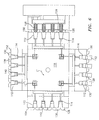
- a second rotation of a further 90 degrees as shown in Figure 4 allows the operation to continue as a third set of mold cavities are filled (not shown).
- slides 28, 30 continue to be in the closed position.
- mold cavity 12 with cooled part 42 therein is facing downwards and slides 28, 30 are moved aside by their cylinders (not shown) in the direction of arrows E.
- a further set of articles may then be molded as before.
- the piston 14 is now advanced its full stroke in the direction of arrow F to push part 42 out of mold cavity 12 as shown in Figure 5.
- the slides 28, 30 are repositioned to the position shown in Figures 1-4 and turret block 18 rotates a final 90 degrees in the direction of arrow C to begin the cycle again.
- Figure 6 shows a representative process and apparatus of the present invention with a multi-cavity block with each face showing four mold cavities and with four faces.
- each face could have a plurality of rows of mold cavities, as for example, a 4 X 4 array with therefore 16 mold cavities on each face.
- turret block 118 includes four faces 150, 152, 154 and 156.
- Each face includes four mold cavities 112 with each mold cavity including a piston 114 and with slides 128, 130 associated with each mold cavity.
- Conventional valve gated hot runner nozzles 126 feed plastic resin into the mold cavities on mold face 150 as shown in Figure 6 while the previously injected molded parts 142 in the mold cavities on mold faces 152 and 154 continue to cool and more bubbles form therein as shown in Figures 3 and 4, and with mold block 118 rotating in the direction of arrow C'. Molded parts 142 in the mold cavities on mold face 156 are then ejected as in Figure 5. Otherwise the operation is similar to that shown in Figures 1-5. Naturally, a different number of mold faces and a different number of cavities may be used, if desired.
- the present invention represents an efficient and expeditious operation.
- the time consuming cooling and gas bubble forming part of the cycle is performed outside of the mold filling station, permitting a much more efficient use of equipment and energy and at the same time additional articles are formed permitting a high volume operation.
- other articles in addition to wine corks may be molded in accordance with the present invention.
Abstract
Description
- Application Serial No. 60/069,640 for PROCESS AND APPARATUS FOR MOLDING PLASTIC ARTICLES, filed December 15, 1997.
- The present invention relates to a method and apparatus for making plastic articles, especially wine corks, from plastic resin in a continuous and efficient operation.
- Articles such as wine corks as well as others are made using a plastic resin which contains a blowing agent such that after injection of the resin into a mold cavity gas bubbles are formed in the plastic resin. The plastic resin expands in volume as the mold cavity volume is allowed to expand.
- Plastic wine corks are particularly useful as they represent an alternative to cork for sealing wine bottles. These and other articles may be prepared by the process described above which is termed "foam molding". This process and apparatus requires that the mold cavity can expand to allow gas bubbles to form in the resin as it cools.
- Unfortunately, however, this procedure takes a substantial amount of time as cooling a relatively thick part, particularly a relatively thick part that contains gas bubbles therein, is inherently slow especially due to the very poor thermal transmission properties of the gas filled plastic.
- The main object of the present invention is to provide an efficient and expeditious process and apparatus for preparing relatively thick plastic parts containing gas therein.
- Another object of the present invention is to provide a process and apparatus as aforesaid for efficiently and expeditiously preparing such relatively thick plastic parts, as plastic wine corks.
- A further object of the present invention is to provide a process and apparatus as aforesaid that separates the cooling phase of the molding cycle from the remainder of the cycle allowing the operation to be more effectively performed.
- The present invention performs the molding operation in a first state of the cycle. Subsequent stages permit mold cavity expansion, article cooling and article expansion while at the same time permitting the molding of further articles. The final stage of the cycle is the ejection of the cooled and expanded article.
- Thus, the present invention efficiently permits the continuous formation of additional articles while the initially formed article or articles continue their processing steps, as by cooling, expansion and ejection.
- Thus, the present invention comprises a process for preparing a molded article, as for example wine corks, which comprises: filling a first mold cavity via a feeding unit in engagement with said first mold cavity with plastic containing a volume expanding agent; moving the filled first mold cavity and feeding unit away from each other, moving a second mold cavity and said feeding unit into engagement with each other and filling said second mold cavity via said feeding unit with plastic containing a volume expanding agent; expanding said plastic in said first mold cavity via said volume expanding agent while said second mold cavity is in engagement with said feeding unit; and ejecting the expanded article from the first mold cavity.
- The present invention also comprises an apparatus for forming a molded article, which comprises: first and second mold cavities spaced from each other for forming molded articles; a feeding unit for separately feeding plastic containing a volume expanding agent into said first and second mold cavities; means for separately moving said first and second mold cavities and said feeding unit into and out of engagement with each other; wherein said plastic is expanded in said first mold cavity via said volume expanding agent while said second mold cavity is in engagement with said feeding unit; and means for ejecting the expanded article from the first mold cavity.
- Further features of the present invention will appear hereinbelow.
- The present invention will be more readily understood from a consideration of the accompanying drawings, wherein:
- Figure 1 is a partly schematic, sectional view of the present invention in a mold closed position and during injection;
- Figure 2 is a partly schematic sectional view of a further stage of the present invention in a mold open position with the mold closing slides in the closed position;
- Figure 3 is a partly schematic, sectional view of a further stage of the present invention after a first 90 degree rotation of the mold;
- Figure 4 is a partly schematic, sectional view of a still further stage of the present invention after a second 90 degree rotation of the mold;
- Figure 5 is a partly schematic, sectional view of a still further stage of the present invention after a third 90 degree rotation of the mold and with ejection of the final part; and
- Figure 6 is a partly schematic, sectional view of the present invention showing a multi-cavity block with each face having four cavities.
-
- The process and apparatus of the present invention preferably uses a machine and process where the mold indexes to different positions, such as shown in copending U.S. Patent Application Serial No. 08/611,362, the disclosure of which is incorporated herein by reference.
- Referring to Figure 1 herein,
mold block 10 contains amold cavity 12 therein. Piston 14 slides inmold cavity 12.Mold block 10 is mounted viaspacers 16 tomachine turret block 18 which in turn is mounted on a slidable carriage (not shown) which moves towards and away fromstationary platen 20 of the injection molding machine. Mounted to thestationary platen 20 ishot runner block 22 which in turn containshot runner manifold 24 and conventional valve gatedhot runner nozzle 26 for conveying the heated plastic resin to themold cavity 12. - Mold
closing slides mold cavity 12 and are moved aside to permit access tomold cavity 12 by the closing movement ofturret block 18 towardshot runner block 22. Theangled faces 32 onslides nozzle tip body 34 and move transversely to the closing motion thereby permitting nozzle access to themold cavity 12. Cylinders (not shown) may be mounted tomold block 10 to act againstslides nozzle 26. A clamp force which is generated by known means (not shown) keeps themold block 10 pressed againsthot runner block 22 during injection of the plastic resin into themold cavity 12. The plastic resin is then injected intomold cavity 12 to fill the cavity. As indicated hereinabove, the plastic resin contains a blowing agent in accordance with known practice. - As shown in Figure 2, after the
mold cavity 12 is filled with plastic resin, theturret block 18 moves away fromstationary platen 20 by cylinders (not shown) in the direction of arrow A, thereby causingslides mold cavity 12 in the direction of arrows B, urged by the slide cylinders (not shown). Simultaneously,piston 14 begins to retract inmold cavity 12 causing the volume ofmold cavity 12 to increase. Piston 14 is moved viarod 36 which is connected toplate 38 which in turn is moved bycylinder 40 mounted withinturret block 18. Naturally, other means may be used to movepiston 14 or to expand the volume ofmold cavity 12. As the mold cavity volume increases the pressure acting on the plastic resin in the mold cavity is reduced which allows gas bubbles to form in the plastic resin. - After
turret block 18 has moved away fromstationary platen 20 to provide clearance for rotation of the turret block, the block rotates 90 degrees in the direction of arrow C onrod 41 as shown in Figure 3 to present a new face of mold cavities to be filled in a known fashion (not shown). Naturally, the 90 degree rotation is exemplificative only and other degrees of rotation may be used. In the new position shown in Figure 3, the filledmold cavity 12 continues to expand aspiston 14 is retracted all the way to the end of the mold cavity in the direction of arrow D. Retraction to the end of the mold cavity may of course take place in a different stage of the operation. Themolded part 42 continues to cool and more gas bubbles form therein. - A second rotation of a further 90 degrees as shown in Figure 4 allows the operation to continue as a third set of mold cavities are filled (not shown). In the Figure 3 and Figure 4 position,
slides - After a third rotation of a further 90 degrees as shown in Figure 5,
mold cavity 12 with cooledpart 42 therein is facing downwards andslides piston 14 is now advanced its full stroke in the direction of arrow F to pushpart 42 out ofmold cavity 12 as shown in Figure 5. Thereafter, theslides turret block 18 rotates a final 90 degrees in the direction of arrow C to begin the cycle again. - Figure 6 shows a representative process and apparatus of the present invention with a multi-cavity block with each face showing four mold cavities and with four faces. In fact, if desired, each face could have a plurality of rows of mold cavities, as for example, a 4 X 4 array with therefore 16 mold cavities on each face.
- Thus, referring to Figure 6,
turret block 118 includes fourfaces mold cavities 112 with each mold cavity including apiston 114 and withslides hot runner nozzles 126 feed plastic resin into the mold cavities onmold face 150 as shown in Figure 6 while the previously injectedmolded parts 142 in the mold cavities onmold faces mold block 118 rotating in the direction of arrow C'. Moldedparts 142 in the mold cavities onmold face 156 are then ejected as in Figure 5. Otherwise the operation is similar to that shown in Figures 1-5. Naturally, a different number of mold faces and a different number of cavities may be used, if desired. - It is apparent that the present invention represents an efficient and expeditious operation. The time consuming cooling and gas bubble forming part of the cycle is performed outside of the mold filling station, permitting a much more efficient use of equipment and energy and at the same time additional articles are formed permitting a high volume operation. Naturally, other articles in addition to wine corks may be molded in accordance with the present invention.
- It is to be understood that the invention is not limited to the illustrations described and shown herein, which are deemed to be merely illustrative of the best modes of carrying out the invention, and which are susceptible of modification of form, size, arrangement of parts and details of operation. The invention rather is intended to encompass all such modifications which are within its spirit and scope as defined by the claims.
Claims (21)
- A process for preparing a molded article (42, 142), which comprises:filling a first mold cavity (12, 112) via a feeding unit in engagement with said first mold cavity (12, 112) with plastic containing a volume expanding agent;moving the filled first mold cavity (12, 112) and feeding unit away from each other, moving a second mold cavity and said feeding unit into engagement with each other and filling said second mold cavity via said feeding unit with plastic containing a volume expanding agent;expanding said plastic in said first mold cavity (12, 112) via said volume expanding agent while said second mold cavity is in engagement with said feeding unit; andejecting the expanded article (42, 142) from the first mold cavity (12, 112).
- A process according to claim 1, including carrying said first and second mold cavities on a holding means (18, 118), and moving said first and second mold cavities by moving said holding means (18, 118).
- A process according to claim 1, including a plurality of said mold cavities (112) spaced from each other, and separately filling each mold cavity (112) while the other mold cavities (112) are spaced from the mold cavity (112) being filled.
- A process according to claim 1, including at least in part moving said mold cavities (12, 112) in a rotary manner.
- A process according to claim 3, including the step of expanding said plastic in said second mold cavity (12, 112) via said volume expanding agent while a separate mold cavity is in engagement with said feeding unit, and ejecting the expanded article from said second mold cavity.
- A process according to claim 2, including carrying said mold cavities (12, 112) on a mold block (18, 118).
- A process according to claim 1, including expanding the mold cavities to provide space therein for expansion of said plastic.
- A process according to claim 1, including mold cavity orifices for engagement with said feeding unit, and including the step of closing said mold orifices after said mold cavities ( 12, 112) have been filled.
- A process according to claim 8, including mold closing slides (28, 30; 128, 130) for closing said mold orifices, including the step of opening said mold closing slides (28, 30; 128, 130) to permit ejection of expanded articles (42, 142) from mold cavities (12, 112).
- A process according to claim 7, wherein said mold cavities (12, 112) are expanded by expanding elements (14, 114) which are also operative to eject the expanded parts.
- A process according to claim 1, including greater than two mold cavities (112), wherein one of which is in engagement with said filling unit while plastic is expanded in at least some of the other of said mold cavities.
- Apparatus for forming a molded article (42, 142), which comprises:first and second mold cavities (12, 112) spaced from each other for forming molded articles (42, 142);a feeding unit for separately feeding plastic containing a volume expanding agent into said first and second mold cavities (12, 112);means for separately moving said first and second mold cavities and said feeding unit into and out of engagement with each other;wherein said plastic is expanded in said first mold cavity (12, 112) via said volume expanding agent while said second mold cavity is in engagement with said feeding unit; andmeans (14, 114) for ejecting the expanded article from the first mold cavity (12, 112).
- Apparatus according to claim 12, including a holding means (18, 118) for carrying said first and second mold cavities (12, 112) operative to move said first and second mold cavities.
- Apparatus according to claim 12, including a plurality of said mold cavities (122) spaced from each other, wherein said feeding unit separately feeds said plastic into each mold cavity (112) while the plastic is expanded in at least some of the other mold cavities.
- Apparatus according to claim 12, wherein said means (18, 118) for moving at least in part moves said mold cavities (12, 112) in a rotary manner.
- Apparatus according to claim 14, wherein said plastic is expanded in said second mold cavity via said volume expanding agent while a separate one of said mold cavities is in engagement with said feeding unit, and means (14, 114) for ejecting the expanded article from said second mold cavity.
- Apparatus according to claim 13, including a mold block (18, 118) for carrying said mold cavities (12, 112).
- Apparatus according to claim 12, including means (14, 114) in the mold cavities (12, 112) for expanding the mold cavities (12, 112) to provide space therein for expansion of said plastic.
- Apparatus according to claim 12, including mold orifices for engagement with said feeding unit, and means (28, 30; 128, 130) to close said mold orifices after said mold cavities (12, 112) have been filled.
- Apparatus according to claim 19, including mold closing slides (28, 30; 128, 130) for closing the mold orifices, wherein said mold closing slides are operative to open to permit ejection of expanded articles (42, 142) from the mold cavities (12, 112).
- Apparatus according to claim 18, wherein said means (14, 114) for expanding said mold cavities (12, 112) are expanding elements which are also operative to eject the molded parts (42, 142).
Applications Claiming Priority (4)
| Application Number | Priority Date | Filing Date | Title |
|---|---|---|---|
| US6964097P | 1997-12-15 | 1997-12-15 | |
| US69640P | 1997-12-15 | ||
| US203457 | 1998-12-02 | ||
| US09/203,457 US6099769A (en) | 1997-12-15 | 1998-12-02 | Process for molding plastic articles |
Publications (2)
| Publication Number | Publication Date |
|---|---|
| EP0924042A1 true EP0924042A1 (en) | 1999-06-23 |
| EP0924042B1 EP0924042B1 (en) | 2003-07-09 |
Family
ID=26750274
Family Applications (1)
| Application Number | Title | Priority Date | Filing Date |
|---|---|---|---|
| EP98123750A Expired - Lifetime EP0924042B1 (en) | 1997-12-15 | 1998-12-14 | Process and apparatus for molding plastic articles |
Country Status (6)
| Country | Link |
|---|---|
| US (2) | US6099769A (en) |
| EP (1) | EP0924042B1 (en) |
| JP (1) | JP3066745B2 (en) |
| AT (1) | ATE244629T1 (en) |
| AU (1) | AU706446B1 (en) |
| DE (1) | DE69816252T2 (en) |
Cited By (1)
| Publication number | Priority date | Publication date | Assignee | Title |
|---|---|---|---|---|
| WO2000047390A1 (en) * | 1999-02-11 | 2000-08-17 | C.T.E.B. Equipment Pty. Ltd. | Improvements in moulded synthetic closure manufacture |
Families Citing this family (9)
| Publication number | Priority date | Publication date | Assignee | Title |
|---|---|---|---|---|
| ES2290049T3 (en) * | 1999-08-30 | 2008-02-16 | Sekisui Chemical Co., Ltd. | PRODUCTION METHOD FOR THERMOPLASTIC RESIN FOAM AND MOLDING MOLD FOR THE SAME. |
| DE10022192A1 (en) * | 2000-05-03 | 2001-11-15 | Mannesmann Ag | Device for removing injection molded parts |
| EP1372930A1 (en) * | 2001-02-26 | 2004-01-02 | Jes Tougaard Gram | Ejectorsystem |
| DE10319025A1 (en) * | 2003-04-28 | 2004-11-18 | Mht Mold & Hotrunner Technology Ag | Cork tool and process for the production thereof |
| US7559756B2 (en) * | 2004-06-30 | 2009-07-14 | Husky Injection Molding Systems, Ltd. | Apparatus and method for actuation of injection molding shooting pots |
| US20080029932A1 (en) * | 2006-08-02 | 2008-02-07 | Shape Corporation | Molding machine with platen-attached hot runner manifold |
| DE102007060863B4 (en) | 2007-12-18 | 2014-10-02 | Kraussmaffei Technologies Gmbh | Process for the production of multi-component plastic corks |
| US8087925B2 (en) * | 2009-03-06 | 2012-01-03 | Tachi-S Co., Ltd. | Device for forming headrest |
| US20140212610A1 (en) * | 2011-09-01 | 2014-07-31 | Canon Kabushiki Kaisha | Foam-molding parts manufacturing method, foam-molding part, and foam-mold |
Citations (3)
| Publication number | Priority date | Publication date | Assignee | Title |
|---|---|---|---|---|
| EP0056213A1 (en) * | 1980-12-23 | 1982-07-21 | Societe Nouvelle De Bouchons Plastiques S.N.B.P. | Plug made of foam plastics material |
| US4783292A (en) * | 1987-06-15 | 1988-11-08 | Rogers Roy K | Method of injection molding a foamed plastic article using a relatively light gas as a blowing agent |
| DE4004774A1 (en) * | 1989-02-15 | 1990-08-16 | Dunlop Ltd | MOLDING DEVICE |
Family Cites Families (21)
| Publication number | Priority date | Publication date | Assignee | Title |
|---|---|---|---|---|
| US3541645A (en) * | 1967-10-30 | 1970-11-24 | Albert Lowell Bunting | Automatic rotary plastic molding machine |
| US3771928A (en) * | 1971-06-28 | 1973-11-13 | T Gostyn | Apparatus for molding polyurethane articles |
| US3941539A (en) * | 1972-12-05 | 1976-03-02 | Continental Can Company, Inc. | Injection blow molding apparatus and method |
| US3881855A (en) * | 1973-01-16 | 1975-05-06 | Francis Farkas | Injection blow molding apparatus |
| DE2929165C2 (en) * | 1979-07-19 | 1981-12-24 | Röhm GmbH, 6100 Darmstadt | Process for the production of a foam board |
| IT1136543B (en) * | 1980-09-04 | 1986-08-27 | Enoplastic Spa | PROCESS AND MEANS OF MANUFACTURING PLASTIC PLUGS FOR SPARKLING BOTTLES WHICH CONTAIN FUNCTIONS OF CAP, CAGE AND SEAL, APPLICABLE WITH AUTOMATIC PROCESS AND PARTICULARLY PLUGS IN ONE PIECE OBTAINED BY SUCH PROCESS AND PROCESSING AND AUTOMATION PROCESS CAPPING, CRABING AND SEALING |
| US4389358A (en) * | 1981-06-22 | 1983-06-21 | Kmmco Structural Foam, Inc. | Method and apparatus for making an integral structural cellular and non-cellular plastic or resinous article with a smooth outer surface |
| CA1174814A (en) * | 1982-05-05 | 1984-09-25 | Ladislav Hujik | Mold for footwear sole |
| SE448967B (en) * | 1983-03-10 | 1987-03-30 | Petainer Sa | SET AND DEVICE FOR MANUFACTURING THERMOPLASTIC CONTAINERS |
| DE3516175A1 (en) * | 1985-05-06 | 1986-11-06 | Fa. Martin Rudolph, 5620 Velbert | LENGTH ADJUSTABLE BLOW MOLD |
| DE3643821A1 (en) * | 1986-11-05 | 1988-05-19 | Kloeckner Ferromatik Desma | MOLDING STATIONS, ESPECIALLY FOR ROUND TABLE SYSTEMS, FOR MOLDING ON THE SHOE SOLE WITH AN ELASTOMER OUTSOLE AND A MIDSOLE MADE OF A MIXTURE OF ISOCYANATE AND POLYOL ON SHOE SHOES TO POLYURETHANE |
| US5160752A (en) * | 1988-12-28 | 1992-11-03 | Sony Corporation | Mold for forming a tape cassette reel |
| JPH0777739B2 (en) * | 1990-10-05 | 1995-08-23 | 住友化学工業株式会社 | Method for molding polypropylene resin foam molding |
| US5082609A (en) * | 1990-10-22 | 1992-01-21 | Bridgestone Australia Ltd. | Method of forming a moulded panel |
| US5246976A (en) * | 1991-04-23 | 1993-09-21 | Astro-Valcour, Inc. | Apparatus for producing foamed, molded thermoplastic articles and articles produced thereby |
| IT1247883B (en) * | 1991-05-03 | 1995-01-05 | Devi Spa | PROCEDURE AND MACHINE FOR THE MOLDING OF COUPLED PLASTIC MATERIAL |
| DE4306447C2 (en) * | 1992-03-30 | 1996-11-28 | Hecker & Krosch Gmbh & Co Kg | Recycling process for rigid polyurethane foam |
| US5403645A (en) * | 1993-04-01 | 1995-04-04 | General Motors Corporation | Molded-in cloth insert door trim |
| FR2714631B1 (en) * | 1993-12-30 | 1996-03-01 | Sidel Sa | Method and installation for the manufacture of containers, in particular bottles, of thermoplastic material. |
| US5547621A (en) * | 1994-09-30 | 1996-08-20 | Taisei Plas Co., Ltd. | Cavity expanding and contracting foam injection molding method |
| CA2160644C (en) * | 1995-10-16 | 2005-05-24 | Jobst Ulrich Gellert | Cooled thread split inserts for injection molding preforms |
-
1998
- 1998-12-02 US US09/203,457 patent/US6099769A/en not_active Expired - Fee Related
- 1998-12-11 AU AU97066/98A patent/AU706446B1/en not_active Ceased
- 1998-12-14 DE DE69816252T patent/DE69816252T2/en not_active Expired - Fee Related
- 1998-12-14 EP EP98123750A patent/EP0924042B1/en not_active Expired - Lifetime
- 1998-12-14 AT AT98123750T patent/ATE244629T1/en not_active IP Right Cessation
- 1998-12-15 JP JP10356696A patent/JP3066745B2/en not_active Expired - Fee Related
-
2000
- 2000-05-16 US US09/572,685 patent/US6290486B1/en not_active Expired - Fee Related
Patent Citations (4)
| Publication number | Priority date | Publication date | Assignee | Title |
|---|---|---|---|---|
| EP0056213A1 (en) * | 1980-12-23 | 1982-07-21 | Societe Nouvelle De Bouchons Plastiques S.N.B.P. | Plug made of foam plastics material |
| US4413744A (en) * | 1980-12-23 | 1983-11-08 | Societe Nouvelle De Bouchons Plastiques S.N.B.P. | Expanded plastic bottle stopper |
| US4783292A (en) * | 1987-06-15 | 1988-11-08 | Rogers Roy K | Method of injection molding a foamed plastic article using a relatively light gas as a blowing agent |
| DE4004774A1 (en) * | 1989-02-15 | 1990-08-16 | Dunlop Ltd | MOLDING DEVICE |
Cited By (3)
| Publication number | Priority date | Publication date | Assignee | Title |
|---|---|---|---|---|
| WO2000047390A1 (en) * | 1999-02-11 | 2000-08-17 | C.T.E.B. Equipment Pty. Ltd. | Improvements in moulded synthetic closure manufacture |
| EP1159118A1 (en) * | 1999-02-11 | 2001-12-05 | C.T.E.B. Equipment PTY. Ltd. | Improvements in moulded synthetic closure manufacture |
| EP1159118A4 (en) * | 1999-02-11 | 2002-06-05 | C T E B Equipment Pty Ltd | Improvements in moulded synthetic closure manufacture |
Also Published As
| Publication number | Publication date |
|---|---|
| AU706446B1 (en) | 1999-06-17 |
| JPH11235736A (en) | 1999-08-31 |
| ATE244629T1 (en) | 2003-07-15 |
| DE69816252T2 (en) | 2004-05-27 |
| US6099769A (en) | 2000-08-08 |
| EP0924042B1 (en) | 2003-07-09 |
| DE69816252D1 (en) | 2003-08-14 |
| JP3066745B2 (en) | 2000-07-17 |
| US6290486B1 (en) | 2001-09-18 |
Similar Documents
| Publication | Publication Date | Title |
|---|---|---|
| US4786455A (en) | Rotary injection turret and method of utilizing the same in the making of preforms | |
| EP0001626B1 (en) | Injection blow molding apparatus method | |
| KR100553165B1 (en) | A the mold apparatus, and a molding machine having the mold apparatus | |
| US4205950A (en) | Injection molding apparatus | |
| US7597834B2 (en) | Rotary molding machine | |
| US4449913A (en) | Rotary injection turret for the making of preforms | |
| CA2482781C (en) | Method and apparatus for post mold cooling of plastic pieces | |
| US4243620A (en) | Method of manufacturing an object in plastics material and object obtained thereby | |
| US4092385A (en) | Method of producing molded parts with a smooth noncellular skin and a cellular core from foamable thermoplastic material | |
| US4422995A (en) | Method and apparatus for molding hollow, slender workpieces | |
| US6099769A (en) | Process for molding plastic articles | |
| US6358446B1 (en) | Method of injection moulding a foamed article | |
| US20010038163A1 (en) | Shuttle system for an apparatus and method for injection molding | |
| CA1171215A (en) | Fluid-assisted core-release method and apparatus | |
| US4077760A (en) | Injection molding process and apparatus | |
| US5501589A (en) | Injection blow molding apparatus | |
| US4150088A (en) | Method of injection molding with displacement of mold from injection position and applying pressure during cooling | |
| EP0035916B1 (en) | Conversion apparatus for injection moulding machines | |
| CN101945747B (en) | Compression injection moulding method and device for preforms | |
| KR20210143114A (en) | Injection method and injection apparatus for molten resin, and injection stretch blow molding machine using injection apparatus | |
| US3807923A (en) | Injection/blow-moulding apparatus | |
| CA1148709A (en) | Method and apparatus for injection blow molding an article with improved detail definition | |
| JPH0994844A (en) | Method and apparatus for making hollow molding | |
| JPS62140819A (en) | Mold for hollow molding |
Legal Events
| Date | Code | Title | Description |
|---|---|---|---|
| PUAI | Public reference made under article 153(3) epc to a published international application that has entered the european phase |
Free format text: ORIGINAL CODE: 0009012 |
|
| AK | Designated contracting states |
Kind code of ref document: A1 Designated state(s): AT CH DE FR IT LI NL |
|
| AX | Request for extension of the european patent |
Free format text: AL;LT;LV;MK;RO;SI |
|
| 17P | Request for examination filed |
Effective date: 19990924 |
|
| AKX | Designation fees paid |
Free format text: AT CH DE FR IT LI NL |
|
| 17Q | First examination report despatched |
Effective date: 20000217 |
|
| GRAH | Despatch of communication of intention to grant a patent |
Free format text: ORIGINAL CODE: EPIDOS IGRA |
|
| GRAH | Despatch of communication of intention to grant a patent |
Free format text: ORIGINAL CODE: EPIDOS IGRA |
|
| GRAA | (expected) grant |
Free format text: ORIGINAL CODE: 0009210 |
|
| AK | Designated contracting states |
Designated state(s): AT CH DE FR IT LI NL |
|
| REG | Reference to a national code |
Ref country code: CH Ref legal event code: EP |
|
| REF | Corresponds to: |
Ref document number: 69816252 Country of ref document: DE Date of ref document: 20030814 Kind code of ref document: P |
|
| REG | Reference to a national code |
Ref country code: CH Ref legal event code: NV Representative=s name: BOVARD AG PATENTANWAELTE |
|
| PLBE | No opposition filed within time limit |
Free format text: ORIGINAL CODE: 0009261 |
|
| STAA | Information on the status of an ep patent application or granted ep patent |
Free format text: STATUS: NO OPPOSITION FILED WITHIN TIME LIMIT |
|
| ET | Fr: translation filed | ||
| 26N | No opposition filed |
Effective date: 20040414 |
|
| PGFP | Annual fee paid to national office [announced via postgrant information from national office to epo] |
Ref country code: NL Payment date: 20041205 Year of fee payment: 7 |
|
| PGFP | Annual fee paid to national office [announced via postgrant information from national office to epo] |
Ref country code: FR Payment date: 20041208 Year of fee payment: 7 |
|
| PGFP | Annual fee paid to national office [announced via postgrant information from national office to epo] |
Ref country code: DE Payment date: 20041209 Year of fee payment: 7 |
|
| PGFP | Annual fee paid to national office [announced via postgrant information from national office to epo] |
Ref country code: AT Payment date: 20041213 Year of fee payment: 7 |
|
| PGFP | Annual fee paid to national office [announced via postgrant information from national office to epo] |
Ref country code: CH Payment date: 20041215 Year of fee payment: 7 |
|
| PG25 | Lapsed in a contracting state [announced via postgrant information from national office to epo] |
Ref country code: IT Free format text: LAPSE BECAUSE OF NON-PAYMENT OF DUE FEES;WARNING: LAPSES OF ITALIAN PATENTS WITH EFFECTIVE DATE BEFORE 2007 MAY HAVE OCCURRED AT ANY TIME BEFORE 2007. THE CORRECT EFFECTIVE DATE MAY BE DIFFERENT FROM THE ONE RECORDED. Effective date: 20051214 Ref country code: AT Free format text: LAPSE BECAUSE OF NON-PAYMENT OF DUE FEES Effective date: 20051214 |
|
| PG25 | Lapsed in a contracting state [announced via postgrant information from national office to epo] |
Ref country code: LI Free format text: LAPSE BECAUSE OF NON-PAYMENT OF DUE FEES Effective date: 20051231 Ref country code: CH Free format text: LAPSE BECAUSE OF NON-PAYMENT OF DUE FEES Effective date: 20051231 |
|
| PG25 | Lapsed in a contracting state [announced via postgrant information from national office to epo] |
Ref country code: NL Free format text: LAPSE BECAUSE OF NON-PAYMENT OF DUE FEES Effective date: 20060701 Ref country code: DE Free format text: LAPSE BECAUSE OF NON-PAYMENT OF DUE FEES Effective date: 20060701 |
|
| REG | Reference to a national code |
Ref country code: CH Ref legal event code: PL |
|
| PG25 | Lapsed in a contracting state [announced via postgrant information from national office to epo] |
Ref country code: FR Free format text: LAPSE BECAUSE OF NON-PAYMENT OF DUE FEES Effective date: 20060831 |
|
| NLV4 | Nl: lapsed or anulled due to non-payment of the annual fee |
Effective date: 20060701 |
|
| REG | Reference to a national code |
Ref country code: FR Ref legal event code: ST Effective date: 20060831 |