EP0921738B1 - Method and equipment for rapid manufacture of loop material - Google Patents
Method and equipment for rapid manufacture of loop material Download PDFInfo
- Publication number
- EP0921738B1 EP0921738B1 EP97934972A EP97934972A EP0921738B1 EP 0921738 B1 EP0921738 B1 EP 0921738B1 EP 97934972 A EP97934972 A EP 97934972A EP 97934972 A EP97934972 A EP 97934972A EP 0921738 B1 EP0921738 B1 EP 0921738B1
- Authority
- EP
- European Patent Office
- Prior art keywords
- sheet
- fibers
- forming
- portions
- forming member
- Prior art date
- Legal status (The legal status is an assumption and is not a legal conclusion. Google has not performed a legal analysis and makes no representation as to the accuracy of the status listed.)
- Expired - Lifetime
Links
Images


Classifications
-
- D—TEXTILES; PAPER
- D04—BRAIDING; LACE-MAKING; KNITTING; TRIMMINGS; NON-WOVEN FABRICS
- D04H—MAKING TEXTILE FABRICS, e.g. FROM FIBRES OR FILAMENTARY MATERIAL; FABRICS MADE BY SUCH PROCESSES OR APPARATUS, e.g. FELTS, NON-WOVEN FABRICS; COTTON-WOOL; WADDING ; NON-WOVEN FABRICS FROM STAPLE FIBRES, FILAMENTS OR YARNS, BONDED WITH AT LEAST ONE WEB-LIKE MATERIAL DURING THEIR CONSOLIDATION
- D04H13/00—Other non-woven fabrics
- D04H13/001—Making non-woven fabrics from staple fibres, filaments or yarns, bonded to at least one web-like material, e.g. woven, knitted non-woven fabric, paper, leather, during consolidation
- D04H13/007—Making non-woven fabrics from staple fibres, filaments or yarns, bonded to at least one web-like material, e.g. woven, knitted non-woven fabric, paper, leather, during consolidation strengthened or consolidated by welding together the various components
-
- C—CHEMISTRY; METALLURGY
- C08—ORGANIC MACROMOLECULAR COMPOUNDS; THEIR PREPARATION OR CHEMICAL WORKING-UP; COMPOSITIONS BASED THEREON
- C08J—WORKING-UP; GENERAL PROCESSES OF COMPOUNDING; AFTER-TREATMENT NOT COVERED BY SUBCLASSES C08B, C08C, C08F, C08G or C08H
- C08J5/00—Manufacture of articles or shaped materials containing macromolecular substances
- C08J5/18—Manufacture of films or sheets
-
- A—HUMAN NECESSITIES
- A44—HABERDASHERY; JEWELLERY
- A44B—BUTTONS, PINS, BUCKLES, SLIDE FASTENERS, OR THE LIKE
- A44B18/00—Fasteners of the touch-and-close type; Making such fasteners
- A44B18/0003—Fastener constructions
- A44B18/0011—Female or loop elements
-
- B—PERFORMING OPERATIONS; TRANSPORTING
- B32—LAYERED PRODUCTS
- B32B—LAYERED PRODUCTS, i.e. PRODUCTS BUILT-UP OF STRATA OF FLAT OR NON-FLAT, e.g. CELLULAR OR HONEYCOMB, FORM
- B32B27/00—Layered products comprising a layer of synthetic resin
- B32B27/12—Layered products comprising a layer of synthetic resin next to a fibrous or filamentary layer
-
- B—PERFORMING OPERATIONS; TRANSPORTING
- B32—LAYERED PRODUCTS
- B32B—LAYERED PRODUCTS, i.e. PRODUCTS BUILT-UP OF STRATA OF FLAT OR NON-FLAT, e.g. CELLULAR OR HONEYCOMB, FORM
- B32B3/00—Layered products comprising a layer with external or internal discontinuities or unevennesses, or a layer of non-planar form; Layered products having particular features of form
- B32B3/26—Layered products comprising a layer with external or internal discontinuities or unevennesses, or a layer of non-planar form; Layered products having particular features of form characterised by a particular shape of the outline of the cross-section of a continuous layer; characterised by a layer with cavities or internal voids ; characterised by an apertured layer
- B32B3/28—Layered products comprising a layer with external or internal discontinuities or unevennesses, or a layer of non-planar form; Layered products having particular features of form characterised by a particular shape of the outline of the cross-section of a continuous layer; characterised by a layer with cavities or internal voids ; characterised by an apertured layer characterised by a layer comprising a deformed thin sheet, i.e. the layer having its entire thickness deformed out of the plane, e.g. corrugated, crumpled
-
- B—PERFORMING OPERATIONS; TRANSPORTING
- B32—LAYERED PRODUCTS
- B32B—LAYERED PRODUCTS, i.e. PRODUCTS BUILT-UP OF STRATA OF FLAT OR NON-FLAT, e.g. CELLULAR OR HONEYCOMB, FORM
- B32B38/00—Ancillary operations in connection with laminating processes
- B32B38/0012—Mechanical treatment, e.g. roughening, deforming, stretching
-
- B—PERFORMING OPERATIONS; TRANSPORTING
- B32—LAYERED PRODUCTS
- B32B—LAYERED PRODUCTS, i.e. PRODUCTS BUILT-UP OF STRATA OF FLAT OR NON-FLAT, e.g. CELLULAR OR HONEYCOMB, FORM
- B32B5/00—Layered products characterised by the non- homogeneity or physical structure, i.e. comprising a fibrous, filamentary, particulate or foam layer; Layered products characterised by having a layer differing constitutionally or physically in different parts
- B32B5/02—Layered products characterised by the non- homogeneity or physical structure, i.e. comprising a fibrous, filamentary, particulate or foam layer; Layered products characterised by having a layer differing constitutionally or physically in different parts characterised by structural features of a fibrous or filamentary layer
- B32B5/04—Layered products characterised by the non- homogeneity or physical structure, i.e. comprising a fibrous, filamentary, particulate or foam layer; Layered products characterised by having a layer differing constitutionally or physically in different parts characterised by structural features of a fibrous or filamentary layer characterised by a layer being specifically extensible by reason of its structure or arrangement, e.g. by reason of the chemical nature of the fibres or filaments
-
- D—TEXTILES; PAPER
- D04—BRAIDING; LACE-MAKING; KNITTING; TRIMMINGS; NON-WOVEN FABRICS
- D04H—MAKING TEXTILE FABRICS, e.g. FROM FIBRES OR FILAMENTARY MATERIAL; FABRICS MADE BY SUCH PROCESSES OR APPARATUS, e.g. FELTS, NON-WOVEN FABRICS; COTTON-WOOL; WADDING ; NON-WOVEN FABRICS FROM STAPLE FIBRES, FILAMENTS OR YARNS, BONDED WITH AT LEAST ONE WEB-LIKE MATERIAL DURING THEIR CONSOLIDATION
- D04H11/00—Non-woven pile fabrics
- D04H11/08—Non-woven pile fabrics formed by creation of a pile on at least one surface of a non-woven fabric without addition of pile-forming material, e.g. by needling, by differential shrinking
-
- B—PERFORMING OPERATIONS; TRANSPORTING
- B32—LAYERED PRODUCTS
- B32B—LAYERED PRODUCTS, i.e. PRODUCTS BUILT-UP OF STRATA OF FLAT OR NON-FLAT, e.g. CELLULAR OR HONEYCOMB, FORM
- B32B2307/00—Properties of the layers or laminate
- B32B2307/70—Other properties
- B32B2307/726—Permeability to liquids, absorption
- B32B2307/7265—Non-permeable
-
- B—PERFORMING OPERATIONS; TRANSPORTING
- B32—LAYERED PRODUCTS
- B32B—LAYERED PRODUCTS, i.e. PRODUCTS BUILT-UP OF STRATA OF FLAT OR NON-FLAT, e.g. CELLULAR OR HONEYCOMB, FORM
- B32B2555/00—Personal care
- B32B2555/02—Diapers or napkins
-
- Y—GENERAL TAGGING OF NEW TECHNOLOGICAL DEVELOPMENTS; GENERAL TAGGING OF CROSS-SECTIONAL TECHNOLOGIES SPANNING OVER SEVERAL SECTIONS OF THE IPC; TECHNICAL SUBJECTS COVERED BY FORMER USPC CROSS-REFERENCE ART COLLECTIONS [XRACs] AND DIGESTS
- Y10—TECHNICAL SUBJECTS COVERED BY FORMER USPC
- Y10T—TECHNICAL SUBJECTS COVERED BY FORMER US CLASSIFICATION
- Y10T156/00—Adhesive bonding and miscellaneous chemical manufacture
- Y10T156/10—Methods of surface bonding and/or assembly therefor
- Y10T156/1002—Methods of surface bonding and/or assembly therefor with permanent bending or reshaping or surface deformation of self sustaining lamina
- Y10T156/1007—Running or continuous length work
- Y10T156/1008—Longitudinal bending
Definitions
- the present invention relates to methods and equipment for making sheets of loop materials adapted to be cut into pieces to form the loop portions for fasteners of the type including releasably engageable hook and loop portions that can be used on garments such as disposable diapers.
- sheets of loop materials are known that are adapted to be cut into pieces to form the loop portions for fasteners of the type comprising releasably engageable hook and loop portions.
- Such sheets of loop materials typically comprise a backing and a multiplicity of loops formed from longitudinally oriented polymeric fibers bonded to or anchored in the backing and projecting from a front surface of the backing so that they may be releasably engaged with the hooks on the hook portion of such a fastener, and can be made by many methods including conventional weaving, or knitting techniques.
- Sheets of loop materials in which the loops are stitched into the backing are described in U.S. Patents Nos. 4,609,581 and 4,770,917.
- loop fastener portions made from many such sheets of loop materials work well with many different hook fastener portions, many of the processes by which the sheets of loop material are made are more expensive than may be desired, particularly when the loop fastener portions are intended for a limited amount of use, such as to attach a disposable diaper, brief or garment to a person.
- U.S. Patent No. 5,256,231 discloses a sheet of loop material and a method and equipment for making it that provide effective loop fastener portions for such fasteners while being very inexpensive to manufacture either in a form intended for a limited amount of use, such as to releasably attach a disposable diaper or other disposable garment to a person, or in a form intended to be used a larger number of times.
- That sheet of loop material includes a backing comprising a thermoplastic backing layer with generally uniform morphology, and a sheet of longitudinally oriented fibers having generally non-deformed anchor portions bonded or fused in the thermoplastic backing layer at spaced bonding locations, and arcuate portions projecting from a front surface of the backing between the bonding locations; and is made by forming a sheet of longitudinally oriented polymeric fibers so that the sheet of fibers has arcuate portions projecting in the same direction from spaced anchor portions of the sheet of fibers, and then forming at least a portion of a backing around the spaced anchor portions of the sheet of fibers by extruding thermoplastic material onto the anchor portions of the sheet of fibers so that the arcuate portions of the sheet of fibers project from a front surface of the newly formed backing.
- Such forming of the sheet of fibers is done by providing first and second generally cylindrical corrugating or forming members each including a plurality of uniformly spaced ridges defining its periphery, mounting the corrugating members in axially parallel relationship with portions of the ridges of the corrugating members in mesh with each other, rotating at least one of the corrugating members, feeding the sheet of fibers between the meshed portions of the ridges of the rotating corrugating members to generally conform the sheet of fibers to the periphery of the first corrugating member, thereby forming the arcuate portions of the sheet of fibers in spaces between the ridges of the first corrugating member and the anchor portions of the sheet of fibers along outer surfaces of the ridges of the first corrugating member, and retaining the formed sheet of fibers along the periphery of the first corrugating member after it has moved past the meshing portions of the ridges.
- At least a portion of the backing is then formed around the anchor portions of the sheet of fibers by extruding the molten thermoplastic material onto the anchor portions of the sheet of fibers while those anchor portions are on the end surfaces of the ridges on the first corrugating member.
- U.S. Patent No. 5,256,231 discloses that the ridges of the corrugating members can be elongate and generally parallel so that the bonding locations are also elongate and generally parallel and are continuous in one direction across the front surface of the backing so that continuous rows of the arcuate portions extend across the backing of the sheet of loop material; or alternately the ridges can be elongate, generally parallel, and in a regular pattern of discontinuous lengths so that the parallel bonding locations are also in a regular pattern of discontinuous lengths to form a regular pattern of discontinuous rows of the arcuate portions of the sheet of fibers along the front surface of the backing. Also, U.S. Patent No.
- the ridges of the first corrugating member could form interlocking closed patterns (e.g., in the shape of circles, diamonds, octagons, letters, numbers, etc.) to form corresponding patterns for the arcuate portions of the fibers along the front surface of the backing, in which case the second corrugating member would be formed with post like ridges to press the sheet of fibers into the centers of the closed patterns.
- interlocking closed patterns e.g., in the shape of circles, diamonds, octagons, letters, numbers, etc.
- this form of the corrugating or forming members can be used to form suitable loop materials when used as disclosed in U.S. Patent No. 5,256,231.
- the present invention provides improvements in the method and equipment contemplated in U.S. Patent No. 5,256,231 (Gorman et al) for forming interlocking closed patterns (e.g., in the shape of circles, diamonds, hexagons, octagons, rectangles, letters, numbers, bird, fish or animal shapes such as ducks or dinosaurs, etc.) for the arcuate portions of fibers along the front surface of a backing that facilitate its use at the high speeds desired for production equipment (e.g., preferably at least 0.8 meters per second)
- interlocking closed patterns e.g., in the shape of circles, diamonds, hexagons, octagons, rectangles, letters, numbers, bird, fish or animal shapes such as ducks or dinosaurs, etc.
- a method for forming a sheet of loop material adapted to be cut into pieces to form loop portions for fasteners of the type having releasably engageable hook and loop portions which method, includes the steps of:
- the step of providing the elongate sheet of fibers may comprise the step of carding cut fibers to provide a sheet of fibers having a basis weight in the range of 30 to 50 grams per square meter with over 90% of the fibers extending longitudinally of the sheet. Furthermore, the sheet of backing material may be printed with graphics along one of its surfaces prior to the positioning step.
- the lattice surface and the recessed surfaces defining the sockets are shaped so that they will not engage and pull fibers from the sheet of fibers
- the first forming member has surfaces defining air passageways through the recessed surfaces within the sockets
- the formed sheet of fibers is retained along the peripheral surface of the first forming member for a predetermined distance after movement past the meshing portions of the posts and recessed surfaces primarily by drawing air through those air passageways.
- the first forming member can be heated so that it will not act as a heat sink and solidify the thermoplastic material before the extruded thermoplastic material and the anchor portions of the fibers are fully bonded together.
- the peripheral surface of the first forming member in contact with the formed sheet of fibers may preferably be heated to a temperature in the range of about 49 to 204°C or 120 to 400°F.
- a source of heated air substantially above ambient temperature can be supplied to be drawn into the air passageways so that the fibers can be retained in their desired shape and the air being drawn into the air passageways will not cool the first forming member below its desired temperature.
- a preferred temperature range for the heated air is between about 49 to 204°C or 120 to 400°F.
- the heated air may be recycled to provide at least a portion of the source of heated air.
- thermoplastic material will have less time in contact with the first forming member so that it will have less heat sink effect, however, heating of the first forming member and the air being drawn into the air passageways should still be desirable.
- thermoplastic material and the fibers may comprise the same thermoplastic material and the extruding step may fuse the thermoplastic material extruded onto the anchor portions of the sheet of fibers to the surface of the fibers.
- the method may further include a step of moving the sheet of loop material for a predetermined distance around the periphery of the cooling roll past the nip with the backing of the sheet of loop material in contact with the cooling roll to cool and solidify the backing. Furthermore, the molten thermoplastic material may contact the peripheral surface of the cooling roller so that the cooling roller forms a rear surface for the backing opposite the sheet of fibers. The method may further include feeding a sheet of backing material along the peripheral surface of the cooling roller so that the sheet of backing material moves through the nip, and the molten thermoplastic material contacts and adheres to a major surface of the sheet of backing material opposite the cooling roll to incorporate the sheet of backing material in the backing.
- the means for providing the elongate sheet of fibers comprises a carding machine for carding cut fibers to provide to sheet of fibers. It is also possible that the means for providing the elongate sheet of fibers comprises a spunbond machine for producing fibers from resin to provide the sheet of fibers.
- the lattice surface on the intersecting ridges should have widths of at least 0.06 centimeter or 0.025 inch and should be disposed to define an array of inlet openings to the sockets (e.g., hexagonal, rectangular, diamond shaped, or circular openings) with the inlet openings to the sockets having a width in the range of about 0.25 to 1.3 centimeters (0.1 to 0.5 inch).
- the lattice surfaces may have a generally uniform width in the range of about 0.06 to 0.10 cm (0.025 to 0.04 in).
- a sheet material formed by the above method can have arcuate portions of fibers along and projecting above a front surface of a liquid impermeable breathable backing layer.
- Such sheet materials can be used as the loop fastener portion of a hook and loop attachment system that could be used on a disposable diaper.
- the breathable but liquid impermeable sheet of loop material produced could be used as the entire outer backsheet of a disposable diaper, thereby providing, with the use of a length of hook material, both part of means for refastenably attaching the diaper to a person and means for securing the diaper in a tightly wrapped condition for disposal after the diaper has been soiled.
- the length of hook material is of a polymeric material and has one end portion thermally bonded to the backing layer.
- Figure 1 schematically illustrates a first embodiment of a method and equipment according to the present invention for forming a sheet of loop material 10 (see Figure 5) adapted to be cut into pieces to form loop portions for fasteners of the type having releasably engageable hook and loop portions.
- the method generally comprises forming longitudinally oriented polymeric fibers into an elongate sheet 12 of fibers, forming the sheet 12 of fibers so that it has arcuate portions 14 projecting in the same direction from anchor portions 15 of the sheet 12 of fibers, and bonding the spaced anchor portions 15 of the sheet of fibers 12 in a backing layer 16 with the arcuate portions 14 of the sheet 12 of fibers projecting from the front surface of the backing layer 16.
- the elongate sheet 12 of fibers can be formed from cut polymeric fibers using a carding machine 17.
- the sheet 12 of fibers is then formed by providing first and second generally cylindrical forming members or rollers 18 and 19.
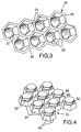
- the first forming roller 18 includes an outer shell 23 having a peripheral surface (Figure 3 illustrates a small segment of the peripheral surface of the first forming roller 18) including a lattice surface 20 on intersecting ridges, a multiplicity of recessed surfaces defining sockets 21 in a predetermined pattern recessed from the lattice surface 20, and surfaces defining air passageways 22 generally centrally through the recessed surfaces within the sockets 21 that extend to the inner surface of the shell 23.
- the second forming roller 19 ( Figure 4 illustrates a small segment of the peripheral surface of the second forming roller 19) includes a multiplicity of posts 24 radially projecting in the same predetermined pattern in which the sockets 21 are disposed and having distal end portions adapted to project into the sockets 21 in meshing relationship with the sheet 12 of fibers therebetween.
- the forming rollers 18 and 19 are mounted in axially parallel relationship with some of the posts 24 in meshing relationship with some of the sockets 21 in the manner of gear teeth.
- the forming rollers 18 and 19 are rotated and the sheet 12 of fibers is fed longitudinally between the meshed portions of the posts 24 and sockets 21 to generally conform the sheet 12 of fibers to the periphery of the first forming roller 18, thereby forming the arcuate portions 14 of the sheet 12 of fibers in the spaces between the distal ends of the posts 24 and the recessed surfaces defining the sockets 21 and the anchor portions 15 of the sheet 12 of fibers along the lattice surface 20.
- the formed sheet 12 of fibers is then retained along the peripheral surface of the first forming roller 18 for a predetermined distance after movement past the meshing portions of the posts 24 and sockets 21 primarily by drawing air into the first forming roller 18 through the air passageways 22.
- Molten thermoplastic material melted in an extruder 26 is extruded through a slot die 27 onto the anchor portions 15 of the sheet 12 of fibers along that predetermined distance to form at least a portion of the backing layer 16 around the anchor portions 15 of the sheet 12 of fibers with the arcuate portions 14 of the sheet 12 of fibers projecting from a front surface of the backing layer 16.
- the thermoplastic material in the backing layer 16 is then cooled and solidified by passing it around the surface of a cooling roll 30.
- the extruder could be adapted so that the extrudate is multi layer with tie layer resins known to those skilled in the art such as EAA, EVA, PE, etc., or an elastomer layer with polypropylene skins.
- the peripheral shell 23 of the first forming roller 18 is heated (e.g., to about 127 degrees Centigrade or 260 degrees Fahrenheit) by fixed radiant heaters 32 and 33 on its opposite sides, so that the peripheral shell 23 will not act as a heat sink which solidifies the thermoplastic material before the extruded thermoplastic material and the anchor portions of the fibers are fully bonded together.
- the inner surface of the shell 23 has a black oxide coating to facilitate heating by the heater 33 which is the primary heat source.
- a chrome coating on the peripheral surface of the forming roller, that aids release of the formed sheet of fibers, is resistive to heating by the radiant heater 32.
- Air heated to a temperature substantially above ambient temperature is supplied along the peripheral surface of the shell 23 between the second forming roller 19 and the cooling roller 30 to prevent the first forming roller 18 from being cooled excessively by air being drawn into the air passageways 22 to help retain the formed sheet 12 of fibers along that peripheral surface.
- That heated air is supplied along that peripheral surface by a heater fan 38 blowing the air through a heater 39 and out a nozzle 40 spaced closely above it so that heated air will be drawn into the air passageways 22.
- the source of air for the heater fan 38 can be only the atmosphere as illustrated, or the heated air which is pulled through the air passageways 22 into the first forming roller 18 by a suction fan 36 can be recycled by means not shown to provide at least a portion or all of the supply air for the heater fan 38.
- the peripheral shell 23 could be heated by means other than the fixed heaters 32 and 33, such as induction heating.
- the first forming roller includes the outer shell 23, circular end plates 41 attached to the opposite ends of the shell 23, and bearings 42 that afford rotation of the shell 23 and circular end plates 41 on a hollow cylindrical shaft 43 included in a fixed central air handling portion 44.
- the fixed central air handling portion 44 includes means for allowing air to be pulled through the air passageways 22 along a portion of the shell 23 moving from the second forming roller 19 to the cooling roller 30, and for restricting movement of air into the air passageways 22 along the rest of the shell 23.
- That means includes two radially projecting axially extending baffles 46 mounted on the shaft 43 which extend from the shaft 43 to the inner surface of the shell 23, one extending toward the second forming roller 19 and the other extending toward the cooling roller 30, and an axially extending air inlet slot 48 through the shaft 43 between the baffles 46. Air can be pulled by the suction fan 36 through the air passageways 22 between the baffles 46 and through the slot 48 into the opening at the center of the shaft 43 which is connected by a hose 50 to the inlet to the suction fan 36.
- the means in the fixed central air handling portion 44 for restricting movement of air into the air passageways 22 along the rest of the shell 23 comprises the baffles 46 which separate those air passageways from the slot 48.
- the sockets 21 have hexagonal inlet openings and are disposed in an array so that the lattice surface 20 has a uniform width between the sockets 21. It has been found that to get good bonding between the fibers and the backing layer 16 along that lattice surface 20, the lattice surface 20 should have a width of at least 0.025 inch or 0.063 centimeter between adjacent sockets 21, with a width of at least about 0.028 inch or 0.071 centimeter between adjacent sockets 21 being preferred.
- the sockets are defined by planar surfaces disposed in hexagonal patterns, which planar surfaces are tapered inwardly toward the inner portions of the sockets 21, and the air passageways 22 are defined by a cylindrical surface.
- the air passageways 22 have a cross sectional area that is large compared to the area of the sockets 21 in the plane of the lattice surface 20, and could be almost as large as that inlet area.
- the surfaces defining the sockets 21 are smooth and are chrome plated to facilitate release of a formed sheet 12 of fibers from within the sockets.
- the posts 24 have hexagonal tapered side surfaces 60 around their bases and cylindrical surfaces 62 around their distal ends that are adapted to project into the sockets 21 with the sheet 12 of fibers therebetween.
- the posts 24 are disposed in the same array as the sockets 21.
- the first and second forming members are biased together with air cylinders (not shown) so that the sheet 12 of fibers provides the spacing between the surfaces of the posts 24 and sockets as the sheet 12 of moves therebetween. Alternatively, a fixed gap could provide that spacing.
- the surfaces 60 and 62 of the posts 24 are also smooth and chrome plated to facilitate release from the formed sheet 12 of fibers.
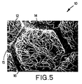
- Figure 5 is a photograph at 15 times magnification of a fragment of a sheet of loop material 10 according to the present invention that was made using the cavities 21 and posts 24 illustrated in Figures 3 and 4.
- the sheet of loop material 10 has arcuate portions 14 of the sheet 12 of fibers projecting in generally a hexagonal pattern in the same direction from anchor portions 15 of the sheet 12 of fibers, and spaced anchor portions 15 of the sheet of fibers 12 bonded in a backing layer 16 with the arcuate portions 14 of the sheet 12 of fibers projecting from the front surface of the backing layer 16.
- a sheet of loop material according to the present invention was made using the method illustrated in figure 1. Cut 6 denier polypropylene fibers 4.76 centimeters (1.875 inches) long obtained under the commercial designation "6d, T-110 1 7/8" from Hercules Inc., Covington, GA were formed, using the carding machine 17, into the longitudinal continuous sheet 12 of fibers which had a basis weight of 42 grams per square meter with the majority of the fibers (i.e. at least 90 percent) oriented in its longitudinal or machine direction. That sheet 12 of fibers was fed into the nip between the first and second forming rolls 18 and 19.
- the recessed surfaces defining the sockets and the posts 24 of the intermeshing forming rolls 18 and 19 were shaped to form along the length of the sheet 12 of fibers a honeycomb matrix of hexagonal pillowed projecting arcuate portions 14 of the sheet 12 of fibers, with each projecting arcuate portion 14 being hexagonal in shape around its periphery, about 5 mm wide, and 2 mm high, surrounded by an anchor portion 15 about 1 mm wide (see figures 4 and 5).
- the formed sheet 12 of fibers had a basis weight of 42 grams per square meter.
- Polypropylene material commercially designated Shell SRD7-560 was extruded by the extruder 26 through the die 27 at a melt temperature of 508 degrees F. and onto the anchor portions 15 of the formed sheet 12 of fibers at the nip between the first forming roller 18 and the cooling roller 30 in an amount appropriate to form a thermoplastic backing layer 16 weighing 50 grams per square meter with anchor portions 15 of the formed sheet 12 of fibers embedded therein.
- the outer shell 23 of the first forming roller 18 was heated by the heaters 32 and 33 to an outer surface temperature of approximately 263 F while running at a line speed of 60 fpm.
- Heating the outer surface of the first forming roller 18 was found necessary in order to securely bond the anchor portions 15 of the formed sheet 12 of fibers to the thermoplastic backing layer 16, with an outer surface temperature in the range of 260 to 268 degrees Fahrenheit or 127 to 131 degrees Centigrade being required under the conditions described above to get an adequate bond without melting the fibers in the arcuate portions 14 of the sheet 12 of fibers.
- the bond thus produced was uniform, translucent and film-like.
- air heated to about 104 degrees Centigrade or 220 degrees Fahrenheit was supplied at the surface of the first forming roll 18.
- the sheet of loop material 10 formed at the nip between the first forming roll 18 and the cooling roller 30 was then moved 200 degrees around the periphery of the cooling roller 30 which was at a temperature of about 32 degrees Centigrade or 90 degrees Fahrenheit to ensure adequate cooling of the thermoplastic backing layer 16.
- the resultant sheet of loop material 10 had soft, pillow like arcuate portions 14 due to the ability of air moving into the air passageways to hold the arcuate portions 14 of the formed sheet 12 of fibers away from the harsh heat of the molten thermoplastic material before it solidified.
- the finished sheet of loop material 10 was easily and firmly engaged by the hook material of the type described in U.S. Patent No. 4,894,060 issued Jan. 16, 1990.
- a sheet of loop material was formed in the same manner described in the above example except that the suction fan 36 was shut off so that no air was drawn through the air passageways 22.
- the sheet of loop material formed was not acceptable because acceptable uniform pillow-like projecting arcuate portions of the sheet of fibers could not be made at speeds greater than 0.3 meters per second.
- Loop material was formed in the same manner described in the above example, except that a 1.8 mil cast polypropylene film with a pre-printed pattern was fed around the cooling roll 30 along the path indicated by the dotted line 52 and became a portion of the backing layer 16 that was laminated by the extruded layer of thermoplastic material to the anchor portions 15 of the sheet 12 of fibers.
- the pre-printed pattern was found to be easily visible through the fibers.
- cut fibers could be used in the above example, particularly including cut bi-component fibers 4.76 centimeters (1.875 inches) long having a polyethylene sheath and a polypropylene core such as the fibers commercially designated 6d "T-425 1 7/8" available from Hercules Corporation, Wilmington, DE.
- Such fibers used at about the same basis weight to form a sheet of loop material that had improved bond strength and affinity for certain hook materials.
- the types and materials of the fibers that could be used in the sheet 12 of fibers, the basis weights for sheets 12 of fibers that could be used, and the material for the backing layer 16 are generally the same as those discussed in U.S. Patent No. 5,256,231 (Gorman et al).
- Figure 6 illustrates a second embodiment of a method and equipment for making a loop material 70 in which the method and equipment for forming the sheet of fibers and carrying it on the surface of the first forming roller 18 is the same as that described above and is indicated by the same reference numeral, but in which there is illustrated a different means for attaching a layer of material 72 to the anchor portions of the sheet of 12 fibers to form at least a portion of a backing attached to the anchor portions of the sheet of fibers with the arcuate portions of the sheet of fibers projecting from a front surface of the backing.
- the layer of material 72 which could be a woven or non-woven layer of fibers or a polymeric film that is either non-porous, porous, or microporous so that it is impermeable to liquid but passes air and vapor, is attached to those anchor portions in a nip either by heat and pressure applied by a heated roller 74, or, alternatively, by spraying an adhesive, such as a hot melt adhesive, from a spray assembly 76 over the surface of the layer of material 72 to be attached to the anchor portions.
- an adhesive such as a hot melt adhesive
- a sheet of loop material according to the present invention was made using the method illustrated in Figure 6.
- the longitudinal sheet 12 of fibers was formed in the same manner described in the first example above.
- the layer of material 72 was the water impermeable, water vapor permeable microporous polypropylene film sold under the trade designation "XMP 5031" by Minnesota Mining and Manufacturing Company, St. Paul, Minnesota. That microporous film used for the layer of material 72 is similar to the microporous films described in the U.S. Patents Nos. 4,539,256; 4,726,989; 4,824,718; 4,902,553; 5,260,360; and 5,352,513.
- the microporous film layer 72 was attached to the anchor portions of the sheet 12 of fibers by thermal bonding by heating the roller 74 to temperature in the range of about 180 to 200 degrees Fahrenheit and without the use of adhesive from the spray assembly 76.
- the sheet of loop material 70 produced was breathable (i.e., it could pass air or water vapor) but was liquid impermeable. It was suitable for use as the loop fastener portion of a hook and loop attachment system on a disposable diaper.
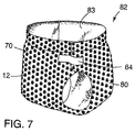
- the breathable but liquid impermeable sheet of loop material 70 produced could be used as the entire outer backsheet 80 of a disposable diaper 82 with the fibers 12 along its outer surface.
- the diaper 82 includes a conventional inner liquid absorbing layer 83.
- the backsheet 80 for the diaper 82 formed by the loop material 70 provides, with the use of a length of hook material 84, both part of means for refastenably attaching the diaper 82 to an individual and means for securing the diaper 82 in a tightly wrapped condition for disposal after the diaper 82 has been soiled.
- the length of hook material 84 is of a polymeric material that can be thermally bonded to the layer of microporous film material 72 and to the sheet 12 of fibers, it can be attached by having one of its end portions thermally bonded to the sheet of loop material 70, thereby eliminating need to use adhesive for that purpose.
- first and second forming members could be made with axially extending ridges like the axially extending ridges 28 on the corrugating members or rollers 26 and 27 described in U.S. Patent No. 5,256,231 (Gorman et al) with the air passageways opening into the recesses between the ridges and would help in high speed formation of sheet material of the type illustrated in U.S. Patent No. 5,256,231.
- a sheet of loop material having arcuate portions projecting from both sides of a backing could be formed by providing first and second forming rollers on both sides of the extruder die, and forming a sheet of fibers on each set of forming rollers so that the backing layer is extruded or otherwise attached onto the anchor portions of both sheets of fibers, in which case, if needed, cooling of the backing layer could be caused by air currents directed against its opposite sides.
Description
1 7/8" available from Hercules Corporation, Wilmington, DE. Such fibers used at about the same basis weight to form a sheet of loop material that had improved bond strength and affinity for certain hook materials.
Claims (11)
- A method for forming a sheet of loop material (10; 70) adapted to be cut into pieces to form loop portions for fasteners of the type having releasably engageable hook and loop portions, said method comprising:providing an elongate sheet (12) of fibers;forming the sheet (12) of fibers to have arcuate portions (14) projecting in the same direction from spaced anchor portions (15) of the sheet (12) of fibers, said forming step comprising the steps of:providing first and second generally cylindrical forming members (18, 19) each having an axis, the peripheral surface of said first forming member (18) being defined by surfaces (20) on ridges, recessed surfaces defining recesses (21), and surfaces defining air passageways (22) through said recessed surfaces, and said second forming member (19) including a multiplicity of projections (24) radially projecting in said predetermined pattern and having distal end portions adapted to project into said recesses (21) in meshing relationship with the sheet (12) of fibers therebetween;mounting the forming members (18, 19) in axially parallel relationship with some of the projections (24) in meshing relationship with some of the recesses (21);rotating the forming members (18, 19); andfeeding the sheet (12) of fibers longitudinally between the meshed portions of the projections (24) and recessed surfaces to generally conform the sheet (12) of fibers to the periphery of the first forming member (18) and form the arcuate portions (14) of the fibers in the spaces between the distal ends of the projections (24) and the recessed surfaces defining the receses (21) and the anchor portions (15) of the fibers along the surfaces (20) on ridges;retaining the formed sheet (12) of fibers along the peripheral surface of the first forming member (18) for a predetermined distance after movement past the meshing portions of the projections (24) and recessed surfaces primarily by drawing air through said air passageways (22); andattaching a layer of material to the anchor portions (15) of the sheet (12) of fibers to form at least a portion of a backing layer (16) attached to the spaced anchor portions (15) of the sheet (12) of fibers with the arcuate portions (14) of the sheet (12) of fibers projecting from a front surface of the backing layer (16).
- A method for forming a sheet of loop material (10; 70) according to claim 1 further including the steps of:heating the first forming member (18) to a temperature substantially above ambient temperature; andsupplying a source of heated air substantially above ambient temperature to be drawn into said air passageways (22) during said retaining step.
- A method for forming a sheet of loop material (10; 70) according to claim 1 or 2 wherein said ridges intersect so that the surfaces on the ridges form a lattice surface (20), the recessed surfaces define sockets (21) in a predetermined pattern recessed from said lattice surface (20), and said projections on said second forming member (19) are a multiplicity of radially projecting posts (24) having distal end portions adapted to project into said sockets (21) in meshing relationship with the sheet (12) of fibers therebetween.
- A method for forming a sheet of loop material (10; 70) according to claim 3 wherein said lattice surface (20) is of generally uniform width of over 0.06 centimeter (0.025 inch) and is disposed to define hexagonal inlet openings to said sockets (21) with said inlet openings to said sockets (21) having a width in the range of about 0.25 to 1.3 centimeters (0.1 to 0.5 inch).
- A method for forming a sheet of loop material (10; 70) according to claim 1 wherein said step of providing the elongate sheet (12) of fibers comprises the step of carding cut fibers to provide a sheet (12) of fibers having a basis weight in the range of 15 to 80 grams per square meter with over 50 percent of the fibers extending longitudinally of the sheet (12) of fibers.
- A method for forming a sheet of loop material (10) according to claim 1 wherein said attaching step comprises extruding molten thermoplastic material onto the anchor portions (15) to form at least a portion of the backing layer (16) around the spaced anchor portions (15) of the sheet (12) of fibers with the arcuate portions (14) of the sheet (12) of fibers projecting from a front surface of the backing layer (16); and cooling and solidifying the layer of thermoplastic material, and said method further includes the step of positioning a surface of a sheet of backing material (52) intended to be incorporated into the backing layer (16) closely adjacent the spaced anchor portions (15), and wherein in said extruding step the molten thermoplastic material is extruded onto both the anchor portions (15) of the fibers and onto the adjacent surface of the sheet of backing material (52), and said method includes the step of pressing the sheet of backing material (52) and the anchor portions (15) of the fibers into intimate contact with the molten thermoplastic material.
- A method for forming a sheet of loop material (10) according to claim 6 further including:providing a generally cylindrical cooling roll (30) having an axis; andmounting the cooling roll (30) in axially parallel relationship with the forming members (18, 19) with the periphery of the cooling roll (30) closely spaced from and defining a nip with the periphery of the first forming member (18) at the predetermined distance from the meshing portions of said forming members (18, 19); andsaid extruding step extrudes the molten thermoplastic material onto the anchor portions (15) of the fibers along the periphery of the first forming member (18) adjacent the nip between the cooling roll (30) and the first forming member (18).
- Equipment for forming a sheet of loop material (10; 70) adapted to be cut into pieces to form loop portions for fasteners of the type having releasably engageable hook and loop portions, said equipment comprising:means for providing an elongate sheet (12) of fibers;means for forming the sheet (12) of fibers to have arcuate portions (14) projecting in the same direction from spaced anchor portions (15) of the sheet (12) of fibers, said means for forming comprising:first and second generally cylindrical forming members (18, 19) each having an axis, the peripheral surface of said first forming member (18) being defined by surfaces (20) on ridges, recessed surfaces defining recesses (21), and surfaces defining air passageways (22) through said recessed surfaces, and said second forming member (19) including a multiplicity of projections (24) radially projecting in said predetermined pattern and having distal end portions adapted to project into said recesses (21) in meshing relationship with the sheet (12) of fibers therebetween;means for mounting the forming members (18, 19) in axially parallel relationship with some of the projections (24) in meshing relationship with some of the recesses (21);means for rotating the forming members (18, 19); andmeans for feeding the sheet (12) of fibers longitudinally between the meshed portions of the projections (24) and recessed surfaces to generally conform the sheet (12) of fibers to the periphery of the first forming member (18) and form the arcuate portions (14) of the fibers in the spaces between the distal ends of the projections (24) and the recessed surfaces defining the sockets (21) and the anchor portions (15) of the fibers along the surfaces (20) on the ridges;means for retaining the formed sheet (12) of fibers along the peripheral surface of the first forming member (18) for a predetermined distance after movement past the meshing portions of the projections (24) and recessed surfaces comprising means for drawing air through said air passageways (22); andmeans (26, 27; 76) for attaching a layer of material to the anchor portions (15) of the sheet (12) of fibers to form at least a portion of a backing layer (16) attached to the spaced anchor portions (15) fibers with the arcuate portions (14) of the sheet (12) of fibers projecting from a for surface of the backing layer (16).
- Equipment for forming a sheet of loop material (10; 70) according to claim 8 further including:means (33) for heating the first forming member (18) to a temperature substantially above ambient temperature; andmeans (38, 39, 40) for supplying a source of heated air substantially above ambient temperature to be drawn into said air passageways (22) by said means for retaining to restrict cooling of said first forming member (18).
- Equipment for forming a sheet of loop material (10) according to claim 9 further including a generally cylindrical cooling roll (30) having an axis; and means for mounting the cooling roll (30) in axially parallel relationship with the forming members (18, 19) with the periphery of the cooling roll (30) closely spaced from and defining a nip with the periphery of the first forming member (18) at the predetermined distance from the meshing portions of said forming members (18, 19); and said means for attaching includes means (26, 27) for extruding molten thermoplastic material onto the anchor portions (15) of the fibers along the periphery of the first forming member (18) adjacent the nip between the cooling roll (30) and the first forming member (18).
- Equipment for forming a sheet of loop material (10; 70) according to claim 8 wherein the ridges intersect so that the surfaces on the ridges form a lattice surface (20), the recessed surfaces define sockets (21) in a predetermined pattern recessed from said lattice surface (20), and said projections on said second forming member (19) are a multiplicity of radially projecting posts (24) having distal end portions adapted to project into said sockets (21) in meshing relationship with the sheet (12) of fibers therebetween.
Applications Claiming Priority (3)
| Application Number | Priority Date | Filing Date | Title |
|---|---|---|---|
| US698282 | 1996-08-14 | ||
| US08/698,282 US5904793A (en) | 1996-08-14 | 1996-08-14 | Method and equipment for rapid manufacture of loop material |
| PCT/US1997/012387 WO1998006290A1 (en) | 1996-08-14 | 1997-07-16 | Method and equipment for rapid manufacture of loop material |
Publications (2)
| Publication Number | Publication Date |
|---|---|
| EP0921738A1 EP0921738A1 (en) | 1999-06-16 |
| EP0921738B1 true EP0921738B1 (en) | 2002-03-13 |
Family
ID=24804620
Family Applications (1)
| Application Number | Title | Priority Date | Filing Date |
|---|---|---|---|
| EP97934972A Expired - Lifetime EP0921738B1 (en) | 1996-08-14 | 1997-07-16 | Method and equipment for rapid manufacture of loop material |
Country Status (14)
| Country | Link |
|---|---|
| US (1) | US5904793A (en) |
| EP (1) | EP0921738B1 (en) |
| JP (1) | JP2001502928A (en) |
| KR (1) | KR100488262B1 (en) |
| CN (1) | CN1227473A (en) |
| AR (1) | AR009042A1 (en) |
| AU (1) | AU715930B2 (en) |
| BR (1) | BR9711143A (en) |
| CA (1) | CA2261734A1 (en) |
| DE (1) | DE69711057T2 (en) |
| ES (1) | ES2170406T3 (en) |
| IL (1) | IL128168A (en) |
| TW (1) | TW344654B (en) |
| WO (1) | WO1998006290A1 (en) |
Families Citing this family (60)
| Publication number | Priority date | Publication date | Assignee | Title |
|---|---|---|---|---|
| US6387471B1 (en) * | 1999-03-31 | 2002-05-14 | Kimberly-Clark Worldwide, Inc. | Creep resistant composite elastic material with improved aesthetics, dimensional stability and inherent latency and method of producing same |
| KR20010077591A (en) * | 2000-02-03 | 2001-08-20 | 복성해 | A novel metalloprotease and a gene thereof derived from Aranicola proteolyticus |
| US20020042962A1 (en) * | 2000-02-24 | 2002-04-18 | Willman Kenneth William | Cleaning sheets comprising a polymeric additive to improve particulate pick-up and minimize residue left on surfaces and cleaning implements for use with cleaning sheets |
| US6453591B1 (en) * | 2000-07-20 | 2002-09-24 | Cooley, Incorporated | System and method for creating a message display |
| US6756327B2 (en) | 2000-10-31 | 2004-06-29 | Kimberly-Clark Worldwide, Inc. | Loop fastening component made from thermally retracted materials |
| DE10126143A1 (en) | 2001-05-30 | 2002-12-12 | Freudenberg Carl Kg | Laminate and process for its manufacture |
| KR20040010706A (en) * | 2001-06-12 | 2004-01-31 | 벨크로 인더스트리스 비.브이. | Loop materials for touch fastening |
| DE10161744A1 (en) * | 2001-12-15 | 2003-06-18 | Werner Jahn | Cling type plastic fastener strip manufacture involves pin creation by compression of plastic strip into holes in a rubber cover on a metal roll then shaping of heads on pins |
| US20030171051A1 (en) * | 2002-03-08 | 2003-09-11 | 3M Innovative Properties Company | Wipe |
| KR100850458B1 (en) * | 2002-06-28 | 2008-08-07 | 삼성테크윈 주식회사 | Smart label and method for making it |
| US20040063369A1 (en) * | 2002-09-30 | 2004-04-01 | Jung Yeul Ahn | Nonwoven loop material and process and products relating thereto |
| US7465366B2 (en) * | 2002-12-03 | 2008-12-16 | Velero Industries B.V. | Needling loops into carrier sheets |
| US20050217092A1 (en) * | 2002-12-03 | 2005-10-06 | Barker James R | Anchoring loops of fibers needled into a carrier sheet |
| US20050196580A1 (en) * | 2002-12-03 | 2005-09-08 | Provost George A. | Loop materials |
| CN100577053C (en) * | 2002-12-03 | 2010-01-06 | 维尔克罗工业公司 | The acupuncture carrier sheet is to form ring |
| US20050196583A1 (en) * | 2002-12-03 | 2005-09-08 | Provost George A. | Embossing loop materials |
| US8753459B2 (en) * | 2002-12-03 | 2014-06-17 | Velcro Industries B.V. | Needling loops into carrier sheets |
| US7052565B2 (en) * | 2003-01-27 | 2006-05-30 | 3M Innovative Properties Company | Web constructions with severed elongate strands |
| EP1579779B1 (en) * | 2004-03-22 | 2006-10-18 | Nordenia Deutschland Gronau GmbH | Multi-layer fabric for hook fastener, especially for diaper fastener |
| GB0409253D0 (en) * | 2004-04-26 | 2004-05-26 | Lewmar Ltd | Winch and winch drum |
| FR2870436B1 (en) * | 2004-05-21 | 2006-07-14 | Aplix Sa | FILAMENT WITH INDIVIDUAL FILAMENTS ANCHORS |
| US20060019579A1 (en) * | 2004-07-26 | 2006-01-26 | Braunschweig Ehrich J | Non-loading abrasive article |
| MX2007007980A (en) * | 2004-12-30 | 2007-08-22 | 3M Innovative Properties Co | Abrasive article and methods of making same. |
| US7562426B2 (en) * | 2005-04-08 | 2009-07-21 | Velcro Industries B.V. | Needling loops into carrier sheets |
| MY146975A (en) * | 2005-04-11 | 2012-10-15 | Oji Nepia Co Ltd | Disposable pant-type diaper |
| US7252694B2 (en) * | 2005-08-05 | 2007-08-07 | 3M Innovative Properties Company | Abrasive article and methods of making same |
| US7258705B2 (en) * | 2005-08-05 | 2007-08-21 | 3M Innovative Properties Company | Abrasive article and methods of making same |
| US8241263B2 (en) | 2005-08-26 | 2012-08-14 | Medline Industries, Inc. | Absorbent article |
| US7393269B2 (en) * | 2005-09-16 | 2008-07-01 | 3M Innovative Properties Company | Abrasive filter assembly and methods of making same |
| US7244170B2 (en) * | 2005-09-16 | 2007-07-17 | 3M Innovative Properties Co. | Abrasive article and methods of making same |
| US7390244B2 (en) * | 2005-09-16 | 2008-06-24 | 3M Innovative Properties Company | Abrasive article mounting assembly and methods of making same |
| EP1902698A1 (en) * | 2006-09-22 | 2008-03-26 | 3M Innovative Properties Company | Landing zone for mechanical fasteners of disposable products, process for manufacturing thereof and process for manufacturing disposable products |
| JP2008087082A (en) * | 2006-09-29 | 2008-04-17 | Three M Innovative Properties Co | Grinding tool for sucking dust |
| ES2541151T3 (en) | 2006-10-27 | 2015-07-16 | Paul Hartmann Ag | Absorbent incontinence article with improved closure system |
| US20080113152A1 (en) * | 2006-11-14 | 2008-05-15 | Velcro Industries B.V. | Loop Materials |
| US7452265B2 (en) * | 2006-12-21 | 2008-11-18 | 3M Innovative Properties Company | Abrasive article and methods of making same |
| MX2009008242A (en) | 2007-02-02 | 2009-08-12 | Donaldson Co Inc | Air filtration media pack, filter element, air filtration media, and methods. |
| WO2008154300A1 (en) * | 2007-06-07 | 2008-12-18 | Velcro Industries B.V. | Anchoring loops of fibers needled into a carrier sheet |
| US8545589B2 (en) | 2007-06-26 | 2013-10-01 | Donaldson Company, Inc. | Filtration media pack, filter element, and methods |
| ES2542991T3 (en) | 2007-08-02 | 2015-08-13 | Paul Hartmann Ag | Disposable absorbent incontinence diaper |
| MX2010008530A (en) | 2008-02-04 | 2010-08-30 | Donaldson Co Inc | Method and apparatus for forming fluted filtration media. |
| BRPI0915931B1 (en) | 2008-07-25 | 2020-03-31 | Donaldson Company, Inc. | PACKAGES OF PREGUE FILTERING AGENTS |
| JP5711230B2 (en) * | 2009-08-03 | 2015-04-30 | ドナルドソン カンパニー,インコーポレイティド | Method and apparatus for forming fluted filtration media having tapered flutes |
| CN105536383B (en) | 2010-01-25 | 2019-12-24 | 唐纳森公司 | Pleated filter media with wedge shaped flutes |
| WO2012054591A1 (en) | 2010-10-19 | 2012-04-26 | Love Daniel B | Absorbent articles and methods of manufacturing the same |
| CN102454050A (en) * | 2010-10-26 | 2012-05-16 | 台湾百和工业股份有限公司 | Hook and loop fastener flock surface and method and equipment for producing same |
| TWI457088B (en) | 2010-10-26 | 2014-10-21 | Taiwan Paiho Ltd | Velcro with hair surface manufacturing methods, manufacturing equipment and velcro hair surface |
| US9119443B2 (en) | 2011-08-25 | 2015-09-01 | Velcro Industries B.V. | Loop-engageable fasteners and related systems and methods |
| WO2013028251A1 (en) | 2011-08-25 | 2013-02-28 | Velcro Industries B.V | Hook-engageable loop fasteners and related systems and methods |
| USD716938S1 (en) | 2011-10-19 | 2014-11-04 | Medline Industries, Inc. | Absorbent core |
| KR101135136B1 (en) * | 2011-11-17 | 2012-04-16 | 주식회사 폴리쉘 | Apparatus for manufacturing cushion for packaging |
| US9475205B2 (en) | 2012-05-18 | 2016-10-25 | 3M Innovative Properties Company | Method of making a mechanical fastener and apparatus including a roller with protrusions |
| US9486368B2 (en) | 2013-12-05 | 2016-11-08 | Medline Industries, Inc. | Disposable hygienic article with means for diagnostic testing |
| CN105828684B (en) | 2013-12-18 | 2019-04-19 | 3M创新有限公司 | Cleaning article |
| US9622922B2 (en) | 2014-04-21 | 2017-04-18 | Medline Industries, Inc. | Stretch breathable protective absorbent article using bilaminate |
| US10226388B2 (en) | 2014-04-21 | 2019-03-12 | Medline Industries, Inc. | Stretch breathable protective absorbent article using tri-laminate |
| HUE055737T2 (en) | 2015-07-07 | 2021-12-28 | Mitsubishi Chem Corp | Method for producing fiber-reinforced resin molding material |
| JP2019524307A (en) | 2016-08-08 | 2019-09-05 | スリーエム イノベイティブ プロパティズ カンパニー | Loop material sheet, method and apparatus for forming the same |
| CN109394421B (en) * | 2018-10-12 | 2021-07-06 | 宜城成雄织造有限公司 | Based on multilayer diaper production is with compaction equipment that kills virus |
| CN114619640A (en) * | 2022-04-22 | 2022-06-14 | 天宫氢能材料科技(东莞)有限公司 | Preparation equipment and preparation method of perfluorosulfonic acid proton membrane |
Citations (1)
| Publication number | Priority date | Publication date | Assignee | Title |
|---|---|---|---|---|
| WO1992020251A1 (en) * | 1991-05-20 | 1992-11-26 | The Procter & Gamble Company | Nonwoven female component for refastenable fastening device and method of making the same |
Family Cites Families (22)
| Publication number | Priority date | Publication date | Assignee | Title |
|---|---|---|---|---|
| US3182346A (en) * | 1963-04-29 | 1965-05-11 | Gen Foods Corp | Cleaning article and method of manufacture |
| US3546754A (en) * | 1968-08-12 | 1970-12-15 | George H Erb | Separable fastener |
| US3723213A (en) * | 1970-08-18 | 1973-03-27 | Rohm & Haas | Method of making non-woven pile fabric |
| US3867243A (en) * | 1970-12-22 | 1975-02-18 | Phillips Petroleum Co | Laminate structure suitable for carpet use and method of making |
| US3892613A (en) * | 1971-07-22 | 1975-07-01 | Int Paper Co | Method of making corrugated paperboard |
| GB1376782A (en) * | 1972-02-22 | 1974-12-11 | Atomic Energy Authority Uk | Apparatus for welding together superimposed sheets of thermoplastic material |
| BR7905400A (en) * | 1978-10-05 | 1980-05-20 | Mitsubishi Heavy Ind Ltd | LOWER CYLINDER ON A SINGLE MACHINE |
| US4609581A (en) * | 1985-04-15 | 1986-09-02 | Minnesota Mining And Manufacturing Company | Coated abrasive sheet material with loop attachment means |
| US4761318A (en) * | 1985-04-15 | 1988-08-02 | Minnesota Mining And Manufacturing Company | Loop fastener portion with thermoplastic resin attaching and anchoring layer |
| US4770917A (en) * | 1985-07-31 | 1988-09-13 | Minnesota Mining And Manufacturing Company | Sheet material used to form portions of fasteners |
| US5032122A (en) * | 1987-04-24 | 1991-07-16 | The Procter & Gamble Company | Loop fastening material for fastening device and method of making same |
| US5380313A (en) * | 1987-06-19 | 1995-01-10 | The Proctor & Gamble Company | Loop fastening material for fastening device and method of making same |
| US5256231A (en) * | 1988-05-13 | 1993-10-26 | Minnesota Mining And Manufacturing Company | Method for making a sheet of loop material |
| AU622171B2 (en) * | 1988-05-13 | 1992-04-02 | Minnesota Mining And Manufacturing Company | Sheet material for forming the loop portion for hook and loop fasteners |
| US5254194A (en) * | 1988-05-13 | 1993-10-19 | Minnesota Mining And Manufacturing Company | Coated abrasive sheet material with loop material for attachment incorporated therein |
| FR2663621B2 (en) * | 1990-04-30 | 1993-05-21 | Capy Gilbert | DEVICE FOR PROGRESSIVE TIGHTENING OF DISSYMMETRIC FOLDES, MADE FROM A FILM, PRE-PREFORMED ON A TOOTHED WHEEL. |
| DE4016348C2 (en) * | 1990-05-21 | 1995-12-21 | Bp Chemicals Plastec Gmbh | Process for producing a composite fleece and use of a composite fleece produced in this way |
| US5316828A (en) * | 1991-04-25 | 1994-05-31 | Miller Ray R | Reinforced fluted medium and corrugated fiberboard made using the medium |
| PL171847B1 (en) * | 1991-05-20 | 1997-06-30 | Procter & Gamble | Receiving portion of a disconnectable fastener especially for clothing |
| JPH07213554A (en) * | 1994-02-04 | 1995-08-15 | New Oji Paper Co Ltd | Manufacture of sheet-type elastic combination |
| US5547531A (en) * | 1994-06-06 | 1996-08-20 | The Proctor & Gamble Company | Nonwoven female component for refastenable fastening device and method of making the same |
| US5614281A (en) * | 1995-11-29 | 1997-03-25 | Kimberly-Clark Corporation | Creped nonwoven laminate loop fastening material for mechanical fastening systems |
-
1996
- 1996-08-14 US US08/698,282 patent/US5904793A/en not_active Expired - Fee Related
-
1997
- 1997-07-16 BR BR9711143A patent/BR9711143A/en not_active IP Right Cessation
- 1997-07-16 DE DE69711057T patent/DE69711057T2/en not_active Expired - Fee Related
- 1997-07-16 KR KR10-1999-7001191A patent/KR100488262B1/en not_active IP Right Cessation
- 1997-07-16 CA CA002261734A patent/CA2261734A1/en not_active Abandoned
- 1997-07-16 WO PCT/US1997/012387 patent/WO1998006290A1/en active IP Right Grant
- 1997-07-16 EP EP97934972A patent/EP0921738B1/en not_active Expired - Lifetime
- 1997-07-16 AU AU38016/97A patent/AU715930B2/en not_active Ceased
- 1997-07-16 JP JP10509711A patent/JP2001502928A/en not_active Ceased
- 1997-07-16 ES ES97934972T patent/ES2170406T3/en not_active Expired - Lifetime
- 1997-07-16 CN CN97197222A patent/CN1227473A/en active Pending
- 1997-07-16 IL IL12816897A patent/IL128168A/en not_active IP Right Cessation
- 1997-07-22 TW TW086110382A patent/TW344654B/en active
- 1997-08-11 AR ARP970103632A patent/AR009042A1/en active IP Right Grant
Patent Citations (1)
| Publication number | Priority date | Publication date | Assignee | Title |
|---|---|---|---|---|
| WO1992020251A1 (en) * | 1991-05-20 | 1992-11-26 | The Procter & Gamble Company | Nonwoven female component for refastenable fastening device and method of making the same |
Also Published As
| Publication number | Publication date |
|---|---|
| IL128168A0 (en) | 1999-11-30 |
| CN1227473A (en) | 1999-09-01 |
| BR9711143A (en) | 1999-08-17 |
| DE69711057D1 (en) | 2002-04-18 |
| AR009042A1 (en) | 2000-03-08 |
| TW344654B (en) | 1998-11-11 |
| IL128168A (en) | 2001-07-24 |
| EP0921738A1 (en) | 1999-06-16 |
| JP2001502928A (en) | 2001-03-06 |
| KR100488262B1 (en) | 2005-05-11 |
| AU715930B2 (en) | 2000-02-10 |
| US5904793A (en) | 1999-05-18 |
| CA2261734A1 (en) | 1998-02-19 |
| WO1998006290A1 (en) | 1998-02-19 |
| ES2170406T3 (en) | 2002-08-01 |
| DE69711057T2 (en) | 2002-07-18 |
| KR20000029956A (en) | 2000-05-25 |
| AU3801697A (en) | 1998-03-06 |
Similar Documents
| Publication | Publication Date | Title |
|---|---|---|
| EP0921738B1 (en) | Method and equipment for rapid manufacture of loop material | |
| US5256231A (en) | Method for making a sheet of loop material | |
| US5616394A (en) | Sheet of loop material, and garments having such loop material incorporated therein | |
| US5611791A (en) | Sheet of loop material, and garments having such loop material incorporated therein | |
| US6942894B2 (en) | Methods for producing composite webs with reinforcing discrete polymeric regions | |
| US7238314B2 (en) | Polymer transfer apparatus, methods, and composite webs | |
| KR100489474B1 (en) | A mechenical fastener and a method for making a finger grip therefor | |
| CN100537221C (en) | Loop fabric and production method thereof | |
| KR100263360B1 (en) | Method for manufacturing refastenable fastening systems including a female loop fastening component and the products produced therefrom | |
| US6875710B2 (en) | Composite webs with reinforcing polymeric regions and elastic polymeric regions | |
| US20030087059A1 (en) | Composite webs with discrete elastic polymeric regions | |
| US6136405A (en) | Sheet material having a fibrous surface and method of making the same | |
| MXPA97001501A (en) | Leaf material that has a fibrous surface and method to make my | |
| EP0925770A2 (en) | Fastening device of disposable diaper | |
| JP3133045B2 (en) | Fastener system |
Legal Events
| Date | Code | Title | Description |
|---|---|---|---|
| PUAI | Public reference made under article 153(3) epc to a published international application that has entered the european phase |
Free format text: ORIGINAL CODE: 0009012 |
|
| 17P | Request for examination filed |
Effective date: 19990305 |
|
| AK | Designated contracting states |
Kind code of ref document: A1 Designated state(s): BE CH DE ES FR GB IT LI NL |
|
| 17Q | First examination report despatched |
Effective date: 20000307 |
|
| GRAG | Despatch of communication of intention to grant |
Free format text: ORIGINAL CODE: EPIDOS AGRA |
|
| GRAG | Despatch of communication of intention to grant |
Free format text: ORIGINAL CODE: EPIDOS AGRA |
|
| GRAG | Despatch of communication of intention to grant |
Free format text: ORIGINAL CODE: EPIDOS AGRA |
|
| GRAH | Despatch of communication of intention to grant a patent |
Free format text: ORIGINAL CODE: EPIDOS IGRA |
|
| GRAH | Despatch of communication of intention to grant a patent |
Free format text: ORIGINAL CODE: EPIDOS IGRA |
|
| REG | Reference to a national code |
Ref country code: GB Ref legal event code: IF02 |
|
| GRAA | (expected) grant |
Free format text: ORIGINAL CODE: 0009210 |
|
| AK | Designated contracting states |
Kind code of ref document: B1 Designated state(s): BE CH DE ES FR GB IT LI NL |
|
| PG25 | Lapsed in a contracting state [announced via postgrant information from national office to epo] |
Ref country code: NL Free format text: LAPSE BECAUSE OF FAILURE TO SUBMIT A TRANSLATION OF THE DESCRIPTION OR TO PAY THE FEE WITHIN THE PRESCRIBED TIME-LIMIT Effective date: 20020313 Ref country code: LI Free format text: LAPSE BECAUSE OF FAILURE TO SUBMIT A TRANSLATION OF THE DESCRIPTION OR TO PAY THE FEE WITHIN THE PRESCRIBED TIME-LIMIT Effective date: 20020313 Ref country code: CH Free format text: LAPSE BECAUSE OF FAILURE TO SUBMIT A TRANSLATION OF THE DESCRIPTION OR TO PAY THE FEE WITHIN THE PRESCRIBED TIME-LIMIT Effective date: 20020313 Ref country code: BE Free format text: LAPSE BECAUSE OF FAILURE TO SUBMIT A TRANSLATION OF THE DESCRIPTION OR TO PAY THE FEE WITHIN THE PRESCRIBED TIME-LIMIT Effective date: 20020313 |
|
| REG | Reference to a national code |
Ref country code: CH Ref legal event code: EP |
|
| REF | Corresponds to: |
Ref document number: 69711057 Country of ref document: DE Date of ref document: 20020418 |
|
| NLV1 | Nl: lapsed or annulled due to failure to fulfill the requirements of art. 29p and 29m of the patents act | ||
| REG | Reference to a national code |
Ref country code: ES Ref legal event code: FG2A Ref document number: 2170406 Country of ref document: ES Kind code of ref document: T3 |
|
| ET | Fr: translation filed | ||
| REG | Reference to a national code |
Ref country code: CH Ref legal event code: PL |
|
| PLBE | No opposition filed within time limit |
Free format text: ORIGINAL CODE: 0009261 |
|
| STAA | Information on the status of an ep patent application or granted ep patent |
Free format text: STATUS: NO OPPOSITION FILED WITHIN TIME LIMIT |
|
| 26N | No opposition filed |
Effective date: 20021216 |
|
| PGFP | Annual fee paid to national office [announced via postgrant information from national office to epo] |
Ref country code: ES Payment date: 20050727 Year of fee payment: 9 |
|
| PGFP | Annual fee paid to national office [announced via postgrant information from national office to epo] |
Ref country code: GB Payment date: 20060726 Year of fee payment: 10 |
|
| PGFP | Annual fee paid to national office [announced via postgrant information from national office to epo] |
Ref country code: DE Payment date: 20070831 Year of fee payment: 11 |
|
| PGFP | Annual fee paid to national office [announced via postgrant information from national office to epo] |
Ref country code: IT Payment date: 20070727 Year of fee payment: 11 |
|
| GBPC | Gb: european patent ceased through non-payment of renewal fee |
Effective date: 20070716 |
|
| PGFP | Annual fee paid to national office [announced via postgrant information from national office to epo] |
Ref country code: FR Payment date: 20070717 Year of fee payment: 11 |
|
| PG25 | Lapsed in a contracting state [announced via postgrant information from national office to epo] |
Ref country code: GB Free format text: LAPSE BECAUSE OF NON-PAYMENT OF DUE FEES Effective date: 20070716 |
|
| REG | Reference to a national code |
Ref country code: ES Ref legal event code: FD2A Effective date: 20070717 |
|
| PG25 | Lapsed in a contracting state [announced via postgrant information from national office to epo] |
Ref country code: ES Free format text: LAPSE BECAUSE OF NON-PAYMENT OF DUE FEES Effective date: 20070717 |
|
| PG25 | Lapsed in a contracting state [announced via postgrant information from national office to epo] |
Ref country code: DE Free format text: LAPSE BECAUSE OF NON-PAYMENT OF DUE FEES Effective date: 20090203 |
|
| REG | Reference to a national code |
Ref country code: FR Ref legal event code: ST Effective date: 20090331 |
|
| PG25 | Lapsed in a contracting state [announced via postgrant information from national office to epo] |
Ref country code: IT Free format text: LAPSE BECAUSE OF NON-PAYMENT OF DUE FEES Effective date: 20080716 Ref country code: FR Free format text: LAPSE BECAUSE OF NON-PAYMENT OF DUE FEES Effective date: 20080731 |