EP0920839B2 - Motor handpiece - Google Patents
Motor handpiece Download PDFInfo
- Publication number
- EP0920839B2 EP0920839B2 EP98122300A EP98122300A EP0920839B2 EP 0920839 B2 EP0920839 B2 EP 0920839B2 EP 98122300 A EP98122300 A EP 98122300A EP 98122300 A EP98122300 A EP 98122300A EP 0920839 B2 EP0920839 B2 EP 0920839B2
- Authority
- EP
- European Patent Office
- Prior art keywords
- handpiece
- motor
- working
- tool
- shaft
- Prior art date
- Legal status (The legal status is an assumption and is not a legal conclusion. Google has not performed a legal analysis and makes no representation as to the accuracy of the status listed.)
- Expired - Lifetime
Links
Images

Classifications
-
- A—HUMAN NECESSITIES
- A61—MEDICAL OR VETERINARY SCIENCE; HYGIENE
- A61C—DENTISTRY; APPARATUS OR METHODS FOR ORAL OR DENTAL HYGIENE
- A61C1/00—Dental machines for boring or cutting ; General features of dental machines or apparatus, e.g. hand-piece design
- A61C1/02—Dental machines for boring or cutting ; General features of dental machines or apparatus, e.g. hand-piece design characterised by the drive of the dental tools
- A61C1/06—Dental machines for boring or cutting ; General features of dental machines or apparatus, e.g. hand-piece design characterised by the drive of the dental tools with electric drive
-
- A—HUMAN NECESSITIES
- A61—MEDICAL OR VETERINARY SCIENCE; HYGIENE
- A61C—DENTISTRY; APPARATUS OR METHODS FOR ORAL OR DENTAL HYGIENE
- A61C1/00—Dental machines for boring or cutting ; General features of dental machines or apparatus, e.g. hand-piece design
- A61C1/08—Machine parts specially adapted for dentistry
- A61C1/14—Tool-holders, i.e. operating tool holders, e.g. burr holders
- A61C1/142—Operating tool blocking means
- A61C1/144—Operating tool blocking means constricting the operating tool, e.g. chuck
-
- A—HUMAN NECESSITIES
- A61—MEDICAL OR VETERINARY SCIENCE; HYGIENE
- A61C—DENTISTRY; APPARATUS OR METHODS FOR ORAL OR DENTAL HYGIENE
- A61C1/00—Dental machines for boring or cutting ; General features of dental machines or apparatus, e.g. hand-piece design
- A61C1/08—Machine parts specially adapted for dentistry
- A61C1/18—Flexible shafts; Clutches or the like; Bearings or lubricating arrangements; Drives or transmissions
Definitions
- the present invention generally relates to a motor handpiece for driving a tool coupleable to the motor handpiece.
- the present invention relates to a motor handpiece which can be used as a dental treatment handpiece or dental work handpiece.
- a generic work handpiece for dental purposes according to the preamble of claim 1 is for example from the DE-A1-44 06 855 the applicant and known in Fig. 5a shown.
- the illustrated work or motor handpiece 101 essentially comprises two handpiece parts 112, 113, wherein in the handpiece part 112 a motor, in the example shown, a brushless DC motor, and in the other handpiece part 113 a Schnelleinspannsystem for example a dental tool is arranged.
- the brushless DC motor comprises a yoke ring 102, a stator winding 103 and a rotor magnet 104.
- the motor is supplied via a supply line 118 current.
- the rotor magnet 104 is attached to a first shaft 109, wherein the shaft 109 is rotatably mounted in the handpiece part 112 by means of two ball bearings 114, 115. The shaft 109 is thus rotated together with the rotor magnet 104 upon activation of the motor in rotation.
- the quick-clamping system of the second handpiece part 113 essentially comprises a coaxially arranged in this handpiece part, sleeve-shaped slotted collet 105, which is coupled to a further drive shaft 110 and part thereof.
- the collet has at its outer end a conical outer shape which is complementary to a correspondingly shaped conical inner shape of a bearing sleeve 106, in which the collet 105 is arranged.
- the collet 105 is coupled to the housing of the second handle portion 113 via an actuating mechanism (not shown).
- the two handpiece parts 112 and 113 can be coupled with each other, in particular screwed.
- the two handpiece parts 112 and 113 are screwed together in the form of a bayonet closure.
- the aforesaid actuating mechanism may comprise, for example, a tightening rod which, upon rotation of the housing of the handpiece member 113 relative to the housing of the handpiece member 112, causes an axial displacement of the collet 105 to the right in a particular direction, with increasing longitudinal displacement of the collet 105 due to the complementary design thereof Outer or inner shapes of the collet 105 and the bearing sleeve 106 is compressed, so that located in the collet 105 tool 108, of which in Fig. 5a only the tool shank is indicated, is frictionally clamped in the collet 105.
- the longitudinal displacement of the collet 105 to the right against a spring force of a in Fig. 5a schematically illustrated spring 107 which may be, for example, a plate or coil spring.
- a relative rotation of the handpiece part 113 relative to the handpiece part 112 in the opposite direction leads correspondingly to a longitudinal displacement of the collet 105 to the left, which is supported by the spring force of the spring 107.
- This clamping mechanism is commonly referred to as a twist grip quick release mechanism.
- the Einspannmechanismust be on the DE-A1-44 06 855 directed.
- the previously described rotary grip quick release mechanism can also be configured such that instead of the bearing sleeve 106, the collet 105 is immovably disposed, while in contrast to Fig. 5a the bearing sleeve 106 is displaced in the longitudinal direction relative to the handpiece part 112 in accordance with the relative rotation of the handpiece part 113.
- the two handpiece parts 112 and 113 each have their own drive shafts 109, 110, which are rotatably mounted on the one hand in each case by means of two ball bearings 114, 115 and 116, 117 and on the other hand coupled with each other via a mechanical Mimehmersystem 111.
- Fig. 5a shown motor handpiece, however, it comes in particular at higher speeds due to unavoidable misalignment due to the mechanical coupling of the two drive shafts 109, 110 to a significantly increased noise. Furthermore, a total of four ball bearings 114-117 are required for this motor handpiece, which limit the speed of rotation in particular when using colletorless DC motors without additional cooling fan. However, additional cooling fans should be avoided because of the desired noise minimization.
- the maximum speed limit of the in Fig. 5a shown motor handpiece for an acceptable noise and heat development is currently at about 40,000 - 50,000 min -1 .
- Fig. 5b shows another known motor handpiece, which, for example, by the applicant sold under the name "SF motor spindle type 4010".
- This in Fig. 5b shown motor handpiece 101 has a one-piece housing 112, in which in turn a motor, such as a three-phase asynchronous motor or a brushless DC motor with a reflux ring 102, a stator winding 103 and a rotor magnet 104 is disposed.
- a motor such as a three-phase asynchronous motor or a brushless DC motor with a reflux ring 102
- a stator winding 103 a stator winding 103
- a rotor magnet 104 is mounted on a drive shaft 106.
- This drive shaft 106 is configured as a hollow shaft and has at its tool-side end a conical inner shape, which analogous to 5a is formed complementary to the conical outer shape of a sleeve-shaped slotted collet 105.
- This collet 105 is in turn part of a horrinspannsystems, which is disposed within the hollow shaft 106.
- the collet 105 is designed for this purpose in one piece with a further drive shaft 110 or coupled thereto, wherein the drive shaft 110 having at its other end an external thread 120 which engages in an internal thread of the hollow shaft 106.
- the drive shaft 110 can be operated with the collet 105 by a rotary knob 121 located at the rear of the motor handpiece 101, ie, screwed in or out in the longitudinal direction into the hollow shaft 106. Due to the conical outer shape of the collet 105, which is complementary to the conical inner shape of the hollow shaft 106, the collet 105 is compressed by screwing the collet 105 with the drive shaft 110 in the hollow shaft 106, thereby located in the collet 105 tool 108, of the in Fig. 5b only the tool shank is indicated, is held by the collet 105 frictionally.
- motor handpiece 101 is suitable for example for engine speeds in the range 60,000 min -1 .
- This in Fig. 5b shown motor handpiece 101 has a one-piece construction and therefore has the advantage that the hollow shaft 106 only by means of two ball bearings 114, 115 must be stored.
- a drive shaft 106 is mechanically coupled to the other drive shaft 110 is in the in Fig. 5b engine handle 101 shown no entrainment system 111 of in Fig. 5a required type required.
- the latitude given by the bearings 114, 115 and the motor 102-104 can be fully utilized with respect to the achievable speed.
- the present invention is therefore an object of the invention to provide an improved work handpiece in which the problems of the known working handpieces described above do not occur.
- a work handpiece is to be created, which combines the advantages of the previously described known working handpieces together, is easy to handle, easy to install, low production and compact and avoid excessive noise even at high speeds.
- the work handpiece according to the invention has, like the motor handpieces described above, a motor and a clamping mechanism for the frictional clamping of a tool, but according to the present invention, the motor and the clamping mechanism are placed on one and the same integrally configured shaft.
- This shaft must be stored in principle only with the help of two ball bearings, so that the friction losses between the bearings and the shaft and the running noise can be reduced.
- the wave rigidity of the overall arrangement is greater and the wear of the shaft is lower compared to two coupled waves.
- the work handpiece according to the invention can be constructed more compact, easier to assemble and less expensive to produce with lower production costs. Excessive vibration during operation of the motor handpiece is avoided due to the integrally formed shaft.
- the working handpiece according to the invention allows a ball bearing assembly, which allows, for example, in case of repair a very simple replacement of the individual ball bearings, since the ball bearings are easily accessible from the outside.
- the working handpiece according to the invention has the above-described and particularly user-friendly rotary handle quick release system, wherein for this purpose the working handpiece is constructed in two parts and by relative movement of a handpiece part relative to the other handpiece part a tool can be easily clamped.
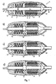
- Fig. 1a - 1d show different, variants of a work or motor handpiece.
- the motor handpiece is constructed in two parts, with a clamping system for a tool to be driven by the motor handpiece in one handpiece part and a motor in the other handpiece part.
- the motor and the clamping mechanism are mounted on one and the same shaft, which is integrally formed.
- the clamping mechanism for the tool is designed in particular as a rotary handle quick-release system, ie a tool introduced into the clamping mechanism is automatically clamped by turning the handpiece part associated with the clamping mechanism with respect to the handpiece part associated with the motor, so that the rotational movement of the motor via the integral shaft on the clamped tool can be transferred.
- a motor handpiece 1 which consists of two handpiece parts 12 and 13 which can be coupled together.
- the handpiece part 12 of the already explained above motor is arranged, which is formed in the illustrated example in the form of a brushless DC motor with an example made of laminated iron yoke ring 2, a stator winding 3 and a rotor magnet 4.
- the rotor magnet 4 may be, for example, a two-pole diametrically magnetized permanent magnet.
- the stator winding 3 and the rotor magnet 4 are formed substantially rotationally symmetrical and each have a cylindrical shape.
- the rotor magnet 4 is frictionally mounted on a drive shaft 10, so that the drive shaft 10 is driven by the rotation of the rotor magnet 4.
- the brushless DC motor is powered via a supply line 18 with power, the supply line 18 is guided through an opening in the supply line end of the motor handpiece 1 in the interior of the handpiece part 12.
- a ball bearing 14 At the supply line end of the handpiece part 12 is a ball bearing 14 to which the drive shaft 10 is rotatably mounted.
- the handpiece part 12 has at its supply line end a removable cover 22, so that the supply line end of the motor handpiece 1, the ball bearing 14 is easily accessible and accordingly can be easily replaced in case of repair.
- the second handpiece part 13 comprises the previously mentioned clamping mechanism.
- This clamping mechanism is in the embodiments shown in the drawing as Schnelleinspannmechanismus analogous to Fig. 5a built up. That is, in the examples explained below, for example, a collet 5 is provided, which can be displaced relative to the outer shell of the shaft 10 during rotation of the handpiece part 13 relative to the handpiece part 12, so that a tool 8, for example a dental tool, which is located in the collet 5, can be clamped frictionally by simply rotating the serving as a rotary handle handpiece part 13.
- Fig. 5a shows a partial cross-sectional view of this clamping mechanism shows Fig. 1 only an external view of the drive shaft 10 with the outstanding portion of the collet 5 and the spring 7.
- the spring 7 may for example be constructed as a plate or spiral helical spring and is - as already described Fig. 5a has been explained - so coupled with the collet 5 that it is compressed when pulling the collet 5 in the handpiece part 13 due to a relative rotation of the handpiece part 13 relative to the handle portion 12.
- the drive shaft 10 is rotatably mounted in the handpiece part 13 at the tool-side end by means of a ball bearing 15.
- a single-shaft system is formed with only two ball bearings 14,15 for the entire motor handpiece 1, but still a horrinspannmechanismus (Drehgriffschnellinspannmechanismus) is used.
- the in Fig. 1a illustrated brushless DC motor (without position indicator) is constructed such that the stator winding 3 fixed or pluggable the supply line 18 and the rotor magnet 4 fixed or screwed the drive shaft 10 is assigned.
- a simple division and separation of the entire engine area in the supply line 18 and the motor handle portion is possible.
- an optimal minimization of the outer dimensions and the weight of the motor handpiece is achieved with the aid of the motor handpiece according to the invention.
- a bearing change on site can be carried out easily.
- Fig. 1b shows a first embodiment of a motor handpiece according to the invention.
- the motor is housed in the handle portion 12 and the clamping mechanism in the handle portion 13, wherein the motor and the clamping mechanism are placed on one and the same shaft.
- both ball bearings 14,15 are in the handpiece part 13, which is associated with the clamping mechanism.
- the two ball bearings 14,15 are arranged at opposite end portions of the handpiece part 13, wherein the spring of the clamping mechanism between the two ball bearings 14,15 is housed.
- the drive shaft with the rotor magnet mounted thereon cantilevered into the stator winding of the DC motor and is in accordance with Fig. 1b not supported by another support bearing in the housing part 12.
- Fig. 1c and 1d show further variants of the first example.
- the motor handpiece according to Fig. 1c corresponds to the in Fig. 1b illustrated variant, but in addition a third ball bearing 16 is provided at the supply line end of the handpiece part 12.
- the handpiece part 12 in turn has a removable cover, so that the third ball bearing 16 is easily accessible from the outside.
- Fig. 1d variant shown goes to the in Fig. 1a illustrated motor handpiece back, again in each case a ball bearing 14 or 15 in the handpiece part 12 which is assigned to the electric motor, or the handpiece part 13, which is associated with the clamping mechanism, is present. While as in Fig.
- the first ball bearing 14 is accommodated on the supply line end of the handpiece part 12, now is the ball bearing 15 at that end of the handpiece 13, which is opposite to the handpiece 12. Also in Fig. 1d a removable cover 22 is provided so that the ball bearing 14 can be easily replaced.
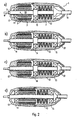
- Fig. 2a - 2d show different variants of a second example.
- This second example corresponds substantially to the first embodiment, but in contrast to Fig. 1 the chucking mechanism or the spring 7 of this chucking mechanism is accommodated in the supply line side handpiece part, while the brushless DC motor is disposed in the tool side housing part.
- Fig. 2a shows the variant that the in Fig. 1d corresponds to the variant shown.
- the handpiece part 13, in which the clamping mechanism or the spring 7 of the clamping mechanism is housed, has at its one end an opening into which the supply line 18 projects, which supplies the stator winding 3 of the brushless DC motor with electricity, if the handpiece part 12 with the handpiece part 13 has been coupled.
- the basis Fig. 5a explained actuating mechanism of the clamping system 12 and 13 causes each other due to a rotation of the two housing parts that the sleeve-shaped slotted collet 5 is pushed into the motor handle 1 and compressed accordingly, is located together with the spring 7 in the handpiece part 13.
- the clamping mechanism in turn connected to the DC motor via one and the same shaft 10, which is formed in one piece or in one piece and is rotatably supported only at two bearing points 14,15.
- the one ball bearing 14 is located at the tool-side end of the handpiece part 12, while the other ball bearing 15 is located at that end portion of the handpiece part 13, which faces the handpiece part 12.
- Fig. 2b shows a variant of in Fig. 2a shown motor handpiece, wherein the in Fig. 2b illustrated motor handpiece the in Fig. 1c shown structure, ie it is next to the ball bearings 14,15 a third ball bearing 16 for supporting the drive shaft 10 is provided.
- the arrangement of the DC motor and the clamping mechanism over the embodiments of Fig. 1 is arranged reversed, is in accordance with Fig. 2b the third ball bearing 16 on the tool-side end of the handpiece part 12.
- Fig. 2b is at the supply line side end of the handpiece part 13 which a ball bearing 15 is arranged.
- the handpiece part 13 has a removable cover 22, so that the ball bearing 15 is easily accessible and replaceable from the supply line side.
- Fig. 2c and Fig. 2d show arrangements of the second embodiment of the motor handpiece, the in Fig. 1b 1a, but again the arrangement of the DC motor and the clamping mechanism in comparison to Fig. 1 is reversed, ie the clamping mechanism is located in each of the handpiece part, which is connected to the supply line 18, during the DC motor is housed in that handpiece part in which the tool 8 is clamped.
- the two ball bearings 14 and 15 are respectively disposed in the handpiece part 13 at opposite ends thereof, so that the drive shaft projects cantilevered into the stator winding of the DC motor of the handpiece part 12.
- the two ball bearings 14 and 15 are housed at the respective outer ends of the handpiece parts 12 and 13, which leads to the greatest possible vibration stiffness of the drive shaft.
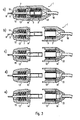
- Fig. 3a - 3e show various variants of a motor handpiece according to a third example.
- Fig. 3a - 3e variants shown substantially correspond to in Fig. 1a-1d variants shown, but according to the third example, in contrast to Fig. 1 the rotor magnet 4 is accommodated in a cavity of the drive shaft 10.
- Fig. 3a shows a first variant of the third embodiment of the present invention in the assembled state, ie in a state where the two handpiece parts 12 and 13 are screwed together while Fig. 3b the corresponding variant with exploded handpiece parts 12 and 13 represents.
- the drive shaft 10 projects cantilevered from the handpiece part 13 and is held by two ball bearings 14 and 15 in the handpiece part 13, wherein by assembling the two handpiece parts 12 and 13 that portion of the drive shaft 10 in which the rotor magnet 4 is housed, is introduced into the stator winding 3 of the brushless DC motor.
- the stator winding 3 is supplied via the supply line 18 current, whereby the non-positively accommodated within the drive shaft 10 rotor magnet 4 is set in rotation and at the same time the drive shaft 10 is driven.
- the clamping mechanism can be analogous to those in Fig. 1 . 2 and 5a be constructed motor handpieces constructed.
- Fig. 3c shows a variant, wherein the two ball bearings 14 and 15 analogous to Fig. 1a are arranged, ie there is in each case a ball bearing at the outer end of the handpiece parts 12 and 13.
- arranged on the supply line side end ball bearing 14 may be housed in the removable cover 22, so that in this case easy accessibility of the ball bearing 14 is ensured.
- Fig. 3d and 3e show further variants, wherein the arrangement of the ball bearings in Fig. 1d or 1c shown ball bearing assemblies corresponds.
- Fig. 3d as well as in Fig. 3e is the supply line side ball bearing 14 and 16 housed in the removable cover 22 of the handpiece part 12.
- Fig. 3d variant shown only two ball bearings 14, 15 are used is according to Fig. 3e the drive shaft supported by a total of three ball bearings 14, 15, 16.
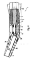
- Fig. 4 shows an example of a motor handpiece 1 with a first housing portion 23 and an angled second housing portion 24.
- first housing portion 23 of the engine 2-4 is housed, while in the second housing portion 24, any coupling mechanism 5 is provided for receiving a (dental) tool .
- this coupling mechanism can be formed analogous to the preceding embodiments by a Schnelleinspannmechanismus, wherein for example by rotation of the second housing portion 24, a tool can be automatically clamped.
- a Schnelleinspannmechanismus wherein for example by rotation of the second housing portion 24, a tool can be automatically clamped.
- this one-piece shaft 10 in the core region of the motor handpiece 1 therefore carries, on the one hand, the motor or its rotor magnet 4 and, on the other hand, the gear 26 and is in turn mounted in the motor handpiece 1 via only two ball bearings 14,15.
- motor handpiece 1 preferably has such separation points that the two ball bearings 14,15 are easily accessible when disassembling the handpiece to replace them.
- the motor handpiece 1 for dental purposes also has a channel 25 to supply a treatment site such as light, spray air or water spray.
Abstract
Description
Die vorliegende Erfindung betrifft allgemein ein Motorhandstück zum Antrieb eines mit dem Motorhandstück koppelbaren Werkzeugs. Insbesondere betrifft die vorliegende Erfindung ein Motorhandstück, welches als zahnärztliches Behandlungshandstück oder zahntechnisches Arbeitshandstück verwendet werden kann.The present invention generally relates to a motor handpiece for driving a tool coupleable to the motor handpiece. In particular, the present invention relates to a motor handpiece which can be used as a dental treatment handpiece or dental work handpiece.
Ein gattungsgemäßes Arbeitshandstück für zahntechnische Zwecke nach dem Oberbegriff des Anspruches 1 ist beispielsweise aus der
Das in
Das Schnelleinspannsystem des zweiten Handstückteils 113 umfaßt im wesentlichen eine koaxial in diesem Handstückteil angeordnete, hülsenförmig geschlitzte Spannzange 105, welche mit einer weiteren Antriebswelle 110 gekoppelt bzw. Teil desselben ist. Die Spannzange besitzt an ihrem äußeren Ende eine konische Außenform, die komplementär zu einer entsprechend ausgebildeten konischen Innenform einer Lagerhülse 106 ist, in welcher die Spannzange 105 angeordnet ist. Die Spannzange 105 ist über einen (nicht gezeigten) Betätigungsmechanismus mit dem Gehäuse des zweiten Handstückteils 113 verbunden bzw. gekoppelt. Die beiden Handstückteile 112 und 113 sind mit einander koppelbar, insbesondere verschraubbar. Bevorzugt sind die beiden Handstückteile 112 und 113 in Form eines Bajonetverschlusses miteinander verschraubbar. Der zuvor genannte Betätigungsmechanismus kann beispielsweise eine Anzugstange umfassen, welche bei Verdrehen des Gehäuses des Handstückteiles 113 gegenüber dem Gehäuse des Handstückteils 112 in eine bestimmte Richtung eine axiale Verschiebung der Spannzange 105 nach rechts hervorruft, wobei mit zunehmender Längsverschiebung der Spannzange 105 diese aufgrund der komplementär ausgebildeten Außen- bzw. Innenformen der Spannzange 105 bzw. der Lagerhülse 106 zusammengedrückt wird, so daß ein in der Spannzange 105 befindliches Werkzeug 108, von dem in
Selbstverständlich kann der zuvor erläuterte Drehgriff-Schnellspannmechanismus auch derart ausgestaltet sein, daß anstelle der Lagerhülse 106 die Spannzange 105 unbeweglich angeordnet ist, während im Gegensatz zu
Aus
Bei dem in
Aufgrund der beiden über das mechanische Mitnehmersystem 111 aneinander gekoppelten Antriebswellen 109, 110 kommt es im Laufe der Zeit zu einem verstärkten Verschleiß der beiden Antriebswellen 109, 110 im Bereich des Mitnehmersystems 111. Des weiteren treten während des Betriebs des Motorhandstücks 101 verstärkt Vibrationen auf, da aufgrund der Verwendung der beiden separaten Antriebswellen 109, 110 die Gesamtsteifigkeit der Wellenanordnung relativ gering ist. Derartige Vibrationen können jedoch beim Benutzer das sog. Weißfinger-Syndrom hervorrufen. Dabei wird bei dem Benutzer, der das Motorhandstück 101 beispielsweise im Bereich des Motorhandstückteils 113 mit seinen Fingerspitzen hält, das Blut von den Fingerspitzen weg gedrückt, wodurch die Fingerspitzen weiß werden.Due to the two
Das in
Der vorliegenden Erfindung liegt daher die Aufgabe zugrunde, ein verbessertes Arbeitshandstück zu schaffen, bei dem die zuvor beschriebenen Probleme der bekannten Arbeitshandstücke nicht auftreten.The present invention is therefore an object of the invention to provide an improved work handpiece in which the problems of the known working handpieces described above do not occur.
Insbesondere soll ein Arbeitshandstück geschaffen werden, welches die vorteile der zuvor erläuterten bekannten Arbeitshandstücke miteinander vereint, einfach handhabbar ist, montagefreundlich, fertigungsgünstig und kompakt aufgebaut ist und eine übermäßige Geräuschentwicklung auch bei hohen Drehzahlen vermeide.In particular, a work handpiece is to be created, which combines the advantages of the previously described known working handpieces together, is easy to handle, easy to install, low production and compact and avoid excessive noise even at high speeds.
Die zuvor genannten Aufgaben werden gemäß der vorliegenden Erfindung durch ein Arbeitshandstück mit den Merkmalen des unabhängigen Anspruchs 1, gelöst. Die Unteransprüche beschreiben bevorzugte und vorteilhafte Ausführungsbeispiele des erfindungsgemäßen Arbeitshandstücks.The above objects are achieved according to the present invention by a work handpiece having the features of independent claim 1. The subclaims describe preferred and advantageous embodiments of the working handpiece according to the invention.
Das erfindungsgemäße Arbeitshandstück weist wie die eingangs beschriebenen Motorhandstücke einen Motor sowie einen Einspannmechanismus zum kraftschlüssigen Einspannen eines Werkzeugs auf, wobei jedoch gemäß der vorliegenden Erfindung der Motor sowie der Einspannmechanismus auf ein und dieselbe einstückig ausgestaltete Welle aufgesetzt sind. Diese Welle muß im Prinzip nur noch mit Hilfe zweier Kugellager gelagert werden, so daß die Reibungsverluste zwischen den Lagern und der Welle sowie die Laufgeräusche reduziert werden können. Des weiteren ist die Wellensteifigkeit der Gesamtanordnung im Vergleich zu zwei miteinander gekoppelten Wellen größer und der Verschleiß der Welle geringer. Ebenso kann das erfindungsgemäße Arbeitshandstück kompakter, montagefreundlicher und fertigungsgünstiger mit geringeren Herstellungskosten aufgebaut werden. Übermäßige Vibrationen während des Betriebs des Motorhandstücks werden infolge der einstückig ausgestalteten Welle vermieden.The work handpiece according to the invention has, like the motor handpieces described above, a motor and a clamping mechanism for the frictional clamping of a tool, but according to the present invention, the motor and the clamping mechanism are placed on one and the same integrally configured shaft. This shaft must be stored in principle only with the help of two ball bearings, so that the friction losses between the bearings and the shaft and the running noise can be reduced. Furthermore, the wave rigidity of the overall arrangement is greater and the wear of the shaft is lower compared to two coupled waves. Likewise, the work handpiece according to the invention can be constructed more compact, easier to assemble and less expensive to produce with lower production costs. Excessive vibration during operation of the motor handpiece is avoided due to the integrally formed shaft.
Um auch bei hohen Drehzahlen die Verluste gering zu halten, kann der Motorwirkungsgrad minimiert werden. Der Einsatz eines Kühllüfters ist nicht erforderlich, so daß auch hierdurch keine zusätzlichen Geräusche entstehen können. Ebenso ist kein mechanisches Mitnehmersystem erforderlich, wodurch Kupplungsgeräusche vermieden werden können. Das erfindungsgemäße Arbeitshandstück erlaubt eine Kugellageranordnung, die beispielsweise im Reparaturfall einen äußerst einfachen Austausch der einzelnen Kugellager ermöglicht, da die Kugellager einfache von außen zugänglich sind. Das erfindungsgemäße Arbeitshandstück weist das eingangs beschriebene und besonders benutzerfreundliche Drehgriffschnellspannsystem auf, wobei zu diesem Zweck das Arbeitshandstück zweiteilig aufgebaut ist und durch Relativbewegung des einen Handstückteils gegenüber dem anderen Handstückteil ein Werkzeug einfach eingespannt werden kann.In order to keep the losses low even at high speeds, the engine efficiency can be minimized. The use of a cooling fan is not required, so that this also no additional noise can occur. Likewise, no mechanical entrainment system is required, whereby clutch noises can be avoided. The working handpiece according to the invention allows a ball bearing assembly, which allows, for example, in case of repair a very simple replacement of the individual ball bearings, since the ball bearings are easily accessible from the outside. The working handpiece according to the invention has the above-described and particularly user-friendly rotary handle quick release system, wherein for this purpose the working handpiece is constructed in two parts and by relative movement of a handpiece part relative to the other handpiece part a tool can be easily clamped.
Die vorliegende Erfindung wird nachfolgend anhand bevorzugter Ausführungsbeispiele unter Bezugnahme auf die beigefügte Zeichnung näher erläutert.
- Fig. 1a - 1d
- zeigen verschiedene Varianten eines ersten Ausführungsbeispiels eines Arbeitshandstücks, wobei die Varianten der
Fig. 1a, 1c und 1d nicht Gegenstand der Ansprüche sind, - Fig. 2a - 2d
- zeigen verschiedene Varianten eines zweiten Ausführungsbeispiels eines Arbeitshandstücks, welches nicht Gegenstand der Ansprüche ist,
- Fig. 3a - 3e
- zeigen verschiedene Varianten eines dritten Ausführungsbeispiels eines Arbeitshandstücks, wobei die Varianten der
Fig. 3c, 3d und 3e nicht Gegenstand der Ansprüche sind, - Fig. 4
- zeigt ein Arbeitshandstück, welches nicht Gegenstand der Ansprüche ist, und
- Fig. 5a und 5b
- zeigen bekannte Motorhandstücke.
- Fig. 1a - 1d
- show different variants of a first embodiment of a working handpiece, wherein the variants of
Fig. 1a, 1c and 1d are not the subject of the claims, - Fig. 2a - 2d
- show various variants of a second embodiment of a working handpiece, which is not the subject of the claims,
- Fig. 3a - 3e
- show different variants of a third embodiment of a working handpiece, wherein the variants of
Fig. 3c, 3d and 3e are not the subject of the claims, - Fig. 4
- shows a working handpiece, which is not the subject of the claims, and
- Fig. 5a and 5b
- show known motor handpieces.
In
Das zweite Handstückteil 13 umfaßt den bereits zuvor erwähnten Einspannmechanismus. Dieser Einspannmechanismus ist bei den in der Zeichnung dargestellten Ausführungsbeispielen als Schnelleinspannmechanismus analog zu
Wie
Der in
Die einzelnen in
Abschließend sei erwähnt, daß des Prinzip der vorliegenden Erfindung sowohl auf zahntechnische Arbeitshandstücke als auch auf zahnärztliche Behandlungshandstücke angewendet werden kann. Häufig sind jedoch zahnärztliche Behandlungshandstücke winkelig ausgestaltet, so daß die erfindungsgemäß vorgeschlagene Einstückigkeit der Welle in diesem Fall nur auf den Kernbereich eines derartigen zahnärztlichen Behandlungshandstücks zutreffen kann.Finally, it should be mentioned that the principle of the present invention can be applied both to dental work handpieces and to dental treatment handpieces. Frequently, however, dental treatment handpieces are angularly configured, so that the invention proposed integrality of the shaft in this case can apply only to the core region of such a dental treatment handpiece.
Aufgrund der winkeligen Ausgestaltung des in
Das in
Claims (5)
- A dental-technical working handpiece (1) for the operation of a tool (8) which can be coupled with the working handpiece (1) at its forward end,
having an electric motor (2-4),
having a chucking mechanism (5, 7), which has an elastic means (7) against the spring force of which the tool (8) can be clamped in the chucking mechanism (5,7) in a force-locking manner,
and having a shaft arrangement (10) in order to transfer a rotational movement of the electric motor (2-4) via the chucking mechanism (5, 7) to the clamped tool (8),
wherein the working handpiece (1) is constructed in two parts with a rearward handpiece part and a forward handpiece part that can be coupled therewith by screwing,
wherein the electric motor (2-4) is arranged in a first of the two handpiece parts, and the elastic means (7) of the chucking mechanism (5, 7), against the spring force of which the tool (8) can be clamped in the chucking mechanism (5, 7), is arranged in a second of the two handpiece parts,
wherein the chucking mechanism has a collet chuck (5), which, when one handpiece part is turned with respect to the other handpiece part, can be displaced in the longitudinal direction relative to the outer casing of the shaft (10) and against the spring force of the elastic means (7) so that a tool (8), which is located in the collet chuck, is clamped in a force-locking manner,
characterized in that
the shaft arrangement is formed by means of a shaft (10) configured in one piece, on which both the electric motor (2-4) and also the chucking mechanism (5, 7) are arranged,
the one-piece shaft (10) is mounted only at two bearing points (14, 15) of the working handpiece (1),
and one bearing point is arranged at the end of the forward handpiece part away from the rearward handpiece part,
and the other bearing point is arranged at the end of the forward handpiece part towards the rearward handpiece part,
wherein the electric motor is a collectorless d.c. motor having a stator winding (3) and a rotor magnet (4),
wherein the stator winding (3) is arranged in the first handpiece part, and wherein the rotor magnet (4) is so mounted on the one-piece shaft (10) that in the assembled condition of the working handpiece (1) the rotor magnet (4) is arranged in the stator winding (3) and a rotational movement of the rotor magnet (4) is transferred to the shaft (10). - A working handpiece according to claim 1,
characterized in that
the electric motor is supplied with current via a supply line (18) at one end of the working handpiece (1). - A working handpiece according to one of claims 1 or 2,
characterized in that
the first handpiece part is arranged at the end of the working handpiece (1) on the supply-line side, and the second handpiece part is arranged at the end of the working handpiece (1) on the tool side. - A working handpiece according to claim 2 and claim 3,
characterized in that
provided on that handpiece part which is arranged at the end of the working handpiece (1) on the supply-line side there is a removable cover (22) into which the supply line (18) is carried. - A working handpiece according to one of the previous claims,
characterized in that
each bearing point (14-16) is formed by means of a ball bearing.
Applications Claiming Priority (2)
| Application Number | Priority Date | Filing Date | Title |
|---|---|---|---|
| DE19753491 | 1997-12-02 | ||
| DE19753491A DE19753491A1 (en) | 1997-12-02 | 1997-12-02 | Motor handpiece |
Publications (4)
| Publication Number | Publication Date |
|---|---|
| EP0920839A2 EP0920839A2 (en) | 1999-06-09 |
| EP0920839A3 EP0920839A3 (en) | 2000-12-13 |
| EP0920839B1 EP0920839B1 (en) | 2006-04-26 |
| EP0920839B2 true EP0920839B2 (en) | 2012-12-19 |
Family
ID=7850525
Family Applications (1)
| Application Number | Title | Priority Date | Filing Date |
|---|---|---|---|
| EP98122300A Expired - Lifetime EP0920839B2 (en) | 1997-12-02 | 1998-11-24 | Motor handpiece |
Country Status (5)
| Country | Link |
|---|---|
| US (1) | US6126442A (en) |
| EP (1) | EP0920839B2 (en) |
| JP (1) | JP3448229B2 (en) |
| AT (1) | ATE324078T1 (en) |
| DE (2) | DE19753491A1 (en) |
Families Citing this family (13)
| Publication number | Priority date | Publication date | Assignee | Title |
|---|---|---|---|---|
| DE10161945A1 (en) * | 2001-12-17 | 2003-07-17 | W & H Dentalwerk Buermoos Ges | Brushless electric motor and instrument for a medical device with such a motor |
| AT5535U1 (en) * | 2002-04-24 | 2002-08-26 | W & H Dentalwerk Buermoos Gmbh | MOTOR HANDPIECE |
| WO2005089666A1 (en) * | 2004-02-17 | 2005-09-29 | Bien-Air Holding S.A. | Handpiece for dental or surgical use with locking mechanism |
| US20050181326A1 (en) * | 2004-02-17 | 2005-08-18 | Bien-Air Holding S.A. | Powered handpiece for dental or surgical use |
| DE102006051510A1 (en) * | 2006-03-09 | 2007-09-13 | Kaltenbach & Voigt Gmbh | Dental, dental or dental technical handpiece with electric motor |
| DE102006013455B3 (en) * | 2006-03-23 | 2007-07-12 | Gebr. Brasseler Gmbh & Co. Kg | Dental tool holder comprises semi-cylindrical shell with guide ring at its base, into which tool shaft fits, similar half-shell, hinged e.g. at top, locking tool in place and rib on its inner surface fitting into peripheral groove on shaft |
| JP4912752B2 (en) * | 2006-05-30 | 2012-04-11 | 日本電産テクノモータホールディングス株式会社 | motor |
| DE102007014691A1 (en) * | 2007-03-27 | 2008-10-02 | Kaltenbach & Voigt Gmbh | Electric motor for use in a dental, dental or dental handpiece and stator therefor |
| KR101059742B1 (en) | 2009-12-31 | 2011-09-01 | (주)마이크로엔엑스 | Handpiece motor |
| FR3016283B1 (en) * | 2014-01-13 | 2016-01-15 | Guy Charles Levy | TRAINING FOR AGAINST ANGLE IN DENTISTRY |
| KR101653543B1 (en) * | 2014-12-30 | 2016-09-02 | 이종건 | Handpiece of high-speed rotation capable having low-vibration structure |
| KR101663983B1 (en) * | 2014-12-30 | 2016-10-11 | 이종건 | Slim handpiece of having light emitting means |
| DE102019102179A1 (en) * | 2019-01-29 | 2020-07-30 | NWT Management GmbH | Handpiece for a medical or cosmetic processing device |
Citations (11)
| Publication number | Priority date | Publication date | Assignee | Title |
|---|---|---|---|---|
| US3109238A (en) † | 1961-11-28 | 1963-11-05 | Samuel B Marks | Portable dental drill |
| US3672060A (en) † | 1968-07-24 | 1972-06-27 | Kaltenbach & Voigt | Dental instrument |
| DE2253880A1 (en) † | 1971-11-09 | 1973-05-24 | Morita Mfg | MICROMOTOR FOR DENTAL INSTRUMENTS |
| US3928701A (en) † | 1974-07-16 | 1975-12-23 | Soll Roehner | Helix of a series of discarded vehicle tires |
| DE2756011A1 (en) † | 1977-05-31 | 1978-12-14 | Arnegger Richard E | HAND TOOL |
| EP0012871A2 (en) † | 1978-12-22 | 1980-07-09 | Siemens Aktiengesellschaft | Dental handpiece assembly |
| CH649876A5 (en) † | 1978-12-07 | 1985-06-14 | Sven Karl Lennart Goof | ELECTRIC MOTOR WITH ADJUSTABLE SPEED. |
| JPS61139208A (en) † | 1984-12-06 | 1986-06-26 | 東芝プラント建設株式会社 | Cable housing unit for cable extention |
| FR2575060A1 (en) † | 1984-12-20 | 1986-06-27 | Medizin Labortechnik Veb K | Electrical drive for dental instrument |
| DE4406855A1 (en) † | 1994-03-02 | 1995-09-07 | Kaltenbach & Voigt | Straight motor handpiece, especially for medical purposes, preferably for a medical or dental laboratory |
| DE19644491A1 (en) † | 1996-10-25 | 1998-04-30 | Kaltenbach & Voigt | Dental handpiece |
Family Cites Families (6)
| Publication number | Priority date | Publication date | Assignee | Title |
|---|---|---|---|---|
| US2660441A (en) * | 1951-07-12 | 1953-11-24 | Magnus E Toelcke | Collet chuck |
| US3978586A (en) * | 1975-02-10 | 1976-09-07 | The Denticator Company, Inc. | Dental apparatus |
| US4183140A (en) * | 1977-05-31 | 1980-01-15 | Concept Inc. | Dental stain remover |
| US4184256A (en) * | 1977-12-12 | 1980-01-22 | Kaltenbach & Voigt Gmbh & Co. | Miniature motor having an internal coolant line |
| JPS5656314U (en) * | 1979-10-08 | 1981-05-15 | ||
| JPH0737606Y2 (en) * | 1993-08-20 | 1995-08-30 | 株式会社中西歯科器械製作所 | Dental handpiece |
-
1997
- 1997-12-02 DE DE19753491A patent/DE19753491A1/en not_active Withdrawn
-
1998
- 1998-11-23 US US09/197,710 patent/US6126442A/en not_active Expired - Lifetime
- 1998-11-24 DE DE59813513T patent/DE59813513D1/en not_active Expired - Lifetime
- 1998-11-24 AT AT98122300T patent/ATE324078T1/en active
- 1998-11-24 EP EP98122300A patent/EP0920839B2/en not_active Expired - Lifetime
- 1998-11-30 JP JP33991498A patent/JP3448229B2/en not_active Expired - Lifetime
Patent Citations (13)
| Publication number | Priority date | Publication date | Assignee | Title |
|---|---|---|---|---|
| US3109238A (en) † | 1961-11-28 | 1963-11-05 | Samuel B Marks | Portable dental drill |
| US3672060A (en) † | 1968-07-24 | 1972-06-27 | Kaltenbach & Voigt | Dental instrument |
| DE2253880A1 (en) † | 1971-11-09 | 1973-05-24 | Morita Mfg | MICROMOTOR FOR DENTAL INSTRUMENTS |
| US3928701A (en) † | 1974-07-16 | 1975-12-23 | Soll Roehner | Helix of a series of discarded vehicle tires |
| DE2756011A1 (en) † | 1977-05-31 | 1978-12-14 | Arnegger Richard E | HAND TOOL |
| CH649876A5 (en) † | 1978-12-07 | 1985-06-14 | Sven Karl Lennart Goof | ELECTRIC MOTOR WITH ADJUSTABLE SPEED. |
| EP0012871A2 (en) † | 1978-12-22 | 1980-07-09 | Siemens Aktiengesellschaft | Dental handpiece assembly |
| JPS61139208A (en) † | 1984-12-06 | 1986-06-26 | 東芝プラント建設株式会社 | Cable housing unit for cable extention |
| FR2575060A1 (en) † | 1984-12-20 | 1986-06-27 | Medizin Labortechnik Veb K | Electrical drive for dental instrument |
| DE3527796A1 (en) † | 1984-12-20 | 1986-07-03 | Veb Kombinat Medizin- Und Labortechnik Leipzig, Ddr 7033 Leipzig | Electrical drive system for a dental handpiece |
| DE4406855A1 (en) † | 1994-03-02 | 1995-09-07 | Kaltenbach & Voigt | Straight motor handpiece, especially for medical purposes, preferably for a medical or dental laboratory |
| DE19644491A1 (en) † | 1996-10-25 | 1998-04-30 | Kaltenbach & Voigt | Dental handpiece |
| WO1998018401A1 (en) † | 1996-10-25 | 1998-05-07 | Kaltenbach & Voigt Gmbh & Co. | Dental tool holder |
Non-Patent Citations (2)
| Title |
|---|
| Prospekt "Was sie schon immer suchten", Bewährte SF-Motorentechnik, Praezident 1995 † |
| Technikeranweisung KaVo Elektrionisches Werk GmbH, SF Handstück, 1.März 1981 † |
Also Published As
| Publication number | Publication date |
|---|---|
| EP0920839A2 (en) | 1999-06-09 |
| EP0920839A3 (en) | 2000-12-13 |
| ATE324078T1 (en) | 2006-05-15 |
| JP3448229B2 (en) | 2003-09-22 |
| EP0920839B1 (en) | 2006-04-26 |
| DE19753491A1 (en) | 1999-06-10 |
| JPH11221232A (en) | 1999-08-17 |
| DE59813513D1 (en) | 2006-06-01 |
| US6126442A (en) | 2000-10-03 |
Similar Documents
| Publication | Publication Date | Title |
|---|---|---|
| EP1993463B1 (en) | Handpiece for dentists, dental surgeons, or dental technicians, comprising an electric motor | |
| EP0920839B2 (en) | Motor handpiece | |
| EP0408987B1 (en) | Electric tool | |
| DE2855719C2 (en) | ||
| EP0491894B1 (en) | Main-spindle drive for a machine toole | |
| EP0888091B1 (en) | Dental tool holder | |
| EP0408986A2 (en) | Switch device for electrical change-over switching of electric tools | |
| EP0563583A1 (en) | Motor drive, especially electro-motor drive for window or slide-roof | |
| DE10033577A1 (en) | Small brushless motor e.g. for rotating medical cutting or grinding instrument, comprises rear support for covering rear opening of outer housing and conducting connections penetrating outwards from rear side of coil unit | |
| EP0008049B1 (en) | Dc micromotor for driving a dental tool | |
| DE3309249A1 (en) | DEVICE FOR SLIDING A SLIDE OR THE LIKE. ON A BED OR THE LIKE. | |
| DE102005025352B4 (en) | Outer vortex device with a vortex unit | |
| DE3142740C2 (en) | ||
| EP1199500B1 (en) | Shift actuator of a gearbox | |
| EP1048401B1 (en) | Tool change apparatus | |
| DE102006054267A1 (en) | Hand tool with brushless motor | |
| DE3145217A1 (en) | Linear drive unit | |
| DE19833794A1 (en) | Hand-held power tool, especially jigsaw | |
| DE19960350A1 (en) | Tool drive for machine tools | |
| EP1923173A1 (en) | Manual tool machine | |
| DE3915526A1 (en) | Duplex-form electric motor or generator - has hollow rotor with internal stator coil and external stator coil | |
| DE102019203180A1 (en) | Brushless DC motor of a hand machine tool | |
| DE7638512U1 (en) | PUSH AND PULL DRIVE | |
| EP1362559B1 (en) | Motor handpiece | |
| DE102004049630A1 (en) | Pressurized-water cleaning device, uses slip-ring free electrical machine as drive |
Legal Events
| Date | Code | Title | Description |
|---|---|---|---|
| PUAI | Public reference made under article 153(3) epc to a published international application that has entered the european phase |
Free format text: ORIGINAL CODE: 0009012 |
|
| AK | Designated contracting states |
Kind code of ref document: A2 Designated state(s): AT CH DE FR IT LI |
|
| AX | Request for extension of the european patent |
Free format text: AL;LT;LV;MK;RO;SI |
|
| PUAL | Search report despatched |
Free format text: ORIGINAL CODE: 0009013 |
|
| AK | Designated contracting states |
Kind code of ref document: A3 Designated state(s): AT BE CH CY DE DK ES FI FR GB GR IE IT LI LU MC NL PT SE |
|
| AX | Request for extension of the european patent |
Free format text: AL;LT;LV;MK;RO;SI |
|
| RIC1 | Information provided on ipc code assigned before grant |
Free format text: 7A 61C 1/08 A, 7A 61C 1/06 B, 7A 61C 1/18 B |
|
| 17P | Request for examination filed |
Effective date: 20010411 |
|
| AKX | Designation fees paid |
Free format text: AT CH DE FR IT LI |
|
| RAP1 | Party data changed (applicant data changed or rights of an application transferred) |
Owner name: KALTENBACH & VOIGT GMBH & CO. KG |
|
| 17Q | First examination report despatched |
Effective date: 20040812 |
|
| GRAP | Despatch of communication of intention to grant a patent |
Free format text: ORIGINAL CODE: EPIDOSNIGR1 |
|
| GRAS | Grant fee paid |
Free format text: ORIGINAL CODE: EPIDOSNIGR3 |
|
| GRAA | (expected) grant |
Free format text: ORIGINAL CODE: 0009210 |
|
| AK | Designated contracting states |
Kind code of ref document: B1 Designated state(s): AT CH DE FR IT LI |
|
| PG25 | Lapsed in a contracting state [announced via postgrant information from national office to epo] |
Ref country code: IT Free format text: LAPSE BECAUSE OF FAILURE TO SUBMIT A TRANSLATION OF THE DESCRIPTION OR TO PAY THE FEE WITHIN THE PRESCRIBED TIME-LIMIT;WARNING: LAPSES OF ITALIAN PATENTS WITH EFFECTIVE DATE BEFORE 2007 MAY HAVE OCCURRED AT ANY TIME BEFORE 2007. THE CORRECT EFFECTIVE DATE MAY BE DIFFERENT FROM THE ONE RECORDED. Effective date: 20060426 |
|
| RAP1 | Party data changed (applicant data changed or rights of an application transferred) |
Owner name: KALTENBACH & VOIGT GMBH |
|
| REF | Corresponds to: |
Ref document number: 59813513 Country of ref document: DE Date of ref document: 20060601 Kind code of ref document: P |
|
| REG | Reference to a national code |
Ref country code: CH Ref legal event code: NV Representative=s name: A. BRAUN, BRAUN, HERITIER, ESCHMANN AG PATENTANWAE |
|
| ET | Fr: translation filed | ||
| PLAX | Notice of opposition and request to file observation + time limit sent |
Free format text: ORIGINAL CODE: EPIDOSNOBS2 |
|
| PLBI | Opposition filed |
Free format text: ORIGINAL CODE: 0009260 |
|
| 26 | Opposition filed |
Opponent name: W&H DENTALWERK BUERMOOS GMBH Effective date: 20070126 |
|
| PLAF | Information modified related to communication of a notice of opposition and request to file observations + time limit |
Free format text: ORIGINAL CODE: EPIDOSCOBS2 |
|
| PLBB | Reply of patent proprietor to notice(s) of opposition received |
Free format text: ORIGINAL CODE: EPIDOSNOBS3 |
|
| REG | Reference to a national code |
Ref country code: CH Ref legal event code: PFA Owner name: KALTENBACH & VOIGT GMBH Free format text: KALTENBACH & VOIGT GMBH#BISMARCKRING 39#88400 BIBERACH / RISS (DE) -TRANSFER TO- KALTENBACH & VOIGT GMBH#BISMARCKRING 39#88400 BIBERACH / RISS (DE) |
|
| PLAY | Examination report in opposition despatched + time limit |
Free format text: ORIGINAL CODE: EPIDOSNORE2 |
|
| PLAB | Opposition data, opponent's data or that of the opponent's representative modified |
Free format text: ORIGINAL CODE: 0009299OPPO |
|
| PLBC | Reply to examination report in opposition received |
Free format text: ORIGINAL CODE: EPIDOSNORE3 |
|
| APBM | Appeal reference recorded |
Free format text: ORIGINAL CODE: EPIDOSNREFNO |
|
| APBP | Date of receipt of notice of appeal recorded |
Free format text: ORIGINAL CODE: EPIDOSNNOA2O |
|
| APAH | Appeal reference modified |
Free format text: ORIGINAL CODE: EPIDOSCREFNO |
|
| APBQ | Date of receipt of statement of grounds of appeal recorded |
Free format text: ORIGINAL CODE: EPIDOSNNOA3O |
|
| APAH | Appeal reference modified |
Free format text: ORIGINAL CODE: EPIDOSCREFNO |
|
| APBU | Appeal procedure closed |
Free format text: ORIGINAL CODE: EPIDOSNNOA9O |
|
| PUAH | Patent maintained in amended form |
Free format text: ORIGINAL CODE: 0009272 |
|
| STAA | Information on the status of an ep patent application or granted ep patent |
Free format text: STATUS: PATENT MAINTAINED AS AMENDED |
|
| 27A | Patent maintained in amended form |
Effective date: 20121219 |
|
| AK | Designated contracting states |
Kind code of ref document: B2 Designated state(s): AT CH DE FR IT LI |
|
| REG | Reference to a national code |
Ref country code: CH Ref legal event code: AELC |
|
| REG | Reference to a national code |
Ref country code: DE Ref legal event code: R102 Ref document number: 59813513 Country of ref document: DE Effective date: 20121219 |
|
| REG | Reference to a national code |
Ref country code: CH Ref legal event code: PCAR Free format text: NEW ADDRESS: HOLBEINSTRASSE 36-38, 4051 BASEL (CH) |
|
| REG | Reference to a national code |
Ref country code: FR Ref legal event code: PLFP Year of fee payment: 18 |
|
| REG | Reference to a national code |
Ref country code: FR Ref legal event code: PLFP Year of fee payment: 19 |
|
| REG | Reference to a national code |
Ref country code: FR Ref legal event code: PLFP Year of fee payment: 20 |
|
| PGFP | Annual fee paid to national office [announced via postgrant information from national office to epo] |
Ref country code: FR Payment date: 20171124 Year of fee payment: 20 Ref country code: DE Payment date: 20171207 Year of fee payment: 20 |
|
| PGFP | Annual fee paid to national office [announced via postgrant information from national office to epo] |
Ref country code: AT Payment date: 20171122 Year of fee payment: 20 Ref country code: CH Payment date: 20171123 Year of fee payment: 20 Ref country code: IT Payment date: 20171130 Year of fee payment: 20 |
|
| REG | Reference to a national code |
Ref country code: DE Ref legal event code: R071 Ref document number: 59813513 Country of ref document: DE |
|
| REG | Reference to a national code |
Ref country code: CH Ref legal event code: PL |
|
| REG | Reference to a national code |
Ref country code: AT Ref legal event code: MK07 Ref document number: 324078 Country of ref document: AT Kind code of ref document: T Effective date: 20181124 |