EP0920239A2 - Anchoring means for implantable microphone - Google Patents
Anchoring means for implantable microphone Download PDFInfo
- Publication number
- EP0920239A2 EP0920239A2 EP98100918A EP98100918A EP0920239A2 EP 0920239 A2 EP0920239 A2 EP 0920239A2 EP 98100918 A EP98100918 A EP 98100918A EP 98100918 A EP98100918 A EP 98100918A EP 0920239 A2 EP0920239 A2 EP 0920239A2
- Authority
- EP
- European Patent Office
- Prior art keywords
- fixation element
- element according
- ear canal
- flange parts
- wall
- Prior art date
- Legal status (The legal status is an assumption and is not a legal conclusion. Google has not performed a legal analysis and makes no representation as to the accuracy of the status listed.)
- Granted
Links
Images


Classifications
-
- A—HUMAN NECESSITIES
- A61—MEDICAL OR VETERINARY SCIENCE; HYGIENE
- A61F—FILTERS IMPLANTABLE INTO BLOOD VESSELS; PROSTHESES; DEVICES PROVIDING PATENCY TO, OR PREVENTING COLLAPSING OF, TUBULAR STRUCTURES OF THE BODY, e.g. STENTS; ORTHOPAEDIC, NURSING OR CONTRACEPTIVE DEVICES; FOMENTATION; TREATMENT OR PROTECTION OF EYES OR EARS; BANDAGES, DRESSINGS OR ABSORBENT PADS; FIRST-AID KITS
- A61F2/00—Filters implantable into blood vessels; Prostheses, i.e. artificial substitutes or replacements for parts of the body; Appliances for connecting them with the body; Devices providing patency to, or preventing collapsing of, tubular structures of the body, e.g. stents
- A61F2/02—Prostheses implantable into the body
- A61F2/18—Internal ear or nose parts, e.g. ear-drums
- A61F2002/183—Ear parts
-
- H—ELECTRICITY
- H04—ELECTRIC COMMUNICATION TECHNIQUE
- H04R—LOUDSPEAKERS, MICROPHONES, GRAMOPHONE PICK-UPS OR LIKE ACOUSTIC ELECTROMECHANICAL TRANSDUCERS; DEAF-AID SETS; PUBLIC ADDRESS SYSTEMS
- H04R25/00—Deaf-aid sets, i.e. electro-acoustic or electro-mechanical hearing aids; Electric tinnitus maskers providing an auditory perception
- H04R25/60—Mounting or interconnection of hearing aid parts, e.g. inside tips, housings or to ossicles
- H04R25/604—Mounting or interconnection of hearing aid parts, e.g. inside tips, housings or to ossicles of acoustic or vibrational transducers
- H04R25/606—Mounting or interconnection of hearing aid parts, e.g. inside tips, housings or to ossicles of acoustic or vibrational transducers acting directly on the eardrum, the ossicles or the skull, e.g. mastoid, tooth, maxillary or mandibular bone, or mechanically stimulating the cochlea, e.g. at the oval window
Definitions
- the invention relates to a fixation element for an implantable microphone a cylindrical housing part provided with a sound inlet membrane in a bore crossing the rear bony wall of the auditory canal can be used and that form part of a partially or fully implantable hearing aid, for example can.
- the invention has for its object a fixation element of the aforementioned Art to create that a much simplified and yet highly precise implantation of the microphone while avoiding the use of bone cement associated disadvantages allowed.
- a fixation element for an implantable microphone with a cylindrical housing part provided with a sound inlet membrane in a hole crossing the rear bony auditory canal wall can be used, solved, which is characterized according to the invention by a cuff with a cylindrical sleeve part encloses the cylindrical housing part and the projecting against the side of the ear canal wall facing the ear canal skin has elastic flange parts.
- the fixation element according to the invention allows the microphone housing in the Easy to clip in the hole through the auditory canal wall.
- the stake of bone cement is avoided.
- Those that lie against the bony wall of the auditory canal Flange parts ensure an exact alignment of the microphone housing Regarding the ear canal wall. Together with that engages with the bore wall standing cylindrical sleeve part they provide a safe and long-term stable Hold the implanted microphone securely.
- the cuff is projecting with further Provide flange parts that against the side facing away from the ear canal skin bony ear canal wall can be created. This will hold the microphone in place implanted condition further improved. Furthermore, an unintentional tilting of the Microphone housing opposite the ear canal wall during the implantation process or reliably excluded later.
- the entire cuff is preferably made of biocompatible elastic material manufactured, which suitably from the group consisting of silicones and polyurethanes is selected.
- biocompatible elastic material manufactured, which suitably from the group consisting of silicones and polyurethanes is selected.
- Such a material allows a limited deformation of the sleeve when inserted into the bore of the bony ear canal wall. It enables it the flange parts, against the relevant side of the ear canal wall properly to create. In the area of the cylindrical sleeve part can easily for a clamping force can be provided.
- the sleeve can be part of a casing be the microphone with the exception of the sound inlet membrane at least larger part and preferably completely encloses. This makes it a particularly safe one
- the cuff is anchored with respect to the microphone housing.
- the flange parts which, when implanted, oppose those of the ear canal skin facing side of the ear canal wall can be placed during implantation using a tool to hold it in a position in which it can pass through the hole in the Ear canal wall can be inserted.
- Implanting the microphone but is particularly simple if, in a further development of the invention, a holder It is provided which the against the side of the ear canal skin facing Earpiece wall attachable flange parts before implantation against an elastic Restoring force of the flange parts in a pushing through the bore of the Ear canal wall allowing bent position.
- a thread that can be severed during the implantation is provided be that of the associated flange parts in a way that does not interfere with the implantation Holds position and then the relevant flange parts due to their elastic Properties pass into a relaxed position in which they hold their function take.
- a cap attached to the bent flange parts be.
- those against the ear canal skin facing flange side facing the ear canal wall inclined from the cylindrical sleeve part towards this sleeve part. This contributes to the correct application of the flange parts to those of the ear canal skin facing side of the ear canal wall, even if the surface in question
- the auditory canal wall has certain bumps due to the anatomical conditions having.
- the wall thickness preferably increases against that flange parts that can be placed on the side of the ear canal wall facing the ear canal skin radially outwards.
- the side of the auditory canal wall facing the ear canal skin Flange parts can be in particular in the relaxed state starting from the cylindrical sleeve part formed essentially radially projecting ring flange be. Basically, however, other geometric configurations also come into play Consider if only the required holding function is guaranteed on the one hand and on the other hand, the flange parts in the space between the ear canal skin and the ear canal wall easily find space.
- the side of the auditory canal wall facing the auditory canal skin attachable flange parts with openings in particular have the task of a nutrient transfer between the bony ear canal wall and to enable the ear canal skin in the area of the ring flange.
- fixation element according to the invention is basically for microphones any shape, for example also for microphones with a continuous cylindrical Housing, is suitable. However, if the microphone is used in a manner known per se (essay "An implantable microphone for electronic hearing implants" by H.
- a first housing leg forms the cylindrical housing part and a second housing leg about the thickness of the rear bony Corresponding distance of the ear canal wall to the plane of the sound entry membrane is set back, advantageously forms the second housing leg itself or at least part of the fixation element encasing the second housing leg a part of the flange parts against the side facing away from the ear canal skin the ear canal wall can be put on.
- One of the flange parts is against the side of the auditory canal wall facing away from the auditory canal skin can be applied, preferably a shoulder that is diametrically opposite to the second housing leg Protrudes from the cylindrical sleeve part.
- At least the sleeve made of a material with a Shore A hardness is expedient manufactured from 20 to 70.
- FIG. 1 schematically shows a microphone 10 that is part of a partially or fully implantable Hearing aid can be.
- the hearing aid as such can be used in a manner known per se be trained. Examples of such hearing aids are in the article "Active electronic Hearing implants for middle and inner ear deaf people - a new era in ear surgery " by H. P. Zenner et al., HNO 45: 749-757 (October 1997).
- the microphone 10 has a two-leg microphone housing 11, which is shown in FIG. 1 for simplification the representation only indicated schematically and therefore not illustrated in section is.
- a microphone capsule is located in a first leg 12 of the microphone housing 11 housed, and the leg 12 forms one with a sound entry membrane 13 provided cylindrical housing part 14.
- a second housing leg 15 takes an electrical bushing indicated schematically at 16 for an electrical one Lead 17 on.
- the microphone 10 is equipped with a fixation element 20 which, in the exemplary embodiment illustrated, forms a sheath which receives the entire microphone.
- a fixation element 20 which, in the exemplary embodiment illustrated, forms a sheath which receives the entire microphone.
- the collar 21 also includes flange parts 23, 24 and 25 which project radially outwards at both axial ends of the cylindrical collar part 22.
- the cylindrical housing part 14 together with the cylindrical sleeve part 22 can be inserted from a mastoid cavity 27 into a bore 28 which crosses a rear bony auditory canal wall 29.
- FIG. 1 the cylindrical housing part 14 together with the cylindrical sleeve part 22 can be inserted from a mastoid cavity 27 into a bore 28 which crosses a rear bony auditory canal wall 29.
- the ear canal lined with ear canal skin 30 and the eardrum at 32 are indicated.
- the dimensioning is chosen so that in the implanted state of the microphone 10, the flange parts 23, 24 and 25 on the one hand lie against the side 33 facing the auditory canal skin 30 and on the other hand against the side 34 of the auditory canal wall 29 facing away from the auditory canal skin and thereby the sound entry membrane 13 in direct mechanical contact with the auditory canal skin 30 comes.
- the axial distance a between the flange part 23 and the flange parts 24 and 25 is dimensioned such that it corresponds to the average wall thickness of the bony ear canal wall 29.
- the distance a is generally in the range from 1.0 to 2.5 mm. It is preferably about 1.6 mm.
- the sound entry membrane 13 preferably has a diameter of less than 5.0 mm.
- the cylindrical housing part 14 accordingly has an outer diameter of approximately 4.5 mm and the cylindrical sleeve part 22 has an outer diameter of approximately 5.3 mm.
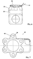
- the ring flange 23 is with a series of openings arranged distributed in the circumferential direction 36 provided.
- the main purpose of the openings 36 is to transport nutrients between the bony ear canal wall 29 and the ear canal skin 30 in the area of the ring flange 23. Shape and number of openings 36 are immaterial as long as the breakthroughs serve this purpose and the necessary ones mechanical strength of the ring flange 23 is maintained.
- the openings 36 make a surgical one Thread 37 and threaded in, for example, by twisting, knotting or the like a state temporarily fixed, in which the ring flange 23 according to FIG. 6 in axially folded away from the flange parts 24 and 25 and contracted is.
- the one surrounded by the cylindrical sleeve part 22 can be used Insert the cylindrical housing part 14 through the bore 28 in the auditory canal wall 30. If the thread 37 is then severed, the ring flange 23 returns to it relaxed form according to Figures 1 to 4 back. To such behavior force is at least the part of the fixation element forming the annular flange 23 20 elastic.
- the ring flange 23 In the implanted state (FIG. 1), the ring flange 23 should contact the ear canal skin 30 facing side 33 of the auditory canal wall 30 regardless of unevenness cling to this wall surface as closely as possible.
- the wall thickness of the ring flange 23 is reduced as much as this is possible without impairing the holding function of the ring flange.
- the annular flange 23 starting from the cylindrical sleeve part 22 in Direction towards the flange parts 24, 25 inclined.
- the wall thickness of the Ring flange 23 radially outwards.
- the wall thickness of the ring flange 23 can Appropriately from about 0.1 to 0.2 mm near the cuff part 22 to about 0.03 to 0.1 mm on the outer edge of the ring flange 23 may be reduced.
- the angle of inclination ⁇ des Ring flange 23 can range from 0 to 20 degrees, preferably about 5 degrees, lie.
- the flange part 25 is formed by the part of the casing (fixation element 20), which covers the side of the housing leg 15 facing the ring flange 23.
- the flange part 24 is a shoulder on the housing leg 15 diametrically opposite side of the cylindrical sleeve part 22 protrudes (see in particular Figures 3 and 4).
- the fixation element 20 Care during the implantation of the microphone 10 encased with the fixation element 20 the flange parts 23, 24 and 25 for an alignment of the sound inlet membrane 13 and the housing leg 15 parallel to the bony ear canal wall 29 in one Position in which the sound entry membrane 13 is substantially flush with that of the Ear canal skin 30 facing side 33 of the auditory canal wall 29.
- the fixation element 20 holds the microphone securely at the implantation site, without additional measures or means, for example bone cement, become necessary. If necessary, the microphone can be after inserting the cylindrical sleeve part 22 into the bore 28 to the in FIG. 4 Turn the axis of the cylindrical housing part 14 indicated at 40.
- the fixation element 20 is expediently a receiving the microphone housing 11 Molded part.
- a biocompatible material is particularly suitable as the material for the fixation element 20 Plastic with a Shore A hardness of 20 to 70. This can happen are all about silicones or polyurethanes.
- the modified embodiment of the fixation element 42 according to FIG. 7 differs from the previously explained fixation element 20 essentially only by that in the implanted state between the ear canal wall 29 and the ear canal skin 30 lying flange parts not from an annular flange 23, but from one Sequence of flange segments distributed in the circumferential direction of the cylindrical sleeve part 43 are formed.
- the flange segments 43 can, as shown, be provided with openings 36. Such breakthroughs can also can be dispensed with, especially if one is due to the shape of the flange parts Nutrient transport between the ear canal wall 29 and the ear canal skin 30 is ensured is.
- FIG. 8 shows a further modified embodiment, designated 46 overall of the fixation element, which is suitable for microphones with one-leg, cylindrical Microphone housing is suitable.
- the fixation element 46 in turn has a sleeve 48 on that with a cylindrical sleeve part 49 a cylindrical part of the Microphone housing encloses and which against the in FIG. 1 shown, the ear canal skin 30 facing page 33 and page 34 facing away from the ear canal skin projecting flange parts 50 and 51, respectively, of the auditory canal wall 29 having.
- the flange part 50 can in particular correspond to the flange ring 23 Figures 2 to 6 designed or of flange segments 43 of FIG. 7 be formed.
- the flange part 51 can expediently be designed as an annular shoulder.
- FIG. 9 shows a view similar to FIG. 6, but instead of the thread 37 a Cap 53 for retaining those that can be placed against the side 33 of the auditory canal wall 29 Flange parts 23, 43 and 50 are provided before and during the implantation is.
- the cap 53 is so thin-walled at least in the region of its hollow cylindrical part 54 executed that they together with the cylindrical sleeve part 22 and 49 inserted into the bore 28 and then with the release of the flange parts 23, 43 or 50 can be removed from the ear canal 31.
- the Cap a nipple 55 on its closed side.
- the cap 53 is expediently a relatively stiff and hard plate 56 is used.
- the cap part 54 is preferably elastically extensible to a limited extent.
- the cap material must be sterilizable; otherwise comes a variety of materials, especially Metals and plastics.
- the cap 53 provides, especially if it equipped with plate 56 before implantation for excellent protection the sound entry membrane 13.
Abstract
Description
Die Erfindung betrifft ein Fixationselement für ein implantierbares Mikrofon, das mit einem mit einer Schalleintrittsmembran versehenen zylinderförmigen Gehäuseteil in eine die hintere knöcherne Gehörgangswand durchquerende Bohrung einsetzbar ist und das beispielsweise einen Bestandteil einer teil- oder vollimplantierbaren Hörhilfe bilden kann.The invention relates to a fixation element for an implantable microphone a cylindrical housing part provided with a sound inlet membrane in a bore crossing the rear bony wall of the auditory canal can be used and that form part of a partially or fully implantable hearing aid, for example can.
Ein Ausführungsbeispiel eines Mikrofons der vorstehend genannten Art ist Gegenstand der früheren EP-Patentanmeldung 97 114 603 und in dem Aufsatz "Ein implantierbares Mikrofon für elektronische Hörimplantate" von H. Leysieffer et al., HNO 45: 816-827 (Oktober 1997) näher erläutert. Aus dem genannten Aufsatz ist es bekannt, das Mikrofongehäuse im Mastoid mittels Knochenzement mechanisch zu fixieren. Eine Zementfixierung ist jedoch mit zahlreichen Problemen behaftet. So kann der Knochenzement unter Umständen am Implantationsort unerwünschte Nebeneffekte auslösen. Die Handhabung ist angesichts der beengten Platzverhältnisse und der ungünstigen Sichtbedingungen am Implantationsort schwierig. Knochenzement kann unerwünscht auch an Stellen gelangen, wo er stört. Eine nachträgliche Korrektur der Mikrofonposition in der Bohrung der Gehörgangswand ist praktisch ausgeschlossen. Es wäre denkbar, das Mikrofongehäuse in die Bohrung der Gehörgangswand einzuschrauben. Klinische Experimente zeigen jedoch, daß dies wegen der geringen Dicke der knöchernen Gehörgangswand problematisch ist. Außerdem werden Schrauben im Bereich dieser Implantationsstelle häufig auch noch lange Zeit nach dem chirurgischen Eingriff schmerzhaft wahrgenommen.An embodiment of a microphone of the type mentioned above is the subject the earlier EP patent application 97 114 603 and in the article "An implantable Microphone for electronic hearing implants "by H. Leysieffer et al., HNO 45: 816-827 (October 1997) explained in more detail. From the above article it is known the microphone housing mechanically fixed in the mastoid using bone cement. A cement fixation is fraught with numerous problems. So can the bone cement may trigger undesirable side effects at the implantation site. The handling is given the limited space and the unfavorable visibility difficult at the implantation site. Bone cement can also be undesirable Get places where it bothers. A subsequent correction of the microphone position in the Drilling the ear canal wall is practically impossible. It would be conceivable that Screw the microphone housing into the hole in the ear canal wall. Clinical However, experiments show that this is due to the small thickness of the bony ear canal wall is problematic. There are also screws in the area of this implantation site often painful for a long time after the surgery perceived.
Der Erfindung liegt die Aufgabe zugrunde, ein Fixationselement der eingangs genannten Art zu schaffen, das eine wesentlich vereinfachte und gleichwohl hoch präzise Implantation des Mikrofons unter Vermeidung der mit dem Einsatz von Knochenzement verbundenen Nachteile gestattet.The invention has for its object a fixation element of the aforementioned Art to create that a much simplified and yet highly precise implantation of the microphone while avoiding the use of bone cement associated disadvantages allowed.
Diese Aufgabe wird mit einem Fixationselement für ein implantierbares Mikrofon, das mit einem mit einer Schalleintrittsmembran versehenen zylinderförmigen Gehäuseteil in eine die hintere knöcherne Gehörgangswand durchquerende Bohrung einsetzbar ist, gelöst, das erfindungsgemäß durch eine Manschette gekennzeichnet ist, die mit einem zylindrischen Manschettenteil den zylinderförmigen Gehäuseteil umschließt und die gegen die der Gehörgangshaut zugewendete Seite der Gehörgangswand anlegbare, vorspringende, elastische Flanschteile aufweist.This task is accomplished with a fixation element for an implantable microphone with a cylindrical housing part provided with a sound inlet membrane in a hole crossing the rear bony auditory canal wall can be used, solved, which is characterized according to the invention by a cuff with a cylindrical sleeve part encloses the cylindrical housing part and the projecting against the side of the ear canal wall facing the ear canal skin has elastic flange parts.
Das Fixationselement nach der Erfindung erlaubt es, das Mikrofongehäuse in die die knöcherne Gehörgangswand durchquerende Bohrung einfach einzuclipsen. Der Einsatz von Knochenzement wird vermieden. Die sich an die knöcherne Gehörgangswand anlegenden Flanschteile sorgen für eine exakte Ausrichtung des Mikrofongehäuses mit Bezug auf die Gehörgangswand. Zusammen mit dem mit der Bohrungswand in Eingriff stehenden zylindrischen Manschettenteil stellen sie eine sichere und langzeitstabile Halterung des implantierten Mikrofons sicher.The fixation element according to the invention allows the microphone housing in the Easy to clip in the hole through the auditory canal wall. The stake of bone cement is avoided. Those that lie against the bony wall of the auditory canal Flange parts ensure an exact alignment of the microphone housing Regarding the ear canal wall. Together with that engages with the bore wall standing cylindrical sleeve part they provide a safe and long-term stable Hold the implanted microphone securely.
In weiterer Ausgestaltung der Erfindung ist die Manschette mit weiteren vorspringenden Flanschteilen versehen, die gegen die von der Gehörgangshaut abgewendete Seite der knöchernen Gehörgangswand anlegbar sind. Dadurch wird der Halt des Mikrofons im implantierten Zustand weiter verbessert. Ferner ist ein unbeabsichtigtes Kippen des Mikrofongehäuses gegenüber der Gehörgangswand während des Implantationsvorganges oder später zuverlässig ausgeschlossen.In a further embodiment of the invention, the cuff is projecting with further Provide flange parts that against the side facing away from the ear canal skin bony ear canal wall can be created. This will hold the microphone in place implanted condition further improved. Furthermore, an unintentional tilting of the Microphone housing opposite the ear canal wall during the implantation process or reliably excluded later.
Vorzugsweise ist die gesamte Manschette aus biokompatiblem elastischem Werkstoff gefertigt, der zweckmäßig aus der aus Silikonen und Polyurethanen bestehenden Gruppe ausgewählt ist. Ein solcher Werkstoff erlaubt eine begrenzte Verformung der Manschette beim Einsetzen in die Bohrung der knöchernen Gehörgangswand. Er ermöglicht es den Flanschteilen, sich gegen die betreffende Seite der Gehörgangswand einwandfrei anzulegen. Im Bereich des zylindrischen Manschettenteils kann auf einfache Weise für eine Klemmkraft gesorgt werden.The entire cuff is preferably made of biocompatible elastic material manufactured, which suitably from the group consisting of silicones and polyurethanes is selected. Such a material allows a limited deformation of the sleeve when inserted into the bore of the bony ear canal wall. It enables it the flange parts, against the relevant side of the ear canal wall properly to create. In the area of the cylindrical sleeve part can easily for a clamping force can be provided.
In weiterer Ausgestaltung der Erfindung kann die Manschette Teil einer Ummantelung sein, welche das Mikrofon mit Ausnahme der Schalleintrittsmembran mindestens zum größeren Teil und vorzugsweise ganz umschließt. Dadurch wird eine besonders sichere Verankerung der Manschette mit Bezug auf das Mikrofongehäuse erreicht.In a further embodiment of the invention, the sleeve can be part of a casing be the microphone with the exception of the sound inlet membrane at least larger part and preferably completely encloses. This makes it a particularly safe one The cuff is anchored with respect to the microphone housing.
Die Flanschteile, die sich im implantierten Zustand gegen die der Gehörgangshaut zugewendete Seite der Gehörgangswand anlegen sollen, lassen sich beim Implantieren mittels eines Werkzeugs in einer Lage halten, in welcher sie durch die Bohrung der Gehörgangswand hindurchgesteckt werden können. Das Implantieren des Mikrofons gestaltet sich aber besonders einfach, wenn in Weiterbildung der Erfindung eine Halterung vorgesehen ist, welche die gegen die der Gehörgangshaut zugewendete Seite der Gehörgangswand anlegbaren Flanschteile vor der Implantation entgegen einer elastischen Rückstellkraft der Flanschteile in einer das Durchstecken durch die Bohrung der Gehörgangswand erlaubenden umgebogenen Stellung hält. Dabei sind die gegen die der Gehörgangshaut zugewendete Seite der Gehörgangswand anlegbaren Flanschteile vorzugsweise so beschaffen und bemessen, daß sie nach Entfernen der Halterung in eine Stellung aufspringen, in welcher sie von dem zylindrischen Manschettenteil im wesentlichen radial abstehen. Der Operateur braucht bei einer solchen Ausbildung des Fixationselements nur den ummantelten zylinderförmigen Gehäuseteil des Mikrofons samt Halterung in die Bohrung der hinteren knöchernen Gehörgangswand einzusetzen und dann die Halterung unwirksam zu machen oder zu entfernen, um für den exakten und sicheren Sitz des Mikrofons am Implantationsort zu sorgen. Als Halterung kann beispielsweise einfach ein im Zuge der Implantation durchtrennbarer Faden vorgesehen sein, der zunächst die zugehörigen Flanschteile in einer das Implantieren nicht störenden Stellung hält und der anschließend die betreffenden Flanschteile aufgrund ihrer elastischen Eigenschaften in eine entspannte Lage übergehen läßt, in welcher sie ihre Haltefunktion übernehmen. Als Halterung kann gemäß einer vorteilhaften abgewandelten Ausführungsform auch eine auf die umgebogenen Flanschteile aufgesteckte Kappe vorgesehen sein.The flange parts which, when implanted, oppose those of the ear canal skin facing side of the ear canal wall can be placed during implantation using a tool to hold it in a position in which it can pass through the hole in the Ear canal wall can be inserted. Implanting the microphone but is particularly simple if, in a further development of the invention, a holder It is provided which the against the side of the ear canal skin facing Earpiece wall attachable flange parts before implantation against an elastic Restoring force of the flange parts in a pushing through the bore of the Ear canal wall allowing bent position. They are against those of Ear canal skin facing side of the ear canal wall preferably attachable flange parts procured and dimensioned so that after removing the bracket in a Jump open position in which they are essentially from the cylindrical sleeve part protrude radially. With such a configuration of the fixation element, the surgeon needs only the covered cylindrical housing part of the microphone together with Insert the holder into the hole in the rear bony ear canal wall and then render the bracket ineffective or remove it for the exact and ensure that the microphone is securely seated at the implantation site. As a holder, for example simply a thread that can be severed during the implantation is provided be that of the associated flange parts in a way that does not interfere with the implantation Holds position and then the relevant flange parts due to their elastic Properties pass into a relaxed position in which they hold their function take. As a holder can be modified according to an advantageous Embodiment also provided a cap attached to the bent flange parts be.
Entsprechend einer weiteren Ausgestaltung der Erfindung sind die gegen die der Gehörgangshaut zugewendete Seite der Gehörgangswand anlegbaren Flanschteile ausgehend von dem zylindrischen Manschettenteil in Richtung auf diesen Manschettenteil geneigt. Dies trägt zu einem einwandfreien Anlegen der Flanschteile an die der Gehörgangshaut zugewendete Seite der Gehörgangswand bei, auch wenn die betreffende Oberfläche der Gehörgangswand aufgrund der anatomischen Gegebenheiten gewisse Unebenheiten aufweist. Aus dem gleichen Grund nimmt vorzugsweise die Wandstärke der gegen die der Gehörgangshaut zugewendete Seite der Gehörgangswand anlegbaren Flanschteile radial nach außen ab.According to a further embodiment of the invention, those against the ear canal skin facing flange side facing the ear canal wall inclined from the cylindrical sleeve part towards this sleeve part. This contributes to the correct application of the flange parts to those of the ear canal skin facing side of the ear canal wall, even if the surface in question The auditory canal wall has certain bumps due to the anatomical conditions having. For the same reason, the wall thickness preferably increases against that flange parts that can be placed on the side of the ear canal wall facing the ear canal skin radially outwards.
Die gegen die der Gehörgangshaut zugewendete Seite der Gehörgangswand anlegbaren Flanschteile können insbesondere als ein im entspannten Zustand ausgehend von dem zylindrischen Manschettenteil im wesentlichen radial abstehender Ringflansch ausgebildet sein. Grundsätzlich kommen jedoch auch andere geometrische Konfigurationen in Betracht, sofern nur einerseits die erforderliche Haltefunktion gewährleistet ist und andererseits die Flanschteile im Raum zwischen Gehörgangshaut und Gehörgangswand problemlos Platz finden.The side of the auditory canal wall facing the ear canal skin Flange parts can be in particular in the relaxed state starting from the cylindrical sleeve part formed essentially radially projecting ring flange be. Basically, however, other geometric configurations also come into play Consider if only the required holding function is guaranteed on the one hand and on the other hand, the flange parts in the space between the ear canal skin and the ear canal wall easily find space.
Vorzugsweise sind die gegen die der Gehörgangshaut zugewendete Seite der Gehörgangswand anlegbaren Flanschteile mit Durchbrechungen versehen, die insbesondere die Aufgabe haben, einen Nährstoffübergang zwischen der knöchernen Gehörgangswand und der Gehörgangshaut im Bereich des Ringflanschs zu ermöglichen. Preferably, the side of the auditory canal wall facing the auditory canal skin attachable flange parts with openings, in particular have the task of a nutrient transfer between the bony ear canal wall and to enable the ear canal skin in the area of the ring flange.
Es versteht sich, daß das erfindungsgemäße Fixationselement grundsätzlich für Mikrofone beliebiger Form, zum Beispiel auch für Mikrofone mit durchgehend zylindrischem Gehäuse, geeignet ist. Wenn das Mikrofon aber in an sich bekannter Weise (Aufsatz "Ein implantierbares Mikrofon für elektronische Hörimplantate" von H. Leysieffer et al., HNO 45: 816-827 (Oktober 1997)) mit einem mehrschenkligen Mikrofongehäuse versehen ist, bei dem ein erster Gehäuseschenkel den zylinderförmigen Gehäuseteil bildet und ein zweiter Gehäuseschenkel um eine etwa der Dicke der hinteren knöchernen Gehörgangswand entsprechende Strecke gegenüber der Ebene der Schalleintrittsmembran zurückversetzt ist, bildet vorteilhaft der zweite Gehäuseschenkel selbst oder ein den zweiten Gehäuseschenkel ummantelnder Teil des Fixationselements mindestens einen Teil der Flanschteile, die gegen die von der Gehörgangshaut abgewendete Seite der Gehörgangswand anlegbar sind. Dabei gehört zu den Flanschteilen, die gegen die von der Gehörgangshaut abgewendete Seite der Gehörgangswand anlegbar sind, vorzugsweise eine Schulter, die auf der dem zweiten Gehäuseschenkel diametral gegenüberliegenden Seite von dem zylindrischen Manschettenteil vorspringt.It is understood that the fixation element according to the invention is basically for microphones any shape, for example also for microphones with a continuous cylindrical Housing, is suitable. However, if the microphone is used in a manner known per se (essay "An implantable microphone for electronic hearing implants" by H. Leysieffer et al., HNO 45: 816-827 (October 1997)) with a multi-leg microphone housing is provided, in which a first housing leg forms the cylindrical housing part and a second housing leg about the thickness of the rear bony Corresponding distance of the ear canal wall to the plane of the sound entry membrane is set back, advantageously forms the second housing leg itself or at least part of the fixation element encasing the second housing leg a part of the flange parts against the side facing away from the ear canal skin the ear canal wall can be put on. One of the flange parts is against the side of the auditory canal wall facing away from the auditory canal skin can be applied, preferably a shoulder that is diametrically opposite to the second housing leg Protrudes from the cylindrical sleeve part.
Zweckmäßig ist mindestens die Manschette aus einem Werkstoff mit einer Shore A-Härte von 20 bis 70 gefertigt.At least the sleeve made of a material with a Shore A hardness is expedient manufactured from 20 to 70.
Bevorzugte Ausführungsbeispiele der Erfindung sind nachstehend unter Bezugnahme auf die beiliegenden Zeichnungen näher erläutert. Dabei zeigen:
- FIG. 1
- eine schematische Darstellung eines in die hintere knöcherne Gehörgangswand implantierten Mikrofons, das mittels eines erfindungsgemäßen Fixationselements gehalten ist;
- FIG. 2
- in größerem Maßstab eine Ansicht des bei dem Mikrofon nach FIG. 1 vorgesehenen Fixationselements in Blickrichtung von Pfeil A in FIG. 1;
- FIG. 3
- eine Draufsicht auf das Fixationselement gemäß FIG. 2;
- FIG. 4
- eine Schnittansicht des Fixationselements gemäß der Linie IV-IV in FIG. 3;
- FIG. 5
- eine Detailansicht in noch größerem Maßstab des in FIG. 4 mit einem Kreis V angedeuteten Bereichs des Fixationselements;
- FIG. 6
- eine Ansicht ähnlich FIG. 2, wobei jedoch der Ringflansch schematisch in dem Zustand dargestellt ist, in den er in Vorbereitung auf die Implantation gebracht wird;
- FIG. 7
- eine Draufsicht ähnlich FIG. 3 für ein Fixationselement gemäß einer abgewandelten Ausführungsform;
- FIG. 8
- eine Seitenansicht eines Fixationselements gemäß einer weiter abgewandelten Ausführungsform und
- FIG. 9
- eine Ansicht ähnlich FIG. 6, wobei jedoch eine Kappe zum Zurückhalten der gegen die der Gehörgangshaut zugewendete Seite der Gehörgangswand anlegbaren Flanschteile vor und während der Implantation aufgesetzt ist.
- FIG. 1
- a schematic representation of a microphone implanted in the rear bony wall of the auditory canal, which is held by means of a fixation element according to the invention;
- FIG. 2nd
- on a larger scale a view of the microphone of FIG. 1 provided fixation element in the direction of arrow A in FIG. 1;
- FIG. 3rd
- a plan view of the fixation element according to FIG. 2;
- FIG. 4th
- a sectional view of the fixation element along the line IV-IV in FIG. 3;
- FIG. 5
- a detailed view on an even larger scale of the in FIG. 4 area of the fixation element indicated by a circle V;
- FIG. 6
- a view similar to FIG. 2, however, the ring flange is shown schematically in the state in which it is brought in preparation for implantation;
- FIG. 7
- a plan view similar to FIG. 3 for a fixation element according to a modified embodiment;
- FIG. 8th
- a side view of a fixation element according to a further modified embodiment and
- FIG. 9
- a view similar to FIG. 6, but with a cap for holding back the flange parts which can be placed against the side of the auditory canal wall facing the ear canal skin before and during the implantation.
FIG. 1 zeigt schematisch ein Mikrofon 10, das Bestandteil einer teil- oder vollimplantierbaren
Hörhilfe sein kann. Die Hörhilfe als solche kann in an sich bekannter Weise
ausgebildet sein. Beispiele solcher Hörhilfen sind in dem Aufsatz "Aktive elektronische
Hörimplantate für Mittel- und Innenohrschwerhörige - eine neue Ära der Ohrchirurgie"
von H. P. Zenner et al., HNO 45: 749-757 (Oktober 1997) näher erläutert. Das Mikrofon
10 weist ein zweischenkliges Mikrofongehäuse 11 auf, welches in FIG. 1 zur Vereinfachung
der Darstellung nur schematisch angedeutet und daher nicht im Schnitt veranschaulicht
ist. In einem ersten Schenkel 12 des Mikrofongehäuses 11 ist eine Mikrofonkapsel
untergebracht, und der Schenkel 12 bildet einen mit einer Schalleintrittsmembran
13 versehenen zylinderförmigen Gehäuseteil 14. Ein zweiter Gehäuseschenkel 15
nimmt eine schematisch bei 16 angedeutete elektrische Durchführung für eine elektrische
Zuleitung 17 auf.FIG. 1 schematically shows a
Das Mikrofon 10 ist mit einem Fixationselement 20 ausgestattet, das im veranschaulichten
Ausführungsbeispiel eine das ganze Mikrofon aufnehmende Ummantelung bildet.
Teil des Fixationselements 20 ist, wie im einzelnen in den Figuren 2 bis 5 dargestellt
ist, eine Manschette 21, die mit einem zylindrischen Manschettenteil 22 den zylinderförmigen
Gehäuseteil 14 umschließt. Zu der Manschette 21 gehören ferner Flanschteile
23, 24 und 25, die an beiden axialen Enden des zylindrischen Manschettenteils 22
radial nach außen vorspringen. Entsprechend FIG. 1 ist der zylinderförmige Gehäuseteil
14 zusammen mit dem zylindrischen Manschettenteil 22 von einer Mastoidhöhle 27 aus
in eine Bohrung 28 einsetzbar, die eine hintere knöcherne Gehörgangswand 29 durchquert.
In FIG. 1 sind der mit Gehörgangshaut 30 ausgekleidete Gehörgang bei 31 und
das Trommelfell bei 32 angedeutet. Die Dimensionierung ist so gewählt, daß sich im
implantierten Zustand des Mikrofons 10 die Flanschteile 23, 24 und 25 einerseits gegen
die der Gehörgangshaut 30 zugewendete Seite 33 sowie andererseits gegen die von der
Gehörgangshaut abgewendete Seite 34 der Gehörgangswand 29 anlegen und dabei die
Schalleintrittsmembran 13 in direkten mechanischen Kontakt mit der Gehörgangshaut
30 kommt. Entsprechend ist der axiale Abstand a zwischen dem Flanschteil 23 und den
Flanschteilen 24 und 25 so bemessen, daß er mit der mittleren Wandstärke der knöchernen
Gehörgangswand 29 übereinstimmt. Der Abstand a liegt im allgemeinen im Bereich
von 1,0 bis 2,5 mm. Vorzugsweise beträgt er etwa 1,6 mm. Die Schalleintrittsmembran
13 hat im Interesse einer guten Anlage an der Gehörgangshaut 30 vorzugsweise einen
Durchmesser von weniger als 5,0 mm. Beispielsweise haben dementsprechend der
zylinderförmige Gehäuseteil 14 einen Außendurchmesser von etwa 4,5 mm und der
zylindrische Manschettenteil 22 einen Außendurchmesser von etwa 5,3 mm.The
Bei der in den Figuren 1 bis 6 gezeigten Ausführungsform des Fixationselements 20 ist
das mit der Schalleintrittsmembran 13 im wesentlichen bündig liegende Flanschteil 23
als Ringflansch ausgebildet, der im entspannten Zustand von dem gehörgangseitigen
Ende des zylindrischen Manschettenteils 22 im wesentlich radial absteht. Der Ringflansch
23 ist mit einer Folge von in Umfangsrichtung verteilt angeordneten Durchbrechungen
36 versehen. Aufgabe der Durchbrechungen 36 ist es vor allem, einen Nährstofftransport
zwischen der knöchernen Gehörgangswand 29 und der Gehörgangshaut
30 im Bereich des Ringflanschs 23 zuzulassen. Form und Anzahl der Durchbrechungen
36 sind unwesentlich, solange die Durchbrechungen diesen Zweck erfüllen und die notwendige
mechanische Festigkeit des Ringflanschs 23 erhalten bleibt.In the embodiment of the
Vor der Implantation ist durch die Folge der Durchbrechungen 36 ein chirurgischer
Faden 37 gefädelt und beispielsweise durch Verdrillen, Verknoten oder dergleichen in
einem Zustand temporär fixiert, bei dem der Ringflansch 23 entsprechend FIG. 6 in
axialer Richtung weg von den Flanschteilen 24 und 25 umgelegt und zusammengezogen
ist. In dieser Form läßt sich der von dem zylindrischen Manschettenteil 22 umgebene
zylinderförmige Gehäuseteil 14 durch die Bohrung 28 in der Gehörgangswand 30 hindurchstecken.
Wird dann der Faden 37 durchtrennt, kehrt der Ringflansch 23 in seine
entspannte Form gemäß den Figuren 1 bis 4 zurück. Um ein solches Verhalten zu
erzwingen, ist mindestens der den Ringflansch 23 bildende Teil des Fixationselements
20 elastisch ausgebildet.Before the implantation, the
Der Ringflansch 23 soll sich im implantierten Zustand (FIG. 1) an die der Gehörgangshaut
30 zugewendete Seite 33 der Gehörgangswand 30 ungeachtet von Unebenheiten
dieser Wandfläche möglichst eng anschmiegen. Um dies zu fördern, sind, neben einer
geeigneten Stoffauswahl für mindestens den Ringflansch 23, bei der veranschaulichten
Ausführungsform drei Maßnahmen vorgesehen, die besonders deutlich aus FIG. 5 zu
erkennen sind. Zum einen ist die Wandstärke des Ringflanschs 23 so weit reduziert, wie
dies ohne Beeinträchtigung der Haltefunktion des Ringflanschs möglich ist. Des weiteren
ist der Ringflansch 23 ausgehend von dem zylindrischen Manschettenteil 22 in
Richtung auf die Flanschteile 24, 25 geneigt. Schließlich nimmt die Wandstärke des
Ringflanschs 23 radial nach außen ab. Die Wandstärke des Ringflanschs 23 kann dabei
zweckmäßig von etwa 0,1 bis 0,2 mm nahe dem Manschettenteil 22 auf etwa 0,03 bis
0,1 mm am Außenrand des Ringflanschs 23 reduziert sein. Der Neigungswinkel α des
Ringflanschs 23 kann im Bereich von 0 bis 20 Grad, vorzugsweise bei etwa 5 Grad,
liegen.In the implanted state (FIG. 1), the
Der Flanschteil 25 wird von dem Teil der Ummantelung (Fixationselement 20) gebildet,
welcher die dem Ringflansch 23 zugewendete Seite des Gehäuseschenkels 15 überdeckt.
Bei dem Flanschteil 24 handelt es sich um eine Schulter, die auf der dem Gehäuseschenkel
15 diametral gegenüberliegenden Seite von dem zylindrischen Manschettenteil
22 vorspringt (siehe insbesondere Figuren 3 und 4).The
Bei der Implantation des mit dem Fixationselement 20 ummantelten Mikrofons 10 sorgen
die Flanschteile 23, 24 und 25 für eine Ausrichtung der Schalleintrittsmembran 13
und des Gehäuseschenkels 15 parallel zu der knöchernen Gehörgangswand 29 in einer
Position, in welcher die Schalleintrittsmembran 13 im wesentlichen bündig zu der der
Gehörgangshaut 30 zugewendeten Seite 33 der Gehörgangswand 29 liegt. Auch einem
Verkippen des Mikrofons 10, zum Beispiel durch eine beim Implantationsvorgang versehentlich
auf das Mikrofongehäuse 11 und/oder die Zuleitung 17 ausgeübte Kraft, ist
wirkungsvoll vorgebeugt. Das Fixationselement 20 hält das Mikrofon sicher am Implantationsort,
ohne daß zusätzliche Maßnahmen oder Mittel, zum Beispiel Knochenzement,
erforderlich werden. Im Bedarfsfall läßt sich das Mikrofon während der Implantation,
nach Einbringen des zylindrischen Manschettenteils 22 in die Bohrung 28, um die in
FIG. 4 bei 40 angedeutete Achse des zylinderförmigen Gehäuseteils 14 drehen.Care during the implantation of the
Das Fixationselement 20 ist zweckmäßig ein das Mikrofongehäuse 11 aufnehmendes
Spritzteil. Als Werkstoff für das Fixationselement 20 eignet sich insbesondere ein biokompatibler
Kunststoff mit einer Shore A-Härte von 20 bis 70. Dabei kann es sich vor
allem um Silikone oder Polyurethane handeln.The
Die abgewandelte Ausführungsform des Fixationselements 42 gemäß FIG. 7 unterscheidet
sich von dem zuvor erläuterten Fixationselement 20 im wesentlichen nur dadurch,
daß die im implantierten Zustand zwischen der Gehörgangswand 29 und der Gehörgangshaut
30 liegenden Flanschteile nicht von einem Ringflansch 23, sondern von einer
Folge von in Umfangsrichtung des zylindrischen Manschettenteils verteilten Flanschsegmenten
43 gebildet werden. Dabei können die Flanschsegmente 43, wie dargestellt,
mit Durchbrechungen 36 versehen sein. Solche Durchbrechungen können aber auch
entbehrlich sein, insbesondere dann, wenn schon aufgrund der Form der Flanschteile ein
Nährstofftransport zwischen Gehörgangswand 29 und Gehörgangshaut 30 gewährleistet
ist.The modified embodiment of the
FIG. 8 zeigt eine weiter abgewandelte, insgesamt mit 46 bezeichnete Ausführungsform
des Fixationselements, die sich für Mikrofone mit einschenkligem, zylinderförmigem
Mikrofongehäuse eignet. Das Fixationselement 46 weist wiederum ein Manschette 48
auf, die mit einem zylindrischen Manschettenteil 49 einen zylinderförmigen Teil des
Mikrofongehäuses umschließt und die gegen die in FIG. 1 dargestellte, der Gehörgangshaut
30 zugewendete Seite 33 sowie die von der Gehörgangshaut abgewendete Seite 34
der Gehörgangswand 29 anlegbare vorspringende Flanschteile 50 beziehungsweise 51
aufweist. Der Flanschteil 50 kann insbesondere entsprechend dem Flanschring 23 der
Figuren 2 bis 6 ausgelegt oder von Flanschsegmenten 43 gemäß FIG. 7 gebildet sein.
Der Flanschteil 51 kann zweckmäßig als ringförmige Schulter ausgebildet sein.FIG. 8 shows a further modified embodiment, designated 46 overall
of the fixation element, which is suitable for microphones with one-leg, cylindrical
Microphone housing is suitable. The
FIG. 9 zeigt eine Ansicht ähnlich FIG. 6, wobei jedoch anstelle des Fadens 37 eine
Kappe 53 zum Zurückhalten der gegen die Seite 33 der Gehörgangswand 29 anlegbaren
Flanschteile 23, 43 beziehungsweise 50 vor und während der Implantation vorgesehen
ist. Die Kappe 53 ist mindestens im Bereich ihres hohlzylindrischen Teils 54 so dünnwandig
ausgeführt, daß sie zusammen mit dem zylindrischen Manschettenteil 22 beziehungsweise
49 in die Bohrung 28 gesteckt und dann unter Freigabe der Flanschteile 23,
43 beziehungsweise 50 vom Gehörgang 31 aus abgezogen werden kann. Um dabei das
Fassen der Kappe 53 mittels einer Pinzette oder dergleichen zu erleichtern, trägt die
Kappe an ihrer geschlossenen Seite einen Nippel 55. In den hohlzylindrischen Teil 54
der Kappe 53 ist zweckmäßig eine relativ steife und harte Platte 56 eingesetzt. Der Kappenteil
54 ist vorzugsweise in begrenztem Umfang elastisch dehnbar. Der Kappenwerkstoff
muß sterilisierbar sein; ansonsten kommt eine Vielzahl von Werkstoffen, insbesondere
Metallen und Kunststoffen, in Betracht. Die Kappe 53 sorgt, vor allem wenn sie
mit der Platte 56 ausgestattet ist, vor der Implantation für einen hervorragenden Schutz
der Schalleintrittsmembran 13.FIG. 9 shows a view similar to FIG. 6, but instead of the thread 37 a
Claims (16)
Applications Claiming Priority (2)
| Application Number | Priority Date | Filing Date | Title |
|---|---|---|---|
| DE19752447 | 1997-11-26 | ||
| DE1997152447 DE19752447C2 (en) | 1997-11-26 | 1997-11-26 | Fixation element for an implantable microphone |
Publications (3)
| Publication Number | Publication Date |
|---|---|
| EP0920239A2 true EP0920239A2 (en) | 1999-06-02 |
| EP0920239A3 EP0920239A3 (en) | 2006-08-02 |
| EP0920239B1 EP0920239B1 (en) | 2008-12-03 |
Family
ID=7849898
Family Applications (1)
| Application Number | Title | Priority Date | Filing Date |
|---|---|---|---|
| EP98100918A Expired - Lifetime EP0920239B1 (en) | 1997-11-26 | 1998-01-20 | Anchoring means for implantable microphone |
Country Status (6)
| Country | Link |
|---|---|
| US (1) | US5999632A (en) |
| EP (1) | EP0920239B1 (en) |
| AU (1) | AU729200B2 (en) |
| CA (1) | CA2243407C (en) |
| DE (2) | DE19758573C2 (en) |
| DK (1) | DK0920239T3 (en) |
Cited By (10)
| Publication number | Priority date | Publication date | Assignee | Title |
|---|---|---|---|---|
| WO2010135440A1 (en) * | 2009-05-22 | 2010-11-25 | Medtronic, Inc. | A cover having self-anchoring protrusions for use with an implantable medical device |
| US8873783B2 (en) | 2010-03-19 | 2014-10-28 | Advanced Bionics Ag | Waterproof acoustic element enclosures and apparatus including the same |
| US9132270B2 (en) | 2011-01-18 | 2015-09-15 | Advanced Bionics Ag | Moisture resistant headpieces and implantable cochlear stimulation systems including the same |
| US9629998B2 (en) | 2009-04-30 | 2017-04-25 | Medtronics, Inc. | Establishing continuity between a shield within an implantable medical lead and a shield within an implantable lead extension |
| US9731119B2 (en) | 2008-03-12 | 2017-08-15 | Medtronic, Inc. | System and method for implantable medical device lead shielding |
| US9993638B2 (en) | 2013-12-14 | 2018-06-12 | Medtronic, Inc. | Devices, systems and methods to reduce coupling of a shield and a conductor within an implantable medical lead |
| US10084250B2 (en) | 2005-02-01 | 2018-09-25 | Medtronic, Inc. | Extensible implantable medical lead |
| US10155111B2 (en) | 2014-07-24 | 2018-12-18 | Medtronic, Inc. | Methods of shielding implantable medical leads and implantable medical lead extensions |
| US10279171B2 (en) | 2014-07-23 | 2019-05-07 | Medtronic, Inc. | Methods of shielding implantable medical leads and implantable medical lead extensions |
| US10398893B2 (en) | 2007-02-14 | 2019-09-03 | Medtronic, Inc. | Discontinuous conductive filler polymer-matrix composites for electromagnetic shielding |
Families Citing this family (46)
| Publication number | Priority date | Publication date | Assignee | Title |
|---|---|---|---|---|
| US6695943B2 (en) | 1997-12-18 | 2004-02-24 | Softear Technologies, L.L.C. | Method of manufacturing a soft hearing aid |
| US6473512B1 (en) * | 1997-12-18 | 2002-10-29 | Softear Technologies, L.L.C. | Apparatus and method for a custom soft-solid hearing aid |
| US7217335B2 (en) * | 1998-05-26 | 2007-05-15 | Softear Technologies, L.L.C. | Method of manufacturing a soft hearing aid |
| US20080063231A1 (en) * | 1998-05-26 | 2008-03-13 | Softear Technologies, L.L.C. | Method of manufacturing a soft hearing aid |
| WO1999063785A2 (en) | 1998-06-05 | 1999-12-09 | St. Croix Medical, Inc. | Reduced feedback in implantable hearing assistance systems |
| DE19914993C1 (en) * | 1999-04-01 | 2000-07-20 | Implex Hear Tech Ag | Fully implantable hearing system with telemetric sensor testing has measurement and wireless telemetry units on implant side for transmitting processed signal to external display/evaluation unit |
| US6516228B1 (en) * | 2000-02-07 | 2003-02-04 | Epic Biosonics Inc. | Implantable microphone for use with a hearing aid or cochlear prosthesis |
| DE10015421C2 (en) | 2000-03-28 | 2002-07-04 | Implex Ag Hearing Technology I | Partially or fully implantable hearing system |
| DE10018361C2 (en) | 2000-04-13 | 2002-10-10 | Cochlear Ltd | At least partially implantable cochlear implant system for the rehabilitation of a hearing disorder |
| DE10018334C1 (en) * | 2000-04-13 | 2002-02-28 | Implex Hear Tech Ag | At least partially implantable system for the rehabilitation of a hearing impairment |
| DE10018360C2 (en) | 2000-04-13 | 2002-10-10 | Cochlear Ltd | At least partially implantable system for the rehabilitation of a hearing impairment |
| US6636768B1 (en) | 2000-05-11 | 2003-10-21 | Advanced Bionics Corporation | Implantable mircophone system for use with cochlear implant devices |
| US6293903B1 (en) | 2000-05-30 | 2001-09-25 | Otologics Llc | Apparatus and method for mounting implantable hearing aid device |
| DE10031832C2 (en) * | 2000-06-30 | 2003-04-30 | Cochlear Ltd | Hearing aid for the rehabilitation of a hearing disorder |
| DE10039401C2 (en) | 2000-08-11 | 2002-06-13 | Implex Ag Hearing Technology I | At least partially implantable hearing system |
| DE10041726C1 (en) | 2000-08-25 | 2002-05-23 | Implex Ag Hearing Technology I | Implantable hearing system with means for measuring the coupling quality |
| DE10047388C1 (en) | 2000-09-25 | 2002-01-10 | Implex Hear Tech Ag | Implantable hearing system, includes a detachable coupling for securing and locating a transducer and a micro-manipulator |
| DE10046938A1 (en) | 2000-09-21 | 2002-04-25 | Implex Ag Hearing Technology I | At least partially implantable hearing system with direct mechanical stimulation of a lymphatic space in the inner ear |
| DE10062236C2 (en) * | 2000-12-14 | 2003-11-27 | Phonak Ag Staefa | Fixation element for an implantable microphone |
| EP1224840A2 (en) * | 2000-12-29 | 2002-07-24 | Phonak Ag | Hearing aid implant which is arranged in the ear |
| DE10114838A1 (en) * | 2001-03-26 | 2002-10-10 | Implex Ag Hearing Technology I | Fully implantable hearing system |
| US6730015B2 (en) | 2001-06-01 | 2004-05-04 | Mike Schugt | Flexible transducer supports |
| US6879695B2 (en) * | 2001-10-03 | 2005-04-12 | Advanced Bionics Corporation | Personal sound link module |
| US7127078B2 (en) | 2001-10-03 | 2006-10-24 | Advanced Bionics Corporation | Implanted outer ear canal hearing aid |
| US6786860B2 (en) | 2001-10-03 | 2004-09-07 | Advanced Bionics Corporation | Hearing aid design |
| AU2002950755A0 (en) * | 2002-08-09 | 2002-09-12 | Cochlear Limited | Fixation system for a cochlear implant |
| AU2002950754A0 (en) | 2002-08-09 | 2002-09-12 | Cochlear Limited | Mechanical design for a cochlear implant |
| US7974700B1 (en) * | 2002-08-09 | 2011-07-05 | Cochlear Limited | Cochlear implant component having a unitary faceplate |
| AU2003901867A0 (en) | 2003-04-17 | 2003-05-08 | Cochlear Limited | Osseointegration fixation system for an implant |
| US7651460B2 (en) * | 2004-03-22 | 2010-01-26 | The Board Of Regents Of The University Of Oklahoma | Totally implantable hearing system |
| US7844344B2 (en) | 2004-03-30 | 2010-11-30 | Medtronic, Inc. | MRI-safe implantable lead |
| EP1792519A4 (en) * | 2004-09-10 | 2010-09-15 | Otologics Llc | Adjustable bone bracket |
| WO2007011846A2 (en) * | 2005-07-18 | 2007-01-25 | Soundquest, Inc. | In-ear auditory device and methods of using same |
| US20070127757A2 (en) * | 2005-07-18 | 2007-06-07 | Soundquest, Inc. | Behind-The-Ear-Auditory Device |
| WO2007053882A1 (en) * | 2005-11-10 | 2007-05-18 | Cochlear Limited | Arrangement for the fixation of an implantable medical device |
| US8014871B2 (en) * | 2006-01-09 | 2011-09-06 | Cochlear Limited | Implantable interferometer microphone |
| US20070173934A1 (en) * | 2006-01-20 | 2007-07-26 | Sdgi Holdings, Inc. | Devices to protect features on an implant and methods of use |
| US8483842B2 (en) | 2007-04-25 | 2013-07-09 | Medtronic, Inc. | Lead or lead extension having a conductive body and conductive body contact |
| US20090287038A1 (en) * | 2008-03-31 | 2009-11-19 | Cochlear Limited | Implanted-transducer bone conduction device |
| US10419861B2 (en) | 2011-05-24 | 2019-09-17 | Cochlear Limited | Convertibility of a bone conduction device |
| US20130096366A1 (en) | 2011-10-12 | 2013-04-18 | Wim Bervoets | Implantable medical device |
| WO2013158189A1 (en) | 2012-04-19 | 2013-10-24 | Medtronic, Inc. | Paired medical lead bodies with braided conductive shields having different physical parameter values |
| US9049527B2 (en) | 2012-08-28 | 2015-06-02 | Cochlear Limited | Removable attachment of a passive transcutaneous bone conduction device with limited skin deformation |
| US10525265B2 (en) * | 2014-12-09 | 2020-01-07 | Cochlear Limited | Impulse noise management |
| US10321247B2 (en) | 2015-11-27 | 2019-06-11 | Cochlear Limited | External component with inductance and mechanical vibratory functionality |
| DE202016105874U1 (en) * | 2016-10-19 | 2016-11-04 | Heinz Kurz Gmbh Medizintechnik | Auditory ossicle prosthesis with foldable head plate |
Citations (3)
| Publication number | Priority date | Publication date | Assignee | Title |
|---|---|---|---|---|
| DE3707161A1 (en) * | 1987-03-06 | 1988-09-15 | Fleischer Gerald | EAR PROSTHESIS |
| US5277694A (en) * | 1991-02-13 | 1994-01-11 | Implex Gmbh | Electromechanical transducer for implantable hearing aids |
| WO1997036457A1 (en) * | 1996-03-25 | 1997-10-02 | Lesinski S George | Attaching an implantable hearing aid microactuator |
Family Cites Families (10)
| Publication number | Priority date | Publication date | Assignee | Title |
|---|---|---|---|---|
| US2487038A (en) * | 1944-03-25 | 1949-11-08 | Sonotone Corp | Ear insert for earphones |
| US2641328A (en) * | 1948-07-26 | 1953-06-09 | John R Beaudry | Mechanical hearing aid |
| US4055233A (en) * | 1975-12-22 | 1977-10-25 | Electronic Engineering Co. Of California | Ear coupler |
| US4744792A (en) * | 1985-01-22 | 1988-05-17 | Richards Medical Company | Middle ear ventilating tube |
| SE8804629D0 (en) * | 1988-12-22 | 1988-12-22 | Ab Haessle | NEW THERAPEUTICALLY ACTIVE COMPOUNDS |
| US5282253A (en) * | 1991-02-26 | 1994-01-25 | Pan Communications, Inc. | Bone conduction microphone mount |
| US5572594A (en) * | 1994-09-27 | 1996-11-05 | Devoe; Lambert | Ear canal device holder |
| DE19527124A1 (en) * | 1995-07-25 | 1997-01-30 | Henkel Kgaa | An oxidation |
| WO1997044987A1 (en) * | 1996-05-24 | 1997-11-27 | Lesinski S George | Improved microphones for an implantable hearing aid |
| DE19638158C2 (en) * | 1996-09-18 | 2000-08-31 | Implex Hear Tech Ag | Implantable microphone |
-
1997
- 1997-11-26 DE DE19758573A patent/DE19758573C2/en not_active Expired - Fee Related
-
1998
- 1998-01-20 DK DK98100918T patent/DK0920239T3/en active
- 1998-01-20 DE DE59814325T patent/DE59814325D1/en not_active Expired - Lifetime
- 1998-01-20 EP EP98100918A patent/EP0920239B1/en not_active Expired - Lifetime
- 1998-06-16 US US09/097,710 patent/US5999632A/en not_active Expired - Lifetime
- 1998-07-20 CA CA002243407A patent/CA2243407C/en not_active Expired - Fee Related
- 1998-07-30 AU AU78676/98A patent/AU729200B2/en not_active Ceased
Patent Citations (3)
| Publication number | Priority date | Publication date | Assignee | Title |
|---|---|---|---|---|
| DE3707161A1 (en) * | 1987-03-06 | 1988-09-15 | Fleischer Gerald | EAR PROSTHESIS |
| US5277694A (en) * | 1991-02-13 | 1994-01-11 | Implex Gmbh | Electromechanical transducer for implantable hearing aids |
| WO1997036457A1 (en) * | 1996-03-25 | 1997-10-02 | Lesinski S George | Attaching an implantable hearing aid microactuator |
Cited By (15)
| Publication number | Priority date | Publication date | Assignee | Title |
|---|---|---|---|---|
| US10084250B2 (en) | 2005-02-01 | 2018-09-25 | Medtronic, Inc. | Extensible implantable medical lead |
| US10398893B2 (en) | 2007-02-14 | 2019-09-03 | Medtronic, Inc. | Discontinuous conductive filler polymer-matrix composites for electromagnetic shielding |
| US9731119B2 (en) | 2008-03-12 | 2017-08-15 | Medtronic, Inc. | System and method for implantable medical device lead shielding |
| US10035014B2 (en) | 2009-04-30 | 2018-07-31 | Medtronic, Inc. | Steering an implantable medical lead via a rotational coupling to a stylet |
| US9629998B2 (en) | 2009-04-30 | 2017-04-25 | Medtronics, Inc. | Establishing continuity between a shield within an implantable medical lead and a shield within an implantable lead extension |
| US10086194B2 (en) | 2009-04-30 | 2018-10-02 | Medtronic, Inc. | Termination of a shield within an implantable medical lead |
| WO2010135440A1 (en) * | 2009-05-22 | 2010-11-25 | Medtronic, Inc. | A cover having self-anchoring protrusions for use with an implantable medical device |
| US8888847B2 (en) | 2009-05-22 | 2014-11-18 | Medtronic, Inc. | Cover having self-anchoring protrusions for use with an implantable medical device |
| US9204229B2 (en) | 2010-03-19 | 2015-12-01 | Advanced Bionics Ag | Waterproof acoustic element enclosures and apparatus including the same |
| US8873783B2 (en) | 2010-03-19 | 2014-10-28 | Advanced Bionics Ag | Waterproof acoustic element enclosures and apparatus including the same |
| US9132270B2 (en) | 2011-01-18 | 2015-09-15 | Advanced Bionics Ag | Moisture resistant headpieces and implantable cochlear stimulation systems including the same |
| US9973867B2 (en) | 2011-01-18 | 2018-05-15 | Advanced Bionics Ag | Moisture resistant headpieces and implantable cochlear stimulation systems including the same |
| US9993638B2 (en) | 2013-12-14 | 2018-06-12 | Medtronic, Inc. | Devices, systems and methods to reduce coupling of a shield and a conductor within an implantable medical lead |
| US10279171B2 (en) | 2014-07-23 | 2019-05-07 | Medtronic, Inc. | Methods of shielding implantable medical leads and implantable medical lead extensions |
| US10155111B2 (en) | 2014-07-24 | 2018-12-18 | Medtronic, Inc. | Methods of shielding implantable medical leads and implantable medical lead extensions |
Also Published As
| Publication number | Publication date |
|---|---|
| DE19758573A1 (en) | 1999-10-21 |
| CA2243407C (en) | 2000-08-22 |
| DK0920239T3 (en) | 2009-03-30 |
| AU729200B2 (en) | 2001-01-25 |
| DE59814325D1 (en) | 2009-01-15 |
| AU7867698A (en) | 1999-06-17 |
| US5999632A (en) | 1999-12-07 |
| EP0920239A3 (en) | 2006-08-02 |
| EP0920239B1 (en) | 2008-12-03 |
| DE19758573C2 (en) | 2001-03-01 |
Similar Documents
| Publication | Publication Date | Title |
|---|---|---|
| EP0920239B1 (en) | Anchoring means for implantable microphone | |
| EP0781532B1 (en) | Implantable device with inner electrode | |
| DE69730043T2 (en) | IMPLANTABLE ELECTRODE LINE | |
| DE69734248T2 (en) | BONE ANCHORING ELEMENT | |
| DE4223153C2 (en) | For the attachment of a denture to the jaw serving implant | |
| DE102009006047B3 (en) | Passive ossicle prosthesis with applicator | |
| DE602004012099T2 (en) | IMPLANT DEVICE | |
| DE69819890T2 (en) | ADJUSTABLE SURGICAL DEVICE HANDLE | |
| EP1529501A1 (en) | Subcutaneous, intra-muscular coupling for a rigid transcutaneous implant | |
| EP0622056A2 (en) | Implantable anchoring organ for receiving prostheses and the like | |
| EP1056417B1 (en) | Middle ear implant | |
| EP1961400B1 (en) | Auditory ossicle prosthesis | |
| DE10360390B4 (en) | Joint socket for a hip endoprosthesis | |
| CH676788A5 (en) | ||
| EP0636016B1 (en) | Shaft component for a joint endoprosthesis | |
| DE102007040825A1 (en) | Middle ear prosthesis | |
| DE102005027215B4 (en) | Stapes prosthesis with lockable piston | |
| EP1827282B1 (en) | Auxiliary element for adjusting the length of middle-ear implants | |
| DE102005003097A1 (en) | Coupling for dimensionally stable connection of a prosthesis part with a holding element | |
| DE19752447C2 (en) | Fixation element for an implantable microphone | |
| EP0786975A1 (en) | Implant system for extra-oral applications and orthodontics | |
| EP0501235B1 (en) | Tooth-root implant | |
| DE202005005515U1 (en) | Auditory ossicle prosthesis, used for replacing or bridging at least one member of ossicle chain in human middle ear, has complete or partial surface coating containing biologically active material, e.g. antibiotic or growth regulator | |
| DE102017103623B3 (en) | Introducer for voice prostheses | |
| EP1062972A2 (en) | Electrode assembly |
Legal Events
| Date | Code | Title | Description |
|---|---|---|---|
| PUAI | Public reference made under article 153(3) epc to a published international application that has entered the european phase |
Free format text: ORIGINAL CODE: 0009012 |
|
| AK | Designated contracting states |
Kind code of ref document: A2 Designated state(s): AT BE CH DE DK ES FI FR GB GR IE IT LI LU MC NL PT SE |
|
| AX | Request for extension of the european patent |
Free format text: AL;LT;LV;MK;RO;SI |
|
| RAP1 | Party data changed (applicant data changed or rights of an application transferred) |
Owner name: IMPLEX AKTIENGESELLSCHAFT HEARING TECHNOLOGY |
|
| RAP1 | Party data changed (applicant data changed or rights of an application transferred) |
Owner name: PHONAK AG |
|
| PUAL | Search report despatched |
Free format text: ORIGINAL CODE: 0009013 |
|
| AK | Designated contracting states |
Kind code of ref document: A3 Designated state(s): AT BE CH DE DK ES FI FR GB GR IE IT LI LU MC NL PT SE |
|
| AX | Request for extension of the european patent |
Extension state: AL LT LV MK RO SI |
|
| 17P | Request for examination filed |
Effective date: 20070122 |
|
| AKX | Designation fees paid |
Designated state(s): CH DE DK FR GB IT LI NL |
|
| 17Q | First examination report despatched |
Effective date: 20070621 |
|
| GRAP | Despatch of communication of intention to grant a patent |
Free format text: ORIGINAL CODE: EPIDOSNIGR1 |
|
| GRAS | Grant fee paid |
Free format text: ORIGINAL CODE: EPIDOSNIGR3 |
|
| GRAA | (expected) grant |
Free format text: ORIGINAL CODE: 0009210 |
|
| AK | Designated contracting states |
Kind code of ref document: B1 Designated state(s): CH DE DK FR GB IT LI NL |
|
| REG | Reference to a national code |
Ref country code: GB Ref legal event code: FG4D Free format text: NOT ENGLISH |
|
| REG | Reference to a national code |
Ref country code: CH Ref legal event code: NV Representative=s name: TROESCH SCHEIDEGGER WERNER AG Ref country code: CH Ref legal event code: EP |
|
| REF | Corresponds to: |
Ref document number: 59814325 Country of ref document: DE Date of ref document: 20090115 Kind code of ref document: P |
|
| REG | Reference to a national code |
Ref country code: DK Ref legal event code: T3 |
|
| NLV1 | Nl: lapsed or annulled due to failure to fulfill the requirements of art. 29p and 29m of the patents act | ||
| PG25 | Lapsed in a contracting state [announced via postgrant information from national office to epo] |
Ref country code: NL Free format text: LAPSE BECAUSE OF FAILURE TO SUBMIT A TRANSLATION OF THE DESCRIPTION OR TO PAY THE FEE WITHIN THE PRESCRIBED TIME-LIMIT Effective date: 20081203 |
|
| PLBE | No opposition filed within time limit |
Free format text: ORIGINAL CODE: 0009261 |
|
| STAA | Information on the status of an ep patent application or granted ep patent |
Free format text: STATUS: NO OPPOSITION FILED WITHIN TIME LIMIT |
|
| 26N | No opposition filed |
Effective date: 20090904 |
|
| PGFP | Annual fee paid to national office [announced via postgrant information from national office to epo] |
Ref country code: CH Payment date: 20101227 Year of fee payment: 14 |
|
| PG25 | Lapsed in a contracting state [announced via postgrant information from national office to epo] |
Ref country code: IT Free format text: LAPSE BECAUSE OF FAILURE TO SUBMIT A TRANSLATION OF THE DESCRIPTION OR TO PAY THE FEE WITHIN THE PRESCRIBED TIME-LIMIT Effective date: 20081203 |
|
| PGFP | Annual fee paid to national office [announced via postgrant information from national office to epo] |
Ref country code: GB Payment date: 20101224 Year of fee payment: 14 |
|
| PGFP | Annual fee paid to national office [announced via postgrant information from national office to epo] |
Ref country code: DK Payment date: 20101228 Year of fee payment: 14 |
|
| PGFP | Annual fee paid to national office [announced via postgrant information from national office to epo] |
Ref country code: FR Payment date: 20110120 Year of fee payment: 14 |
|
| REG | Reference to a national code |
Ref country code: CH Ref legal event code: PL |
|
| REG | Reference to a national code |
Ref country code: DK Ref legal event code: EBP |
|
| GBPC | Gb: european patent ceased through non-payment of renewal fee |
Effective date: 20120120 |
|
| REG | Reference to a national code |
Ref country code: FR Ref legal event code: ST Effective date: 20120928 |
|
| PG25 | Lapsed in a contracting state [announced via postgrant information from national office to epo] |
Ref country code: LI Free format text: LAPSE BECAUSE OF NON-PAYMENT OF DUE FEES Effective date: 20120131 Ref country code: GB Free format text: LAPSE BECAUSE OF NON-PAYMENT OF DUE FEES Effective date: 20120120 Ref country code: CH Free format text: LAPSE BECAUSE OF NON-PAYMENT OF DUE FEES Effective date: 20120131 |
|
| PG25 | Lapsed in a contracting state [announced via postgrant information from national office to epo] |
Ref country code: FR Free format text: LAPSE BECAUSE OF NON-PAYMENT OF DUE FEES Effective date: 20120131 |
|
| PG25 | Lapsed in a contracting state [announced via postgrant information from national office to epo] |
Ref country code: DK Free format text: LAPSE BECAUSE OF NON-PAYMENT OF DUE FEES Effective date: 20120131 |
|
| PGFP | Annual fee paid to national office [announced via postgrant information from national office to epo] |
Ref country code: DE Payment date: 20130131 Year of fee payment: 16 |
|
| REG | Reference to a national code |
Ref country code: DE Ref legal event code: R119 Ref document number: 59814325 Country of ref document: DE |
|
| PG25 | Lapsed in a contracting state [announced via postgrant information from national office to epo] |
Ref country code: DE Free format text: LAPSE BECAUSE OF NON-PAYMENT OF DUE FEES Effective date: 20140801 |
|
| REG | Reference to a national code |
Ref country code: DE Ref legal event code: R119 Ref document number: 59814325 Country of ref document: DE Effective date: 20140801 |