EP0915244A2 - Exhaust gas purifying apparatus of internal combustion engine - Google Patents
Exhaust gas purifying apparatus of internal combustion engine Download PDFInfo
- Publication number
- EP0915244A2 EP0915244A2 EP98121127A EP98121127A EP0915244A2 EP 0915244 A2 EP0915244 A2 EP 0915244A2 EP 98121127 A EP98121127 A EP 98121127A EP 98121127 A EP98121127 A EP 98121127A EP 0915244 A2 EP0915244 A2 EP 0915244A2
- Authority
- EP
- European Patent Office
- Prior art keywords
- catalyst
- exhaust gas
- nox
- lean
- gas purifying
- Prior art date
- Legal status (The legal status is an assumption and is not a legal conclusion. Google has not performed a legal analysis and makes no representation as to the accuracy of the status listed.)
- Granted
Links
Images


Classifications
-
- B—PERFORMING OPERATIONS; TRANSPORTING
- B01—PHYSICAL OR CHEMICAL PROCESSES OR APPARATUS IN GENERAL
- B01D—SEPARATION
- B01D53/00—Separation of gases or vapours; Recovering vapours of volatile solvents from gases; Chemical or biological purification of waste gases, e.g. engine exhaust gases, smoke, fumes, flue gases, aerosols
- B01D53/34—Chemical or biological purification of waste gases
- B01D53/92—Chemical or biological purification of waste gases of engine exhaust gases
- B01D53/94—Chemical or biological purification of waste gases of engine exhaust gases by catalytic processes
- B01D53/9459—Removing one or more of nitrogen oxides, carbon monoxide, or hydrocarbons by multiple successive catalytic functions; systems with more than one different function, e.g. zone coated catalysts
- B01D53/9477—Removing one or more of nitrogen oxides, carbon monoxide, or hydrocarbons by multiple successive catalytic functions; systems with more than one different function, e.g. zone coated catalysts with catalysts positioned on separate bricks, e.g. exhaust systems
-
- B—PERFORMING OPERATIONS; TRANSPORTING
- B01—PHYSICAL OR CHEMICAL PROCESSES OR APPARATUS IN GENERAL
- B01D—SEPARATION
- B01D53/00—Separation of gases or vapours; Recovering vapours of volatile solvents from gases; Chemical or biological purification of waste gases, e.g. engine exhaust gases, smoke, fumes, flue gases, aerosols
- B01D53/34—Chemical or biological purification of waste gases
- B01D53/92—Chemical or biological purification of waste gases of engine exhaust gases
- B01D53/94—Chemical or biological purification of waste gases of engine exhaust gases by catalytic processes
- B01D53/9404—Removing only nitrogen compounds
- B01D53/9409—Nitrogen oxides
- B01D53/9413—Processes characterised by a specific catalyst
- B01D53/9422—Processes characterised by a specific catalyst for removing nitrogen oxides by NOx storage or reduction by cyclic switching between lean and rich exhaust gases (LNT, NSC, NSR)
-
- B—PERFORMING OPERATIONS; TRANSPORTING
- B01—PHYSICAL OR CHEMICAL PROCESSES OR APPARATUS IN GENERAL
- B01D—SEPARATION
- B01D53/00—Separation of gases or vapours; Recovering vapours of volatile solvents from gases; Chemical or biological purification of waste gases, e.g. engine exhaust gases, smoke, fumes, flue gases, aerosols
- B01D53/34—Chemical or biological purification of waste gases
- B01D53/92—Chemical or biological purification of waste gases of engine exhaust gases
- B01D53/94—Chemical or biological purification of waste gases of engine exhaust gases by catalytic processes
- B01D53/9481—Catalyst preceded by an adsorption device without catalytic function for temporary storage of contaminants, e.g. during cold start
- B01D53/949—Catalyst preceded by an adsorption device without catalytic function for temporary storage of contaminants, e.g. during cold start for storing sulfur oxides
-
- B—PERFORMING OPERATIONS; TRANSPORTING
- B01—PHYSICAL OR CHEMICAL PROCESSES OR APPARATUS IN GENERAL
- B01D—SEPARATION
- B01D53/00—Separation of gases or vapours; Recovering vapours of volatile solvents from gases; Chemical or biological purification of waste gases, e.g. engine exhaust gases, smoke, fumes, flue gases, aerosols
- B01D53/34—Chemical or biological purification of waste gases
- B01D53/92—Chemical or biological purification of waste gases of engine exhaust gases
- B01D53/94—Chemical or biological purification of waste gases of engine exhaust gases by catalytic processes
- B01D53/9495—Controlling the catalytic process
-
- F—MECHANICAL ENGINEERING; LIGHTING; HEATING; WEAPONS; BLASTING
- F01—MACHINES OR ENGINES IN GENERAL; ENGINE PLANTS IN GENERAL; STEAM ENGINES
- F01N—GAS-FLOW SILENCERS OR EXHAUST APPARATUS FOR MACHINES OR ENGINES IN GENERAL; GAS-FLOW SILENCERS OR EXHAUST APPARATUS FOR INTERNAL COMBUSTION ENGINES
- F01N13/00—Exhaust or silencing apparatus characterised by constructional features ; Exhaust or silencing apparatus, or parts thereof, having pertinent characteristics not provided for in, or of interest apart from, groups F01N1/00 - F01N5/00, F01N9/00, F01N11/00
- F01N13/009—Exhaust or silencing apparatus characterised by constructional features ; Exhaust or silencing apparatus, or parts thereof, having pertinent characteristics not provided for in, or of interest apart from, groups F01N1/00 - F01N5/00, F01N9/00, F01N11/00 having two or more separate purifying devices arranged in series
- F01N13/0097—Exhaust or silencing apparatus characterised by constructional features ; Exhaust or silencing apparatus, or parts thereof, having pertinent characteristics not provided for in, or of interest apart from, groups F01N1/00 - F01N5/00, F01N9/00, F01N11/00 having two or more separate purifying devices arranged in series the purifying devices are arranged in a single housing
-
- F—MECHANICAL ENGINEERING; LIGHTING; HEATING; WEAPONS; BLASTING
- F01—MACHINES OR ENGINES IN GENERAL; ENGINE PLANTS IN GENERAL; STEAM ENGINES
- F01N—GAS-FLOW SILENCERS OR EXHAUST APPARATUS FOR MACHINES OR ENGINES IN GENERAL; GAS-FLOW SILENCERS OR EXHAUST APPARATUS FOR INTERNAL COMBUSTION ENGINES
- F01N3/00—Exhaust or silencing apparatus having means for purifying, rendering innocuous, or otherwise treating exhaust
- F01N3/08—Exhaust or silencing apparatus having means for purifying, rendering innocuous, or otherwise treating exhaust for rendering innocuous
- F01N3/0807—Exhaust or silencing apparatus having means for purifying, rendering innocuous, or otherwise treating exhaust for rendering innocuous by using absorbents or adsorbents
- F01N3/0828—Exhaust or silencing apparatus having means for purifying, rendering innocuous, or otherwise treating exhaust for rendering innocuous by using absorbents or adsorbents characterised by the absorbed or adsorbed substances
- F01N3/0842—Nitrogen oxides
-
- F—MECHANICAL ENGINEERING; LIGHTING; HEATING; WEAPONS; BLASTING
- F01—MACHINES OR ENGINES IN GENERAL; ENGINE PLANTS IN GENERAL; STEAM ENGINES
- F01N—GAS-FLOW SILENCERS OR EXHAUST APPARATUS FOR MACHINES OR ENGINES IN GENERAL; GAS-FLOW SILENCERS OR EXHAUST APPARATUS FOR INTERNAL COMBUSTION ENGINES
- F01N3/00—Exhaust or silencing apparatus having means for purifying, rendering innocuous, or otherwise treating exhaust
- F01N3/08—Exhaust or silencing apparatus having means for purifying, rendering innocuous, or otherwise treating exhaust for rendering innocuous
- F01N3/10—Exhaust or silencing apparatus having means for purifying, rendering innocuous, or otherwise treating exhaust for rendering innocuous by thermal or catalytic conversion of noxious components of exhaust
- F01N3/18—Exhaust or silencing apparatus having means for purifying, rendering innocuous, or otherwise treating exhaust for rendering innocuous by thermal or catalytic conversion of noxious components of exhaust characterised by methods of operation; Control
- F01N3/20—Exhaust or silencing apparatus having means for purifying, rendering innocuous, or otherwise treating exhaust for rendering innocuous by thermal or catalytic conversion of noxious components of exhaust characterised by methods of operation; Control specially adapted for catalytic conversion ; Methods of operation or control of catalytic converters
-
- F—MECHANICAL ENGINEERING; LIGHTING; HEATING; WEAPONS; BLASTING
- F02—COMBUSTION ENGINES; HOT-GAS OR COMBUSTION-PRODUCT ENGINE PLANTS
- F02D—CONTROLLING COMBUSTION ENGINES
- F02D41/00—Electrical control of supply of combustible mixture or its constituents
- F02D41/02—Circuit arrangements for generating control signals
- F02D41/021—Introducing corrections for particular conditions exterior to the engine
- F02D41/0235—Introducing corrections for particular conditions exterior to the engine in relation with the state of the exhaust gas treating apparatus
- F02D41/027—Introducing corrections for particular conditions exterior to the engine in relation with the state of the exhaust gas treating apparatus to purge or regenerate the exhaust gas treating apparatus
- F02D41/0275—Introducing corrections for particular conditions exterior to the engine in relation with the state of the exhaust gas treating apparatus to purge or regenerate the exhaust gas treating apparatus the exhaust gas treating apparatus being a NOx trap or adsorbent
- F02D41/028—Desulfurisation of NOx traps or adsorbent
-
- F—MECHANICAL ENGINEERING; LIGHTING; HEATING; WEAPONS; BLASTING
- F02—COMBUSTION ENGINES; HOT-GAS OR COMBUSTION-PRODUCT ENGINE PLANTS
- F02D—CONTROLLING COMBUSTION ENGINES
- F02D41/00—Electrical control of supply of combustible mixture or its constituents
- F02D41/02—Circuit arrangements for generating control signals
- F02D41/14—Introducing closed-loop corrections
- F02D41/1438—Introducing closed-loop corrections using means for determining characteristics of the combustion gases; Sensors therefor
- F02D41/1444—Introducing closed-loop corrections using means for determining characteristics of the combustion gases; Sensors therefor characterised by the characteristics of the combustion gases
- F02D41/146—Introducing closed-loop corrections using means for determining characteristics of the combustion gases; Sensors therefor characterised by the characteristics of the combustion gases the characteristics being an NOx content or concentration
-
- F—MECHANICAL ENGINEERING; LIGHTING; HEATING; WEAPONS; BLASTING
- F02—COMBUSTION ENGINES; HOT-GAS OR COMBUSTION-PRODUCT ENGINE PLANTS
- F02D—CONTROLLING COMBUSTION ENGINES
- F02D41/00—Electrical control of supply of combustible mixture or its constituents
- F02D41/30—Controlling fuel injection
- F02D41/38—Controlling fuel injection of the high pressure type
- F02D41/40—Controlling fuel injection of the high pressure type with means for controlling injection timing or duration
- F02D41/402—Multiple injections
- F02D41/405—Multiple injections with post injections
-
- B—PERFORMING OPERATIONS; TRANSPORTING
- B01—PHYSICAL OR CHEMICAL PROCESSES OR APPARATUS IN GENERAL
- B01D—SEPARATION
- B01D2255/00—Catalysts
- B01D2255/10—Noble metals or compounds thereof
- B01D2255/102—Platinum group metals
- B01D2255/1021—Platinum
-
- B—PERFORMING OPERATIONS; TRANSPORTING
- B01—PHYSICAL OR CHEMICAL PROCESSES OR APPARATUS IN GENERAL
- B01D—SEPARATION
- B01D2255/00—Catalysts
- B01D2255/20—Metals or compounds thereof
- B01D2255/202—Alkali metals
- B01D2255/2022—Potassium
-
- B—PERFORMING OPERATIONS; TRANSPORTING
- B01—PHYSICAL OR CHEMICAL PROCESSES OR APPARATUS IN GENERAL
- B01D—SEPARATION
- B01D2255/00—Catalysts
- B01D2255/20—Metals or compounds thereof
- B01D2255/202—Alkali metals
- B01D2255/2027—Sodium
-
- B—PERFORMING OPERATIONS; TRANSPORTING
- B01—PHYSICAL OR CHEMICAL PROCESSES OR APPARATUS IN GENERAL
- B01D—SEPARATION
- B01D2255/00—Catalysts
- B01D2255/20—Metals or compounds thereof
- B01D2255/204—Alkaline earth metals
- B01D2255/2042—Barium
-
- B—PERFORMING OPERATIONS; TRANSPORTING
- B01—PHYSICAL OR CHEMICAL PROCESSES OR APPARATUS IN GENERAL
- B01D—SEPARATION
- B01D53/00—Separation of gases or vapours; Recovering vapours of volatile solvents from gases; Chemical or biological purification of waste gases, e.g. engine exhaust gases, smoke, fumes, flue gases, aerosols
- B01D53/34—Chemical or biological purification of waste gases
- B01D53/92—Chemical or biological purification of waste gases of engine exhaust gases
- B01D53/94—Chemical or biological purification of waste gases of engine exhaust gases by catalytic processes
- B01D53/9445—Simultaneously removing carbon monoxide, hydrocarbons or nitrogen oxides making use of three-way catalysts [TWC] or four-way-catalysts [FWC]
- B01D53/945—Simultaneously removing carbon monoxide, hydrocarbons or nitrogen oxides making use of three-way catalysts [TWC] or four-way-catalysts [FWC] characterised by a specific catalyst
-
- F—MECHANICAL ENGINEERING; LIGHTING; HEATING; WEAPONS; BLASTING
- F01—MACHINES OR ENGINES IN GENERAL; ENGINE PLANTS IN GENERAL; STEAM ENGINES
- F01N—GAS-FLOW SILENCERS OR EXHAUST APPARATUS FOR MACHINES OR ENGINES IN GENERAL; GAS-FLOW SILENCERS OR EXHAUST APPARATUS FOR INTERNAL COMBUSTION ENGINES
- F01N2250/00—Combinations of different methods of purification
- F01N2250/12—Combinations of different methods of purification absorption or adsorption, and catalytic conversion
-
- F—MECHANICAL ENGINEERING; LIGHTING; HEATING; WEAPONS; BLASTING
- F01—MACHINES OR ENGINES IN GENERAL; ENGINE PLANTS IN GENERAL; STEAM ENGINES
- F01N—GAS-FLOW SILENCERS OR EXHAUST APPARATUS FOR MACHINES OR ENGINES IN GENERAL; GAS-FLOW SILENCERS OR EXHAUST APPARATUS FOR INTERNAL COMBUSTION ENGINES
- F01N2430/00—Influencing exhaust purification, e.g. starting of catalytic reaction, filter regeneration, or the like, by controlling engine operating characteristics
- F01N2430/06—Influencing exhaust purification, e.g. starting of catalytic reaction, filter regeneration, or the like, by controlling engine operating characteristics by varying fuel-air ratio, e.g. by enriching fuel-air mixture
-
- F—MECHANICAL ENGINEERING; LIGHTING; HEATING; WEAPONS; BLASTING
- F01—MACHINES OR ENGINES IN GENERAL; ENGINE PLANTS IN GENERAL; STEAM ENGINES
- F01N—GAS-FLOW SILENCERS OR EXHAUST APPARATUS FOR MACHINES OR ENGINES IN GENERAL; GAS-FLOW SILENCERS OR EXHAUST APPARATUS FOR INTERNAL COMBUSTION ENGINES
- F01N2570/00—Exhaust treating apparatus eliminating, absorbing or adsorbing specific elements or compounds
- F01N2570/04—Sulfur or sulfur oxides
-
- F—MECHANICAL ENGINEERING; LIGHTING; HEATING; WEAPONS; BLASTING
- F01—MACHINES OR ENGINES IN GENERAL; ENGINE PLANTS IN GENERAL; STEAM ENGINES
- F01N—GAS-FLOW SILENCERS OR EXHAUST APPARATUS FOR MACHINES OR ENGINES IN GENERAL; GAS-FLOW SILENCERS OR EXHAUST APPARATUS FOR INTERNAL COMBUSTION ENGINES
- F01N2570/00—Exhaust treating apparatus eliminating, absorbing or adsorbing specific elements or compounds
- F01N2570/16—Oxygen
-
- F—MECHANICAL ENGINEERING; LIGHTING; HEATING; WEAPONS; BLASTING
- F02—COMBUSTION ENGINES; HOT-GAS OR COMBUSTION-PRODUCT ENGINE PLANTS
- F02D—CONTROLLING COMBUSTION ENGINES
- F02D2200/00—Input parameters for engine control
- F02D2200/02—Input parameters for engine control the parameters being related to the engine
- F02D2200/08—Exhaust gas treatment apparatus parameters
- F02D2200/0811—NOx storage efficiency
-
- F—MECHANICAL ENGINEERING; LIGHTING; HEATING; WEAPONS; BLASTING
- F02—COMBUSTION ENGINES; HOT-GAS OR COMBUSTION-PRODUCT ENGINE PLANTS
- F02D—CONTROLLING COMBUSTION ENGINES
- F02D2200/00—Input parameters for engine control
- F02D2200/02—Input parameters for engine control the parameters being related to the engine
- F02D2200/08—Exhaust gas treatment apparatus parameters
- F02D2200/0816—Oxygen storage capacity
-
- Y—GENERAL TAGGING OF NEW TECHNOLOGICAL DEVELOPMENTS; GENERAL TAGGING OF CROSS-SECTIONAL TECHNOLOGIES SPANNING OVER SEVERAL SECTIONS OF THE IPC; TECHNICAL SUBJECTS COVERED BY FORMER USPC CROSS-REFERENCE ART COLLECTIONS [XRACs] AND DIGESTS
- Y02—TECHNOLOGIES OR APPLICATIONS FOR MITIGATION OR ADAPTATION AGAINST CLIMATE CHANGE
- Y02T—CLIMATE CHANGE MITIGATION TECHNOLOGIES RELATED TO TRANSPORTATION
- Y02T10/00—Road transport of goods or passengers
- Y02T10/10—Internal combustion engine [ICE] based vehicles
- Y02T10/12—Improving ICE efficiencies
-
- Y—GENERAL TAGGING OF NEW TECHNOLOGICAL DEVELOPMENTS; GENERAL TAGGING OF CROSS-SECTIONAL TECHNOLOGIES SPANNING OVER SEVERAL SECTIONS OF THE IPC; TECHNICAL SUBJECTS COVERED BY FORMER USPC CROSS-REFERENCE ART COLLECTIONS [XRACs] AND DIGESTS
- Y02—TECHNOLOGIES OR APPLICATIONS FOR MITIGATION OR ADAPTATION AGAINST CLIMATE CHANGE
- Y02T—CLIMATE CHANGE MITIGATION TECHNOLOGIES RELATED TO TRANSPORTATION
- Y02T10/00—Road transport of goods or passengers
- Y02T10/10—Internal combustion engine [ICE] based vehicles
- Y02T10/40—Engine management systems
Definitions
- the present invention relates to an exhaust gas purifying apparatus of an internal combustion engine, and in particular to such an exhaust gas purifying apparatus that is able to highly efficiently reduce harmful components, particularly NOx (nitrogen oxides), contained in exhaust gases, for the internal combustion engine capable of operating with a fuel-lean air/fuel mixture.
- NOx nitrogen oxides
- adsorption type lean NOx catalyst or trap-type lean NOx catalyst
- adsorption type lean NOx catalyst or trap-type lean NOx catalyst
- the lean NOx serves to oxidize NOx in the exhaust gas to produce nitrates when it is surrounded by an atmosphere having a high oxygen concentration, thereby to adsorb NOx, and also serves to produce carbonates by causing reaction between the nitrates, adsorbed on the lean NOx catalyst, and CO in the exhaust gas when it is surrounded by a reducing atmosphere having a reduced oxygen concentration, thereby to release NOx.
- the NOx thus released from the lean NOx catalyst is then converted into a harmless substance due to the three-way function of the lean NOx catalyst, or by means of a three way catalyst located downstream of the lean NOx catalyst.
- Example of the light-off catalyst are disclosed in, for example, JP-A-8-294618, and JP-A-5-187230.
- the light-off catalyst consists of a three way catalyst (TWC), and the three way catalyst or oxidizing catalyst used as the light-off catalyst contains, for example, ceria (CeO 2 ) as an additive having a function of storing O 2 .
- TWC three way catalyst
- CeO 2 ceria
- the engine While the engine operates in a stoichiometric feedback mode or a lean burn mode during normal running of the vehicle, it sometimes operates in a rich burn mode with a fuel-rich mixture when the vehicle is in a transient state, for example, when the vehicle is accelerating.
- O 2 stored in ceria (CeO 2 ) of the light-off catalyst is utilized for oxidizing HC and CO, thereby to reduce HC to a sufficiently low level even during the transient rich burn operation of the engine.
- recovery control In order to recover or resume the NOx conversion efficiency of the lean NOx catalyst to a nominal level, recovery control is performed to produce a rich atmosphere (of a small air-fuel ratio) having a reduced oxygen concentration around the lean NOx catalyst, thereby to release the adsorbed NOx from the lean NOx catalyst.
- an additional fuel is injected to the combustion chamber of the engine. Since CO supplied by the recovery control is oxidized and consumed by O 2 stored in the additive (for example, ceria CeO 2 ) of the light-off catalyst, NOx adsorbed on the lean NOx catalyst cannot be surely released from the catalyst, and the NOx conversion efficiency of the lean NOx catalyst cannot be resumed to the nominal level.
- a sulfur component is contained in the fuel and lubricating oil, and such a sulfur component is also contained in exhaust gas.
- the lean NOx catalyst serves to adsorb the sulfur component as well as NOx in a high oxygen concentration atmosphere. Namely, the sulfur component contained in the fuel or lubricating oil is burned in the combustion chamber, and then oxidized on the surface of the lean NOx catalyst, to provide SO 3 . A part of the SO 3 then reacts with an adsorbent for adsorbing NOx on the lean NOx catalyst, to produce sulfates that are adsorbed on the lean NOx catalyst.
- regeneration control is performed by, for example, controlling the air-fuel ratio to be richer, to reduce the oxygen concentration of the exhaust gas. Since CO supplied under the regeneration control for releasing SOx reacts with O 2 stored in an additive (for example, ceria CeO 2 ) of the light-off catalyst, to be oxidized and consumed by the O 2 , the SOx adsorbed on the lean NOx catalyst cannot be released from the catalyst, and the lean NOx catalyst cannot be regenerated as desired.
- an additive for example, ceria CeO 2
- SO 2 emitted from the engine reacts with O 2 stored in the additive of the light-off catalyst, to produce SO 3 (2SO 2 + O 2 ⁇ 2SO 3 ), and therefore the sulfur component is likely to be adsorbed on the lean NOx catalyst located downstream of the light-off catalyst.
- the lean NOx catalyst is more likely to suffer from S poisoning due to the oxidizing function of the light-off catalyst.
- the present invention provides an exhaust gas purifying apparatus of an internal combustion engine wherein exhaust gas purifying means is provided in an exhaust passage of the engine, for adsorbing NOx in exhaust gas when the air-fuel ratio of the exhaust gas is lean, and releasing or reducing the adsorbed NOx when the oxygen concentration of the exhaust gas is reduced. Also, a light-off catalyst having a lower O 2 storage ability than the exhaust gas purifying means is provided upstream of the exhaust gas purifying means in the exhaust passage. Further, the air-fuel ratio of the exhaust gas is controlled so that an atmosphere having a reduced oxygen concentration is produced around the exhaust gas purifying means when a NOx conversion efficiency of the exhaust gas purifying means is decreased.
- the exhaust gas purifying means includes an NOx catalyst that adsorbs NOx in the exhaust gas when the air-fuel ratio of the exhaust gas is lean, and releases or reduces the adsorbed NOx when the oxygen concentration of the exhaust gas is reduced.
- the exhaust gas purifying means further includes a three way catalyst provided downstream of the NOx catalyst in the exhaust passage, for reducing harmful components in the exhaust gas when the air-fuel ratio of the exhaust gas is in the neighborhood of the stoichiometric ratio.
- the exhaust gas purifying means may consist of a single catalyst having the function of the NOx catalyst and the function of the three way catalyst as described above.
- the light-off catalyst may consist of a single catalyst that functions as a three way catalyst, and also functions as a SOx catalyst that adsorbs SOx when the air-fuel ratio of the exhaust gas is lean, and releases the adsorbed SOx when the exhaust air/fuel ratio is rich.
- the light-off catalyst is preferably constructed such that the amount of oxygen adsorbed on the catalyst is not greater than about 150 cc per one-liter volume of the catalyst when measured according to an oxygen pulse method. Thus, the O 2 storage ability of the light-off catalyst is decreased.
- the light-off catalyst is preferably constructed so that an oxygen component stored in the catalyst is not greater than about 25g per one-liter volume of the catalyst.
- an oxygen component stored in the catalyst is not greater than about 25g per one-liter volume of the catalyst.
- the internal combustion engine which is constructed as shown in Fig. 1, is a spark ignition type four-cycle engine that operates on the four-stroke cycle consisting of suction stroke, compression stroke, combustion/expansion stroke, and exhaust stroke. Also, the internal combustion engine of the present embodiment is constructed as an in-cylinder injection type engine in which the fuel is directly injected into a combustion chamber 1.
- An intake passage 2 and an exhaust passage 3 are connected to the combustion chamber 1 so that these passages 2, 3 may be in fluid communication with the chamber 1. Also, an intake valve 4 is provided for controlling fluid communication between the intake passage 2 and the combustion chamber 1, and an exhaust valve 5 is provided for controlling fluid communication between the exhaust passage 3 and the combustion chamber 1.
- An air cleaner and a throttle valve are provided in the intake passage 2, and an exhaust gas purifying apparatus 6 and a muffler (not shown) are provided in the exhaust passage 3.
- the exhaust gas purifying apparatus 6 will be described later in detail.
- An injector (fuel injection valve) 8 is located in the engine with its opening being exposed to the combustion chamber 1 in a cylinder of the engine, and serves to directly inject a fuel into the combustion chamber 1. Naturally, the injector 8 is installed in each cylinder of the engine. In the present embodiment, in which the engine is in the form of an in-line four-cylinder engine, for example, four injectors 8 are installed in the respective cylinders.
- an intake air that has passed through the air cleaner enters the combustion chamber 1 through the intake valve 4 placed in the open position, such that the amount of the intake sir is controlled by the opening of the throttle valve (not shown).
- the intake air thus sucked into the combustion chamber 1 is then mixed with a fuel that is directly injected by the injector 8 based on a signal from an electronic control unit (ECU) 20 as control means.
- the mixture of the intake air and the fuel is burned in the combustion chamber 1 upon ignition of an ignition plug 7 at an appropriate timing, to generate engine torque, and exhaust gases are emitted from the combustion chamber 1 into the exhaust passage 3.
- the exhaust gases are then passed through the exhaust gas purifying apparatus 6 for reducing three harmful components, CO, HC, NOx, contained in the gases, and then passed through the muffler for reducing noise, to be released into the atmosphere.
- the engine is provided with various sensors, and detection signals from the sensors are transmitted to the ECU 20.
- an NOx sensor 9 that will be called “upstream NOx sensor”
- another NOx sensor 10 that will be called “downstream NOx sensor”
- the NOx conversion efficiency of the exhaust gas purifying apparatus 6 can be computed based on detected information from the upstream NOx sensor 9 and downstream NOx sensor 10. The calculation of the NOx conversion efficiency will be described later.
- the engine is constructed so that the intake air flowing from the intake passage 2 into the combustion chamber 1 forms a vertical swirl (reverse tumble flow), and the vertical swirl thus formed in the combustion chamber 1 is utilized to concentrate a small amount of the fuel in the vicinity of the ignition plug 7 located at the top, central part of the combustion chamber 1.
- an extremely lean air-fuel ratio is established in a chamber portion remote from the ignition plug 7, while the stoichiometric air-fuel ratio or rich air-fuel ratio is established only in the vicinity of the ignition plug 7.
- stable stratified charge combustion (stratified, extreme-lean burn) can be realized in the combustion chamber 1, assuring significantly reduced fuel consumption.
- the optimum fuel injection timing is in the later period of the compression stroke in which weak air flow prevents the fuel from dissipating too far by the time of ignition.
- the fuel from the injector 8 is introduced uniformly into the entire volume of the combustion chamber 1, and mixed in advance with the air to provide an air/fuel mixture having the stoichiometric air-fuel ratio or lean air/fuel ratio in the entire combustion chamber 1. While the larger output can be achieved by using the stoichiometric air/fuel mixture, rather than the lean mixture, the engine is able to produce a large output with high efficiency in both cases, by injecting the fuel in such timing that ensures sufficient atomization and vaporization of the fuel. In this case, the optimum fuel injection timing is determined to complete the fuel injection during the intake stroke, so that the intake air can be utilized for encouraging atomization and vaporization of the fuel.
- the engine of the present embodiment operates in a selected one of four fuel combustion modes, i.e., an extreme lean burn mode (compression lean burn mode), a lean burn mode (intake lean burn mode), a stoichiometric operation mode (stoichiometric feedback operation mode), and a rich burn mode (open loop mode).
- an extreme lean burn mode compression lean burn mode
- a lean burn mode intake lean burn mode
- a stoichiometric operation mode stoichiometric feedback operation mode
- a rich burn mode open loop mode
- the engine operates with an extremely lean air/fuel mixture (whose air-fuel ratio is considerably greater than the stoichiometric ratio), utilizing stratified charge combustion resulting from fuel injection during the compression stroke.
- the engine In the intake lean burn mode, the engine operates with a relatively lean air/fuel mixture whose air/fuel ratio is greater than the stoichiometric ratio, but not as much as that of the air/fuel mixture used in the extreme lean burn mode as described above.
- the stoichiometric operation mode feedback control is performed based on information from an O 2 sensor and others, so that the air/fuel ratio of the mixture becomes approximately equal to the stoichiometric ratio.
- the rich burn mode open loop mode
- the engine operates with a fuel-rich air/fuel mixture (whose air-fuel ratio is less than the stoichiometric ratio).
- the operation of the engine is controlled by selecting one mode from various operation modes as described above.
- the operation mode is selected based on the engine speed Ne and the effective pressure Pe that represents a load condition of the vehicle. Namely, the compression lean burn mode (compression-L) is selected when the engine speed Ne is low, and the load Pe is small. As the engine speed Ne and the load Pe increase, the intake lean burn mode (intake-L), stoichiometric feedback operation mode (S/F), and the open loop mode (O/L) are selected in this order. The selection and setting of the operation mode will be further described later.
- the exhaust gas purifying apparatus 6 according to the present embodiment will be now explained.
- the exhaust gas purifying apparatus 6 includes a light-off catalyst (L/O catalyst, FCC) 11, a lean NOx catalyst (NOx catalyst, NOx-TRAP) 13, and a three way catalyst (TWC) 14, as shown in Fig. 1.
- the lean NOx catalyst 13 and the three way catalyst 14 constitute exhaust gas purifying means.
- the light-off catalyst 11 includes a three way catalyst having a function of reducing CO, HC and NOx contained in the exhaust gas.
- the light-off catalyst 11 is located in the exhaust passage 3 immediately downstream of the combustion chamber 1 of the engine, so that the catalyst 11 reaches its activation temperature due to exposure to high-temperature exhaust gas immediately after the engine starts operating in a cold state.
- the light-off catalyst 11 serves to reduce HC in the exhaust gas upon the start of the engine in the cold state.
- the light-off catalyst 11 is located upstream of the lean NOx catalyst 13 in the exhaust passage 3.
- the O 2 storage ability of the light-off catalyst 11 is set to be lower than that of the three way catalyst 14. More specifically, the O 2 storage ability of the light-off catalyst 11 is determined so that the amount of adsorption of oxygen per liter of catalyst volume is not greater than about 150 cc (namely, the oxygen adsorption amount is 150 cc / liter), when measured according to an oxygen pulse method.
- the apparatus for measuring the O 2 storage ability by the oxygen pulse method includes a test tube 56 containing a specimen (in this example, a light-off catalyst containing ceria CeO 2 ), a supply passage 60 through which a gas (He, air, or H 2 ) is supplied to the specimen in the test tube 56, a discharge passage 61 through which the gas is discharged from the test tube 56, and a furnace 57 that heats the test tube 56 to a certain temperature.
- a specimen in this example, a light-off catalyst containing ceria CeO 2
- a gas He, air, or H 2
- the supply passage 60 is connected at its upstream end to a He conduit 60a, an air conduit 60b, and a H 2 conduit 60c, via a switch cock 52, and connected at its downstream end to the test tube 56 via a connector 55.
- a switch cock 52 By operating the switch cock 52 to an appropriate position, a desired one of He, air, and H 2 can be introduced into the supply passage 60, to be supplied to the specimen in the test tube 56.
- a flow meter 51a and an oxygen pulse injector 53 are provided in this order as viewed from the upstream side of the passage 60.
- the flow meter 51a serves to detect the flow rate of the gas flowing through the supply passage 60.
- the oxygen pulse injector 53 is adapted to introduce oxygen in pulse form into the supply passage 60 for measurement of the O 2 storage ability.
- a flow path switch cock 54 is provided for connecting the supply passage 60 and the discharge passage 61.
- the flow path switch cock 54 can be selectively placed in a first position, in which the gas flowing through the supply passage 60 is supplied to the specimen in the test tube 56 upon measurement of the O 2 storage ability, and a second position, in which the gas in the supply passage 60 flows into the discharge passage 61 while bypassing the test tube 56.
- a flow meter 51b and a purge cock 58 are located in this order as viewed from the upstream side of the passage 61.
- the flow meter 51b serves to detect the flow rate of the gas flowing through the discharge passage 61.
- the purge cock 58 serves to discharge or release unnecessary gas into the atmosphere during a preliminary process before the measurement of the O 2 storage ability.
- a thermal conductivity detector 59 is provided for detecting the thermal conductivity of the gas that has passed through the test tube 56.
- the specimen is introduced into the test tube 56, which is then connected, via connectors 55, to the main body (more specifically, supply passage 60 and discharge passage 61) of the measurement apparatus, and the furnace 57 is set in position. Then, the switch cock 52 is switched to a position for communicating the supply passage 60 with the H 2 conduit 60c, so that H 2 is supplied to the test tube 56 through the supply passage 60, and the specimen is maintained in this state for 30 minutes while being kept at abut 450°C .
- the flow rate of the gas introduced into the test tube 56 is controlled to a certain value by means of the flow meter 51a. Also, the purge cock 58 is placed in the open position, so that the gas flowing into the discharge passage 61 is released into the atmosphere.
- oxygen that is adsorbed on the specimen is caused to react with H 2 , and released from the specimen, to establish a desired condition in which no oxygen is adsorbed on the specimen.
- the switch cock 52 is operated to a position for communicating the supply passage 60 with the He conduit 60a, so that He is supplied to the test tube 56 through the supply passage 60, and the specimen is maintained in this state for 30 min., while being cooled down to room temperature.
- the thus supplied He is adapted to remove H 2 that has been supplied in the above process for releasing oxygen from the specimen.
- the O 2 storage ability of the specimen can be measured with improved accuracy.
- the O 2 storage ability is actually measured in the following manner.
- oxygen pulses are introduced from the oxygen pulse injector 53 into the supply passage 60, so that oxygen is supplied to the specimen in the test tube 56.
- oxygen pulses are introduced from the oxygen pulse injector 53 for a certain number of times (for example, twice), to be supplied to the specimen in the test tube 56, and the supply of the oxygen is finished.
- the gas is inhibited from being introduced from the switch cock 52, and the purge cock 58 is held in the closed state.
- the thermal conductivity is detected by the thermal conductivity detector 59.
- calibration of the oxygen amount is conducted by operating the flow path switch cock 54 to the position for bypassing the test tube 56.
- the relationship between the amount of oxygen supplied in pulse form from the oxygen pulse injector 53, and an area of a peak value detected by the thermal conductivity detector 59 with respect to this amount of oxygen is obtained.
- an amount of oxygen adsorbed on the specimen is calculated from a difference between the average value of the areas of peak values detected by the thermal conductivity detector 59 after the specimen reaches the steady state, and the area of the peak value detected by the thermal conductivity detector 59 each time the oxygen is supplied from the oxygen pulse injector 53 before the specimen reaches the steady state, and the oxygen adsorption amount (cc/liter) per liter of the specimen, namely, the O 2 storage ability, can be calculated from the sum of the oxygen adsorption amounts.
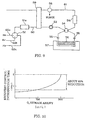
- the O 2 storage ability of the light-off catalyst 11 is set to be equal to or less than about 150 cc/liter (when measured according to the oxygen pulse method), which is less than the O 2 storage ability (200 to 500 cc/liter when measured according to the oxygen pulse method) of generally used underfloor catalysts (for example, exhaust gas purifying means including the lean NOx catalyst 13 and the three way catalyst 14), for the reason as described below with reference to Fig. 10.
- Fig. 10 shows a result of an experiment on the introduction time of recovery control, namely, a period of time in which the recovery control is performed, when the O 2 storage ability of the light-off catalyst 11 measured by the oxygen pulse method is varied.
- the exhaust gas purifying apparatus used in this experiment is constructed such that the light-off catalyst 11 having a volume of about 0.7 liters is provided on the upstream side of the exhaust gas purifying means including the lean NOx catalyst 13 having a volume of about 1.3 liters and the three way catalyst 14 having a volume of about 1.0 liter.
- the engine was kept operating for about 60 seconds in the lean burn mode, with the air-fuel ratio (A/F ratio) being controlled to about 30, and the recovery control introduction time required for completely release NOx adsorbed on the lean NOx catalyst 13 was measured.
- the recovery control introduction time is relatively short when the O 2 storage ability of the light-off catalyst 11 measured by the oxygen pulse method is equal to or less than about 150 cc/liter. If the O 2 storage ability of the light-off catalyst 11 becomes greater than about 150 cc/liter, however, the recovery control introduction time is rapidly increased.
- the O 2 storage capability of the light-off catalyst 11 is controlled to be equal to or less than about 150 cc / liter, the recovery control introduction time is reduced, and therefore the O 2 storage capability of the light-off catalyst 11 is considered as being low enough to prevent HC or CO, for example, from being oxidized by the catalyst 11.
- the rate of fuel consumption of the engine is reduced by about 60% when using the exhaust gas purifying apparatus including the light-off catalyst 11 having about 150 cc/liter of O 2 storage ability measured according to the oxygen pulse method, as compared with the case where the light-off catalyst 11 has about 300 cc/liter of O 2 storage ability as measured by the oxygen pulse method.
- an amount of an additive, such as ceria (CeO 2 ), contained in the light-off catalyst 11 and having an O 2 storage function is controlled to be not greater than 25g per one-liter volume of the light-off catalyst 11 (25g/liter or less), or may be zero, so that the amount of oxygen that can be stored in the light-off catalyst becomes less than 150 cc per one-liter volume of the light-off catalyst 11 (namely, the oxygen amount is less than 150cc/liter).
- the O 2 storage ability of the light-off catalyst 11 measured by the above-described oxygen pulse method is decreased.
- the amount of ceria (CeO 2 ) added to the light-off catalyst 11 is reduced, or absolutely no ceria (CeO 2 ) is added to the light-off catalyst 11, as shown in Fig. 2(a).
- the light-off catalyst 11 has a multi-layer structure as shown in Fig. 2(b) in which a two-layer structure consisting of A layer and B layer is illustrated by way of example, a part of the layers (for example, only A layer or B layer) may contain no ceria (CeO 2 ) at all.
- the light-off catalyst 11 By reducing the content of ceria (CeO 2 ) in the light-off catalyst 11 in the above manner, the light-off catalyst 11 is prevented from oxidizing HC or CO that is supplied to the lean NOx catalyst 13 during the recovery control or regeneration control, and therefore, NOx or SOx that has been adsorbed on the lean NOx catalyst 13 can be surely released from the catalyst 13 without incurring reduction in the fuel economy, thus assuring improved durability of the lean NOx catalyst 13.
- the air-fuel ratio needs to be more accurately controlled so that HC or CO will not be emitted during a rich burn operation of the engine when it starts operating in a cold state.
- the three way catalyst 14 is located on the downstream side (underfloor side) of the exhaust passage 3, and serves to reduce CO, HC, and NOx contained in the exhaust gas particularly after the engine has warmed up.
- the three way catalyst 14 has a function of reducing CO, HC, and NOx in the exhaust gas while the engine is operating in the stoichiometric feedback operating mode, and also has a function of oxidizing CO and HC while the engine is operating in the lean burn mode.
- the light-off catalyst 11 contains no ceria (CeO 2 ) or a reduced amount of ceria (CeO 2 ), the O 2 storage ability of the catalyst 11 is decreased, and the efficiency of reducing HC in the exhaust gas may deteriorate.
- ceria (CeO 2 ) having the O 2 storage function is added to the three way catalyst 14, to improve the efficiency of reducing HC in the exhaust gas.
- the lean NOx catalyst 6A is located upstream of the three way catalyst 14 in the exhaust passage 3 (underfloor-side exhaust passage 3), and is capable of sufficiently reducing or converting NOx in the exhaust gas even while the engine is operating in a lean burn mode with a large air-fuel ratio for the sake of improved fuel economy.
- the lean NOx catalyst 6A may be an adsorption-type or trapping type lean NOx catalyst, which purries the exhaust gas by adsorbing NOx on the catalyst and thus reducing NOx.
- the lean NOx catalyst 6A includes an alumina (Al 2 O 3 ) substrate or support, and a metal component M, such as barium (Ba), as an adsorbent, and platinum (Pt) as an active metal, which are both carried on or supported by the substrate.
- the metal component M supported by the lean NOx catalyst 13 functions to adsorb NOx contained in the exhaust gas under an oxygen excessive atmosphere, and release the adsorbed NOx when the oxygen concentration is reduced.
- the metal component M may include at least one of barium (Ba), sodium (Na), and potassium (K), for example.
- the lean NOx catalyst 13 uses alumina Al 2 O 3 for forming the substrate, zirconium oxide or zirconia (ZrO 2 ), or the like, may also be used.
- the lean NOx catalyst 13 may be constructed to provide a three-way catalytic function.
- barium (Ba) as an adsorbent supported by the lean NOx catalyst 13, reacts with O 2 , to provide barium oxide BaO on the surface of the catalyst 13, and the barium oxide BaO further reacts with CO, or the like, in the exhaust gas, to thus produce barium carbonate BaCO 3 .
- the barium nitrate Ba(NO 3 ) 2 adsorbed on the lean NOx catalyst 13 reacts with CO in the exhaust gas on the surface of platinum Pt, to produce NO 2 and barium carbonate BaCO 3 , and NO 2 thus produced is released from the lean NOx catalyst 13.
- This reaction is represented by the following formula (2): Ba(NO 3 ) 2 + CO ⁇ BaCO 3 + 2NO + O 2 where 2NO + O 2 ⁇ 2NO 2 (through part of NO is released as it is.)
- the released NO 2 is reduced by unburned HC, H 2 , and CO contained in the exhaust gas, and discharged as N 2 , as expressed by (NO + CO ⁇ 1/2 N 2 + CO 2 ), (NO + H 2 ⁇ 1/2 N 2 + H 2 O).
- barium nitrate Ba(NO 3 ) 2 and barium carbonate BaCO 3 are present in chemical equilibrium on the lean NOx catalyst 13, and the reaction in each direction occurs depending upon the atmosphere surrounding the lean NOx catalyst 13.
- the lean NOx catalyst 6A also functions to adsorb SOx in the exhaust gas in the presence of an oxygen excessive atmosphere, and release part of the adsorbed SOx in a certain high-temperature atmosphere when the oxygen concentration is reduced.
- O 2 is adsorbed on the surface of platinum (Pt) in an oxygen excessive atmosphere (lean atmosphere), and SO 2 in the exhaust gas reacts with O 2 on the surface of the platinum Pt, to produce SO 3 (2SO 2 + O 2 ⁇ 2SO 3 ), as shown in Fig. 4(a).
- the SO 2 is discharged as a result of combustion of sulfur components contained in the fuel or lubricating oil.
- the lean NOx catalyst 13 In order to reduce NOx by using the NOx adsorbing and releasing function, the lean NOx catalyst 13 needs to release NOx once a certain amount of NOx is adsorbed thereon.
- barium carbonate BaCO 3 and barium sulfate BaSO 4 are present in chemical equilibrium, and the reaction in each direction between BaCO 3 and BaSO 4 is likely to occur depending upon the atmosphere surrounding the lean NOx catalyst 13. More specifically, as the air-fuel ratio of the exhaust gas is reduced (namely, as the air-fuel ratio becomes richer), barium sulfate BaSO 4 is more likely to be dissolved, and barium carbonate BaCO 3 is more likely to be produced. To the contrary, as the air-fuel ratio of the exhaust gas is increased (namely, as the air-fuel ratio becomes lean), barium carbonate BaCO 4 is more likely to be dissolved, and barium sulfate BaSO 4 is more likely to be produced.
- barium sulfate BaSO 4 is generally unlikely to be dissolved, and therefore a significant amount of barium sulfate remains undissolved even if the oxygen concentration is reduced (namely, the air-fuel ratio becomes richer).
- barium nitrate Ba(NO 3 ) 2 corresponding to the amount of barium used is not produced, and the NOx converting capability of the lean NOx catalyst 13 is decreased or deteriorated, which is called "S poisoning".
- the lean NOx catalyst 13 is required to release SOx that has been adsorbed thereon.
- the lean NOx catalyst 13 may deteriorate and its NOx conversion efficiency may be significantly decreased before it reaches the target lifetime (for example, about 100,000 km of vehicle running distance). Even in this case, the concentration of NOx released into the atmosphere needs to be controlled so as not to exceed an allowable value regulated by the law.
- the lean burn internal combustion engine is adapted to perform recovery control for releasing adsorbed NOx and thus recovering or resuming the NOx conversion efficiency of the lean NOx catalyst 13 to a desired level when the efficiency is decreased due to adsorption of NOx, and also perform regeneration control for releasing adsorbed SOx and regenerating the lean NOx catalyst 13 when the NOx conversion efficiency is decreased due to adsorption of SOx on the catalyst 13.
- the ECU 20 of the lean burn internal combustion engine of the present embodiment is provided with NOx conversion efficiency calculating means 21, NOx conversion efficiency determining means 22, operation mode setting means 23, operation mode selecting means 24, and fuel injection control means 25, as shown in the functional block diagram of Fig. 5.
- the calculation of the NOx conversion efficiency by the NOx conversion efficiency calculating means 21 is performed a certain period of time after the engine operating mode is changed to a lean burn mode, such as an intake lean burn mode or a compression lean burn mode.
- the NOx conversion efficiency calculating means 21 is adapted to read a count value of a timer 29, and start calculating when the count value reaches a preset value.
- the NOx conversion efficiency determining means 22 determines if there is a need to perform any one of the recovery control for resuming the NOx conversion efficiency of the lean NOx catalyst 13 to the original level when the NOx conversion efficiency is decreased due to adsorption of NOx, and the regeneration control for regenerating the lean NOx catalyst 13 when the NOx conversion efficiency is decreased due to adsorption of SOx on the lean NOx catalyst 13.
- the NOx conversion efficiency determining means 22 includes recovery control determining means 22A, and regeneration control determining means 22B.
- the recovery control determining means 22A serves to check if a certain period of time (for example, about 60 seconds) has elapsed since the engine starts operating in a lean operation mode, such as an intake lean operation mode or a compression lean operation mode, to determine whether the recovery control needs to be performed or not. To this end, count values of the timer 29 are fed to the recovery control determining means 22A.
- the recovery control determining means 22A determines that the certain period of time (for example, about 60 seconds) has elapsed since the engine starts operating in the lean operation mode, it determines the necessity of the recovery control, and generates an appropriate signal to additional fuel injection control means 27 provided in fuel injection control means 25 as described later.
- the certain period of time for example, about 60 seconds
- the regeneration control determining means 22B checks if the NOx conversion efficiency calculated by the NOx conversion efficiency calculating means 21 after the recovery control is smaller than a threshold value "a" for the regeneration control, to determine whether the regeneration control needs to be performed or not.
- the regeneration control determining means 22B determines that the NOx conversion efficiency after the recovery control is less than the threshold value "a", it determines that the regeneration control needs to be performed, and sends an appropriate signal to the additional fuel injection control means 27 provided in the fuel injection control means 25 as described later.
- the threshold value "a" for the regeneration control is set to a value of NOx conversion efficiency of the lean NOx catalyst 13 obtained when the concentration of the sulfur component contained in the fuel is 100 ppm, and the running distance has reached about 10,000 km, as shown in Fig. 7.
- the fuel injection control means 25 includes normal fuel injection control means 26 and additional fuel injection control means 27.
- the additional fuel injection control means 27 controls the operation of the fuel injection valve 8, to perform the recovery control by injecting an additional fuel when the recovery control determining means 22A determines the necessity of the recovery control, and performs the regeneration control by injection an addition fuel when the regeneration control determining means 22B determines the necessity of the regeneration control.
- the addition fuel injection control means 27 sets an injection starting time T INJ at which the additional fuel injection is started, based on detected information (for example, engine speed and engine load) received from various sensors 28, and sets a period of time (injection time) during which the additional fuel is injected in each cycle.
- the injection starting time T ING and injection time of the additional fuel injection performed, as the recovery control, are set as shown in Fig. 6(a), so that a fuel-rich atmosphere having a reduced oxygen concentration is produced around the lean NOx catalyst 13.
- the air-fuel ratio is set to about 13, and the additional fuel is injected for about 2 seconds.
- the timer 29 starts counting once the additional fuel injection as the recovery control is started, and the count value of the time 29 is fed or sent to the additional fuel injection control means 27.
- the additional fuel injection may also be called “rich spike” or “rich pulse” since the control intends to temporarily produce a rich atmosphere around the lean NOx catalyst 13.
- the recovery control is performed for the following reason.
- an oxygen excessive atmosphere (lean atmosphere) is produced around the lean NOx catalyst 13, and the reaction as indicated by the formula (1) takes place.
- the engine continues to operate in the lean operation mode for a certain period of time (for example, about 60 seconds) or longer, a large quantity of NOx is adsorbed on the lean NOx catalyst 13, and the NOx conversion efficiency of the lean NOx catalyst 13 is gradually decreased.
- the additional fuel injection control means 27 performs recovery control by injecting an additional fuel into the combustion chamber, to encourage the reaction as indicated in the above-indicated formula (2), thereby to release NOx from the lean NOx catalyst 13.
- the NOx conversion efficiency of the lean NOx catalyst 13 can be improved, as shown in Fig. 6(b). It is to be noted that Fig. 6(b) is an enlarged view of a portion denoted by X in Fig. 7.
- the injection starting time T INJ and the injection time in the additional fuel injection performed as the regeneration control are respectively determined so that a rich atmosphere (for example, A/F is equal to about 12) having a reduced oxygen concentration and a certain temperature (for example, about 600°C or higher) is produced around the lean NOx catalyst 13.
- the additional fuel injection, as the recovery control, is conducted for a predetermined period of time (for example, about 3 minutes).
- the injection starting time T INJ is set so that the additional fuel injection control means 27 performs additional fuel injection as the regeneration control during a period between the middle period of the expansion stroke of each cylinder and the later period of the exhaust stroke, that is, in a heat remaining period in which the heat generated by main combustion due to normal fuel injection still remains in the combustion chamber.
- the injection starting time T INJ is set in the above manner, because the fuel that is additionally injected into the combustion chamber should be burned (or re-burned) without fail, so that a rich atmosphere having a reduced oxygen concentration and a high temperature (for example, about 600°C) is produced around the lean NOx catalyst 13, to release SOx adsorbed on the lean NOx catalyst 13.
- a rich atmosphere having a reduced oxygen concentration and a high temperature for example, about 600°C
- the additional fuel injection control means 27 sets the injection starting time T ING by correcting a basic fuel injection starting time Tb ING based on which the additional fuel is injected in the later period of the expansion stroke or later, depending upon the coolant temperature W, EGR amount, and the ignition timing T IG for main combustion.
- the additional fuel injection control means 27 also sets the injector driving time or period t PLUS , by correcting the basic driving time tB based on which the additional fuel is injected during or after the expansion stroke, depending upon the injection start time T ING , and catalyst temperature C.C.
- the regeneration control is performed for the following reason. Even if the rich pulse, or recovery control of the lean NOx catalyst 13 is performed at certain time intervals (for example, about 60 seconds), the reaction as indicated by the above-indicated formula (3) also occurs on the lean NOx catalyst 13 when it is surrounded by an oxygen excessive atmosphere (lean atmosphere), and therefore SOx is gradually adsorbed onto the lean NOx catalyst 13, with a result of adsorption of barium sulfate BaSO 4 on the lean NOx catalyst 13. Even when the oxygen concentration around the lean NOx catalyst 13 is reduced (the exhaust air-fuel ratio becomes richer), the barium sulfate BaSO 4 is not dissolved, but kept being adsorbed on the lean NOx catalyst 13. Consequently, barium nitrate Ba(NO 3 ) 2 corresponding to the amount of barium Ba used for adsorbing SOx is no longer produced, and the NOx conversion capability of the lean NOx catalyst is decreased.
- the timer 29 starts counting when the additional fuel injection control, as regeneration control, is started, and the count value of the timer 29 is continuously fed to the additional fuel injection control means 25.
- the solid line A indicates the NOx conversion efficiency after the recovery control
- the solid line B indicates the NOx conversion efficiency after the regeneration control.
- the recovery control and regeneration control are performed by executing a control routine as shown in the flowchart of Fig. 8.
- step S10 is executed to operate the engine in the recovery control mode.
- the following processing is performed, though details of the control are not shown in Fig. 8.
- the amount of NOx adsorbed on the lean NOx catalyst 13 gradually increases as the engine operates in the compression lean operation mode or intake lean operation mode. In order to recover or resume the NOx conversion efficiency of the lean NOx catalyst 13 to a desired level, therefore, it is determined whether the recovery control needs to be performed to release the adsorbed NOx from the lean NOx catalyst 13.
- the recovery control determining means 22A judges the necessity of the recovery control, by determining whether the operation of the engine in the intake lean operation mode or compression lean operation mode has lasted for a certain period of time (for example, about 60 seconds) or not. If it is determined from the result of the above judgement that the recovery control needs to be performed, the additional fuel injection control means 27 controls the fuel injector 8 to inject an additional fuel (or generate a rich pulse), to thus perform the recovery control.
- the light-off catalyst 11 contains a small or zero amount of ceria (CeO 2 ) in the present embodiment, CO supplied under the recovery control is prevented from being oxidized and consumed by O 2 stored in the ceria (CeO 2 ) of the light-off catalyst 11, and can be used for releasing the adsorbed NOx from the lean NOx catalyst 13.
- the recovery control as described above is performed at given time intervals (for example, about 60 seconds), to release the adsorbed NOx from the catalyst, the amount of SOx that is also adsorbed on the lean NOx catalyst 13 gradually increases since the adsorbed SOx cannot be released by the above-described recovery control. Consequently, the NOx conversion efficiency of the lean NOx catalyst 13 is deteriorated by the time when the vehicle running distance reaches, for example, about 10,000 km.
- step S20 the NOx conversion efficiency calculating means 21 calculates the NOx conversion efficiency ⁇ of the lean NOx catalyst 13 after the recovery control is performed.
- step S30 the regeneration control determining means 22B determines whether or not the NOx conversion efficiency ⁇ , after the recovery control, is less than the threshold value "a" for judging the necessity of the regeneration control.
- step S10 If it is determined that the NOx conversion efficiency ⁇ , after the recovery control, is equal to or greater than the threshold value "a", the control flow returns to S10 since the regeneration control has not been required to be performed. Thus, the processing of step S10 to step S30 is repeated until the NOx conversion efficiency ⁇ , calculated after the recovery control, becomes less than the threshold value "a" for the regeneration control.
- the control flow goes to step S40, and the engine is operated in the regeneration control mode.
- the additional fuel injection control means 27 controls the injector 8 to inject an additional fuel to regenerate the lean NOx catalyst 13.
- CO supplied by the regeneration control is prevented from being oxidized and consumed by O 2 stored in ceria (CeO 2 ) of the light-off catalyst 11, and therefore the adsorbed SOx can be surely released from the lean NOx catalyst 13.
- step S10 The above-described control routine including step S10 through step S40 is repeated.
- the exhaust gas purifying apparatus of the internal combustion engine according to one embodiment of the invention is constructed as described above, and thus provides the functions and effects as described below.
- the light-off catalyst 11 provided immediately downstream of the engine serves to reduce HC in the exhaust gas while the engine is operating in the cold state.
- the light-off catalyst 11 and the three way catalyst 14 serve to reduce HC, CO, and NOx in the exhaust gas.
- the light-off catalyst 11 and three way catalyst 14 cannot reduce NOx by utilizing their purifying characteristics, but the lean NOx catalyst 13 adsorbs NOx in the exhaust gas, and prevents the NOx from being discharged into the atmosphere.
- the recovery control is performed (a rich pulse is generated) when the NOx conversion efficiency is reduced.
- the recovery control an atmosphere having a reduced oxygen concentration is produced around the lean NOx catalyst 13, and NOx that has been adsorbed on the lean NOx catalyst 13 is released, to resume the NOx conversion efficiency to the desired level.
- the light-off catalyst 11 of the present embodiment contains only a small amount or none of ceria (CeO 2 ), CO that is supplied under the recovery control is prevented from being oxidized by O 2 stored in ceria (CeO 2 ) of the light-off catalyst 11. Accordingly, the NOx adsorbed on the lean NOx catalyst 13 can be surely released from the catalyst 13, and the NOx conversion efficiency is resumed to the desired level.
- the regeneration control is performed, in which an atmosphere having a reduced oxygen concentration is produced around the lean NOx catalyst 13, so that the adsorbed SOx is released from the lean NOx catalyst 13.
- the lean NOx catalyst 13 is regenerated, to thus provide an improved NOx conversion efficiency.
- the light-off catalyst 11 of the present embodiment contains a small amount or none of ceria (CeO 2 ), CO that is supplied under the regeneration control is prevented from being oxidized by O 2 stored in ceria (CeO 2 ) of the light-off catalyst 11. Accordingly, the SOx adsorbed on the lean NOx catalyst 13 can be surely released from the catalyst 13, and the lean NOx catalyst 13 can be thus regenerated.
- the light-off catalyst 11 provided in the exhaust passage on the upstream side of the NOx catalyst is able to reduce a sufficient amount of HC in the exhaust gas while the engine starts operating in the cold state. Also, when the NOx purifying efficiency is decreased due to adsorption of NOx or SOx on the lean NOx catalyst 13, the adsorbed NOx or SOx can be surely released from the lean NOx catalyst 13, to ensure improved durability of the catalyst 13, since the light-off catalyst 11 contains only a small amount or none of ceria (CeO 2 ), and has a low O 2 storage capability.
- the exhaust gas purifying means is constructed such that the three way catalyst 14 is provided as a separate component located downstream of the lean NOx catalyst 13. It is, however, possible to provide a single catalyst that has both the function of the lean NOx catalyst and the function of the three way catalyst. In this case, the O 2 storage ability of the light-off catalyst 11 may be set to be lower than that of the single catalyst.
- the engine operation when the lean NOx catalyst 13 suffers from S poisoning, the engine operation may be controlled using a narrowed or reduced lean burn operation region, and the function of the three way catalyst 14, as well as that of the lean NOx catalyst 13, may be effectively utilized to avoid an increase in the NOx component in the exhaust gas.
- the lifetime of the lean NOx catalyst 13 can be extended or prolonged, and the increase of the NOx component in the exhaust gas can be avoided, only by narrowing the lean burn operation region in the control of the engine operation.
- the recovery control is performed by injecting an additional fuel under control of the additional fuel injection control means 27 to produce a rich atmosphere around the lean NOx catalyst 13.
- the method of producing the rich atmosphere around the lean NOx catalyst 13 as the recovery control is not limited to this, but any other method may be employed.
- the operating mode of the engine may be changed to the rich burn mode.
- the regeneration control is performed by injecting an additional fuel is injected under control of the additional fuel injection control means 27, to produce a rich atmosphere around the lean NOx catalyst 13, and increase the exhaust gas temperature.
- the method of producing the rich atmosphere and increasing the exhaust gas temperature is not limited to this, but any other method may be employed.
- the engine may operate with a fuel-rich mixture, or the ignition timing may be retarded or delayed, or other device (such as electric heating catalyst) may be used.
- the NOx sensors are provided on the upstream and downstream sides of the lean NOx catalyst 13, for the purpose of calculating the NOx conversion efficiency of the lean NOx catalyst 13.
- the present invention is not limited to this arrangement, but only one NOx sensor may be provided downstream of the lean NOx catalyst 13, for detecting the amount of the NOx in the exhaust gas emitted from the exhaust gas purifying device 6.
- the amount of NOx in the exhaust gas that is supplied to the exhaust gas purifying device 6 may be obtained from a preset NOx amount stored in the ECU according to the engine operating conditions, and deterioration of the lean NOx catalyst 13 may be estimated by comparing the detected value of the NOx sensor and the value stored in the ECU.
- exhaust gas purifying apparatus of the illustrated embodiment is used with the in-cylinder injection type internal combustion engine
- present invention may also be applied to other type of engine, provided that the engine is capable of operating in a lean burn mode.
- the regeneration control is performed for releasing SOx adsorbed on the lean NOx catalyst 13, thereby to prevent the lean NOx catalyst 13 from being poisoned by the sulfur component in the exhaust gas (S poisoning).
- S poisoning the sulfur component in the exhaust gas
- the method of preventing the S poisoning of the lean NOx catalyst 13 is not limited to this, but the following method may be employed.
- An SOx catalyst (S-Trap) 12 that adsorbs the sulfur component (SOx) in the exhaust gas may be disposed upstream of the lean NOx catalyst 13 in the exhaust passage 3, as indicated by two-dot chain line in Fig. 1, in order to prevent S poisoning of the lean NOx catalyst 13.
- the SOx catalyst 12 which serves to reduce SOx in the exhaust gas by adsorbing SOx thereon, includes a substrate or support made of alumina Al 2 O 3 , and a metal component M', such as strontium (Sr), as an adsorbent, and platinum (Pt) as an active metal, which are supported by the alumina substrate. While alumina (Al 2 O 3 ) is used for forming the substrate or support in the SOx catalyst 6B of this example, a substrate made of other material, such as zirconia (ZrO 2 ), may also be used.
- the metal component M' supported by the SOx catalyst 6B functions to adsorb SOx in the exhaust gas under an oxygen excessive atmosphere, and release the component M' hardly adsorbs NOx when the air-fuel ratio of the exhaust gas is lean, namely, when the oxygen concentration is increased.
- the metal component M' is selected from strontium (Sr), potassium (Ca), zinc (Zn), and manganese (Mn).
- an additional fuel may be injected into the combustion chamber to produce a rich atmosphere having a reduced oxygen concentration, around the SOx catalyst 6B, so that the adsorbed SOx is released from the SOx catalyst 6B, thus preventing a reduction in the SOx conversion ability of the SOx catalyst 6B.
- the light-off catalyst since the light-off catalyst has a low O 2 storage ability, CO contained in the exhaust gas is not oxidized by the light-off catalyst, and is thus able to release SOx from the catalyst, without affecting the fuel economy.
- While the SOx catalyst 12 is provided downstream of the light-off catalyst 11 in the exhaust passage 3, as a separate member from the light-off catalyst 11, a single catalyst may be provided which has both the three-way function of the light-off catalyst and the function of the SOx catalyst. In this case, since the light-off catalyst 11 contains only a small amount of ceria (CeO 2 ), SO 2 trapped by this catalyst is prevented from reacting with O 2 stored in the ceria (CeO 2 ) to provide SO 3 , which would be in turn adsorbed by the lean NOx catalyst 13.
- CeO 2 ceria
- the regeneration control may also be performed to release SOx adsorbed on the lean NOx catalyst 13.
- the light-off catalyst located upstream of the exhaust gas purifying means in the exhaust passage is able to certainly reduce HC in the exhaust gas when the engine starts operation in a cold state, for example.
- the light-off catalyst has a low O 2 storage ability, and is therefore able to allow CO to pass therethrough without oxidizing it, thereby to ensure a sufficient amount of CO for releasing NOx or SOx from the exhaust gas purifying means, without decreasing the fuel efficiency.
Abstract
Description
- The present invention relates to an exhaust gas purifying apparatus of an internal combustion engine, and in particular to such an exhaust gas purifying apparatus that is able to highly efficiently reduce harmful components, particularly NOx (nitrogen oxides), contained in exhaust gases, for the internal combustion engine capable of operating with a fuel-lean air/fuel mixture.
- In recent years, internal combustion engines, capable of operating in a lean burn mode with a fuel-lean mixture, have been developed to achieve further improved fuel economy. In this type of internal combustion engine, it is difficult to reduce NOx in exhaust gases during the lean burn operation, by using a conventional three way catalyst having a function of reducing CO, HC and NOx in exhaust gases when the engine is operating at around the stoichiometric air/fuel ratio.
- In view of the above problem, a new type of catalyst (called adsorption type lean NOx catalyst or trap-type lean NOx catalyst) has been developed which has a function of adsorbing NOx in exhaust gas under an oxygen excessive atmosphere (or oxidizing atmosphere), and releasing the adsorbed NOx when the oxygen concentration of the exhaust gas is reduced.
- More specifically, the lean NOx serves to oxidize NOx in the exhaust gas to produce nitrates when it is surrounded by an atmosphere having a high oxygen concentration, thereby to adsorb NOx, and also serves to produce carbonates by causing reaction between the nitrates, adsorbed on the lean NOx catalyst, and CO in the exhaust gas when it is surrounded by a reducing atmosphere having a reduced oxygen concentration, thereby to release NOx. The NOx thus released from the lean NOx catalyst, is then converted into a harmless substance due to the three-way function of the lean NOx catalyst, or by means of a three way catalyst located downstream of the lean NOx catalyst.
- While NOx in the exhaust gas can be surely reduced by the lean NOx catalyst during the lean burn operation, it is still difficult to sufficiently reduce HC in the exhaust gas when the engine starts operating in a cold state, for example, only by using the lean NOx catalyst as described above.
- In order to reduce HC in the exhaust gas to a sufficiently low level upon start of the engine in a cold state, it has been proposed to provide a light-off catalyst (L/O catalyst, FCC: Front Catalytic Converter) immediately downstream of the engine and upstream of the conventional catalyst.
- Example of the light-off catalyst are disclosed in, for example, JP-A-8-294618, and JP-A-5-187230.
- As disclosed in the above-identified prior art documents, the light-off catalyst consists of a three way catalyst (TWC), and the three way catalyst or oxidizing catalyst used as the light-off catalyst contains, for example, ceria (CeO2) as an additive having a function of storing O2.
- While the engine operates in a stoichiometric feedback mode or a lean burn mode during normal running of the vehicle, it sometimes operates in a rich burn mode with a fuel-rich mixture when the vehicle is in a transient state, for example, when the vehicle is accelerating. In this case, since the amount of O2 contained in the exhaust gas is not sufficient to oxidize HC and CO, O2 stored in ceria (CeO2) of the light-off catalyst is utilized for oxidizing HC and CO, thereby to reduce HC to a sufficiently low level even during the transient rich burn operation of the engine.
- The use of both the lean NOx catalyst and the light-off catalyst as disclosed in the above prior art documents, however, suffers from a problem as follows: since the light-off catalyst has an O2 storage function, CO that is needed for releasing adsorbed NOx from the lean NOx catalyst in a reducing atmosphere is undesirably oxidized by the light-off catalyst, and a sufficient amount of CO cannot be supplied to the lean NOx catalyst. Thus, the NOx adsorbed on the lean NOx catalyst may not be sufficiently released from the catalyst because of the oxidation of CO by the light-off catalyst.
- In order to recover or resume the NOx conversion efficiency of the lean NOx catalyst to a nominal level, recovery control is performed to produce a rich atmosphere (of a small air-fuel ratio) having a reduced oxygen concentration around the lean NOx catalyst, thereby to release the adsorbed NOx from the lean NOx catalyst. As an example of the recovery control, an additional fuel is injected to the combustion chamber of the engine. Since CO supplied by the recovery control is oxidized and consumed by O2 stored in the additive (for example, ceria CeO2) of the light-off catalyst, NOx adsorbed on the lean NOx catalyst cannot be surely released from the catalyst, and the NOx conversion efficiency of the lean NOx catalyst cannot be resumed to the nominal level.
- It may be considered to control the air-fuel ratio to be even richer in order to resume the NOx conversion efficiency of the lean NOx catalyst to the desired level, but this method results in deterioration of the fuel efficiency or fuel economy, and is therefore undesirable.
- In the meantime, a sulfur component (S component) is contained in the fuel and lubricating oil, and such a sulfur component is also contained in exhaust gas. The lean NOx catalyst, therefore, serves to adsorb the sulfur component as well as NOx in a high oxygen concentration atmosphere. Namely, the sulfur component contained in the fuel or lubricating oil is burned in the combustion chamber, and then oxidized on the surface of the lean NOx catalyst, to provide SO3. A part of the SO3 then reacts with an adsorbent for adsorbing NOx on the lean NOx catalyst, to produce sulfates that are adsorbed on the lean NOx catalyst.
- While the nitrates and sulfates as described above are adsorbed on the lean NOx catalyst, the amount of sulfates remaining on the lean NOx catalyst increases with time, since the sulfates have higher stability in the form of salts than nitrates, and only a part of the sulfates dissolves in an atmosphere having a reduced oxygen concentration. With an increase in the remaining amount of sulfates, the ability of the lean NOx catalyst to adsorb NOx deteriorates with time, and the purifying efficiency (NOx conversion efficiency) of the lean NOx catalyst is decreased. This is called S poisoning.
- When the lean NOx catalyst suffers from the S poisoning as described above, it becomes necessary to release the sulfur component (SOx) from the lean NOx catalyst. Where both of the lean NOx catalyst and the light-off catalyst, as disclosed in the above prior art documents, are used, however, SOx adsorbed on the lean NOx catalyst cannot be sufficiently released since the light-off catalyst has a high O2 storage ability.
- To regenerate the lean NOx catalyst by producing an atmosphere having a reduced oxygen concentration around the lean NOx catalyst, and releasing SOx adsorbed on the lean NOx catalyst in the reducing atmosphere, regeneration control is performed by, for example, controlling the air-fuel ratio to be richer, to reduce the oxygen concentration of the exhaust gas. Since CO supplied under the regeneration control for releasing SOx reacts with O2 stored in an additive (for example, ceria CeO2) of the light-off catalyst, to be oxidized and consumed by the O2, the SOx adsorbed on the lean NOx catalyst cannot be released from the catalyst, and the lean NOx catalyst cannot be regenerated as desired.
- Also, SO2 emitted from the engine reacts with O2 stored in the additive of the light-off catalyst, to produce
- It is therefore an object of the present invention to provide an exhaust gas purifying apparatus of an internal combustion engine that is able to surely reduce HC in exhaust gas upon start of the engine in a cold state, and is also able to surely release NOx and SOx from a NOx catalyst when the NOx conversion efficiency is decreased due to adsorption of the NOx or SOx on the NOx catalyst, without decreasing the fuel efficiency, thus assuring improved durability of the NOx catalyst.
- To accomplish the above object, the present invention provides an exhaust gas purifying apparatus of an internal combustion engine wherein exhaust gas purifying means is provided in an exhaust passage of the engine, for adsorbing NOx in exhaust gas when the air-fuel ratio of the exhaust gas is lean, and releasing or reducing the adsorbed NOx when the oxygen concentration of the exhaust gas is reduced. Also, a light-off catalyst having a lower O2 storage ability than the exhaust gas purifying means is provided upstream of the exhaust gas purifying means in the exhaust passage. Further, the air-fuel ratio of the exhaust gas is controlled so that an atmosphere having a reduced oxygen concentration is produced around the exhaust gas purifying means when a NOx conversion efficiency of the exhaust gas purifying means is decreased.
- In the exhaust gas purifying apparatus as described above, when the NOx conversion efficiency is decreased due to adsorption of NOx or SOx on the exhaust gas purifying means, an additional fuel is injected into the combustion chamber of the engine, for example, to supply CO to the exhaust gas purifying means and produce an atmosphere having a reduced oxygen concentration around the exhaust gas purifying means. In this case, the CO supplied in this manner is prevented from being oxidized by the light-off catalyst, thus avoiding a reduction in the amount of CO supplied to the exhaust gas purifying means. Thus, NOx and SOx can be surely released from the exhaust gas purifying means, without decreasing the fuel efficiency, and the durability of the exhaust gas purifying means can be enhanced.
- In a preferred form of the present invention, the exhaust gas purifying means includes an NOx catalyst that adsorbs NOx in the exhaust gas when the air-fuel ratio of the exhaust gas is lean, and releases or reduces the adsorbed NOx when the oxygen concentration of the exhaust gas is reduced. The exhaust gas purifying means further includes a three way catalyst provided downstream of the NOx catalyst in the exhaust passage, for reducing harmful components in the exhaust gas when the air-fuel ratio of the exhaust gas is in the neighborhood of the stoichiometric ratio.
- The exhaust gas purifying means may consist of a single catalyst having the function of the NOx catalyst and the function of the three way catalyst as described above.
- The light-off catalyst may consist of a single catalyst that functions as a three way catalyst, and also functions as a SOx catalyst that adsorbs SOx when the air-fuel ratio of the exhaust gas is lean, and releases the adsorbed SOx when the exhaust air/fuel ratio is rich.
- The light-off catalyst is preferably constructed such that the amount of oxygen adsorbed on the catalyst is not greater than about 150 cc per one-liter volume of the catalyst when measured according to an oxygen pulse method. Thus, the O2 storage ability of the light-off catalyst is decreased.
- Also, the light-off catalyst is preferably constructed so that an oxygen component stored in the catalyst is not greater than about 25g per one-liter volume of the catalyst. Thus, the O2 storage ability of the light-off catalyst is advantageously decreased.
- The present invention will become more fully understood from the detailed description given hereinbelow and the accompanying drawings which are given by way of illustration only, and thus are not limitative of the present invention, and wherein:
- Fig. 1 is a schematic view showing the whole construction of an exhaust gas purifying apparatus of an internal combustion engine according to one embodiment of the present invention;
- Fig. 2(a) is a schematic view showing a light-off catalyst of the exhaust gas purifying apparatus of the embodiment of Fig. 1, wherein the light-off catalyst has a single-layer structure;
- Fig. 2(b) is a schematic view showing a light-off catalyst of the exhaust gas purifying apparatus of the embodiment of Fig. 1, wherein the light-off catalyst has a multi-layer structure;
- Fig. 3(a) through Fig. 3(b) are schematic views useful in explaining the principle of NOx conversion of a lean NOx catalyst of the exhaust gas purifying apparatus of Fig. 1 in the lean burn internal combustion engine, wherein Fig. 3(a) shows the structure of the lean NOx catalyst, Fig. 3(b) shows the NOx adsorbing function of the lean NOx catalyst, and Fig. 3(c) shows the NOx releasing function of the lean NOx catalyst;
- Fig. 4(a) and Fig. 4(b) are schematic views useful in explaining the functions of the lean NOx catalyst for adsorbing and releasing a sulfur component in the lean burn internal combustion engine, wherein Fig. 4(a) shows the function of adsorbing the sulfur component, and Fig. 4(b) shows the function of releasing the sulfur component;
- Fig. 5 is a functional block diagram schematically showing principal parts of a control system of the exhaust gas purifying apparatus of the internal combustion engine according to the embodiment of Fig. 1;
- Fig. 6(a) and Fig. 6(b) are graphs useful in explaining recovery control (rich pulse) performed in the exhaust gas purifying apparatus of the embodiment of Fig. 1, wherein Fig. 6(a) shows the air-fuel ratio of exhaust gas, and Fig. 6(b) shows the NOx conversion efficiency of the lean NOx catalyst;
- Fig. 7 is a graph useful in explaining regeneration control performed in the exhaust gas purifying apparatus of the internal combustion engine according to the embodiment of Fig. 1;
- Fig. 8 is a flowchart showing the recovery control, regeneration control, and control for narrowing a lean burn operation region, in the exhaust gas purifying apparatus of the internal combustion engine according to the embodiment of Fig. 1;
- Fig. 9 is a view showing the whole construction of a measurement device for measuring an O2 storage ability according to a conventional oxygen pulse method; and
- Fig. 10 is a graph showing an effect of the exhaust gas purifying apparatus of the internal combustion engine according to the embodiment of Fig. 1.
-
- Referring to Fig. 1 through Fig. 8, an exhaust gas purifying apparatus of an internal combustion engine according to one embodiment of the present invention will be described in detail.
- Initially, the internal combustion engine equipped with the exhaust gas purifying apparatus of the present embodiment will be described. The internal combustion engine, which is constructed as shown in Fig. 1, is a spark ignition type four-cycle engine that operates on the four-stroke cycle consisting of suction stroke, compression stroke, combustion/expansion stroke, and exhaust stroke. Also, the internal combustion engine of the present embodiment is constructed as an in-cylinder injection type engine in which the fuel is directly injected into a
combustion chamber 1. - An
intake passage 2 and anexhaust passage 3 are connected to thecombustion chamber 1 so that thesepassages chamber 1. Also, anintake valve 4 is provided for controlling fluid communication between theintake passage 2 and thecombustion chamber 1, and anexhaust valve 5 is provided for controlling fluid communication between theexhaust passage 3 and thecombustion chamber 1. - An air cleaner and a throttle valve (not shown) are provided in the
intake passage 2, and an exhaust gas purifyingapparatus 6 and a muffler (not shown) are provided in theexhaust passage 3. The exhaustgas purifying apparatus 6 will be described later in detail. - An injector (fuel injection valve) 8 is located in the engine with its opening being exposed to the
combustion chamber 1 in a cylinder of the engine, and serves to directly inject a fuel into thecombustion chamber 1. Naturally, theinjector 8 is installed in each cylinder of the engine. In the present embodiment, in which the engine is in the form of an in-line four-cylinder engine, for example, fourinjectors 8 are installed in the respective cylinders. - In the engine constructed as described above, an intake air that has passed through the air cleaner enters the
combustion chamber 1 through theintake valve 4 placed in the open position, such that the amount of the intake sir is controlled by the opening of the throttle valve (not shown). The intake air thus sucked into thecombustion chamber 1 is then mixed with a fuel that is directly injected by theinjector 8 based on a signal from an electronic control unit (ECU) 20 as control means. The mixture of the intake air and the fuel is burned in thecombustion chamber 1 upon ignition of anignition plug 7 at an appropriate timing, to generate engine torque, and exhaust gases are emitted from thecombustion chamber 1 into theexhaust passage 3. The exhaust gases are then passed through the exhaustgas purifying apparatus 6 for reducing three harmful components, CO, HC, NOx, contained in the gases, and then passed through the muffler for reducing noise, to be released into the atmosphere. - The engine is provided with various sensors, and detection signals from the sensors are transmitted to the
ECU 20. For example, an NOx sensor 9 (that will be called "upstream NOx sensor") is located upstream of the exhaustgas purifying apparatus 6 in theexhaust passage 3, and another NOx sensor 10 (that will be called "downstream NOx sensor") is located downstream of a lean NOx catalyst 13 (that will be described later) in theexhaust passage 3. The NOx conversion efficiency of the exhaustgas purifying apparatus 6 can be computed based on detected information from theupstream NOx sensor 9 anddownstream NOx sensor 10. The calculation of the NOx conversion efficiency will be described later. - More specifically, the engine is constructed so that the intake air flowing from the
intake passage 2 into thecombustion chamber 1 forms a vertical swirl (reverse tumble flow), and the vertical swirl thus formed in thecombustion chamber 1 is utilized to concentrate a small amount of the fuel in the vicinity of theignition plug 7 located at the top, central part of thecombustion chamber 1. As a result, an extremely lean air-fuel ratio is established in a chamber portion remote from theignition plug 7, while the stoichiometric air-fuel ratio or rich air-fuel ratio is established only in the vicinity of theignition plug 7. In this manner, stable stratified charge combustion (stratified, extreme-lean burn) can be realized in thecombustion chamber 1, assuring significantly reduced fuel consumption. In this case, the optimum fuel injection timing is in the later period of the compression stroke in which weak air flow prevents the fuel from dissipating too far by the time of ignition. - When the engine is desired to produce large output, the fuel from the
injector 8 is introduced uniformly into the entire volume of thecombustion chamber 1, and mixed in advance with the air to provide an air/fuel mixture having the stoichiometric air-fuel ratio or lean air/fuel ratio in theentire combustion chamber 1. While the larger output can be achieved by using the stoichiometric air/fuel mixture, rather than the lean mixture, the engine is able to produce a large output with high efficiency in both cases, by injecting the fuel in such timing that ensures sufficient atomization and vaporization of the fuel. In this case, the optimum fuel injection timing is determined to complete the fuel injection during the intake stroke, so that the intake air can be utilized for encouraging atomization and vaporization of the fuel. - The engine of the present embodiment operates in a selected one of four fuel combustion modes, i.e., an extreme lean burn mode (compression lean burn mode), a lean burn mode (intake lean burn mode), a stoichiometric operation mode (stoichiometric feedback operation mode), and a rich burn mode (open loop mode). In the extreme lean burn mode, the engine operates with an extremely lean air/fuel mixture (whose air-fuel ratio is considerably greater than the stoichiometric ratio), utilizing stratified charge combustion resulting from fuel injection during the compression stroke. In the intake lean burn mode, the engine operates with a relatively lean air/fuel mixture whose air/fuel ratio is greater than the stoichiometric ratio, but not as much as that of the air/fuel mixture used in the extreme lean burn mode as described above. In the stoichiometric operation mode, feedback control is performed based on information from an O2 sensor and others, so that the air/fuel ratio of the mixture becomes approximately equal to the stoichiometric ratio. In the rich burn mode (open loop mode), the engine operates with a fuel-rich air/fuel mixture (whose air-fuel ratio is less than the stoichiometric ratio).
- The operation of the engine is controlled by selecting one mode from various operation modes as described above. The operation mode is selected based on the engine speed Ne and the effective pressure Pe that represents a load condition of the vehicle. Namely, the compression lean burn mode (compression-L) is selected when the engine speed Ne is low, and the load Pe is small. As the engine speed Ne and the load Pe increase, the intake lean burn mode (intake-L), stoichiometric feedback operation mode (S/F), and the open loop mode (O/L) are selected in this order. The selection and setting of the operation mode will be further described later.
- The exhaust
gas purifying apparatus 6 according to the present embodiment will be now explained. - The exhaust
gas purifying apparatus 6 includes a light-off catalyst (L/O catalyst, FCC) 11, a lean NOx catalyst (NOx catalyst, NOx-TRAP) 13, and a three way catalyst (TWC) 14, as shown in Fig. 1. Thelean NOx catalyst 13 and the threeway catalyst 14 constitute exhaust gas purifying means. - The light-
off catalyst 11 includes a three way catalyst having a function of reducing CO, HC and NOx contained in the exhaust gas. The light-off catalyst 11 is located in theexhaust passage 3 immediately downstream of thecombustion chamber 1 of the engine, so that thecatalyst 11 reaches its activation temperature due to exposure to high-temperature exhaust gas immediately after the engine starts operating in a cold state. In particular, the light-off catalyst 11 serves to reduce HC in the exhaust gas upon the start of the engine in the cold state. The light-off catalyst 11 is located upstream of thelean NOx catalyst 13 in theexhaust passage 3. - The O2 storage ability of the light-
off catalyst 11 is set to be lower than that of the threeway catalyst 14. More specifically, the O2 storage ability of the light-off catalyst 11 is determined so that the amount of adsorption of oxygen per liter of catalyst volume is not greater than about 150 cc (namely, the oxygen adsorption amount is 150 cc / liter), when measured according to an oxygen pulse method. - An apparatus and a method for measuring the O2 storage ability according to a conventional oxygen pulse method will be now described.
- As shown in Fig. 9, the apparatus for measuring the O2 storage ability by the oxygen pulse method includes a
test tube 56 containing a specimen (in this example, a light-off catalyst containing ceria CeO2), asupply passage 60 through which a gas (He, air, or H2) is supplied to the specimen in thetest tube 56, adischarge passage 61 through which the gas is discharged from thetest tube 56, and afurnace 57 that heats thetest tube 56 to a certain temperature. - The
supply passage 60 is connected at its upstream end to aHe conduit 60a, anair conduit 60b, and a H2 conduit 60c, via aswitch cock 52, and connected at its downstream end to thetest tube 56 via aconnector 55. By operating theswitch cock 52 to an appropriate position, a desired one of He, air, and H2 can be introduced into thesupply passage 60, to be supplied to the specimen in thetest tube 56. - In the
supply passage 60 between theswitch cock 52 and thetest tube 56, aflow meter 51a and anoxygen pulse injector 53 are provided in this order as viewed from the upstream side of thepassage 60. Theflow meter 51a serves to detect the flow rate of the gas flowing through thesupply passage 60. Theoxygen pulse injector 53 is adapted to introduce oxygen in pulse form into thesupply passage 60 for measurement of the O2 storage ability. - A flow path switch
cock 54 is provided for connecting thesupply passage 60 and thedischarge passage 61. The flow path switchcock 54 can be selectively placed in a first position, in which the gas flowing through thesupply passage 60 is supplied to the specimen in thetest tube 56 upon measurement of the O2 storage ability, and a second position, in which the gas in thesupply passage 60 flows into thedischarge passage 61 while bypassing thetest tube 56. - In the
discharge passage 61 on the downstream side of theflow switch cock 54, aflow meter 51b and apurge cock 58 are located in this order as viewed from the upstream side of thepassage 61. Theflow meter 51b serves to detect the flow rate of the gas flowing through thedischarge passage 61. Thepurge cock 58 serves to discharge or release unnecessary gas into the atmosphere during a preliminary process before the measurement of the O2 storage ability. In addition, athermal conductivity detector 59 is provided for detecting the thermal conductivity of the gas that has passed through thetest tube 56. - Next, the method of measuring the O2 storage ability by the oxygen pulse method, using the above measurement apparatus, will be described.
- Before the measurement of the O2 storage ability is initiated, a preliminary process is conducted to remove oxygen that has already been adsorbed on the specimen.
- In this preliminary process, the specimen is introduced into the
test tube 56, which is then connected, viaconnectors 55, to the main body (more specifically,supply passage 60 and discharge passage 61) of the measurement apparatus, and thefurnace 57 is set in position. Then, theswitch cock 52 is switched to a position for communicating thesupply passage 60 with the H2 conduit 60c, so that H2 is supplied to thetest tube 56 through thesupply passage 60, and the specimen is maintained in this state for 30 minutes while being kept at abut 450°C . - In this case, the flow rate of the gas introduced into the
test tube 56 is controlled to a certain value by means of theflow meter 51a. Also, thepurge cock 58 is placed in the open position, so that the gas flowing into thedischarge passage 61 is released into the atmosphere. - In the process as described above, oxygen that is adsorbed on the specimen is caused to react with H2, and released from the specimen, to establish a desired condition in which no oxygen is adsorbed on the specimen.
- Subsequently, the
switch cock 52 is operated to a position for communicating thesupply passage 60 with theHe conduit 60a, so that He is supplied to thetest tube 56 through thesupply passage 60, and the specimen is maintained in this state for 30 min., while being cooled down to room temperature. The thus supplied He is adapted to remove H2 that has been supplied in the above process for releasing oxygen from the specimen. - By conducting the preliminary process as described above, the O2 storage ability of the specimen can be measured with improved accuracy.
- After the preliminary process is completed, the O2 storage ability is actually measured in the following manner.
- To measure the O2 storage ability, oxygen pulses are introduced from the
oxygen pulse injector 53 into thesupply passage 60, so that oxygen is supplied to the specimen in thetest tube 56. - After the adsorption of oxygen onto the specimen reaches a steady state (in which the specimen is supposed to be saturated with oxygen), oxygen pulses are introduced from the
oxygen pulse injector 53 for a certain number of times (for example, twice), to be supplied to the specimen in thetest tube 56, and the supply of the oxygen is finished. - During the measurement of the O2 storage ability, the gas is inhibited from being introduced from the
switch cock 52, and thepurge cock 58 is held in the closed state. Each time an oxygen pulse is supplied from theoxygen pulse injector 53 into thesupply passage 60, the thermal conductivity is detected by thethermal conductivity detector 59. - Also, calibration of the oxygen amount is conducted by operating the flow path switch
cock 54 to the position for bypassing thetest tube 56. In the calibration of the oxygen amount, the relationship between the amount of oxygen supplied in pulse form from theoxygen pulse injector 53, and an area of a peak value detected by thethermal conductivity detector 59 with respect to this amount of oxygen is obtained. - Based on the relationship between the oxygen amount and the area of the peak value obtained through the calibration of the oxygen amount, an amount of oxygen adsorbed on the specimen is calculated from a difference between the average value of the areas of peak values detected by the
thermal conductivity detector 59 after the specimen reaches the steady state, and the area of the peak value detected by thethermal conductivity detector 59 each time the oxygen is supplied from theoxygen pulse injector 53 before the specimen reaches the steady state, and the oxygen adsorption amount (cc/liter) per liter of the specimen, namely, the O2 storage ability, can be calculated from the sum of the oxygen adsorption amounts. - The O2 storage ability of the light-
off catalyst 11 is set to be equal to or less than about 150 cc/liter (when measured according to the oxygen pulse method), which is less than the O2 storage ability (200 to 500 cc/liter when measured according to the oxygen pulse method) of generally used underfloor catalysts (for example, exhaust gas purifying means including thelean NOx catalyst 13 and the three way catalyst 14), for the reason as described below with reference to Fig. 10. - Fig. 10 shows a result of an experiment on the introduction time of recovery control, namely, a period of time in which the recovery control is performed, when the O2 storage ability of the light-
off catalyst 11 measured by the oxygen pulse method is varied. - The exhaust gas purifying apparatus used in this experiment is constructed such that the light-
off catalyst 11 having a volume of about 0.7 liters is provided on the upstream side of the exhaust gas purifying means including thelean NOx catalyst 13 having a volume of about 1.3 liters and the threeway catalyst 14 having a volume of about 1.0 liter. In the experiment, the engine was kept operating for about 60 seconds in the lean burn mode, with the air-fuel ratio (A/F ratio) being controlled to about 30, and the recovery control introduction time required for completely release NOx adsorbed on thelean NOx catalyst 13 was measured. - As is understood from the result of the experiment shown in Fig. 10, the recovery control introduction time is relatively short when the O2 storage ability of the light-
off catalyst 11 measured by the oxygen pulse method is equal to or less than about 150 cc/liter. If the O2 storage ability of the light-off catalyst 11 becomes greater than about 150 cc/liter, however, the recovery control introduction time is rapidly increased. - Thus, if the O2 storage capability of the light-
off catalyst 11 is controlled to be equal to or less than about 150 cc / liter, the recovery control introduction time is reduced, and therefore the O2 storage capability of the light-off catalyst 11 is considered as being low enough to prevent HC or CO, for example, from being oxidized by thecatalyst 11. - For example, the rate of fuel consumption of the engine is reduced by about 60% when using the exhaust gas purifying apparatus including the light-
off catalyst 11 having about 150 cc/liter of O2 storage ability measured according to the oxygen pulse method, as compared with the case where the light-off catalyst 11 has about 300 cc/liter of O2 storage ability as measured by the oxygen pulse method. In view of the reduction in the rate of the fuel consumption, therefore, it is desirable to control the O2 storage ability of the light-off catalyst 11 to be equal to or less than about 150 cc/liter. - In view of regeneration control for releasing a sulfur component from the
lean NOx catalyst 13, it is also desirable to control the O2 storage ability of the light-off catalyst 11 to be equal to or less than 150 cc/liter, as in the case of the recovery control for thelean NOx catalyst 13. - In the present embodiment, therefore, an amount of an additive, such as ceria (CeO2), contained in the light-
off catalyst 11 and having an O2 storage function is controlled to be not greater than 25g per one-liter volume of the light-off catalyst 11 (25g/liter or less), or may be zero, so that the amount of oxygen that can be stored in the light-off catalyst becomes less than 150 cc per one-liter volume of the light-off catalyst 11 (namely, the oxygen amount is less than 150cc/liter). Thus, the O2 storage ability of the light-off catalyst 11 measured by the above-described oxygen pulse method is decreased. - To decrease the O2 storage ability of the light-
off catalyst 11, the amount of ceria (CeO2) added to the light-off catalyst 11 is reduced, or absolutely no ceria (CeO2) is added to the light-off catalyst 11, as shown in Fig. 2(a). Where the light-off catalyst 11 has a multi-layer structure as shown in Fig. 2(b) in which a two-layer structure consisting of A layer and B layer is illustrated by way of example, a part of the layers (for example, only A layer or B layer) may contain no ceria (CeO2) at all. - By reducing the content of ceria (CeO2) in the light-
off catalyst 11 in the above manner, the light-off catalyst 11 is prevented from oxidizing HC or CO that is supplied to thelean NOx catalyst 13 during the recovery control or regeneration control, and therefore, NOx or SOx that has been adsorbed on thelean NOx catalyst 13 can be surely released from thecatalyst 13 without incurring reduction in the fuel economy, thus assuring improved durability of thelean NOx catalyst 13. - Where the content of ceria (CeO2) in the light-
off catalyst 11 is reduced as described above, the air-fuel ratio needs to be more accurately controlled so that HC or CO will not be emitted during a rich burn operation of the engine when it starts operating in a cold state. - With the content of ceria (CeO2) in the
light catalyst 11 reduced as described above, HC or CO to be supplied to the lean NOx catalyst under the recovery control or regeneration control as described later is prevented from being oxidized and consumed by O2 stored in the ceria (CeO2) of the light-off catalyst 11. - The three
way catalyst 14 is located on the downstream side (underfloor side) of theexhaust passage 3, and serves to reduce CO, HC, and NOx contained in the exhaust gas particularly after the engine has warmed up. - The three
way catalyst 14 has a function of reducing CO, HC, and NOx in the exhaust gas while the engine is operating in the stoichiometric feedback operating mode, and also has a function of oxidizing CO and HC while the engine is operating in the lean burn mode. - Since the light-
off catalyst 11 contains no ceria (CeO2) or a reduced amount of ceria (CeO2), the O2 storage ability of thecatalyst 11 is decreased, and the efficiency of reducing HC in the exhaust gas may deteriorate. In the present embodiment, therefore, ceria (CeO2) having the O2 storage function is added to the threeway catalyst 14, to improve the efficiency of reducing HC in the exhaust gas. - In the meantime, SOx released from the lean NOx catalyst under the regeneration control, as described later, reacts with HC existing around the catalyst, to be converted into a harmful substance, namely, H2S. Due to the improved O2 storage ability of the three
way catalyst 14 as described above, the H2S is oxidized by O2 stored in the threeway catalyst 14, and the amount of H2S released from thecatalyst 14 can be thus advantageously reduced. - The
lean NOx catalyst 6A is located upstream of the threeway catalyst 14 in the exhaust passage 3 (underfloor-side exhaust passage 3), and is capable of sufficiently reducing or converting NOx in the exhaust gas even while the engine is operating in a lean burn mode with a large air-fuel ratio for the sake of improved fuel economy. - The
lean NOx catalyst 6A may be an adsorption-type or trapping type lean NOx catalyst, which purries the exhaust gas by adsorbing NOx on the catalyst and thus reducing NOx. As shown in Fig. 3(a), for example, thelean NOx catalyst 6A includes an alumina (Al2O3) substrate or support, and a metal component M, such as barium (Ba), as an adsorbent, and platinum (Pt) as an active metal, which are both carried on or supported by the substrate. - The metal component M supported by the
lean NOx catalyst 13 functions to adsorb NOx contained in the exhaust gas under an oxygen excessive atmosphere, and release the adsorbed NOx when the oxygen concentration is reduced. The metal component M may include at least one of barium (Ba), sodium (Na), and potassium (K), for example. - The
lean NOx catalyst 13 uses alumina Al2O3 for forming the substrate, zirconium oxide or zirconia (ZrO2), or the like, may also be used. Thelean NOx catalyst 13 may be constructed to provide a three-way catalytic function. - The NOx adsorbing and releasing functions of the
lean NOx catalyst 13 constructed as described above will be now explained. - In an oxygen excessive atmosphere (lean atmosphere), O2 is initially adsorbed onto the surface of platinum (Pt), and NO in the exhaust gas reacts with O2 on the surface of the platinum (Pt), to produce
- In the meantime, a part of barium (Ba), as an adsorbent supported by the
lean NOx catalyst 13, reacts with O2, to provide barium oxide BaO on the surface of thecatalyst 13, and the barium oxide BaO further reacts with CO, or the like, in the exhaust gas, to thus produce barium carbonate BaCO3. - In this condition, a part of NO2 formed from NO further reacts, on the platinum (Pt), with the barium oxide BaO and the barium carbonate BaCO3 produced using CO, to produce barium nitrate Ba (NO3)2, which is then adsorbed on the
lean NOx catalyst 13. - The above-described reaction is represented by the following formula (1):
- In an atmosphere (rich atmosphere) in which the oxygen concentration is reduced, on the other hand, the amount of NO2 produced is reduced, and the reaction in the reverse direction takes place, so that NO2 is released from the
lean NOx catalyst 13, as shown in Fig. 3(c). - Namely, the barium nitrate Ba(NO3)2 adsorbed on the
lean NOx catalyst 13 reacts with CO in the exhaust gas on the surface of platinum Pt, to produce NO2 and barium carbonate BaCO3, and NO2 thus produced is released from thelean NOx catalyst 13. This reaction is represented by the following formula (2): - Then, the released NO2 is reduced by unburned HC, H2, and CO contained in the exhaust gas, and discharged as N2, as expressed by
- As is understood from the above description, barium nitrate Ba(NO3)2 and barium carbonate BaCO3 are present in chemical equilibrium on the
lean NOx catalyst 13, and the reaction in each direction occurs depending upon the atmosphere surrounding thelean NOx catalyst 13. - The
lean NOx catalyst 6A also functions to adsorb SOx in the exhaust gas in the presence of an oxygen excessive atmosphere, and release part of the adsorbed SOx in a certain high-temperature atmosphere when the oxygen concentration is reduced. - Namely, in the
lean NOx catalyst 13, O2 is adsorbed on the surface of platinum (Pt) in an oxygen excessive atmosphere (lean atmosphere), and SO2 in the exhaust gas reacts with O2 on the surface of the platinum Pt, to produce - Then, a part of SO3 thus produced reacts with barium carbonate BaCO3, using platinum (Pt) as a catalyst, to produce barium sulfate BaSO4, which is then adsorbed onto the
lean NOx catalyst 13. This reaction is represented by the following chemical formula: - In an atmosphere (rich atmosphere), in which the oxygen concentration is reduced, on the other hand, a part of barium sulfate BaSO4 adsorbed on the
lean NOx catalyst 13 reacts with CO in the exhaust gas, due to the catalytic function of platinum Pt, to produce barium carbonate BaCO3 and SO2, as shown in Fig. 4(b), and SO2 is released from thelean NOx catalyst 13. This reaction is represented by the following chemical formula (4): - In order to reduce NOx by using the NOx adsorbing and releasing function, the
lean NOx catalyst 13 needs to release NOx once a certain amount of NOx is adsorbed thereon. - On the
lean NOx catalyst 13, barium carbonate BaCO3 and barium sulfate BaSO4 are present in chemical equilibrium, and the reaction in each direction between BaCO3 and BaSO4 is likely to occur depending upon the atmosphere surrounding thelean NOx catalyst 13. More specifically, as the air-fuel ratio of the exhaust gas is reduced (namely, as the air-fuel ratio becomes richer), barium sulfate BaSO4 is more likely to be dissolved, and barium carbonate BaCO3 is more likely to be produced. To the contrary, as the air-fuel ratio of the exhaust gas is increased (namely, as the air-fuel ratio becomes lean), barium carbonate BaCO4 is more likely to be dissolved, and barium sulfate BaSO4 is more likely to be produced. - In fact, barium sulfate BaSO4 is generally unlikely to be dissolved, and therefore a significant amount of barium sulfate remains undissolved even if the oxygen concentration is reduced (namely, the air-fuel ratio becomes richer). As a result, barium nitrate Ba(NO3)2 corresponding to the amount of barium used is not produced, and the NOx converting capability of the
lean NOx catalyst 13 is decreased or deteriorated, which is called "S poisoning". In view of this problem, thelean NOx catalyst 13 is required to release SOx that has been adsorbed thereon. - Where the fuel or lubricating oil contains a high concentration of sulfur components, the
lean NOx catalyst 13 may deteriorate and its NOx conversion efficiency may be significantly decreased before it reaches the target lifetime (for example, about 100,000 km of vehicle running distance). Even in this case, the concentration of NOx released into the atmosphere needs to be controlled so as not to exceed an allowable value regulated by the law. - In the present embodiment, therefore, the lean burn internal combustion engine is adapted to perform recovery control for releasing adsorbed NOx and thus recovering or resuming the NOx conversion efficiency of the
lean NOx catalyst 13 to a desired level when the efficiency is decreased due to adsorption of NOx, and also perform regeneration control for releasing adsorbed SOx and regenerating thelean NOx catalyst 13 when the NOx conversion efficiency is decreased due to adsorption of SOx on thecatalyst 13. - To perform the recovery control and regeneration control as described above, the
ECU 20 of the lean burn internal combustion engine of the present embodiment is provided with NOx conversion efficiency calculating means 21, NOx conversionefficiency determining means 22, operation mode setting means 23, operationmode selecting means 24, and fuel injection control means 25, as shown in the functional block diagram of Fig. 5. - The NOx conversion efficiency calculating means 21 serves to calculate the efficiency with which the
lean NOx catalyst 13 converts or reduce NOx, based on detected information from theupstream NOx sensor 9 and the downstream-side NOx sensor 10. Namely, the NOx conversion efficiency calculating means 21 calculates the NOx conversion efficiency (= A2/A1) of thelean NOx catalyst 13, based on a value A1 detected by theupstream NOx sensor 9, and a value A2 detected by thedownstream NOx sensor 10. - The calculation of the NOx conversion efficiency by the NOx conversion efficiency calculating means 21 is performed a certain period of time after the engine operating mode is changed to a lean burn mode, such as an intake lean burn mode or a compression lean burn mode. To this end, the NOx conversion efficiency calculating means 21 is adapted to read a count value of a
timer 29, and start calculating when the count value reaches a preset value. - The NOx conversion
efficiency determining means 22 determines if there is a need to perform any one of the recovery control for resuming the NOx conversion efficiency of thelean NOx catalyst 13 to the original level when the NOx conversion efficiency is decreased due to adsorption of NOx, and the regeneration control for regenerating thelean NOx catalyst 13 when the NOx conversion efficiency is decreased due to adsorption of SOx on thelean NOx catalyst 13. To this end, the NOx conversionefficiency determining means 22 includes recovery control determining means 22A, and regeneration control determining means 22B. - The recovery
control determining means 22A serves to check if a certain period of time (for example, about 60 seconds) has elapsed since the engine starts operating in a lean operation mode, such as an intake lean operation mode or a compression lean operation mode, to determine whether the recovery control needs to be performed or not. To this end, count values of thetimer 29 are fed to the recovery control determining means 22A. - When the recovery
control determining means 22A determines that the certain period of time (for example, about 60 seconds) has elapsed since the engine starts operating in the lean operation mode, it determines the necessity of the recovery control, and generates an appropriate signal to additional fuel injection control means 27 provided in fuel injection control means 25 as described later. - The regeneration control determining means 22B checks if the NOx conversion efficiency calculated by the NOx conversion efficiency calculating means 21 after the recovery control is smaller than a threshold value "a" for the regeneration control, to determine whether the regeneration control needs to be performed or not.
- If the regeneration control determining means 22B determines that the NOx conversion efficiency after the recovery control is less than the threshold value "a", it determines that the regeneration control needs to be performed, and sends an appropriate signal to the additional fuel injection control means 27 provided in the fuel injection control means 25 as described later.
- The threshold value "a" for the regeneration control is set to a value of NOx conversion efficiency of the
lean NOx catalyst 13 obtained when the concentration of the sulfur component contained in the fuel is 100 ppm, and the running distance has reached about 10,000 km, as shown in Fig. 7. - The fuel injection control means 25 includes normal fuel injection control means 26 and additional fuel injection control means 27.
- The additional fuel injection control means 27 controls the operation of the
fuel injection valve 8, to perform the recovery control by injecting an additional fuel when the recoverycontrol determining means 22A determines the necessity of the recovery control, and performs the regeneration control by injection an addition fuel when the regeneration control determining means 22B determines the necessity of the regeneration control. - The addition fuel injection control means 27 sets an injection starting time TINJ at which the additional fuel injection is started, based on detected information (for example, engine speed and engine load) received from
various sensors 28, and sets a period of time (injection time) during which the additional fuel is injected in each cycle. - The injection starting time TING and injection time of the additional fuel injection performed, as the recovery control, are set as shown in Fig. 6(a), so that a fuel-rich atmosphere having a reduced oxygen concentration is produced around the
lean NOx catalyst 13. - To provide the rich atmosphere, the air-fuel ratio is set to about 13, and the additional fuel is injected for about 2 seconds. In this case, the
timer 29 starts counting once the additional fuel injection as the recovery control is started, and the count value of thetime 29 is fed or sent to the additional fuel injection control means 27. - The additional fuel injection, as the recovery control, may also be called "rich spike" or "rich pulse" since the control intends to temporarily produce a rich atmosphere around the
lean NOx catalyst 13. - The recovery control is performed for the following reason. When the engine operates in the intake lean burn mode or compression lean burn mode, an oxygen excessive atmosphere (lean atmosphere) is produced around the
lean NOx catalyst 13, and the reaction as indicated by the formula (1) takes place. If the engine continues to operate in the lean operation mode for a certain period of time (for example, about 60 seconds) or longer, a large quantity of NOx is adsorbed on thelean NOx catalyst 13, and the NOx conversion efficiency of thelean NOx catalyst 13 is gradually decreased. - To deal with the increase in the amount of adsorbed NOx on the
lean NOx catalyst 13 and the reduction in the NOx conversion efficiency, the additional fuel injection control means 27 performs recovery control by injecting an additional fuel into the combustion chamber, to encourage the reaction as indicated in the above-indicated formula (2), thereby to release NOx from thelean NOx catalyst 13. As a result, the NOx conversion efficiency of thelean NOx catalyst 13 can be improved, as shown in Fig. 6(b). It is to be noted that Fig. 6(b) is an enlarged view of a portion denoted by X in Fig. 7. - Since the amount of ceria (CeO2) added to the light-
off catalyst 11 is reduced in the present embodiment, CO that is to be supplied to thelean NOx catalyst 13 under the recovery control is prevented from being oxidized and consumed by O2 stored in ceria (CeO2) contained in the light-off catalyst 11, and therefore the NOx adsorbed on thelean NOx catalyst 13 can he surely released, thus assuring high durability of thecatalyst 13. - Next, the injection starting time TINJ and the injection time in the additional fuel injection performed as the regeneration control are respectively determined so that a rich atmosphere (for example, A/F is equal to about 12) having a reduced oxygen concentration and a certain temperature (for example, about 600°C or higher) is produced around the
lean NOx catalyst 13. The additional fuel injection, as the recovery control, is conducted for a predetermined period of time (for example, about 3 minutes). - More specifically, the injection starting time TINJ is set so that the additional fuel injection control means 27 performs additional fuel injection as the regeneration control during a period between the middle period of the expansion stroke of each cylinder and the later period of the exhaust stroke, that is, in a heat remaining period in which the heat generated by main combustion due to normal fuel injection still remains in the combustion chamber.
- The injection starting time TINJ is set in the above manner, because the fuel that is additionally injected into the combustion chamber should be burned (or re-burned) without fail, so that a rich atmosphere having a reduced oxygen concentration and a high temperature (for example, about 600°C) is produced around the
lean NOx catalyst 13, to release SOx adsorbed on thelean NOx catalyst 13. - More specifically, the additional fuel injection control means 27 sets the injection starting time TING by correcting a basic fuel injection starting time TbING based on which the additional fuel is injected in the later period of the expansion stroke or later, depending upon the coolant temperature W, EGR amount, and the ignition timing TIG for main combustion.
- The additional fuel injection control means 27 also sets the injector driving time or period tPLUS, by correcting the basic driving time tB based on which the additional fuel is injected during or after the expansion stroke, depending upon the injection start time TING, and catalyst temperature C.C.
- The regeneration control, as described above, is performed for the following reason. Even if the rich pulse, or recovery control of the
lean NOx catalyst 13 is performed at certain time intervals (for example, about 60 seconds), the reaction as indicated by the above-indicated formula (3) also occurs on thelean NOx catalyst 13 when it is surrounded by an oxygen excessive atmosphere (lean atmosphere), and therefore SOx is gradually adsorbed onto thelean NOx catalyst 13, with a result of adsorption of barium sulfate BaSO4 on thelean NOx catalyst 13. Even when the oxygen concentration around thelean NOx catalyst 13 is reduced (the exhaust air-fuel ratio becomes richer), the barium sulfate BaSO4 is not dissolved, but kept being adsorbed on thelean NOx catalyst 13. Consequently, barium nitrate Ba(NO3)2 corresponding to the amount of barium Ba used for adsorbing SOx is no longer produced, and the NOx conversion capability of the lean NOx catalyst is decreased. - To measure the predetermined period of time during which the regeneration control is performed, the
timer 29 starts counting when the additional fuel injection control, as regeneration control, is started, and the count value of thetimer 29 is continuously fed to the additional fuel injection control means 25. - In the above arrangement, where the NOx conversion efficiency is decreased with an increase in the amount of SOx adsorbed on the
lean NOx catalyst 13, the reaction as indicated in the above formula (4) is accelerated due to the additional fuel injection control, as the regeneration control, thereby enabling SOx to be released from thelean NOx catalyst 13, and consequently the NOx conversion efficiency of thelean NOx catalyst 13 can be improved as shown in Fig. 7. - In Fig. 7, the solid line A indicates the NOx conversion efficiency after the recovery control, and the solid line B indicates the NOx conversion efficiency after the regeneration control.
- Since the amount of ceria (CeO2) contained in the light-
off catalyst 11 is reduced in the present embodiment, CO, that is to be supplied to thelean NOx catalyst 13 under the regeneration control, is prevented from being oxidized and consumed by O2 stored in ceria (CeO2) of the light-off catalyst 11, and therefore the SOx adsorbed on thelean NOx catalyst 13 can be surely released, thus assuring high durability of thecatalyst 13. - With the lean combustion engine of the present embodiment constructed as described above, the recovery control and regeneration control are performed by executing a control routine as shown in the flowchart of Fig. 8.
- Initially, step S10 is executed to operate the engine in the recovery control mode. In the recovery control mode, the following processing is performed, though details of the control are not shown in Fig. 8.
- The amount of NOx adsorbed on the
lean NOx catalyst 13 gradually increases as the engine operates in the compression lean operation mode or intake lean operation mode. In order to recover or resume the NOx conversion efficiency of thelean NOx catalyst 13 to a desired level, therefore, it is determined whether the recovery control needs to be performed to release the adsorbed NOx from thelean NOx catalyst 13. - The recovery control determining means 22A judges the necessity of the recovery control, by determining whether the operation of the engine in the intake lean operation mode or compression lean operation mode has lasted for a certain period of time (for example, about 60 seconds) or not. If it is determined from the result of the above judgement that the recovery control needs to be performed, the additional fuel injection control means 27 controls the
fuel injector 8 to inject an additional fuel (or generate a rich pulse), to thus perform the recovery control. - Due to the additional fuel injection, a rich atmosphere having a small air-fuel ratio is produced around the
lean NOx catalyst 13, and NOx that has been adsorbed on thelean NOx catalyst 13 is released, with a result of an improved NOx conversion efficiency of thecatalyst 13. - In this case, since the light-
off catalyst 11 contains a small or zero amount of ceria (CeO2) in the present embodiment, CO supplied under the recovery control is prevented from being oxidized and consumed by O2 stored in the ceria (CeO2) of the light-off catalyst 11, and can be used for releasing the adsorbed NOx from thelean NOx catalyst 13. - Although the recovery control as described above is performed at given time intervals (for example, about 60 seconds), to release the adsorbed NOx from the catalyst, the amount of SOx that is also adsorbed on the
lean NOx catalyst 13 gradually increases since the adsorbed SOx cannot be released by the above-described recovery control. Consequently, the NOx conversion efficiency of thelean NOx catalyst 13 is deteriorated by the time when the vehicle running distance reaches, for example, about 10,000 km. - In step S20, the NOx conversion efficiency calculating means 21 calculates the NOx conversion efficiency η of the
lean NOx catalyst 13 after the recovery control is performed. In step S30, the regeneration control determining means 22B determines whether or not the NOx conversion efficiency η, after the recovery control, is less than the threshold value "a" for judging the necessity of the regeneration control. - If it is determined that the NOx conversion efficiency η, after the recovery control, is equal to or greater than the threshold value "a", the control flow returns to S10 since the regeneration control has not been required to be performed. Thus, the processing of step S10 to step S30 is repeated until the NOx conversion efficiency η, calculated after the recovery control, becomes less than the threshold value "a" for the regeneration control.
- When the NOx conversion efficiency η, after the recovery control, is judged as being less than the regeneration control threshold value "a", it is considered that the NOx conversion efficiency has been reduced due to adsorption of SOx on the
lean NOx catalyst 13, and the regeneration control needs to be performed. In this case, the control flow goes to step S40, and the engine is operated in the regeneration control mode. In the regeneration control mode, the additional fuel injection control means 27 controls theinjector 8 to inject an additional fuel to regenerate thelean NOx catalyst 13. - As a result of the additional fuel injection, a rich atmosphere having a small air-fuel ratio and a certain temperature (about 600°C or higher) is produced around the
lean NOx catalyst 13, so that SOx adsorbed on thelean NOx catalyst 13 is released, thus assuring an improved NOx conversion efficiency of thelean NOx catalyst 13. - In the present embodiment, CO supplied by the regeneration control is prevented from being oxidized and consumed by O2 stored in ceria (CeO2) of the light-
off catalyst 11, and therefore the adsorbed SOx can be surely released from thelean NOx catalyst 13. - The above-described control routine including step S10 through step S40 is repeated.
- The exhaust gas purifying apparatus of the internal combustion engine according to one embodiment of the invention is constructed as described above, and thus provides the functions and effects as described below.
- In the present exhaust gas purifying apparatus of the engine, the light-
off catalyst 11 provided immediately downstream of the engine serves to reduce HC in the exhaust gas while the engine is operating in the cold state. - When the engine that has warmed up is operating in the stoichiometric feedback operation mode, the light-
off catalyst 11 and the threeway catalyst 14 serve to reduce HC, CO, and NOx in the exhaust gas. When the engine that has warmed up is operating in the lean operation mode, the light-off catalyst 11 and threeway catalyst 14 cannot reduce NOx by utilizing their purifying characteristics, but thelean NOx catalyst 13 adsorbs NOx in the exhaust gas, and prevents the NOx from being discharged into the atmosphere. - Since there is a limit to the amount of NOx that can be adsorbed on the
lean NOx catalyst 13, the recovery control is performed (a rich pulse is generated) when the NOx conversion efficiency is reduced. In the recovery control, an atmosphere having a reduced oxygen concentration is produced around thelean NOx catalyst 13, and NOx that has been adsorbed on thelean NOx catalyst 13 is released, to resume the NOx conversion efficiency to the desired level. - Most of NOx released from the
lean NOx catalyst 13 during the recovery control is converted into a harmless substance by the threeway catalyst 14 located downstream of thecatalyst 13. - Since the light-
off catalyst 11 of the present embodiment contains only a small amount or none of ceria (CeO2), CO that is supplied under the recovery control is prevented from being oxidized by O2 stored in ceria (CeO2) of the light-off catalyst 11. Accordingly, the NOx adsorbed on thelean NOx catalyst 13 can be surely released from thecatalyst 13, and the NOx conversion efficiency is resumed to the desired level. - Where the NOx conversion efficiency is decreased due to adsorption of SOx on the
lean NOx catalyst 13, the regeneration control is performed, in which an atmosphere having a reduced oxygen concentration is produced around thelean NOx catalyst 13, so that the adsorbed SOx is released from thelean NOx catalyst 13. Thus, thelean NOx catalyst 13 is regenerated, to thus provide an improved NOx conversion efficiency. - In this case, since the light-
off catalyst 11 of the present embodiment contains a small amount or none of ceria (CeO2), CO that is supplied under the regeneration control is prevented from being oxidized by O2 stored in ceria (CeO2) of the light-off catalyst 11. Accordingly, the SOx adsorbed on thelean NOx catalyst 13 can be surely released from thecatalyst 13, and thelean NOx catalyst 13 can be thus regenerated. - As described above, in the present exhaust gas purifying apparatus of the internal combustion engine, the light-
off catalyst 11 provided in the exhaust passage on the upstream side of the NOx catalyst is able to reduce a sufficient amount of HC in the exhaust gas while the engine starts operating in the cold state. Also, when the NOx purifying efficiency is decreased due to adsorption of NOx or SOx on thelean NOx catalyst 13, the adsorbed NOx or SOx can be surely released from thelean NOx catalyst 13, to ensure improved durability of thecatalyst 13, since the light-off catalyst 11 contains only a small amount or none of ceria (CeO2), and has a low O2 storage capability. - In the exhaust gas purifying apparatus of the internal combustion engine according to the illustrated embodiment, the exhaust gas purifying means is constructed such that the three
way catalyst 14 is provided as a separate component located downstream of thelean NOx catalyst 13. It is, however, possible to provide a single catalyst that has both the function of the lean NOx catalyst and the function of the three way catalyst. In this case, the O2 storage ability of the light-off catalyst 11 may be set to be lower than that of the single catalyst. - In the exhaust gas purifying apparatus of the illustrated embodiment, when the
lean NOx catalyst 13 suffers from S poisoning, the engine operation may be controlled using a narrowed or reduced lean burn operation region, and the function of the threeway catalyst 14, as well as that of thelean NOx catalyst 13, may be effectively utilized to avoid an increase in the NOx component in the exhaust gas. The lifetime of thelean NOx catalyst 13 can be extended or prolonged, and the increase of the NOx component in the exhaust gas can be avoided, only by narrowing the lean burn operation region in the control of the engine operation. - In the exhaust gas purifying apparatus of the illustrated embodiment, the recovery control is performed by injecting an additional fuel under control of the additional fuel injection control means 27 to produce a rich atmosphere around the
lean NOx catalyst 13. However, the method of producing the rich atmosphere around thelean NOx catalyst 13 as the recovery control is not limited to this, but any other method may be employed. For example, the operating mode of the engine may be changed to the rich burn mode. - In the exhaust gas purifying apparatus of the illustrated embodiment, the regeneration control is performed by injecting an additional fuel is injected under control of the additional fuel injection control means 27, to produce a rich atmosphere around the
lean NOx catalyst 13, and increase the exhaust gas temperature. However, the method of producing the rich atmosphere and increasing the exhaust gas temperature is not limited to this, but any other method may be employed. For example, the engine may operate with a fuel-rich mixture, or the ignition timing may be retarded or delayed, or other device (such as electric heating catalyst) may be used. - In the exhaust gas purifying apparatus of the illustrated embodiment, the NOx sensors are provided on the upstream and downstream sides of the
lean NOx catalyst 13, for the purpose of calculating the NOx conversion efficiency of thelean NOx catalyst 13. The present invention, however, is not limited to this arrangement, but only one NOx sensor may be provided downstream of thelean NOx catalyst 13, for detecting the amount of the NOx in the exhaust gas emitted from the exhaustgas purifying device 6. In this case, the amount of NOx in the exhaust gas that is supplied to the exhaustgas purifying device 6 may be obtained from a preset NOx amount stored in the ECU according to the engine operating conditions, and deterioration of thelean NOx catalyst 13 may be estimated by comparing the detected value of the NOx sensor and the value stored in the ECU. - While the exhaust gas purifying apparatus of the illustrated embodiment is used with the in-cylinder injection type internal combustion engine, the present invention may also be applied to other type of engine, provided that the engine is capable of operating in a lean burn mode.
- In the exhaust
gas purifying device 6 of the illustrated embodiment, the regeneration control is performed for releasing SOx adsorbed on thelean NOx catalyst 13, thereby to prevent thelean NOx catalyst 13 from being poisoned by the sulfur component in the exhaust gas (S poisoning). However, the method of preventing the S poisoning of thelean NOx catalyst 13 is not limited to this, but the following method may be employed. - An SOx catalyst (S-Trap) 12 that adsorbs the sulfur component (SOx) in the exhaust gas may be disposed upstream of the
lean NOx catalyst 13 in theexhaust passage 3, as indicated by two-dot chain line in Fig. 1, in order to prevent S poisoning of thelean NOx catalyst 13. - The
SOx catalyst 12, which serves to reduce SOx in the exhaust gas by adsorbing SOx thereon, includes a substrate or support made of alumina Al2O3, and a metal component M', such as strontium (Sr), as an adsorbent, and platinum (Pt) as an active metal, which are supported by the alumina substrate. While alumina (Al2O3) is used for forming the substrate or support in theSOx catalyst 6B of this example, a substrate made of other material, such as zirconia (ZrO2), may also be used. - The metal component M' supported by the
SOx catalyst 6B functions to adsorb SOx in the exhaust gas under an oxygen excessive atmosphere, and release the component M' hardly adsorbs NOx when the air-fuel ratio of the exhaust gas is lean, namely, when the oxygen concentration is increased. For example, the metal component M' is selected from strontium (Sr), potassium (Ca), zinc (Zn), and manganese (Mn). - Since there is a limit to the amount of SOx adsorbed on the
SOx catalyst 12, as in the case of the NOx catalyst, an additional fuel may be injected into the combustion chamber to produce a rich atmosphere having a reduced oxygen concentration, around theSOx catalyst 6B, so that the adsorbed SOx is released from theSOx catalyst 6B, thus preventing a reduction in the SOx conversion ability of theSOx catalyst 6B. In this case, since the light-off catalyst has a low O2 storage ability, CO contained in the exhaust gas is not oxidized by the light-off catalyst, and is thus able to release SOx from the catalyst, without affecting the fuel economy. - While the
SOx catalyst 6B adsorbs SOx in the exhaust gas, but does not adsorb NOx in the exhaust gas, NOx that is not adsorbed on the strontium catalyst is adsorbed by thelean NOx catalyst 13 located downstream of theSOx catalyst 6B. - While the
SOx catalyst 12 is provided downstream of the light-off catalyst 11 in theexhaust passage 3, as a separate member from the light-off catalyst 11, a single catalyst may be provided which has both the three-way function of the light-off catalyst and the function of the SOx catalyst. In this case, since the light-off catalyst 11 contains only a small amount of ceria (CeO2), SO2 trapped by this catalyst is prevented from reacting with O2 stored in the ceria (CeO2) to provide SO3, which would be in turn adsorbed by thelean NOx catalyst 13. - In addition to providing the
SOx catalyst 12 as described above, the regeneration control may also be performed to release SOx adsorbed on thelean NOx catalyst 13. - As described above in detail, in the exhaust gas purifying apparatus of the present invention, the light-off catalyst located upstream of the exhaust gas purifying means in the exhaust passage is able to certainly reduce HC in the exhaust gas when the engine starts operation in a cold state, for example.
- On the other hand, the light-off catalyst has a low O2 storage ability, and is therefore able to allow CO to pass therethrough without oxidizing it, thereby to ensure a sufficient amount of CO for releasing NOx or SOx from the exhaust gas purifying means, without decreasing the fuel efficiency.
The invention being thus described, it will be obvious that the same may be varied in many ways. Such variations are not to regarded as a departure from the spirit and scope of the invention, and all such modifications as would be obvious to one skilled in the art are intended to be included within the scope of the following claims.
Claims (4)
- An exhaust gas purifying apparatus of an internal combustion engine, comprising:exhaust gas purifying means, provided in an exhaust passage of the internal combustion engine, for adsorbing NOx in exhaust gas when an air-fuel ratio of the exhaust gas is lean, and releasing or reducing the absorbed NOx when an oxygen concentration of the exhaust gas is reduced;a light-off catalyst provided upstream of the exhaust gas purifying means in the exhaust passage, said light-off catalyst having a lower oxygen storage ability than said exhaust gas purifying means; andcontrol means for controlling the air-fuel ratio of the exhaust gas so that an atmosphere having a reduced oxygen concentration is produced around said exhaust gas purifying means when an NOx conversion efficiency of the exhaust gas purifying means is decreased.
- The exhaust gas purifying apparatus as defined in claim 1, wherein said exhaust gas purifying means includes,an NOx catalyst that adsorbs NOx in the exhaust gas when the air-fuel ratio of the exhaust gas is lean, and releases or reduces the adsorbed NOx when the oxygen concentration of the exhaust gas is reduced, anda three way catalyst provided downstream of the NOx catalyst in the exhaust passage, for reducing harmful components in the exhaust gas when the air-fuel ratio of the exhaust gas is in the neighborhood of a stoichiometric ratio.
- The exhaust gas purifying apparatus as defined in claim 1 or 2, wherein an amount of oxygen adsorbed on said light-off catalyst is not greater than about 150 cc per one-liter volume of the catalyst when measured by an oxygen pulse method.
- The exhaust gas purifying apparatus according to any one of claims 1 to 3, wherein an oxygen storage additive in said light-off catalyst is not greater than about 25g per one-liter volume of the catalyst.
Applications Claiming Priority (3)
| Application Number | Priority Date | Filing Date | Title |
|---|---|---|---|
| JP30737497 | 1997-11-10 | ||
| JP307374/97 | 1997-11-10 | ||
| JP30737497 | 1997-11-10 |
Publications (3)
| Publication Number | Publication Date |
|---|---|
| EP0915244A2 true EP0915244A2 (en) | 1999-05-12 |
| EP0915244A3 EP0915244A3 (en) | 2000-12-06 |
| EP0915244B1 EP0915244B1 (en) | 2003-08-06 |
Family
ID=17968300
Family Applications (1)
| Application Number | Title | Priority Date | Filing Date |
|---|---|---|---|
| EP98121127A Expired - Lifetime EP0915244B1 (en) | 1997-11-10 | 1998-11-10 | Exhaust gas purifying apparatus of internal combustion engine |
Country Status (3)
| Country | Link |
|---|---|
| US (1) | US7127883B1 (en) |
| EP (1) | EP0915244B1 (en) |
| DE (1) | DE69816939T2 (en) |
Cited By (20)
| Publication number | Priority date | Publication date | Assignee | Title |
|---|---|---|---|---|
| WO2002018034A1 (en) * | 2000-09-01 | 2002-03-07 | Volkswagen Aktiengesellschaft | Method for nox regeneration of an nox storage catalyst |
| EP1211395A1 (en) * | 2000-06-30 | 2002-06-05 | ICT Co., Ltd. | Catalyst device for clarification of exhaust gas |
| EP1273338A1 (en) * | 2001-07-03 | 2003-01-08 | DaimlerChrysler AG | Device and process for exhaust gas purification comprising a nitrogen oxide storage catalyst and a SCR catalyst |
| EP1286028A2 (en) * | 2001-08-10 | 2003-02-26 | Delphi Technologies, Inc. | Diagnostic system for monitoring catalyst performance |
| EP1134377A3 (en) * | 2000-03-17 | 2003-03-26 | Ford Global Technologies, Inc. | Method and apparatus for accessing ability of lean NOx trap to store exhaust gas constitutent |
| EP1124050A3 (en) * | 2000-02-08 | 2004-02-25 | Bayerische Motoren Werke Aktiengesellschaft | Method and device for desulphating a nox accumulator catalyst |
| WO2004027229A1 (en) * | 2002-09-12 | 2004-04-01 | Robert Bosch Gmbh | Arrangement and method for the aftertreatment of the exhaust gas of an internal combustion engine |
| WO2004063541A1 (en) * | 2003-01-09 | 2004-07-29 | Emitec Gesellschaft Für Emissionstechnologie Mbh | Method for treating a fluid and honeycomb body |
| GB2378668B (en) * | 2001-06-19 | 2005-04-13 | Ford Global Tech Inc | A method and system for monitoring the efficiency of an exhaust gas treatment device |
| EP1563892A1 (en) * | 2004-02-12 | 2005-08-17 | Hitachi Ltd. | Apparatus and method for purifying exhaust gas of internal combustion engine |
| EP1653069A1 (en) * | 2004-10-26 | 2006-05-03 | Ford Global Technologies, LLC | Method and combustion system for improving combustion characteristics for a direct injected compression ignition engine |
| DE10232385B4 (en) * | 2001-07-18 | 2006-12-28 | Toyota Jidosha K.K., Toyota | Catalyst deterioration detection apparatus and method |
| US7329629B2 (en) | 2002-10-24 | 2008-02-12 | Ford Global Technologies, Llc | Catalyst system for lean burn engines |
| EP0908613A3 (en) * | 1997-10-13 | 2008-03-26 | Denso Corporation | Engine exhaust gas control system having NOx catalyst |
| EP2108793A1 (en) * | 2007-02-02 | 2009-10-14 | Bosch Corporation | Breakdown diagnosing device for exhaust cleaning system, and breakdown diagnosing method for exhaust cleaning system |
| GB2485777A (en) * | 2010-11-23 | 2012-05-30 | Gm Global Tech Operations Inc | Method and apparatus for operating a lean NOx trap |
| US8505281B2 (en) | 2009-09-30 | 2013-08-13 | Cummins Inc. | Techniques for enhancing aftertreatment regeneration capability |
| WO2015135983A1 (en) * | 2014-03-13 | 2015-09-17 | Umicore Ag & Co. Kg | Catalyst system for gasoline combustion engines, having three-way catalysts and scr catalyst |
| WO2018082952A1 (en) * | 2016-11-01 | 2018-05-11 | Jaguar Land Rover Limited | Exhaust gas treatment method and apparatus |
| CN112780427A (en) * | 2021-01-20 | 2021-05-11 | 潍柴动力股份有限公司 | Control method and device of engine system |
Families Citing this family (11)
| Publication number | Priority date | Publication date | Assignee | Title |
|---|---|---|---|---|
| DE10300298A1 (en) * | 2003-01-02 | 2004-07-15 | Daimlerchrysler Ag | Exhaust gas aftertreatment device and method |
| FR2862702B1 (en) * | 2003-11-25 | 2006-02-24 | Peugeot Citroen Automobiles Sa | SYSTEM FOR DESULFATATION OF A NOX TRAP |
| FR2862703B1 (en) * | 2003-11-25 | 2006-02-24 | Peugeot Citroen Automobiles Sa | A NOX TRAP DESULFATATION SYSTEM FOR MOTOR VEHICLE ENGINE |
| DE102006025050B4 (en) * | 2006-05-27 | 2014-04-03 | Fev Gmbh | Method and device for operating an exhaust aftertreatment system |
| DE102006030213A1 (en) * | 2006-06-30 | 2008-01-03 | Fev Motorentechnik Gmbh | Homogenized injection process |
| WO2008080952A1 (en) * | 2006-12-28 | 2008-07-10 | Robert Bosch Gmbh | Method for heating a catalytic converter arranged in an exhaust-gas region of a combustion process, and device for carrying out the method |
| JP5037283B2 (en) * | 2007-09-26 | 2012-09-26 | 本田技研工業株式会社 | Exhaust gas purification device for internal combustion engine |
| US20090193795A1 (en) * | 2008-02-01 | 2009-08-06 | Gm Global Technology Operations, Inc. | Method and apparatus for regenerating an aftertreatment device for a spark-ignition direct-injection engine |
| CN102132018B (en) | 2008-03-03 | 2013-12-18 | 丰田自动车株式会社 | Exhaust gas purifier for internal combustion engine |
| JP4333803B1 (en) * | 2008-04-22 | 2009-09-16 | トヨタ自動車株式会社 | Exhaust gas purification device for internal combustion engine |
| US20170268397A1 (en) * | 2016-03-17 | 2017-09-21 | Hyundai Motor Company | Catalytic device for stoichiometric air-fuel ratio gasoline engine and catalytic system including the same |
Citations (2)
| Publication number | Priority date | Publication date | Assignee | Title |
|---|---|---|---|---|
| JPH05187230A (en) | 1992-01-14 | 1993-07-27 | Toyota Motor Corp | Exhaust emission purifier for internal combustion engine |
| JPH08294618A (en) | 1995-04-28 | 1996-11-12 | Honda Motor Co Ltd | Method and apparatus for purifying exhaust gas |
Family Cites Families (39)
| Publication number | Priority date | Publication date | Assignee | Title |
|---|---|---|---|---|
| US5083427A (en) * | 1990-02-12 | 1992-01-28 | Ford Motor Company | Apparatus and method to reduce automotive emissions using filter catalyst interactive with uego |
| DE4024801A1 (en) * | 1990-08-04 | 1992-02-06 | Porsche Ag | EXHAUST SYSTEM OF AN INTERNAL COMBUSTION ENGINE |
| US5201802A (en) * | 1991-02-04 | 1993-04-13 | Toyota Jidosha Kabushiki Kaisha | Exhaust gas purification system for an internal combustion engine |
| US5159810A (en) * | 1991-08-26 | 1992-11-03 | Ford Motor Company | Catalytic converter monitoring using downstream oxygen sensor |
| CA2097609C (en) * | 1991-10-03 | 1999-03-16 | Shinichi Takeshima | Device for purifying exhaust of internal combustion engine |
| US5349816A (en) * | 1992-02-20 | 1994-09-27 | Mitsubishi Jidosha Kogyo Kabushiki Kaisha | Exhaust emission control system |
| JP2605586B2 (en) * | 1992-07-24 | 1997-04-30 | トヨタ自動車株式会社 | Exhaust gas purification device for internal combustion engine |
| US5433074A (en) * | 1992-07-30 | 1995-07-18 | Toyota Jidosha Kabushiki Kaisha | Exhaust gas purification device for an engine |
| JP2605553B2 (en) * | 1992-08-04 | 1997-04-30 | トヨタ自動車株式会社 | Exhaust gas purification device for internal combustion engine |
| JP2605579B2 (en) * | 1993-05-31 | 1997-04-30 | トヨタ自動車株式会社 | Exhaust gas purification device for internal combustion engine |
| JP2857657B2 (en) * | 1993-09-06 | 1999-02-17 | 本田技研工業株式会社 | Exhaust gas purification device for internal combustion engine |
| JP3344040B2 (en) * | 1993-11-25 | 2002-11-11 | トヨタ自動車株式会社 | Exhaust gas purification device for internal combustion engine |
| JP2983429B2 (en) * | 1994-02-25 | 1999-11-29 | 本田技研工業株式会社 | Exhaust gas purification device for internal combustion engine |
| US5509267A (en) * | 1994-11-14 | 1996-04-23 | General Motors Corporation | Automotive vehicle catalyst diagnostic |
| US6044644A (en) * | 1994-12-06 | 2000-04-04 | Engelhard Corporation | Close coupled catalyst |
| JP3899534B2 (en) * | 1995-08-14 | 2007-03-28 | トヨタ自動車株式会社 | Exhaust gas purification method for diesel engine |
| EP0761286B1 (en) * | 1995-09-11 | 2005-12-28 | Toyota Jidosha Kabushiki Kaisha | A method for purifying exhaust gas of an internal combustion engine |
| US5656244A (en) * | 1995-11-02 | 1997-08-12 | Energy And Environmental Research Corporation | System for reducing NOx from mobile source engine exhaust |
| US5727385A (en) * | 1995-12-08 | 1998-03-17 | Ford Global Technologies, Inc. | Lean-burn nox catalyst/nox trap system |
| US5878567A (en) * | 1996-01-22 | 1999-03-09 | Ford Global Technologies, Inc. | Closely coupled exhaust catalyst system and engine strategy associated therewith |
| JPH1071325A (en) * | 1996-06-21 | 1998-03-17 | Ngk Insulators Ltd | Method for controlling engine exhaust gas system and method for detecting deterioration in catalyst/ adsorption means |
| JP3316137B2 (en) * | 1996-07-26 | 2002-08-19 | 株式会社日立製作所 | Engine exhaust purification device |
| WO1998011978A1 (en) * | 1996-09-19 | 1998-03-26 | Precision Combustion Inc. | Catalytic method |
| US5743084A (en) * | 1996-10-16 | 1998-04-28 | Ford Global Technologies, Inc. | Method for monitoring the performance of a nox trap |
| US5771685A (en) * | 1996-10-16 | 1998-06-30 | Ford Global Technologies, Inc. | Method for monitoring the performance of a NOx trap |
| JP3331161B2 (en) * | 1996-11-19 | 2002-10-07 | 本田技研工業株式会社 | Deterioration determination method for exhaust gas purification catalyst device |
| US5746049A (en) * | 1996-12-13 | 1998-05-05 | Ford Global Technologies, Inc. | Method and apparatus for estimating and controlling no x trap temperature |
| US5758493A (en) * | 1996-12-13 | 1998-06-02 | Ford Global Technologies, Inc. | Method and apparatus for desulfating a NOx trap |
| GB2324052A (en) * | 1997-04-11 | 1998-10-14 | Ford Motor Co | Heating of a storage trap |
| US5974788A (en) * | 1997-08-29 | 1999-11-02 | Ford Global Technologies, Inc. | Method and apparatus for desulfating a nox trap |
| JP3430879B2 (en) * | 1997-09-19 | 2003-07-28 | トヨタ自動車株式会社 | Exhaust gas purification device for internal combustion engine |
| US6148612A (en) * | 1997-10-13 | 2000-11-21 | Denso Corporation | Engine exhaust gas control system having NOx catalyst |
| JP3446582B2 (en) * | 1998-01-14 | 2003-09-16 | 日産自動車株式会社 | Engine exhaust purification device |
| DE19802631C1 (en) * | 1998-01-24 | 1999-07-22 | Daimler Chrysler Ag | Method and device for cleaning exhaust gases from an internal combustion engine |
| US6182443B1 (en) * | 1999-02-09 | 2001-02-06 | Ford Global Technologies, Inc. | Method for converting exhaust gases from a diesel engine using nitrogen oxide absorbent |
| JP2000265825A (en) * | 1999-03-18 | 2000-09-26 | Nissan Motor Co Ltd | Exhaust emission control device for engine |
| JP3649034B2 (en) * | 1999-03-25 | 2005-05-18 | 日産自動車株式会社 | Engine exhaust purification system |
| JP2000282848A (en) * | 1999-03-30 | 2000-10-10 | Nissan Motor Co Ltd | Exhaust emission control device for internal combustion engine |
| US6418711B1 (en) * | 2000-08-29 | 2002-07-16 | Ford Global Technologies, Inc. | Method and apparatus for estimating lean NOx trap capacity |
-
1998
- 1998-11-10 EP EP98121127A patent/EP0915244B1/en not_active Expired - Lifetime
- 1998-11-10 US US09/188,190 patent/US7127883B1/en not_active Expired - Lifetime
- 1998-11-10 DE DE69816939T patent/DE69816939T2/en not_active Expired - Lifetime
Patent Citations (2)
| Publication number | Priority date | Publication date | Assignee | Title |
|---|---|---|---|---|
| JPH05187230A (en) | 1992-01-14 | 1993-07-27 | Toyota Motor Corp | Exhaust emission purifier for internal combustion engine |
| JPH08294618A (en) | 1995-04-28 | 1996-11-12 | Honda Motor Co Ltd | Method and apparatus for purifying exhaust gas |
Cited By (31)
| Publication number | Priority date | Publication date | Assignee | Title |
|---|---|---|---|---|
| EP0908613A3 (en) * | 1997-10-13 | 2008-03-26 | Denso Corporation | Engine exhaust gas control system having NOx catalyst |
| EP1124050A3 (en) * | 2000-02-08 | 2004-02-25 | Bayerische Motoren Werke Aktiengesellschaft | Method and device for desulphating a nox accumulator catalyst |
| EP1134377A3 (en) * | 2000-03-17 | 2003-03-26 | Ford Global Technologies, Inc. | Method and apparatus for accessing ability of lean NOx trap to store exhaust gas constitutent |
| EP1211395A1 (en) * | 2000-06-30 | 2002-06-05 | ICT Co., Ltd. | Catalyst device for clarification of exhaust gas |
| EP1211395A4 (en) * | 2000-06-30 | 2004-08-04 | Ict Co Ltd | Catalyst device for clarification of exhaust gas |
| WO2002018034A1 (en) * | 2000-09-01 | 2002-03-07 | Volkswagen Aktiengesellschaft | Method for nox regeneration of an nox storage catalyst |
| GB2378668B (en) * | 2001-06-19 | 2005-04-13 | Ford Global Tech Inc | A method and system for monitoring the efficiency of an exhaust gas treatment device |
| US6766642B2 (en) | 2001-07-03 | 2004-07-27 | Daimlerchrysler Ag | Exhaust-gas aftertreatment device with nitrogen oxide storage catalytic converter, and operating method therefor |
| EP1273338A1 (en) * | 2001-07-03 | 2003-01-08 | DaimlerChrysler AG | Device and process for exhaust gas purification comprising a nitrogen oxide storage catalyst and a SCR catalyst |
| US7174705B2 (en) | 2001-07-03 | 2007-02-13 | Daimlerchrysler Ag | Exhaust-gas aftertreatment device with nitrogen oxide storage catalytic converter, and operating method therefor |
| DE10232385B4 (en) * | 2001-07-18 | 2006-12-28 | Toyota Jidosha K.K., Toyota | Catalyst deterioration detection apparatus and method |
| US7198952B2 (en) | 2001-07-18 | 2007-04-03 | Toyota Jidosha Kabushiki Kaisha | Catalyst deterioration detecting apparatus and method |
| EP1286028A3 (en) * | 2001-08-10 | 2003-04-23 | Delphi Technologies, Inc. | Diagnostic system for monitoring catalyst performance |
| EP1286028A2 (en) * | 2001-08-10 | 2003-02-26 | Delphi Technologies, Inc. | Diagnostic system for monitoring catalyst performance |
| US6803236B2 (en) | 2001-08-10 | 2004-10-12 | Delphi Technologies, Inc. | Diagnostic system for monitoring catalyst performance |
| US6933151B2 (en) | 2001-08-10 | 2005-08-23 | Delphi Technologies, Inc. | Diagnostic system for monitoring catalyst performance |
| WO2004027229A1 (en) * | 2002-09-12 | 2004-04-01 | Robert Bosch Gmbh | Arrangement and method for the aftertreatment of the exhaust gas of an internal combustion engine |
| US7329629B2 (en) | 2002-10-24 | 2008-02-12 | Ford Global Technologies, Llc | Catalyst system for lean burn engines |
| WO2004063541A1 (en) * | 2003-01-09 | 2004-07-29 | Emitec Gesellschaft Für Emissionstechnologie Mbh | Method for treating a fluid and honeycomb body |
| US7448201B2 (en) | 2003-01-09 | 2008-11-11 | Emitec Gesellschaft Fuer Emissionstechnologie Mbh | Honeycomb body and method for treating a fluid |
| EP1563892A1 (en) * | 2004-02-12 | 2005-08-17 | Hitachi Ltd. | Apparatus and method for purifying exhaust gas of internal combustion engine |
| EP1653069A1 (en) * | 2004-10-26 | 2006-05-03 | Ford Global Technologies, LLC | Method and combustion system for improving combustion characteristics for a direct injected compression ignition engine |
| EP2108793A4 (en) * | 2007-02-02 | 2009-11-11 | Bosch Corp | Breakdown diagnosing device for exhaust cleaning system, and breakdown diagnosing method for exhaust cleaning system |
| EP2108793A1 (en) * | 2007-02-02 | 2009-10-14 | Bosch Corporation | Breakdown diagnosing device for exhaust cleaning system, and breakdown diagnosing method for exhaust cleaning system |
| US8505281B2 (en) | 2009-09-30 | 2013-08-13 | Cummins Inc. | Techniques for enhancing aftertreatment regeneration capability |
| US8752364B2 (en) | 2009-09-30 | 2014-06-17 | Cummins Inc. | Techniques for optimizing engine operations during aftertreatment regeneration |
| GB2485777A (en) * | 2010-11-23 | 2012-05-30 | Gm Global Tech Operations Inc | Method and apparatus for operating a lean NOx trap |
| WO2015135983A1 (en) * | 2014-03-13 | 2015-09-17 | Umicore Ag & Co. Kg | Catalyst system for gasoline combustion engines, having three-way catalysts and scr catalyst |
| US10022672B2 (en) | 2014-03-13 | 2018-07-17 | Umicore Ag & Co. Kg | Catalyst system for gasoline combustion engines, having three-way catalysts and SCR catalyst |
| WO2018082952A1 (en) * | 2016-11-01 | 2018-05-11 | Jaguar Land Rover Limited | Exhaust gas treatment method and apparatus |
| CN112780427A (en) * | 2021-01-20 | 2021-05-11 | 潍柴动力股份有限公司 | Control method and device of engine system |
Also Published As
| Publication number | Publication date |
|---|---|
| EP0915244B1 (en) | 2003-08-06 |
| EP0915244A3 (en) | 2000-12-06 |
| US7127883B1 (en) | 2006-10-31 |
| DE69816939D1 (en) | 2003-09-11 |
| DE69816939T2 (en) | 2004-06-03 |
Similar Documents
| Publication | Publication Date | Title |
|---|---|---|
| EP0915244B1 (en) | Exhaust gas purifying apparatus of internal combustion engine | |
| EP1310653B1 (en) | Exhaust emission control apparatus of internal combustion engine and control method of the same | |
| EP1213460B1 (en) | Emission control apparatus of internal combustion engine | |
| JP2004257324A (en) | Emission control device for internal combustion engine | |
| JP3570297B2 (en) | Engine exhaust purification device | |
| WO2002008583A1 (en) | Exhaust emission control device of internal combustion engine | |
| JP2010127251A (en) | Exhaust gas purifier for internal combustion engine | |
| JP2001303937A (en) | Exhaust emission control device for internal combustion engine | |
| JP3775229B2 (en) | Exhaust gas purification device for internal combustion engine | |
| JP2002030927A (en) | Exhaust emission control device of internal combustion engine | |
| JP6988648B2 (en) | Exhaust purification device for internal combustion engine | |
| EP1256700B1 (en) | Exhaust purification for internal combustion engine | |
| JP4107137B2 (en) | Exhaust gas purification device for internal combustion engine | |
| JP3624747B2 (en) | Exhaust gas purification device for internal combustion engine | |
| JP3376954B2 (en) | Exhaust purification device for internal combustion engine and method for determining SOx poisoning thereof | |
| US6874312B2 (en) | Oxidant storage capacity estimation | |
| JP3509482B2 (en) | Exhaust gas purification device for internal combustion engine | |
| JP3876569B2 (en) | Exhaust gas purification device for in-cylinder internal combustion engine | |
| JP2009068341A (en) | DETERIORATION DIAGNOSTIC DEVICE FOR NOx CATALYST | |
| JP3329282B2 (en) | Exhaust gas purification device for internal combustion engine | |
| JP4144405B2 (en) | Deterioration judgment device for exhaust aftertreatment device | |
| JP3449174B2 (en) | Exhaust gas purification device for internal combustion engine | |
| JP4314835B2 (en) | Exhaust gas purification system for internal combustion engine | |
| JP3414323B2 (en) | Exhaust gas purification device for internal combustion engine | |
| JP2004285841A (en) | Exhaust emission control device of internal combustion engine |
Legal Events
| Date | Code | Title | Description |
|---|---|---|---|
| PUAI | Public reference made under article 153(3) epc to a published international application that has entered the european phase |
Free format text: ORIGINAL CODE: 0009012 |
|
| 17P | Request for examination filed |
Effective date: 19981208 |
|
| AK | Designated contracting states |
Kind code of ref document: A2 Designated state(s): DE FR |
|
| AX | Request for extension of the european patent |
Free format text: AL;LT;LV;MK;RO;SI |
|
| PUAL | Search report despatched |
Free format text: ORIGINAL CODE: 0009013 |
|
| AK | Designated contracting states |
Kind code of ref document: A3 Designated state(s): AT BE CH CY DE DK ES FI FR GB GR IE IT LI LU MC NL PT SE |
|
| AX | Request for extension of the european patent |
Free format text: AL;LT;LV;MK;RO;SI |
|
| RIC1 | Information provided on ipc code assigned before grant |
Free format text: 7F 02D 41/14 A, 7F 01N 3/20 B, 7F 02D 41/02 B |
|
| 17Q | First examination report despatched |
Effective date: 20010706 |
|
| AKX | Designation fees paid |
Free format text: DE FR |
|
| GRAH | Despatch of communication of intention to grant a patent |
Free format text: ORIGINAL CODE: EPIDOS IGRA |
|
| GRAH | Despatch of communication of intention to grant a patent |
Free format text: ORIGINAL CODE: EPIDOS IGRA |
|
| GRAA | (expected) grant |
Free format text: ORIGINAL CODE: 0009210 |
|
| AK | Designated contracting states |
Designated state(s): DE FR |
|
| REF | Corresponds to: |
Ref document number: 69816939 Country of ref document: DE Date of ref document: 20030911 Kind code of ref document: P |
|
| RAP2 | Party data changed (patent owner data changed or rights of a patent transferred) |
Owner name: MITSUBISHI JIDOSHA KOGYO KABUSHIKI KAISHA |
|
| ET | Fr: translation filed | ||
| PLBE | No opposition filed within time limit |
Free format text: ORIGINAL CODE: 0009261 |
|
| STAA | Information on the status of an ep patent application or granted ep patent |
Free format text: STATUS: NO OPPOSITION FILED WITHIN TIME LIMIT |
|
| 26N | No opposition filed |
Effective date: 20040507 |
|
| REG | Reference to a national code |
Ref country code: FR Ref legal event code: CA |
|
| REG | Reference to a national code |
Ref country code: FR Ref legal event code: ST Effective date: 20070731 |
|
| REG | Reference to a national code |
Ref country code: FR Ref legal event code: D3 |
|
| REG | Reference to a national code |
Ref country code: FR Ref legal event code: PLFP Year of fee payment: 18 |
|
| REG | Reference to a national code |
Ref country code: FR Ref legal event code: PLFP Year of fee payment: 19 |
|
| REG | Reference to a national code |
Ref country code: FR Ref legal event code: PLFP Year of fee payment: 20 |
|
| PGFP | Annual fee paid to national office [announced via postgrant information from national office to epo] |
Ref country code: DE Payment date: 20171108 Year of fee payment: 20 Ref country code: FR Payment date: 20171012 Year of fee payment: 20 |
|
| REG | Reference to a national code |
Ref country code: DE Ref legal event code: R071 Ref document number: 69816939 Country of ref document: DE |