EP0914954A1 - Ink jet printing apparatus - Google Patents
Ink jet printing apparatus Download PDFInfo
- Publication number
- EP0914954A1 EP0914954A1 EP98309009A EP98309009A EP0914954A1 EP 0914954 A1 EP0914954 A1 EP 0914954A1 EP 98309009 A EP98309009 A EP 98309009A EP 98309009 A EP98309009 A EP 98309009A EP 0914954 A1 EP0914954 A1 EP 0914954A1
- Authority
- EP
- European Patent Office
- Prior art keywords
- nozzles
- heating elements
- nozzle
- printing apparatus
- jet printing
- Prior art date
- Legal status (The legal status is an assumption and is not a legal conclusion. Google has not performed a legal analysis and makes no representation as to the accuracy of the status listed.)
- Granted
Links
- 238000007641 inkjet printing Methods 0.000 title claims abstract description 28
- 238000010438 heat treatment Methods 0.000 claims abstract description 121
- 238000010304 firing Methods 0.000 claims abstract description 85
- 230000002950 deficient Effects 0.000 claims abstract description 8
- 230000007246 mechanism Effects 0.000 claims description 8
- 238000007639 printing Methods 0.000 description 11
- 239000000758 substrate Substances 0.000 description 10
- 238000012423 maintenance Methods 0.000 description 7
- 239000000463 material Substances 0.000 description 6
- 238000010586 diagram Methods 0.000 description 5
- 238000000034 method Methods 0.000 description 4
- 239000004642 Polyimide Substances 0.000 description 3
- 239000004020 conductor Substances 0.000 description 3
- 230000000694 effects Effects 0.000 description 3
- 229920001721 polyimide Polymers 0.000 description 3
- 239000002250 absorbent Substances 0.000 description 2
- 239000000853 adhesive Substances 0.000 description 2
- 230000001070 adhesive effect Effects 0.000 description 2
- 230000004044 response Effects 0.000 description 2
- 239000007787 solid Substances 0.000 description 2
- 229920001646 UPILEX Polymers 0.000 description 1
- 230000004913 activation Effects 0.000 description 1
- 230000009286 beneficial effect Effects 0.000 description 1
- 230000008901 benefit Effects 0.000 description 1
- 238000001514 detection method Methods 0.000 description 1
- 229920002313 fluoropolymer Polymers 0.000 description 1
- 229920003223 poly(pyromellitimide-1,4-diphenyl ether) Polymers 0.000 description 1
- 229920000515 polycarbonate Polymers 0.000 description 1
- 239000004417 polycarbonate Substances 0.000 description 1
- 229920000728 polyester Polymers 0.000 description 1
- 230000008569 process Effects 0.000 description 1
Images


Classifications
-
- B—PERFORMING OPERATIONS; TRANSPORTING
- B41—PRINTING; LINING MACHINES; TYPEWRITERS; STAMPS
- B41J—TYPEWRITERS; SELECTIVE PRINTING MECHANISMS, i.e. MECHANISMS PRINTING OTHERWISE THAN FROM A FORME; CORRECTION OF TYPOGRAPHICAL ERRORS
- B41J2/00—Typewriters or selective printing mechanisms characterised by the printing or marking process for which they are designed
- B41J2/005—Typewriters or selective printing mechanisms characterised by the printing or marking process for which they are designed characterised by bringing liquid or particles selectively into contact with a printing material
- B41J2/01—Ink jet
- B41J2/21—Ink jet for multi-colour printing
- B41J2/2132—Print quality control characterised by dot disposition, e.g. for reducing white stripes or banding
- B41J2/2139—Compensation for malfunctioning nozzles creating dot place or dot size errors
Definitions
- This invention relates to ink jet printing apparatuses.
- Drop-on-demand ink jet printers form a printed image by printing a pattern of individual dots or pixels on a print medium, such as a sheet of paper.
- the possible locations for the dots can be represented by an array or grid of pixels or square areas arranged in a rectilinear array of rows and columns wherein the center to center distance or dot pitch between pixels is determined by the resolution of the printer.
- the dots are printed as a printhead moves across the medium in a line scan direction. Between line scans, a stepper motor moves the print medium in a direction transverse to the line scan direction.
- Drop-on-demand ink jet printers use thermal energy to produce a vapor bubble in an ink-filled chamber to expel a droplet.
- a thermal energy generator or heating element usually a resistor, is located in the chamber on a heater chip near a discharge nozzle.
- a plurality of chambers, each provided with a single heating element, are provided in the printer's printhead.
- the printhead typically comprises the heater chip and a nozzle plate having a plurality of the discharge nozzles formed therein.
- the printhead forms part of an ink jet print cartridge which also comprises an ink-filled container.
- discharge nozzles are arranged in two columns, with the nozzles of one column staggered relative to the nozzles of the other column. During use, the two columns function as a single column. Hence, each horizontal row of dots is printed by only a single nozzle. If a nozzle fails, the printed document will include horizontal blank lines where ink is absent due to the defective nozzle not printing dots along those lines.
- Printer manufacturers are constantly searching for techniques which may be used to improve printing speed.
- One known technique involves adding additional nozzles to each nozzle column on the printhead.
- proper nozzle alignment along the columns becomes more critical. This is because print misalignment resulting from nozzle misalignment becomes more noticeable as nozzle column length increases.
- an ink jet printing apparatus having a printhead with a plurality of primary and secondary nozzles.
- the primary nozzles preferably include first and second nozzles positioned in first and second nozzle plate columns.
- the secondary nozzles preferably include third and fourth nozzles positioned in third and fourth nozzle plate columns.
- the secondary nozzles define redundant nozzles. That is, each secondary nozzle shares a horizontal axis with a primary nozzle.
- a device located in a nozzle testing station detects ejected ink from a fired nozzle.
- each vertical line of nozzles is capable of printing approximately one-half of the pixels printed during a given pass of the printhead across the print medium.
- the printer is selectively operable in one of a normal mode of operation and a high speed mode of operation.
- the heating elements associated with the first nozzles are fired during a first segment of a firing cycle
- the heating elements associated with the second nozzles are fired during a second segment of the firing cycle
- the heating elements associated with the fourth nozzles are fired during a third segment of the firing cycle
- the heating elements associated with the third nozzles are fired during a fourth segment of the firing cycle.
- the heating elements associated with the first and third nozzles are fired during a first segment of a high speed mode firing cycle and the heating elements associated with the second and fourth nozzles are fired during a second segment of the high speed mode firing cycle. Due to the redundant nozzles, the printer may be operated at an increased speed.
- the printer is provided with a nozzle testing station. There, each nozzle is tested to determine if it is operable. If not, its associated nozzle found on the same horizontal line preferably does double duty during normal speed operation. Hence, if a nozzle fails and its associated nozzle is operable, all of the data to be printed by the nozzle pair will be printed during normal mode operation.
- nozzle column length has not been substantially increased. This is an advantage as print misalignment resulting from nozzle misalignment becomes more noticeable as nozzle column length increases.
- FIG. 1 there is shown an ink jet printing apparatus 10 having a print cartridge 20 constructed in accordance with the present invention.
- the cartridge 20 is supported in a carrier 40 which, in turn, is slidably supported on a guide rail 42.
- a print cartridge drive mechanism 44 is provided for effecting reciprocating movement of the carrier 40 back and forth along the guide rail 42.
- the drive mechanism 44 includes a motor 44a with a drive pulley 44b and a drive belt 44c which extends about the drive pulley 44b and an idler pulley 44d.
- the carrier 40 is fixedly connected to the drive belt 44c so as to move with the drive belt 44c.
- Operation of the motor 44a effects back and forth movement of the drive belt 44c and, hence, back and forth movement of the carrier 40 and the print cartridge 20.
- the print cartridge 20 moves back and forth, it ejects ink droplets onto a paper substrate 12 provided below it.
- Driven rollers 14 mounted on a shaft 16 cooperate with pressure rollers 18 to advance the paper substrate 12 in a direction generally orthogonal to the direction of print cartridge movement.
- the shaft 16 is driven by a stepper motor assembly 19.
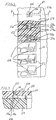
- the print cartridge 20 comprises a polymeric container 22, see Fig. 1, filled with ink and a printhead 24, see Figs. 2 and 3.
- the printhead 24 comprises a heater chip 50 having a plurality of resistive heating elements 52.
- the printhead 24 further includes a nozzle plate 54 having a plurality of openings 56 extending through it which define a plurality of nozzles 58 through which ink droplets are ejected.
- the diameter of each nozzle 58 is from about 15 microns to about 28 microns.
- the nozzle plate 54 may be formed from a flexible polymeric material substrate which is adhered to the heater chip 22 via an adhesive (not shown). Examples of polymeric materials from which the nozzle plate 54 may be formed and adhesives for securing the plate 54 to the heater chip 50 are set out in EP-A-0761448. As noted therein, the plate 54 may be formed from a polymeric material such as polyimide, polyester, fluorocarbon polymer, or polycarbonate, which is preferably about 15 to about 200 microns thick, and most preferably about 50 to about 125 microns thick. Examples of commercially available plate materials include a polyimide material available from E.I. DuPont de Nemours & Co. under the trademark "KAPTON” and a polyimide material available from Ube (of Japan) under the trademark "UPILEX.”
- the plate 54 may be bonded to the chip 50 via any art recognized technique, including a thermocompression bonding process.
- sections 54a of the plate 54 and portions 50a of the heater chip 50 define a plurality of bubble chambers 55.
- Ink supplied by the container 22 flows into the bubble chambers 55 through ink supply channels 55a.
- the resistive heating elements 52 are positioned on the heater chip 50 such that each bubble chamber 55 has only one heating element 52.
- Each bubble chamber 55 communicates with one nozzle 58, see Fig. 3.
- the resistive heating elements 52 are individually addressed by voltage pulses provided by a driver circuit 300, see Fig. 7. Each voltage pulse is applied to one of the heating elements 52 to momentarily vaporize the ink in contact with that heating element 52 to form a bubble within the bubble chamber 55 in which the heating element 52 is found.
- the function of the bubble is to displace ink within the bubble chamber 55 such that a droplet of ink is expelled from a nozzle 58 associated with the bubble chamber 55.
- a flexible circuit (not shown) secured to the polymeric container 22 is used to provide a path for energy pulses to travel from the driver circuit 300 to the heater chip 50.
- Bond pads (not shown) on the heater chip 50 are bonded to end sections of traces (not shown) on the flexible circuit.
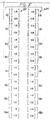
- the nozzle plate 54 is provided with a plurality of primary nozzles 110 and secondary nozzles 120, see Fig. 4.
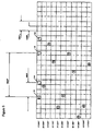
- there are eight segments IA-VIIIA of primary nozzles 110 each segment having 38 nozzles, as represented in Fig. 5.
- the total number of primary nozzles 110 in the illustrated embodiment, equals 304 nozzles.
- there are eight segments IB-VIIIB of secondary nozzles 120 each segment having 38 nozzles.
- the total number of secondary nozzles 120 equals 304 nozzles.
- the specific numbers of primary and secondary nozzles 110 and 120 formed on the nozzle plate 54 are mentioned herein for illustrative purposes only. Hence, the numbers of primary and secondary nozzles 110 and 120 are not intended to be limited to those represented in Fig. 5.
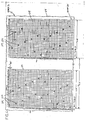
- the primary nozzles 110 include first and second nozzles 112 and 114 positioned in first and second nozzle plate columns 212 and 214, see Figs. 4 and 6.
- the secondary nozzles 120 include third and fourth nozzles 122 and 124 positioned in third and fourth nozzle plate columns 222 and 224, see Fig. 4. Front sections of the first and second columns 212 and 214 are spaced apart from one another by a distance equal to X/600 inch (X/24mm), wherein X is an odd integer ⁇ 3 and ⁇ 9, see Figs. 4 and 6. Front sections of the third and fourth columns 222 and 224 are spaced apart from one another by a distance equal to X/600 inch, wherein X is an odd integer ⁇ 3 and ⁇ 9, see Fig.
- Front sections of the first and third columns 212 and 222 are spaced apart from one another by a distance equal to Y/600 inch, wherein Y is an odd integer ⁇ 11, see Fig. 4.
- Y is an odd integer ⁇ 11, see Fig. 4.
- the first and second nozzles 112 and 114 of segment IA and the third and fourth nozzles 122 and 124 of segment IB are represented in Fig. 4 by solid dots with numbers positioned adjacent to the dots.
- the first and second nozzles 112 and 114 of segment IA and two nozzles of segment IIA are illustrated in Fig. 6 by numbered circles.
- the first nozzles 112 are represented by odd-numbered circles and the second nozzles 114 are represented by even-numbered circles.
- the 38 nozzles of each of segments IA and IB are numbered 1-19 and 2-20 in Figs. 4-6.
- the vertical distance between center points of adjacent first and second nozzles 112 and 114 positioned in adjacent horizontal rows in the columns 212 and 214, e.g., nozzles 1 and 6 located in rows 1 and 2, is approximately 1/600 (1/24mm) inch, see Figs. 4 and 6.
- the vertical distance between center points of adjacent third and fourth nozzles 122 and 124 positioned in adjacent horizontal rows in the third and fourth columns 222 and 224, e.g., nozzles 1 and 6, is also about 1/600 inch, see Fig. 4.
- the vertical distance between center points of vertically adjacent first nozzles 112, e.g., nozzles 1 and 11, is approximately 1/300 inch (0.085mm or 1/12mm).
- the vertical distance between vertically adjacent second nozzles 114, third nozzles 122 and fourth nozzles 124 is approximately 1/300 inch.
- the numbers adjacent to the dots in Fig. 4 and within the circles in Fig. 6 designate vertical subcolumns within the nozzle plate columns 212 and 214 in which center points of the nozzles 112 and 114 are found.
- the width of each vertical subcolumn within each of the nozzle plate columns 212 and 214 is 1/14,400 inch (1/567mm).
- the horizontal distance between the center points of two horizontally adjacent first nozzles 112, e.g., nozzles 1 and 3 is approximately 2/14,400 inch.
- the horizontal distance between the center points of two horizontally adjacent second nozzles 114, e.g., nozzles 2 and 4 is approximately 2/14,400 inch.
- the 38 nozzles of each of segments IIA-VIIIA and segments IB-VIIIB are arranged in the same order and are spaced from one another in the same manner as are the 38 nozzles of segment IA.
- the secondary nozzles 120 are arranged in the same order and spaced from one another in the same manner as the primary nozzles 110. Accordingly, the order and spacing of the secondary nozzles 120 will not be further described herein.
- the driver circuit 300 comprises a microprocessor 310, an application specific integrated circuit (ASIC) 320, a primary nozzle/secondary nozzle select circuit 330, decoder circuitry 340 and a common drive circuit 350.
- ASIC application specific integrated circuit
- the primary nozzle/secondary nozzle select circuit 330 selectively enables one or both of the primary nozzle segments IA-VIIIA and the secondary nozzle segments IB-VIIIB. It has a first output 330a which is electrically coupled to the primary nozzles 110 via conductor 330b. It also has a second output 330c which is electrically coupled to the secondary nozzles 120 via a conductor 330d. Thus, a first select signal present at the first output 330a is used to select the operation of the primary nozzles 110 while a second select signal present at the second output 330c is used to select the operation of the secondary nozzles 120.
- the primary nozzle/secondary nozzle select circuit 330 is electrically coupled to the ASIC 320 and generates appropriate select signals in response to command signals received from the ASIC 320.
- resistive heating element 52 there is a single resistive heating element 52 associated with each of the primary and secondary nozzles 110 and 120.
- the illustrated resistive heating elements 52 are numbered and grouped so as to correspond with the nozzle numbering and segment groupings used in Figs. 4-6.
- the common drive circuit 350 comprises a plurality of drivers 352 which are electrically coupled to a power supply 400, the ASIC 320 and the resistive heating elements 52.
- sixteen drivers 352 are provided. Each of the sixteen drivers 352 is electrically coupled to one-half of the heating elements 52 associated with one of the primary nozzle segments IA-VIIIA and one-half of the heating elements 52 associated with one of the secondary nozzle segments IB-VIIIB.
- the first driver 352 i.e., the driver designated number 1 is coupled to the heating elements 52 associated with the upper one-half of the nozzles 110 of the primary nozzle segment IA, i.e., the nozzles numbered 1-19 in Figs.
- the second driver 352 i.e., the driver designated number 2 is coupled to the heating elements 52 associated with the lower one-half of the nozzles 110 of the primary nozzle segment IA, i.e., the nozzles numbered 2-20 in Figs. 4-6, and the heating elements 52 associated with the lower one-half of the nozzles 120 of the secondary nozzle segment IB.
- the fifteenth driver 352 i.e., the driver designated number 15, is coupled to the heating elements 52 associated with the upper one-half of the nozzles 110 of the primary nozzle segment VIIIA, and the heating elements 52 associated with the upper one-half of the nozzles 120 of the secondary nozzle segment VIIIB.
- Each address line 344 extends to heating elements 52 associated with like numbered nozzles in each of the primary and secondary segments IA-VIIIA and IB-VIIIB.
- the first address line 344 i.e., the address line numbered 1 in Fig. 7 is connected to the resistive heating elements 52 associated with the number 1 primary and secondary nozzles 110 and 120 in each of the primary and secondary segments IA-VIIIA and IB-VIIIB.
- the tenth address line 344 i.e., the address line numbered 10 in Fig.
- the twentieth address line 344 i.e., the address line numbered 20 in Fig. 7, is connected to the resistive heating elements 52 associated with the number 20 primary and secondary nozzles in each of the primary and secondary segments IA-VIIIA and IB-VIIIB.
- the ASIC 320 sends appropriate signals to the decoder circuitry 340 such that during a given firing cycle, the decoder circuitry 340 generates appropriate address signals to the heating elements 52 associated with the primary and secondary nozzles 110 and 120.
- Each driver 352 is only activated by the ASIC 320 when one of the heating elements 52 to which it is connected is to be fired.
- the specific heating elements 52 fired during a given firing cycle depends upon print data received by the microprocessor 310 from a separate processor (not shown) electrically coupled to it.
- the microprocessor 310 generates signals which are passed to the ASIC 320 and, in turn, the ASIC 320 generates appropriate firing signals which are passed to the sixteen drivers 352.
- the activated drivers 352 then apply firing voltage pulses to the heating elements 52 in conjunction with the ground path provided by the decoder circuitry 340.
- the first driver 352 will be activated simultaneously with the activation of the first output 330a of the select circuit 330 and the first address line 344. If the number 2 primary nozzle 110 in segment IA is not to be fired during a given normal speed mode firing cycle segment (the normal speed mode will be discussed below), the second driver 352 will not be fired when the first output 330a of the select circuit 330 and the second address line 344 are simultaneously activated. If the upper-most primary nozzle 110 numbered 10 in segment IA is to be fired, the first driver 352 will be fired when the first output 330a of the select circuit 330 and the tenth address line 344 are simultaneously activated.
- the second driver 352 will not be fired when the first output 330a of the select circuit 330 and the tenth address line 344 are simultaneously activated.
- the printing apparatus 10 is selectively operable in one of a normal mode of operation and a high speed mode of operation.
- the user of the apparatus 10 may select the desired mode via software during printer set up.
- FIG. 8 A timing diagram for the normal speed mode of operation is illustrated in Fig. 8, wherein an expanded normal speed mode firing cycle 500 is shown.
- the driver circuit 300 is capable of applying, depending upon print data received by the microprocessor 310 from the separate processor (not shown) electrically coupled to it, first firing pulses to first heating elements 52, i.e., the heating elements 52 associated with the first nozzles 112 (the odd-numbered primary nozzles), during a first segment 502a of each normal speed mode firing cycle, second firing pulses to second heating elements 52, i.e., the heating elements 52 associated with the second nozzles 114 (the even-numbered primary nozzles), during a second segment 502b of each normal speed mode firing cycle, third firing pulses to fourth heating elements 52, i.e., the heating elements 52 associated with the fourth nozzles 124 (the even-numbered secondary nozzles), during a third segment 502c of each normal speed mode firing cycle, and fourth firing pulses to third heating elements 52, i.e., the heating
- the ASIC 320 causes the decoder circuitry 340 to cycle through its odd address lines 344.
- the ASIC 320 causes the decoder circuitry 340 to cycle through its even address lines 344.
- the first output 330a is active only during the first and second segments 502a and 502b.
- the second output 330c is active only during the third and fourth segments 502c and 502d.
- the first output 330a is active and, depending upon the print data received by the microprocessor 310, the appropriate drivers 352 are activated as the decoder circuitry 340 cycles through its odd address lines 344 such that the desired first heating elements associated with the first nozzles 112 in segments IA-VIIIA are fired.
- the first output 330a is active and, depending upon the print data received by the microprocessor 310, the appropriate drivers 352 are activated as the decoder circuitry 340 cycles through its even address lines 344 such that the desired second heating elements 52 associated with the second nozzles 114 in segments IA-VIIIA are fired.
- the second output 330c is active and, depending upon the print data received by the microprocessor 310, the appropriate drivers 352 are activated as the decoder circuitry 340 cycles through its even address lines 344 such that the desired fourth heating elements 52 associated with the fourth nozzles 124 in segments IB-VIIIB are fired.
- the second output 330c is active and, depending upon the print data received by the microprocessor 310, the appropriate drivers 352 are activated as the decoder circuitry 340 cycles through its odd address lines 344 such that the desired third heating elements 52 associated with the third nozzles 122 in segments IB-VIIIB are fired.
- the length of time of each of the first, second, third and fourth segments 502a-502d of the normal speed mode firing cycle is from about 15 ⁇ seconds to about 25 ⁇ seconds.
- the printhead speed is from about 33.33 inches/second (0.85m/s) to about 55.56 inches/second (1.41m/s).
- the length of time of each of the segments 502a-502d is about 20.825 ⁇ seconds such that the total firing cycle time is approximately 83.3 ⁇ seconds.
- the printhead speed is about 40 inches/second (1.02m/s) such that the printhead travels approximately 1/300 inch per firing cycle.
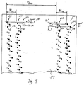
- a plot is illustrated showing dots generated by a first nozzle 112, a second nozzle 114, a third nozzle 122 and a fourth nozzle 124 during normal speed mode operation.
- the initial positions of the nozzles 112, 114, 122 and 124 are shown.
- the distance between the first and third nozzles 112 and 122 is 9/600 inch (9/24mm).
- Dots generated by the nozzles 112, 114, 122 and 124 are represented by numbered circles, wherein dots 1A are formed by the first nozzle 112, dots 2A are formed by the second nozzle 114, dots 1 B are formed by the third nozzle 122 and dots 2B are formed by the fourth nozzle 124.
- dots 1A are formed by the first nozzle 112
- dots 2A are formed by the second nozzle 114
- dots 1 B are formed by the third nozzle 122
- dots 2B are formed by the fourth nozzle 124.
- nozzle 112 is fired and the printhead moves a distance across the paper substrate 12 (from right to left) equal to 1/1200 (1/47mm)inch.
- nozzle 114 is fired and the printhead moves another 1/1200 inch across the paper substrate 12.
- the dot 2A created by the nozzle 114 is horizontally spaced approximately 5/1200 inch from the dot 1A created by the nozzle 112.
- nozzle 124 is fired and the printhead moves another 1/1200 inch across the paper substrate 12.
- nozzle 122 is fired and the printhead moves another 1/1200 inch across the paper substrate 12.
- the dot 2B created by nozzle 124 is horizontally spaced approximately 7/1200 inch from the dot 1B created by the nozzle 122.
- dot pairs 1A/1B and 2A/2B are in different 1/600 inch halves of the 1/300 inch windows. Thus, 600 dots per inch horizontal resolution occurs during normal speed mode printing.
- first and second columns 212 and 214 are spaced apart from one another by a distance equal to X/600 inch, wherein X is an odd integer; the third and fourth columns are spaced apart from one another by a distance equal to X/600 inch, wherein X is an odd integer; and the first and third columns are spaced apart from one another by a distance equal to Y/600 inch, wherein Y is an odd integer.
- FIG. 10 A timing diagram for the high speed mode of operation is illustrated in Fig. 10, wherein an expanded high speed mode firing cycle 600 is shown.
- the driver circuit 300 is capable of simultaneously applying, depending upon print data received by the microprocessor 310 from the separate processor (not shown) electrically coupled to it, first and third firing pulses to first and third heating elements 52, i.e., the heating elements 52 associated with the first and third nozzles 112 and 122, during a first segment 602a of each high speed mode firing cycle, and second and fourth firing pulses to second and fourth heating elements 52, i.e., the heating elements 52 associated with the second and fourth nozzles 114 and 124, during a second segment 602b of each high speed mode firing cycle.
- first and third firing pulses to first and third heating elements 52, i.e., the heating elements 52 associated with the first and third nozzles 112 and 122, during a first segment 602a of each high speed mode firing cycle
- second and fourth firing pulses to second and fourth heating elements 52,
- the ASIC 320 causes the decoder circuitry 340 to cycle through its odd address lines 344 such that the first and third heating elements associated with the first and third nozzles 112 and 122 in segments IA-VIIIA and IB-VIIIB are enabled.
- the ASIC 320 causes the decoder circuitry 340 to cycle through its even address lines 344 such that the second and fourth heating elements associated with the second and fourth nozzles 114 and 124 in segments IA-VIIIA and IB-VIIIB are enabled.
- the first and second outputs 330a and 330c are selectively enabled or activated during the first and second segments 602a and 602b.
- the two outputs 330a and 330c may be enabled simultaneously during the first segment 602a if both of a given pair of first and third heating elements are to be fired and may be enabled simultaneously during the second segment 602b if both of a given pair of second and fourth heating elements are to be fired. If only the first heating element of a given pair of heating elements 52 associated with a pair of first and third nozzles 112 and 122 is to be fired during the first segment 602a, only the first output 330a will be enabled. If only the third heating element 52 of a given pair of heating elements 52 associated with a pair of first and third nozzles 112 and 122 is to be fired, only the second output 330c will be enabled.
- the length of time of each of the first and second segments 602a and 602b of the high speed mode firing cycle is from about 15 ⁇ seconds to about 25 ⁇ seconds.
- the printhead speed is from about 66.66 inches/second (1.69m/s) to about 111.12 inches/second (2.82m/s).
- the length of time of each of the segments 602a and 602b is about 20.825 ⁇ seconds such that the total firing cycle time is approximately 41.65 ⁇ seconds.
- the printhead speed is about 80 inches/second such that the printhead travels approximately 1/300 inch per firing cycle.
- a plot is illustrated showing dots generated by a first nozzle 112, a second nozzle 114, a third nozzle 122 and a fourth nozzle 124 during high speed mode operation.
- the initial positions of the nozzles 112, 114, 122 and 124 are shown.
- Dots generated by the nozzles 112, 114, 122 and 124 are represented by numbered circles, wherein dots 1A are formed by the first nozzle 112, dots 2A are formed by the second nozzle 114, dots 1B are formed by the third nozzle 122 and dots 2B are formed by the fourth nozzle 124.
- dots 1A are formed by the first nozzle 112
- dots 2A are formed by the second nozzle 114
- dots 1B are formed by the third nozzle 122
- dots 2B are formed by the fourth nozzle 124.
- nozzles 112 and 122 are fired and the printhead moves a distance across the paper substrate 12 equal to 1/600 inch.
- nozzles 114 and 124 are fired and the printhead moves another 1/600 inch across the paper substrate 12.
- the dots created by the nozzles 112, 114, 122 and 124 are positioned on a 600 dots per inch horizontal grid.
- the primary and secondary nozzles 110 and 120 are tested to determine if they are operational. Nozzle testing takes place at a maintenance station 410 (also referred to herein as a nozzle testing station), see Figs. 1 and 12, located within the printing apparatus 10.
- the station 410 includes a conventional light-emitting diode (LED) light source 600 and a conventional light receiving photocell 602.
- the microprocessor 310 controls the operation of the light source 600 and the photocell 602.
- ink passing from the fired nozzle causes an interruption or blockage of all or a substantial portion of a beam of light 600a emitted from the light source 600.
- the interruption is detected by the photocell 602 which, in response, generates an ink-sensed signal to the microprocessor 310.
- the diameter of the light beam 600a is preferably from about 1/600 inch to about 1/150 inch.
- the remaining structure forming the maintenance station 410 may be constructed as set out in commonly assigned U.S. Patent Nos. 5,563,637, 5,612,722 and 5,627,572.
- the maintenance station 410 includes a bi-directional drive motor 430 driving a worm gear 432 that meshes with a gear 434, see Fig. 12.
- a drive screw 436 is mounted on the same shaft as the gear 434 and carries a drive nut 438.
- the worm gear 432 is driven in one direction or the other so as to rotate the drive screw 436.
- the drive nut 438 moves upward or downward.
- the drive nut 438 has two forked arms 438a (only one is shown in Fig. 12), extending outwardly therefrom.
- the forked arms 438a engage two projections 440 (only one is shown in Fig. 12) provided on opposite sides of a rocker frame 442.
- the frame 442 is pivotally supported by pivots extending into holes 444 in opposing sides 446 of a maintenance station frame 448 so that as the drive nut 438 is moved up or down the rocker frame 442 pivots about the axes of the holes 444.
- the rocker frame 442 has two slots 442a and 442b on one side and two similar slots on an opposite side.
- a cup-like cap 450 is mounted on a cap support having two projections 452 extending into the slots 442b.
- the cap support is slidably mounted for vertical movement along a post (not shown) extending upwardly from a base 448a of the station frame 448.
- a wiper 460 is mounted on a spit cup 462 and the spit cup 462 is mounted on a support (not shown) having projections extending into the slots 442a.
- the arrangement is such that as the rocker frame 442 tilts clockwise, as viewed in Fig. 12, the cup 450 is lowered and the wiper 460 is raised, and as the rocker frame 442 tilts counter-clockwise the cup 450 is raised and the wiper 460 is lowered.
- the maintenance station 410 and the printhead 24 are disposed on opposite sides of a plane in which the paper substrate 12 is fed past the printhead 24, with the top surface of the maintenance station 410 slightly below and preferably to one side of the paper feed path.
- the motor 430 moves the rocker frame 442 between three operative positions: a wiper active position where the wiper 460 extends, e.g., 0.5mm, above the path traversed by the nozzle plate 54 so that the wiper 460 engages the nozzle plate outer surface as the printhead 24 is moved past the wiper 460 by the print cartridge drive mechanism 44; a cap active position where the cap 450 presses against the nozzle plate outer surface when the printhead 24 is positioned over the cap 450 to form a closed environment around the nozzles 110 and 120; and an inactive position where the cap 450 and the wiper 460 are positioned below the paper feed path and are in inactive positions.
- nozzle testing which may occur before, during and/or after a print job, is effected in the following manner.
- the printhead 24 is moved horizontally via the print cartridge drive mechanism 44 so that it passes over the beam of light 600a emitted from the light source 600.
- the beam of light 600a extends over a portion of the spit cup 462.
- the wiper 460 may be in its active position, as illustrated in Fig. 12, or it may be in its inactive position, i.e., the position where both the cap 450 and the wiper 460 are located in inactive positions. It may be beneficial for the wiper 460 to be in its inactive position as the printhead 24 will make multiple passes over the spit cup 462 during nozzle testing.
- the drive mechanism 44 is capable of moving the print cartridge 20 in increments of about 1/600 inch.
- the diameter of the light beam 600a is from about 1/600 inch to about 1/150 inch. Because the drive mechanism 44 in the illustrated embodiment cannot move the printhead 24 in increments of less than about 1/600 inch, the light beam has a diameter of about 1/300 inch and it is preferred that the ink droplets pass through the center of the light beam 600a so as to maximize the likelihood that detection will occur, the nozzles 110 and 120 are tested while the printhead 24 is moving over the stationary light beam 600a.
- the microprocessor 310 effects the firing of the heating elements 52 associated with one-half of the nozzles 110 of one of the primary nozzle segments IA-VIIIA and the heating elements associated with one-half of the nozzles 120 of one of the secondary nozzle segments IB-VIIIB.
- the first, second, third and fourth nozzles 112, 114, 122 and 124 are positioned respectively in first, second, third and fourth nozzle plate columns 212, 214, 222 and 224. Further, center points of the nozzles 112, 114, 122 and 124 are located in subcolumns within the nozzle plate columns 212, 214, 222 and 224.
- the heating element 52 associated with one of the nozzles located in that subcolumn is fired.
- the specific heating element 52 fired is the one associated with the nozzle that is found in a segment half currently being tested.
- the heating element 52 associated with the nozzle 112 located in the upper half of segment IA and in subcolumn 1 of the first column 212 is fired first. This is because subcolumn 1 of the first column 212 will be the first subcolumn to be positioned over the light beam 600a as the printhead 24 moves over the beam 600a and the spit cup 462.
- the heating element 52 associated with the nozzle 112 located in the upper half of segment IA and in the third subcolumn in column 212 is fired next.
- the heating elements associated with the remaining upper-most first nozzles 112 in segment IA are sequentially fired as their nozzles 112 move over the light beam 600a.
- the heating elements 52 associated with the upper-most second nozzles 114 in segment IA are sequentially fired as the second nozzles 114 pass over the light beam 600a, followed by the firing of the heating elements 52 associated with the upper-most third and fourth nozzles 122 and 124 of segment IB.
- Sixteen passes of the printhead 24 are required to effect the testing of each of the nozzles 110 and 120 in the illustrated embodiment.
- the heating element firing sequence during nozzles testing may be varied from that which is described above.
- an ink droplet is ejected from its associated nozzle.
- the ink droplet passes through the beam of light 660a and causes an interruption or blockage of the light beam 660a.
- the photocell 602 senses interruptions in the beam of light 660a resulting from ink droplets passing through the beam of light 660a.
- the photocell 602 Upon sensing an interruption in the beam of light 660a, the photocell 602 generates an ink-detected signal which is received by the microprocessor 310. If an ink droplet is not sensed by the photocell 602 after the heating element of a given nozzle is fired during nozzle testing, the microprocessor 310 designates that nozzle defective.
- the microprocessor 310 causes the heating element 52 associated with the other of the pair of nozzles 110 and 120, assuming the other nozzle is operable, to operate in the place of the heating element of the one defective nozzle during normal mode operation.
- the other nozzle and its associated heating element 52 perform double duty during normal mode operation.
- An ink-absorbent pad 448b is located over the base 448a of the station frame 448 and functions to absorb ejected ink.
- Another ink-absorbent pad (not shown) is located in the spit cup 462 and serves to absorb ink ejected during nozzle testing.
Abstract
Description
- This invention relates to ink jet printing apparatuses.
- Drop-on-demand ink jet printers form a printed image by printing a pattern of individual dots or pixels on a print medium, such as a sheet of paper. The possible locations for the dots can be represented by an array or grid of pixels or square areas arranged in a rectilinear array of rows and columns wherein the center to center distance or dot pitch between pixels is determined by the resolution of the printer. The dots are printed as a printhead moves across the medium in a line scan direction. Between line scans, a stepper motor moves the print medium in a direction transverse to the line scan direction.
- Drop-on-demand ink jet printers use thermal energy to produce a vapor bubble in an ink-filled chamber to expel a droplet. A thermal energy generator or heating element, usually a resistor, is located in the chamber on a heater chip near a discharge nozzle. A plurality of chambers, each provided with a single heating element, are provided in the printer's printhead. The printhead typically comprises the heater chip and a nozzle plate having a plurality of the discharge nozzles formed therein. The printhead forms part of an ink jet print cartridge which also comprises an ink-filled container.
- In one conventional printhead, discharge nozzles are arranged in two columns, with the nozzles of one column staggered relative to the nozzles of the other column. During use, the two columns function as a single column. Hence, each horizontal row of dots is printed by only a single nozzle. If a nozzle fails, the printed document will include horizontal blank lines where ink is absent due to the defective nozzle not printing dots along those lines.
- Printer manufacturers are constantly searching for techniques which may be used to improve printing speed. One known technique involves adding additional nozzles to each nozzle column on the printhead. However, as nozzle column length increases, proper nozzle alignment along the columns becomes more critical. This is because print misalignment resulting from nozzle misalignment becomes more noticeable as nozzle column length increases.
- An improved printhead which allows for increased printing speed and improved print quality is desired.
- In accordance with the present invention, an ink jet printing apparatus is provided having a printhead with a plurality of primary and secondary nozzles. The primary nozzles preferably include first and second nozzles positioned in first and second nozzle plate columns. The secondary nozzles preferably include third and fourth nozzles positioned in third and fourth nozzle plate columns. The secondary nozzles define redundant nozzles. That is, each secondary nozzle shares a horizontal axis with a primary nozzle. A device located in a nozzle testing station detects ejected ink from a fired nozzle.
- In the preferred embodiment, instead of having two columns of nozzles, which function as a single vertical line of nozzles, printing a swath of data during a single pass of the printhead, there are four columns of nozzles, which function as two vertical lines of nozzles, printing the data. Each vertical line of nozzles is capable of printing approximately one-half of the pixels printed during a given pass of the printhead across the print medium. The printer is selectively operable in one of a normal mode of operation and a high speed mode of operation. During normal mode operation, the heating elements associated with the first nozzles are fired during a first segment of a firing cycle, the heating elements associated with the second nozzles are fired during a second segment of the firing cycle, the heating elements associated with the fourth nozzles are fired during a third segment of the firing cycle, and the heating elements associated with the third nozzles are fired during a fourth segment of the firing cycle. During high speed mode operation, the heating elements associated with the first and third nozzles are fired during a first segment of a high speed mode firing cycle and the heating elements associated with the second and fourth nozzles are fired during a second segment of the high speed mode firing cycle. Due to the redundant nozzles, the printer may be operated at an increased speed.
- It is a further feature that the printer is provided with a nozzle testing station. There, each nozzle is tested to determine if it is operable. If not, its associated nozzle found on the same horizontal line preferably does double duty during normal speed operation. Hence, if a nozzle fails and its associated nozzle is operable, all of the data to be printed by the nozzle pair will be printed during normal mode operation.
- By adding redundant nozzles, nozzle column length has not been substantially increased. This is an advantage as print misalignment resulting from nozzle misalignment becomes more noticeable as nozzle column length increases.
- An embodiment of the invention will now be described by way of example only and with reference to the drawings.
-
- Fig. 1 is a perspective view of an ink jet printing apparatus having a print cartridge constructed in accordance with the present invention;
- Fig. 2 is a view of a portion of a heater chip coupled to an nozzle plate with sections of the nozzle plate removed at two different levels;
- Fig. 3 is a view taken along section line 3-3 in Fig. 2;
- Fig. 4 is a schematic illustration of a portion of a nozzle plate with first and second nozzles of segment IA and third and fourth nozzles of segment IB represented by solid dots;
- Fig. 5 is an illustration of a nozzle plate with primary and secondary nozzles of segments IA-VIIIA and segments IB-VIIIB numerically designated;
- Fig. 6 is an illustration of a portion of a nozzle plate with first and second nozzles of segment IA and two nozzles of segment IIA represented by numbered circles;
- Fig. 7 is a schematic diagram illustrating a driver circuit;
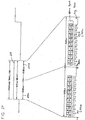
- Fig. 8 is a timing diagram for normal speed mode operation;
- Fig. 9 is a plot showing dots generated by first, second, fourth and third nozzles during consecutive segments of normal speed mode firing cycles;
- Fig. 10 is a timing diagram for high speed mode operation;
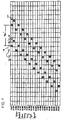
- Fig. 11 is a plot showing dots generated by first, second, third and fourth nozzles during consecutive segments of high speed mode firing cycles; and
- Fig. 12 is a perspective view of a maintenance station of the apparatus of the present invention.
-
- Referring now to Fig. 1, there is shown an ink
jet printing apparatus 10 having aprint cartridge 20 constructed in accordance with the present invention. Thecartridge 20 is supported in acarrier 40 which, in turn, is slidably supported on aguide rail 42. A printcartridge drive mechanism 44 is provided for effecting reciprocating movement of thecarrier 40 back and forth along theguide rail 42. Thedrive mechanism 44 includes amotor 44a with a drive pulley 44b and a drive belt 44c which extends about the drive pulley 44b and anidler pulley 44d. Thecarrier 40 is fixedly connected to the drive belt 44c so as to move with the drive belt 44c. Operation of themotor 44a effects back and forth movement of the drive belt 44c and, hence, back and forth movement of thecarrier 40 and theprint cartridge 20. As theprint cartridge 20 moves back and forth, it ejects ink droplets onto apaper substrate 12 provided below it.Driven rollers 14 mounted on ashaft 16 cooperate withpressure rollers 18 to advance thepaper substrate 12 in a direction generally orthogonal to the direction of print cartridge movement. Theshaft 16 is driven by astepper motor assembly 19. - The
print cartridge 20 comprises apolymeric container 22, see Fig. 1, filled with ink and aprinthead 24, see Figs. 2 and 3. Theprinthead 24 comprises aheater chip 50 having a plurality ofresistive heating elements 52. Theprinthead 24 further includes anozzle plate 54 having a plurality ofopenings 56 extending through it which define a plurality ofnozzles 58 through which ink droplets are ejected. The diameter of eachnozzle 58 is from about 15 microns to about 28 microns. - The
nozzle plate 54 may be formed from a flexible polymeric material substrate which is adhered to theheater chip 22 via an adhesive (not shown). Examples of polymeric materials from which thenozzle plate 54 may be formed and adhesives for securing theplate 54 to theheater chip 50 are set out in EP-A-0761448. As noted therein, theplate 54 may be formed from a polymeric material such as polyimide, polyester, fluorocarbon polymer, or polycarbonate, which is preferably about 15 to about 200 microns thick, and most preferably about 50 to about 125 microns thick. Examples of commercially available plate materials include a polyimide material available from E.I. DuPont de Nemours & Co. under the trademark "KAPTON" and a polyimide material available from Ube (of Japan) under the trademark "UPILEX." - The
plate 54 may be bonded to thechip 50 via any art recognized technique, including a thermocompression bonding process. When theplate 54 and theheater chip 50 are joined together,sections 54a of theplate 54 andportions 50a of theheater chip 50 define a plurality ofbubble chambers 55. Ink supplied by thecontainer 22 flows into thebubble chambers 55 throughink supply channels 55a. Theresistive heating elements 52 are positioned on theheater chip 50 such that eachbubble chamber 55 has only oneheating element 52. Eachbubble chamber 55 communicates with onenozzle 58, see Fig. 3. - The
resistive heating elements 52 are individually addressed by voltage pulses provided by adriver circuit 300, see Fig. 7. Each voltage pulse is applied to one of theheating elements 52 to momentarily vaporize the ink in contact with thatheating element 52 to form a bubble within thebubble chamber 55 in which theheating element 52 is found. The function of the bubble is to displace ink within thebubble chamber 55 such that a droplet of ink is expelled from anozzle 58 associated with thebubble chamber 55. - A flexible circuit (not shown) secured to the
polymeric container 22 is used to provide a path for energy pulses to travel from thedriver circuit 300 to theheater chip 50. Bond pads (not shown) on theheater chip 50 are bonded to end sections of traces (not shown) on the flexible circuit. Current flows from thecircuit 300 to the traces on the flexible circuit and from the traces to the bond pads on theheater chip 50. The current then flows from the bond pads alongconductors 53 to theheating elements 52. - In accordance with the present invention, the
nozzle plate 54 is provided with a plurality ofprimary nozzles 110 andsecondary nozzles 120, see Fig. 4. In the illustrated embodiment, there are eight segments IA-VIIIA ofprimary nozzles 110, each segment having 38 nozzles, as represented in Fig. 5. Thus, the total number ofprimary nozzles 110, in the illustrated embodiment, equals 304 nozzles. Similarly, there are eight segments IB-VIIIB ofsecondary nozzles 120, each segment having 38 nozzles. The total number ofsecondary nozzles 120 equals 304 nozzles. The specific numbers of primary andsecondary nozzles nozzle plate 54 are mentioned herein for illustrative purposes only. Hence, the numbers of primary andsecondary nozzles - The
primary nozzles 110 include first andsecond nozzles nozzle plate columns secondary nozzles 120 include third andfourth nozzles nozzle plate columns 222 and 224, see Fig. 4. Front sections of the first andsecond columns fourth columns 222 and 224 are spaced apart from one another by a distance equal to X/600 inch, wherein X is an odd integer ≥ 3 and ≤ 9, see Fig. 4. Front sections of the first andthird columns - The first and
second nozzles fourth nozzles second nozzles first nozzles 112 are represented by odd-numbered circles and thesecond nozzles 114 are represented by even-numbered circles. The 38 nozzles of each of segments IA and IB are numbered 1-19 and 2-20 in Figs. 4-6. - The vertical distance between center points of adjacent first and
second nozzles columns nozzles rows fourth nozzles fourth columns 222 and 224, e.g.,nozzles first nozzles 112, e.g.,nozzles second nozzles 114,third nozzles 122 andfourth nozzles 124 is approximately 1/300 inch. - The numbers adjacent to the dots in Fig. 4 and within the circles in Fig. 6 designate vertical subcolumns within the
nozzle plate columns nozzles nozzle plate columns first nozzles 112, e.g.,nozzles second nozzles 114, e.g.,nozzles - In the illustrated embodiment, the 38 nozzles of each of segments IIA-VIIIA and segments IB-VIIIB are arranged in the same order and are spaced from one another in the same manner as are the 38 nozzles of segment IA. Thus, the
secondary nozzles 120 are arranged in the same order and spaced from one another in the same manner as theprimary nozzles 110. Accordingly, the order and spacing of thesecondary nozzles 120 will not be further described herein. - The
driver circuit 300 comprises amicroprocessor 310, an application specific integrated circuit (ASIC) 320, a primary nozzle/secondary nozzleselect circuit 330,decoder circuitry 340 and acommon drive circuit 350. - The primary nozzle/secondary nozzle
select circuit 330 selectively enables one or both of the primary nozzle segments IA-VIIIA and the secondary nozzle segments IB-VIIIB. It has a first output 330a which is electrically coupled to theprimary nozzles 110 via conductor 330b. It also has a second output 330c which is electrically coupled to thesecondary nozzles 120 via aconductor 330d. Thus, a first select signal present at the first output 330a is used to select the operation of theprimary nozzles 110 while a second select signal present at the second output 330c is used to select the operation of thesecondary nozzles 120. The primary nozzle/secondary nozzleselect circuit 330 is electrically coupled to theASIC 320 and generates appropriate select signals in response to command signals received from theASIC 320. - As noted above, there is a single
resistive heating element 52 associated with each of the primary andsecondary nozzles resistive heating elements 52 are numbered and grouped so as to correspond with the nozzle numbering and segment groupings used in Figs. 4-6. - The
common drive circuit 350 comprises a plurality ofdrivers 352 which are electrically coupled to apower supply 400, theASIC 320 and theresistive heating elements 52. In the illustrated embodiment, sixteendrivers 352 are provided. Each of the sixteendrivers 352 is electrically coupled to one-half of theheating elements 52 associated with one of the primary nozzle segments IA-VIIIA and one-half of theheating elements 52 associated with one of the secondary nozzle segments IB-VIIIB. In Fig. 7, thefirst driver 352, i.e., the driver designatednumber 1, is coupled to theheating elements 52 associated with the upper one-half of thenozzles 110 of the primary nozzle segment IA, i.e., the nozzles numbered 1-19 in Figs. 4-6, and theheating elements 52 associated with the upper one-half of thenozzles 120 of the secondary nozzle segment IB. Thesecond driver 352, i.e., the driver designatednumber 2, is coupled to theheating elements 52 associated with the lower one-half of thenozzles 110 of the primary nozzle segment IA, i.e., the nozzles numbered 2-20 in Figs. 4-6, and theheating elements 52 associated with the lower one-half of thenozzles 120 of the secondary nozzle segment IB. Thefifteenth driver 352, i.e., the driver designatednumber 15, is coupled to theheating elements 52 associated with the upper one-half of thenozzles 110 of the primary nozzle segment VIIIA, and theheating elements 52 associated with the upper one-half of thenozzles 120 of the secondary nozzle segment VIIIB. Thesixteenth driver 352, i.e., the driver numbered 16, is coupled to theheating elements 52 associated with the lower one-half of thenozzles 110 of the primary nozzle segment VIIIA, and theheating elements 52 associated with the lower one-half of thenozzles 120 of the secondary nozzle segment VIIIB. - There are five
input lines 342 extending from theASIC 320 to thedecoder circuitry 340. Twentyaddress lines 344 extend from thedecoder circuitry 340 to theresistive heating elements 52. Eachaddress line 344 extends toheating elements 52 associated with like numbered nozzles in each of the primary and secondary segments IA-VIIIA and IB-VIIIB. For example, thefirst address line 344, i.e., the address line numbered 1 in Fig. 7, is connected to theresistive heating elements 52 associated with thenumber 1 primary andsecondary nozzles tenth address line 344, i.e., the address line numbered 10 in Fig. 7, is connected to theresistive heating elements 52 associated with thenumber 10 primary and secondary nozzles in each of the primary and secondary segments IA-VIIIA and IB-VIIIB. Thetwentieth address line 344, i.e., the address line numbered 20 in Fig. 7, is connected to theresistive heating elements 52 associated with thenumber 20 primary and secondary nozzles in each of the primary and secondary segments IA-VIIIA and IB-VIIIB. As will be discussed more explicitly below, theASIC 320 sends appropriate signals to thedecoder circuitry 340 such that during a given firing cycle, thedecoder circuitry 340 generates appropriate address signals to theheating elements 52 associated with the primary andsecondary nozzles - Each
driver 352 is only activated by theASIC 320 when one of theheating elements 52 to which it is connected is to be fired. Thespecific heating elements 52 fired during a given firing cycle depends upon print data received by themicroprocessor 310 from a separate processor (not shown) electrically coupled to it. Themicroprocessor 310 generates signals which are passed to theASIC 320 and, in turn, theASIC 320 generates appropriate firing signals which are passed to the sixteendrivers 352. The activateddrivers 352 then apply firing voltage pulses to theheating elements 52 in conjunction with the ground path provided by thedecoder circuitry 340. - If the heating element associated with the
number 1primary nozzle 110 in segment IA is to be fired during a given firing cycle segment, thefirst driver 352 will be activated simultaneously with the activation of the first output 330a of theselect circuit 330 and thefirst address line 344. If thenumber 2primary nozzle 110 in segment IA is not to be fired during a given normal speed mode firing cycle segment (the normal speed mode will be discussed below), thesecond driver 352 will not be fired when the first output 330a of theselect circuit 330 and thesecond address line 344 are simultaneously activated. If the upper-mostprimary nozzle 110 numbered 10 in segment IA is to be fired, thefirst driver 352 will be fired when the first output 330a of theselect circuit 330 and thetenth address line 344 are simultaneously activated. If the lower-mostprimary nozzle 110 numbered 10 in segment IA is not to be fired during a given normal speed mode firing cycle segment, thesecond driver 352 will not be fired when the first output 330a of theselect circuit 330 and thetenth address line 344 are simultaneously activated. - The
printing apparatus 10 is selectively operable in one of a normal mode of operation and a high speed mode of operation. The user of theapparatus 10 may select the desired mode via software during printer set up. - A timing diagram for the normal speed mode of operation is illustrated in Fig. 8, wherein an expanded normal speed
mode firing cycle 500 is shown. Thedriver circuit 300 is capable of applying, depending upon print data received by themicroprocessor 310 from the separate processor (not shown) electrically coupled to it, first firing pulses tofirst heating elements 52, i.e., theheating elements 52 associated with the first nozzles 112 (the odd-numbered primary nozzles), during afirst segment 502a of each normal speed mode firing cycle, second firing pulses tosecond heating elements 52, i.e., theheating elements 52 associated with the second nozzles 114 (the even-numbered primary nozzles), during a second segment 502b of each normal speed mode firing cycle, third firing pulses tofourth heating elements 52, i.e., theheating elements 52 associated with the fourth nozzles 124 (the even-numbered secondary nozzles), during a third segment 502c of each normal speed mode firing cycle, and fourth firing pulses tothird heating elements 52, i.e., theheating elements 52 associated with the third nozzles 122 (the odd-numbered secondary nozzles), during a fourth segment 502d of each normal speed mode firing cycle. - As illustrated in Fig. 8, during the first and
fourth segments 502a and 502d of each normal speed mode firing cycle, theASIC 320 causes thedecoder circuitry 340 to cycle through its odd address lines 344. During the second and third segments 502b and 502c of each normal speed mode firing cycle, theASIC 320 causes thedecoder circuitry 340 to cycle through its even address lines 344. The first output 330a is active only during the first andsecond segments 502a and 502b. The second output 330c is active only during the third and fourth segments 502c and 502d. - During the
first segment 502a of the normal speed mode firing cycle, the first output 330a is active and, depending upon the print data received by themicroprocessor 310, theappropriate drivers 352 are activated as thedecoder circuitry 340 cycles through itsodd address lines 344 such that the desired first heating elements associated with thefirst nozzles 112 in segments IA-VIIIA are fired. During the second segment 502b of the normal speed mode firing cycle, the first output 330a is active and, depending upon the print data received by themicroprocessor 310, theappropriate drivers 352 are activated as thedecoder circuitry 340 cycles through itseven address lines 344 such that the desiredsecond heating elements 52 associated with thesecond nozzles 114 in segments IA-VIIIA are fired. During the third segment 502c of the normal speed mode firing cycle, the second output 330c is active and, depending upon the print data received by themicroprocessor 310, theappropriate drivers 352 are activated as thedecoder circuitry 340 cycles through itseven address lines 344 such that the desiredfourth heating elements 52 associated with thefourth nozzles 124 in segments IB-VIIIB are fired. During the fourth segment 502d of the normal speed mode firing cycle, the second output 330c is active and, depending upon the print data received by themicroprocessor 310, theappropriate drivers 352 are activated as thedecoder circuitry 340 cycles through itsodd address lines 344 such that the desiredthird heating elements 52 associated with thethird nozzles 122 in segments IB-VIIIB are fired. - The length of time of each of the first, second, third and
fourth segments 502a-502d of the normal speed mode firing cycle is from about 15 µseconds to about 25 µseconds. The printhead speed is from about 33.33 inches/second (0.85m/s) to about 55.56 inches/second (1.41m/s). In the illustrated embodiment, the length of time of each of thesegments 502a-502d is about 20.825 µseconds such that the total firing cycle time is approximately 83.3 µseconds. Further, the printhead speed is about 40 inches/second (1.02m/s) such that the printhead travels approximately 1/300 inch per firing cycle. - It is noted that at the beginning of each of the second and third segments 502b and 502c of the normal speed mode firing cycle, a delay of about .868 µseconds occurs before the
heating element 52 associated with thenumber 2second nozzle 114 and thenumber 2fourth nozzle 124 are fired. - In Fig. 9, a plot is illustrated showing dots generated by a
first nozzle 112, asecond nozzle 114, athird nozzle 122 and afourth nozzle 124 during normal speed mode operation. The initial positions of thenozzles third nozzles nozzles first nozzle 112,dots 2A are formed by thesecond nozzle 114, dots 1 B are formed by thethird nozzle 122 and dots 2B are formed by thefourth nozzle 124. As can be seen from Fig. 9, during afirst segment 502a of a first normal speed mode firing cycle,nozzle 112 is fired and the printhead moves a distance across the paper substrate 12 (from right to left) equal to 1/1200 (1/47mm)inch. During a second segment 502b of the first normal speed mode firing cycle,nozzle 114 is fired and the printhead moves another 1/1200 inch across thepaper substrate 12. Thedot 2A created by thenozzle 114 is horizontally spaced approximately 5/1200 inch from the dot 1A created by thenozzle 112. During a third segment 502c of the first normal speed firing cycle,nozzle 124 is fired and the printhead moves another 1/1200 inch across thepaper substrate 12. During a fourth segment 502d of the first normal speed firing cycle,nozzle 122 is fired and the printhead moves another 1/1200 inch across thepaper substrate 12. The dot 2B created bynozzle 124 is horizontally spaced approximately 7/1200 inch from the dot 1B created by thenozzle 122. As is apparent from Fig. 9, dot pairs 1A/1B and 2A/2B are in different 1/600 inch halves of the 1/300 inch windows. Thus, 600 dots per inch horizontal resolution occurs during normal speed mode printing. This results because the first andsecond columns - A timing diagram for the high speed mode of operation is illustrated in Fig. 10, wherein an expanded high speed
mode firing cycle 600 is shown. Thedriver circuit 300 is capable of simultaneously applying, depending upon print data received by themicroprocessor 310 from the separate processor (not shown) electrically coupled to it, first and third firing pulses to first andthird heating elements 52, i.e., theheating elements 52 associated with the first andthird nozzles first segment 602a of each high speed mode firing cycle, and second and fourth firing pulses to second andfourth heating elements 52, i.e., theheating elements 52 associated with the second andfourth nozzles - During the
first segment 602a of the high speed mode firing cycle, theASIC 320 causes thedecoder circuitry 340 to cycle through itsodd address lines 344 such that the first and third heating elements associated with the first andthird nozzles ASIC 320 causes thedecoder circuitry 340 to cycle through itseven address lines 344 such that the second and fourth heating elements associated with the second andfourth nozzles second segments 602a and 602b. For example, the two outputs 330a and 330c may be enabled simultaneously during thefirst segment 602a if both of a given pair of first and third heating elements are to be fired and may be enabled simultaneously during the second segment 602b if both of a given pair of second and fourth heating elements are to be fired. If only the first heating element of a given pair ofheating elements 52 associated with a pair of first andthird nozzles first segment 602a, only the first output 330a will be enabled. If only thethird heating element 52 of a given pair ofheating elements 52 associated with a pair of first andthird nozzles heating elements 52 associated with a pair of second andfourth nozzles fourth heating element 52 is to be fired, only the second output 330c will be enabled. - The length of time of each of the first and
second segments 602a and 602b of the high speed mode firing cycle is from about 15 µseconds to about 25 µseconds. The printhead speed is from about 66.66 inches/second (1.69m/s) to about 111.12 inches/second (2.82m/s). In the illustrated embodiment, the length of time of each of thesegments 602a and 602b is about 20.825 µseconds such that the total firing cycle time is approximately 41.65 µseconds. Further, the printhead speed is about 80 inches/second such that the printhead travels approximately 1/300 inch per firing cycle. Additionally, at the beginning of the second segment 602b, there is a delay of about .868 µseconds before the heating elements associated with thenumber 2 andnumber 4 nozzles are fired. - In Fig. 11, a plot is illustrated showing dots generated by a
first nozzle 112, asecond nozzle 114, athird nozzle 122 and afourth nozzle 124 during high speed mode operation. The initial positions of thenozzles nozzles first nozzle 112,dots 2A are formed by thesecond nozzle 114, dots 1B are formed by thethird nozzle 122 and dots 2B are formed by thefourth nozzle 124. As can be seen from Fig. 11, during afirst segment 602a of a high speed mode firing cycle,nozzles paper substrate 12 equal to 1/600 inch. During a second segment 602b of the normal speed mode firing cycle,nozzles paper substrate 12. As is apparent from Fig. 11, the dots created by thenozzles - At an appropriate time during operation of the
printing apparatus 10, the primary andsecondary nozzles printing apparatus 10. As will be discussed more explicitly below, thestation 410 includes a conventional light-emitting diode (LED)light source 600 and a conventionallight receiving photocell 602. Themicroprocessor 310 controls the operation of thelight source 600 and thephotocell 602. When aheating element 52 associated with one of thenozzles light source 600. The interruption is detected by thephotocell 602 which, in response, generates an ink-sensed signal to themicroprocessor 310. In order to ensure that an ink droplet ejected from one of thenozzles maintenance station 410 may be constructed as set out in commonly assigned U.S. Patent Nos. 5,563,637, 5,612,722 and 5,627,572. - In the illustrated embodiment, the
maintenance station 410 includes abi-directional drive motor 430 driving aworm gear 432 that meshes with agear 434, see Fig. 12. A drive screw 436 is mounted on the same shaft as thegear 434 and carries adrive nut 438. Depending on the direction of energization of themotor 430, theworm gear 432 is driven in one direction or the other so as to rotate the drive screw 436. Depending upon the direction of movement of the drive screw 436 thedrive nut 438 moves upward or downward. - The
drive nut 438 has two forked arms 438a (only one is shown in Fig. 12), extending outwardly therefrom. The forked arms 438a engage two projections 440 (only one is shown in Fig. 12) provided on opposite sides of arocker frame 442. Theframe 442 is pivotally supported by pivots extending intoholes 444 in opposingsides 446 of amaintenance station frame 448 so that as thedrive nut 438 is moved up or down therocker frame 442 pivots about the axes of theholes 444. - The
rocker frame 442 has twoslots 442a and 442b on one side and two similar slots on an opposite side. A cup-like cap 450 is mounted on a cap support having twoprojections 452 extending into the slots 442b. The cap support is slidably mounted for vertical movement along a post (not shown) extending upwardly from abase 448a of thestation frame 448. - A
wiper 460 is mounted on aspit cup 462 and thespit cup 462 is mounted on a support (not shown) having projections extending into theslots 442a. The arrangement is such that as therocker frame 442 tilts clockwise, as viewed in Fig. 12, thecup 450 is lowered and thewiper 460 is raised, and as therocker frame 442 tilts counter-clockwise thecup 450 is raised and thewiper 460 is lowered. - The
maintenance station 410 and theprinthead 24 are disposed on opposite sides of a plane in which thepaper substrate 12 is fed past theprinthead 24, with the top surface of themaintenance station 410 slightly below and preferably to one side of the paper feed path. Themotor 430 moves therocker frame 442 between three operative positions: a wiper active position where thewiper 460 extends, e.g., 0.5mm, above the path traversed by thenozzle plate 54 so that thewiper 460 engages the nozzle plate outer surface as theprinthead 24 is moved past thewiper 460 by the printcartridge drive mechanism 44; a cap active position where thecap 450 presses against the nozzle plate outer surface when theprinthead 24 is positioned over thecap 450 to form a closed environment around thenozzles cap 450 and thewiper 460 are positioned below the paper feed path and are in inactive positions. - In the illustrated embodiment, nozzle testing, which may occur before, during and/or after a print job, is effected in the following manner. The
printhead 24 is moved horizontally via the printcartridge drive mechanism 44 so that it passes over the beam of light 600a emitted from thelight source 600. The beam of light 600a extends over a portion of thespit cup 462. During movement of theprinthead 24 over the light beam 600a, thewiper 460 may be in its active position, as illustrated in Fig. 12, or it may be in its inactive position, i.e., the position where both thecap 450 and thewiper 460 are located in inactive positions. It may be beneficial for thewiper 460 to be in its inactive position as theprinthead 24 will make multiple passes over thespit cup 462 during nozzle testing. - The
drive mechanism 44 is capable of moving theprint cartridge 20 in increments of about 1/600 inch. As noted above, the diameter of the light beam 600a is from about 1/600 inch to about 1/150 inch. Because thedrive mechanism 44 in the illustrated embodiment cannot move theprinthead 24 in increments of less than about 1/600 inch, the light beam has a diameter of about 1/300 inch and it is preferred that the ink droplets pass through the center of the light beam 600a so as to maximize the likelihood that detection will occur, thenozzles printhead 24 is moving over the stationary light beam 600a. - As the
printhead 24 makes one pass over thespit cup 462, themicroprocessor 310 effects the firing of theheating elements 52 associated with one-half of thenozzles 110 of one of the primary nozzle segments IA-VIIIA and the heating elements associated with one-half of thenozzles 120 of one of the secondary nozzle segments IB-VIIIB. As noted above, the first, second, third andfourth nozzles nozzle plate columns nozzles nozzle plate columns heating element 52 associated with one of the nozzles located in that subcolumn is fired. Thespecific heating element 52 fired is the one associated with the nozzle that is found in a segment half currently being tested. - For example, assuming that the upper-most nozzles in segments IA and IB, i.e., the uppermost nozzles labeled 1-19 in Figs. 4-6, are to be tested during a given printhead pass and the
nozzle plate 54 is moving from right to left as viewed in Figs. 4 and 6, theheating element 52 associated with thenozzle 112 located in the upper half of segment IA and insubcolumn 1 of thefirst column 212 is fired first. This is becausesubcolumn 1 of thefirst column 212 will be the first subcolumn to be positioned over the light beam 600a as theprinthead 24 moves over the beam 600a and thespit cup 462. Theheating element 52 associated with thenozzle 112 located in the upper half of segment IA and in the third subcolumn incolumn 212 is fired next. The heating elements associated with the remaining upper-mostfirst nozzles 112 in segment IA are sequentially fired as theirnozzles 112 move over the light beam 600a. Thereafter, theheating elements 52 associated with the upper-mostsecond nozzles 114 in segment IA are sequentially fired as thesecond nozzles 114 pass over the light beam 600a, followed by the firing of theheating elements 52 associated with the upper-most third andfourth nozzles printhead 24 are required to effect the testing of each of thenozzles - When a
heating element 52 is fired during nozzle testing, an ink droplet is ejected from its associated nozzle. The ink droplet passes through the beam of light 660a and causes an interruption or blockage of the light beam 660a. Thephotocell 602 senses interruptions in the beam of light 660a resulting from ink droplets passing through the beam of light 660a. Upon sensing an interruption in the beam of light 660a, thephotocell 602 generates an ink-detected signal which is received by themicroprocessor 310. If an ink droplet is not sensed by thephotocell 602 after the heating element of a given nozzle is fired during nozzle testing, themicroprocessor 310 designates that nozzle defective. - When one of a pair of primary and
secondary nozzles number 1 primary and secondary nozzles in Fig. 4, is found to be defective during nozzle testing, themicroprocessor 310 causes theheating element 52 associated with the other of the pair ofnozzles heating element 52 perform double duty during normal mode operation. Hence, data which would have normally been printed by the defective nozzle will now be printed by the other nozzle located on the same horizontal axis as the defective nozzle. - An ink-absorbent pad 448b is located over the
base 448a of thestation frame 448 and functions to absorb ejected ink. Another ink-absorbent pad (not shown) is located in thespit cup 462 and serves to absorb ink ejected during nozzle testing. - It is further contemplated that instead of having a
single nozzle plate 54 coupled to asingle heater chip 50 including both the primary andsecondary nozzles
Claims (22)
- An ink jet printing apparatus comprising:a print cartridge including a heater chip and a nozzle plate coupled to said heater chip, said heater chip having a plurality of heating elements, and said nozzle plate having a plurality of primary and secondary nozzles, each of said nozzles having one of said heating elements associated therewith for generating energy to discharge ink therefrom, and at least one of said secondary nozzles sharing a horizontal axis with at least one of said primary nozzles;a driver circuit, electrically coupled to said heating elements, for applying firing pulses to said heating elements; anda device for detecting ejected ink from a fired nozzle, said device being located in a nozzle testing station.
- An ink jet printing apparatus as set forth in claim 1, wherein said device comprises a light source for generating a beam of light extending along a light beam axis and a photocell for sensing interruptions in said beam of light resulting from ink droplets passing through said beam of light, said photocell generating to said driver circuit ink-detected signals upon sensing interruptions in said beam of light.
- An ink jet printing apparatus as set forth in claim 1 or 2, further comprising a print cartridge drive mechanism for effecting movement of said print cartridge so as to move said nozzle plate through said nozzle testing station.
- An ink jet printing apparatus as set forth in claim 3, wherein each of a plurality of said secondary nozzles shares a horizontal axis with one of said primary nozzles.
- An ink jet printing apparatus as set forth in claim 3 or 4, wherein each of said primary and secondary nozzles are fired by said driver circuit as said nozzles pass through said nozzle testing station and adjacent to said beam of light.
- An ink jet printing apparatus as set forth in claim 5, wherein when one of a pair of nozzles along a given horizontal axis is found to be defective, said driver circuit causing the heating element associated with the other of said pair of nozzles to operate in the place of said one nozzle during a normal mode of operation.
- An ink jet printing apparatus as set forth in any preceding claim, wherein said primary nozzles include first and second nozzles positioned in first and second nozzle plate columns and said secondary nozzles include third and fourth nozzles positioned in third and fourth nozzle plate columns.
- An ink jet printing apparatus as set forth in claim 7, wherein said first nozzles are associated with first heating elements, said second nozzles are associated with second heating elements, said third nozzles are associated with third heating elements and said fourth nozzles are associated with fourth heating elements.
- An ink jet printing apparatus as set forth in claim 8, wherein said driver circuit simultaneously applies firing pulses to pairs of said first and third heating elements during a first segment of a high speed mode firing cycle and simultaneously applies firing pulses to pairs of said second and fourth heating elements during a second segment of said high speed mode firing cycle.
- An ink jet printing apparatus as set forth in claim 9, wherein the length of time of each of said first and second segments of said high speed mode firing cycle is from about 15 µseconds to about 25 µseconds.
- An ink jet printing apparatus as set forth in claim 8, 9 or 10 wherein said driver circuit applies first firing pulses to said first heating elements during a first segment of a normal speed mode firing cycle, second firing pulses to said second heating elements during a second segment of said normal speed mode firing cycle, third firing pulses to said fourth heating elements during a third segment of said normal speed mode firing cycle, and fourth firing pulses to said third heating elements during a fourth segment of said normal speed mode firing cycle.
- An ink jet printing apparatus as set forth in claim 11, wherein the length of time of each of said first, second, third and fourth segments of said normal speed mode firing cycle is from about 15 µseconds to about 25 µseconds.
- An ink jet printing apparatus comprising:a print cartridge including a heater chip and a nozzle plate coupled to said heater chip, said heater chip having a plurality of heating elements, and said nozzle plate having a plurality of primary and secondary nozzles, each of said nozzles having one of said heating elements associated therewith for generating energy to discharge ink therefrom, and at least one of said secondary nozzles sharing an axis with at least one of said primary nozzles such that said primary and secondary nozzles located along said horizontal axis define an aligned pair of nozzles;a device, located in a nozzle testing station, for detecting ink ejected from said pair of nozzles;a print cartridge drive mechanism for effecting movement of said print cartridge so as to move said nozzle plate through said nozzle testing station; anda driver circuit, electrically coupled to said print cartridge, for applying firing pulses to said pair of nozzles as said nozzles pass adjacent to said device, and when ink is not detected by said device after one of said pair of nozzles is fired, said driver circuit causing the heating element associated with the other of said pair of nozzles to operate in the place of said one nozzle during a normal mode of operation.
- An ink jet printing apparatus as set forth in claim 13, wherein said device comprises a light source for generating a beam of light extending along a light beam axis and a photocell for sensing interruptions in said beam of light resulting from ink droplets passing through said beam of light, said photocell generating to said driver circuit ink-detected signals upon sensing interruptions in said beam of light.
- An ink jet printing apparatus as set forth in claim 14, wherein each of a plurality of said secondary nozzles shares a horizontal axis with a primary nozzle.
- An ink jet printing apparatus as set forth in claim 13, 14 or 15, wherein said primary nozzles include first and second nozzles positioned in first and second nozzle plate columns and said secondary nozzles include third and fourth nozzles positioned in third and fourth nozzle plate columns.
- An ink jet printing apparatus as set forth in claim 16, wherein said first nozzles are associated with first heating elements, said second nozzles are associated with second heating elements, said third nozzles are associated with third heating elements and said fourth nozzles are associated with fourth heating elements.
- An ink jet printing apparatus as set forth in claim 17, wherein said driver circuit simultaneously applies firing pulses to pairs of said first and third heating elements during a first segment of a high speed mode firing cycle and simultaneously applies firing pulses to pairs of said second and fourth heating elements during a second segment of said high speed mode firing cycle.
- An ink jet printing apparatus as set forth in claim 18, wherein the length of time of each of said first and second segments of said high speed mode firing cycle is from about 15 µseconds to about 25 µseconds.
- An ink jet printing apparatus as set forth in claim 17, 18 or 19, wherein said driver circuit applies first firing pulses to said first heating elements during a first segment of a normal speed mode firing cycle, second firing pulses to said second heating elements during a second segment of said normal speed mode firing cycle, third firing pulses to said fourth heating elements during a third segment of said normal speed mode firing cycle, and fourth firing pulses to said third heating elements during a fourth segment of said normal speed mode firing cycle.
- An ink jet printing apparatus as set forth in claim 20, wherein the length of time of each of said first, second, third and fourth segments of said normal speed mode firing cycle is from about 15 µseconds to about 25 µseconds.
- An ink jet printing apparatus comprising:a print cartridge including a heater chip and a nozzle plate coupled to said heater chip, said heater chip having a plurality of heating elements, and said nozzle plate having a plurality of primary nozzles,a print cartridge including a heater chip and a nozzle plate coupled to said heater chip, said heater chip having a plurality of heating elements, and said nozzle plate having a plurality of secondary nozzles,each of said nozzles having one of said heating elements associated therewith for generating energy to discharge ink therefrom, and at least one of said secondary nozzles sharing a horizontal axis with at least one of said primary nozzles;a driver circuit, electrically coupled to said heating elements, for applying firing pulses to said heating elements; anda device for detecting ejected ink from a fired nozzle, said device being located in a nozzle testing station.
Applications Claiming Priority (2)
| Application Number | Priority Date | Filing Date | Title |
|---|---|---|---|
| US08/964,362 US6076910A (en) | 1997-11-04 | 1997-11-04 | Ink jet printing apparatus having redundant nozzles |
| US964362 | 1997-11-04 |
Publications (2)
| Publication Number | Publication Date |
|---|---|
| EP0914954A1 true EP0914954A1 (en) | 1999-05-12 |
| EP0914954B1 EP0914954B1 (en) | 2003-08-13 |
Family
ID=25508458
Family Applications (1)
| Application Number | Title | Priority Date | Filing Date |
|---|---|---|---|
| EP98309009A Expired - Lifetime EP0914954B1 (en) | 1997-11-04 | 1998-11-04 | Ink jet printing apparatus |
Country Status (4)
| Country | Link |
|---|---|
| US (1) | US6076910A (en) |
| EP (1) | EP0914954B1 (en) |
| JP (1) | JPH11235815A (en) |
| DE (1) | DE69817119T2 (en) |
Cited By (8)
| Publication number | Priority date | Publication date | Assignee | Title |
|---|---|---|---|---|
| NL1012376C2 (en) * | 1999-06-17 | 2000-12-19 | Ocu Technologies B V | Method for printing a substrate and a printing device suitable for applying this method. |
| NL1013063C2 (en) * | 1999-09-16 | 2001-03-19 | Ocu Technologies B V | Print head for an inkjet printer. |
| EP1151867A2 (en) * | 2000-05-01 | 2001-11-07 | Canon Kabushiki Kaisha | Recording apparatus and method |
| EP1201435A3 (en) * | 2000-10-25 | 2003-03-19 | Eastman Kodak Company | Active compensation for changes in the direction of drop ejection in an inkjet printhead |
| EP1366921A1 (en) * | 2002-05-27 | 2003-12-03 | Ricoh Company, Ltd. | Image forming apparatus for changing an image formation level |
| EP1384592A1 (en) * | 2002-07-24 | 2004-01-28 | Canon Kabushiki Kaisha | Inkjet printing method and inkjet printing apparatus with defective nozzle compensation |
| EP1449667A1 (en) * | 2003-02-21 | 2004-08-25 | Agfa-Gevaert | Method and device for printing grey scale images |
| CN104553423A (en) * | 2013-10-17 | 2015-04-29 | 北大方正集团有限公司 | Method and device for improving printing quality of digital ink jet printer |
Families Citing this family (31)
| Publication number | Priority date | Publication date | Assignee | Title |
|---|---|---|---|---|
| JP3382526B2 (en) * | 1997-12-25 | 2003-03-04 | キヤノン株式会社 | Printing apparatus and ink discharge state detection method |
| AUPP702498A0 (en) * | 1998-11-09 | 1998-12-03 | Silverbrook Research Pty Ltd | Image creation method and apparatus (ART77) |
| JP2001054954A (en) * | 1999-06-07 | 2001-02-27 | Canon Inc | Ink-jet printing device and method for detecting ejection state of ink-jet head for the device |
| US6754551B1 (en) * | 2000-06-29 | 2004-06-22 | Printar Ltd. | Jet print apparatus and method for printed circuit board manufacturing |
| FR2814840B1 (en) * | 2000-09-29 | 2002-12-27 | Neopost Ind | HIGH THROUGHPUT POSTAGE MACHINE |
| US6582042B1 (en) * | 2000-10-30 | 2003-06-24 | Hewlett-Packard Development Company, L.P. | Method and apparatus for transferring information to a printhead |
| US6843547B2 (en) | 2001-07-18 | 2005-01-18 | Lexmark International, Inc. | Missing nozzle detection method and sensor for an ink jet printer |
| US6874862B2 (en) * | 2002-04-26 | 2005-04-05 | Hewlett-Packard Development Company, L.P. | Inkjet printing device with multiple nozzles positioned to print at each target location on a print medium |
| US7086716B2 (en) * | 2003-10-25 | 2006-08-08 | Hewlett-Packard Development Company, L.P. | Fluid-ejection assembly |
| GB0414867D0 (en) * | 2004-07-02 | 2004-08-04 | Xaar Technology Ltd | Droplet deposition apparatus |
| US7500732B2 (en) * | 2005-09-30 | 2009-03-10 | Lexmark International, Inc. | Maintenance and docking station for a hand-held printer |
| US20070076082A1 (en) * | 2005-09-30 | 2007-04-05 | Lexmark International, Inc. | Methods and apparatuses for measuring print area using hand-held printer |
| US7735951B2 (en) * | 2005-11-15 | 2010-06-15 | Lexmark International, Inc. | Alignment method for hand-operated printer |
| US20070120937A1 (en) * | 2005-11-30 | 2007-05-31 | Lexmark International, Inc. | System and method for hand-held printing |
| US7524051B2 (en) * | 2005-12-20 | 2009-04-28 | Lexmark International, Inc. | Hand-operated printer having a user interface |
| US7399129B2 (en) * | 2005-12-20 | 2008-07-15 | Lexmark International, Inc. | User interface for a hand-operated printer |
| US20070237561A1 (en) * | 2006-04-11 | 2007-10-11 | Lexmark International Inc. | Methods and apparatuses for sensing a print area using a hand-held printer |
| US7748839B2 (en) * | 2006-05-09 | 2010-07-06 | Lexmark International, Inc. | Handheld printing with reference indicia |
| US7682017B2 (en) * | 2006-05-10 | 2010-03-23 | Lexmark International, Inc. | Handheld printer minimizing printing defects |
| US7787145B2 (en) * | 2006-06-29 | 2010-08-31 | Lexmark International, Inc. | Methods for improving print quality in a hand-held printer |
| US20080030534A1 (en) * | 2006-08-02 | 2008-02-07 | Adam Jude Ahne | Hand Held Micro-fluid Ejection Devices Configured to Eject Fluid without Referential Position Information and Method of Ejecting Fluid |
| US20080079956A1 (en) * | 2006-09-21 | 2008-04-03 | Mahesan Chelvayohan | Hand-Held Printer Having An Integrated Digital Camera Scanner |
| US20080075513A1 (en) * | 2006-09-26 | 2008-03-27 | Douglas Laurence Robertson | Methods for a Maintenance Algorithm in Hand Held Printers |
| US7938531B2 (en) | 2006-09-27 | 2011-05-10 | Lexmark International, Inc. | Methods and apparatus for handheld printing with optical positioning |
| US7748840B2 (en) * | 2006-09-27 | 2010-07-06 | Lexmark International, Inc. | Methods and apparatus for handheld printing with optical positioning |
| US7918519B2 (en) | 2006-09-27 | 2011-04-05 | Lexmark International, Inc. | Methods and apparatus for handheld printing with optical positioning |
| US7938532B2 (en) | 2007-02-16 | 2011-05-10 | Lexmark International, Inc. | Hand held printer with vertical misalignment correction |
| US20080219737A1 (en) * | 2007-03-07 | 2008-09-11 | Michael David Stilz | Hand Held Printer Having A Doppler Position Sensor |
| US8092006B2 (en) | 2007-06-22 | 2012-01-10 | Lexmark International, Inc. | Handheld printer configuration |
| US20090040286A1 (en) * | 2007-08-08 | 2009-02-12 | Tan Theresa Joy L | Print scheduling in handheld printers |
| WO2019013760A1 (en) | 2017-07-11 | 2019-01-17 | Hewlett-Packard Development Company, L.P. | Fluidic die with primitive size greater than or equal to evaluator subset |
Citations (8)
| Publication number | Priority date | Publication date | Assignee | Title |
|---|---|---|---|---|
| US5563637A (en) | 1993-10-26 | 1996-10-08 | Lexmark International, Inc. | Maintenance station for ink jet printhead |
| WO1996032263A1 (en) * | 1995-04-12 | 1996-10-17 | Eastman Kodak Company | Nozzle duplication for fault tolerance in integrated printing heads |
| EP0744295A1 (en) * | 1995-05-22 | 1996-11-27 | Canon Kabushiki Kaisha | Ink ejection failure system |
| US5587730A (en) * | 1994-09-30 | 1996-12-24 | Xerox Corporation | Redundant full width array thermal ink jet printing for improved reliability |
| EP0761448A2 (en) | 1995-08-28 | 1997-03-12 | Lexmark International, Inc. | Method of forming an inkjet printhead nozzle structure |
| US5612722A (en) | 1993-10-26 | 1997-03-18 | Lexmark International, Inc. | Ink jet printhead wiper having side surfaces intersecting a top surface at acute angles to form wiping edges and a slat centered in a bottom surface |
| US5627572A (en) | 1994-10-24 | 1997-05-06 | Lexmark International, Inc. | Programmable head type detection and maintenance system |
| US5640183A (en) * | 1994-07-20 | 1997-06-17 | Hewlett-Packard Company | Redundant nozzle dot matrix printheads and method of use |
Family Cites Families (23)
| Publication number | Priority date | Publication date | Assignee | Title |
|---|---|---|---|---|
| US4097873A (en) * | 1977-02-28 | 1978-06-27 | International Business Machines Corporation | Ink jet printer for selectively printing different resolutions |
| US4463359A (en) * | 1979-04-02 | 1984-07-31 | Canon Kabushiki Kaisha | Droplet generating method and apparatus thereof |
| JPH0755560B2 (en) * | 1985-05-09 | 1995-06-14 | シャープ株式会社 | Inkjet printer |
| JP2731003B2 (en) * | 1988-12-06 | 1998-03-25 | キヤノン株式会社 | Liquid jet recording device |
| US5124720A (en) * | 1990-08-01 | 1992-06-23 | Hewlett-Packard Company | Fault-tolerant dot-matrix printing |
| JP2839966B2 (en) * | 1990-08-17 | 1998-12-24 | キヤノン株式会社 | Recovery method for inkjet recording apparatus and inkjet recording apparatus |
| CA2070383C (en) * | 1990-10-12 | 2000-04-11 | Takaharu Tasaki | Foaming nozzle for sprayer |
| JPH04338563A (en) * | 1991-05-15 | 1992-11-25 | Minolta Camera Co Ltd | Image recording device |
| JP2986124B2 (en) * | 1991-06-14 | 1999-12-06 | キヤノン株式会社 | Ink jet recording device |
| US5208605A (en) * | 1991-10-03 | 1993-05-04 | Xerox Corporation | Multi-resolution roofshooter printheads |
| JPH05229162A (en) * | 1992-02-24 | 1993-09-07 | Rohm Co Ltd | Thermal head and electronic appliance provided with that |
| US5349375A (en) * | 1992-04-16 | 1994-09-20 | Lexmark International, Inc. | Ink jet printer dot placement compensation method |
| DE69307590T2 (en) * | 1992-05-11 | 1997-05-15 | Hewlett Packard Co | Method and device for printing density control in an inkjet printer |
| US5469198A (en) * | 1992-08-03 | 1995-11-21 | Hewlett-Packard Company | Multiple pass printing for achieving increased print resolution |
| US5559930A (en) * | 1992-08-03 | 1996-09-24 | Hewlett-Packard Company | Method for reducing pixel density along a plurality of axes of a multiple dimension image representation |
| US5517217A (en) * | 1992-10-30 | 1996-05-14 | Hewlett-Packard Company | Apparatus for enhancing ink-flow reliability in a thermal-inkjet pen; method for priming and using such a pen |
| US5412410A (en) * | 1993-01-04 | 1995-05-02 | Xerox Corporation | Ink jet printhead for continuous tone and text printing |
| US6113210A (en) * | 1993-04-28 | 2000-09-05 | Canon Kabushiki Kaisha | Method and apparatus for ink-jet recording with inks having different densities |
| US5480240A (en) * | 1993-12-01 | 1996-01-02 | Lexmark International, Inc. | Print quality enhancement method and apparatus |
| EP0709212A1 (en) * | 1994-10-31 | 1996-05-01 | Hewlett-Packard Company | Pen-based degassing scheme for ink jet pens |
| US5631746A (en) * | 1994-11-15 | 1997-05-20 | Lexmark International, Inc. | High resolution simulation printing by printing adjoining pels |
| US5581284A (en) * | 1994-11-25 | 1996-12-03 | Xerox Corporation | Method of extending the life of a printbar of a color ink jet printer |
| US5598192A (en) * | 1995-06-08 | 1997-01-28 | Xerox Corporation | Thermal ink jet printhead with extended print capability |
-
1997
- 1997-11-04 US US08/964,362 patent/US6076910A/en not_active Expired - Lifetime
-
1998
- 1998-11-04 JP JP10350662A patent/JPH11235815A/en active Pending
- 1998-11-04 EP EP98309009A patent/EP0914954B1/en not_active Expired - Lifetime
- 1998-11-04 DE DE69817119T patent/DE69817119T2/en not_active Expired - Lifetime
Patent Citations (8)
| Publication number | Priority date | Publication date | Assignee | Title |
|---|---|---|---|---|
| US5563637A (en) | 1993-10-26 | 1996-10-08 | Lexmark International, Inc. | Maintenance station for ink jet printhead |
| US5612722A (en) | 1993-10-26 | 1997-03-18 | Lexmark International, Inc. | Ink jet printhead wiper having side surfaces intersecting a top surface at acute angles to form wiping edges and a slat centered in a bottom surface |
| US5640183A (en) * | 1994-07-20 | 1997-06-17 | Hewlett-Packard Company | Redundant nozzle dot matrix printheads and method of use |
| US5587730A (en) * | 1994-09-30 | 1996-12-24 | Xerox Corporation | Redundant full width array thermal ink jet printing for improved reliability |
| US5627572A (en) | 1994-10-24 | 1997-05-06 | Lexmark International, Inc. | Programmable head type detection and maintenance system |
| WO1996032263A1 (en) * | 1995-04-12 | 1996-10-17 | Eastman Kodak Company | Nozzle duplication for fault tolerance in integrated printing heads |
| EP0744295A1 (en) * | 1995-05-22 | 1996-11-27 | Canon Kabushiki Kaisha | Ink ejection failure system |
| EP0761448A2 (en) | 1995-08-28 | 1997-03-12 | Lexmark International, Inc. | Method of forming an inkjet printhead nozzle structure |
Cited By (18)
| Publication number | Priority date | Publication date | Assignee | Title |
|---|---|---|---|---|
| EP1060896A1 (en) * | 1999-06-17 | 2000-12-20 | Océ-Technologies B.V. | A method of printing a substrate and a printing device adapted to performing this method |
| NL1012376C2 (en) * | 1999-06-17 | 2000-12-19 | Ocu Technologies B V | Method for printing a substrate and a printing device suitable for applying this method. |
| US6481816B1 (en) | 1999-06-17 | 2002-11-19 | Océ Technologies B.V. | Method of printing on a substrate and a printing device adapted to performing this method |
| US6450613B1 (en) | 1999-09-16 | 2002-09-17 | Oce Technologies B.V. | Print head for an inkjet printer |
| NL1013063C2 (en) * | 1999-09-16 | 2001-03-19 | Ocu Technologies B V | Print head for an inkjet printer. |
| EP1084846A1 (en) * | 1999-09-16 | 2001-03-21 | Océ-Technologies B.V. | A print head for an inkjet printer |
| US6908176B2 (en) | 2000-05-01 | 2005-06-21 | Canon Kabushiki Kaisha | Recording apparatus and method |
| EP1151867A3 (en) * | 2000-05-01 | 2001-12-19 | Canon Kabushiki Kaisha | Recording apparatus and method |
| EP1151867A2 (en) * | 2000-05-01 | 2001-11-07 | Canon Kabushiki Kaisha | Recording apparatus and method |
| US7168782B2 (en) | 2000-05-01 | 2007-01-30 | Canon Kabushiki Kaisha | Recording apparatus and method |
| EP1201435A3 (en) * | 2000-10-25 | 2003-03-19 | Eastman Kodak Company | Active compensation for changes in the direction of drop ejection in an inkjet printhead |
| EP1366921A1 (en) * | 2002-05-27 | 2003-12-03 | Ricoh Company, Ltd. | Image forming apparatus for changing an image formation level |
| US7317545B2 (en) | 2002-05-27 | 2008-01-08 | Ricoh Company Ltd. | Image forming apparatus for changing an image formation level |
| EP1384592A1 (en) * | 2002-07-24 | 2004-01-28 | Canon Kabushiki Kaisha | Inkjet printing method and inkjet printing apparatus with defective nozzle compensation |
| US7585038B2 (en) | 2002-07-24 | 2009-09-08 | Canon Kabushiki Kaisha | Inkjet printing method and inkjet printing apparatus |
| EP1449667A1 (en) * | 2003-02-21 | 2004-08-25 | Agfa-Gevaert | Method and device for printing grey scale images |
| US7152946B2 (en) | 2003-02-21 | 2006-12-26 | Agfa-Gevaert | Method and device for printing grey scale images at high printing speed and image quality |
| CN104553423A (en) * | 2013-10-17 | 2015-04-29 | 北大方正集团有限公司 | Method and device for improving printing quality of digital ink jet printer |
Also Published As
| Publication number | Publication date |
|---|---|
| JPH11235815A (en) | 1999-08-31 |
| DE69817119T2 (en) | 2004-06-17 |
| DE69817119D1 (en) | 2003-09-18 |
| US6076910A (en) | 2000-06-20 |
| EP0914954B1 (en) | 2003-08-13 |
Similar Documents
| Publication | Publication Date | Title |
|---|---|---|
| EP0914949B1 (en) | Ink jet printing apparatus | |
| EP0914954B1 (en) | Ink jet printing apparatus | |
| EP0914948B1 (en) | Ink jet printing apparatus | |
| US6406115B2 (en) | Method of printing with multiple sized drop ejectors on a single printhead | |
| US6863361B2 (en) | Method to correct for malfunctioning ink ejection elements in a single pass print mode | |
| JP3231786B2 (en) | High-resolution matrix inkjet device | |
| US6247787B1 (en) | Print mode for improved leading and trailing edges and text print quality | |
| EP0783973B1 (en) | Method and apparatus for printing | |
| EP0767061B1 (en) | Liquid ink printer for producing high resolution images | |
| US6547354B1 (en) | Printing system that utilizes print masks with resolutions that are non-integral multiples of each other | |
| US6402280B2 (en) | Printhead with close-packed configuration of alternating sized drop ejectors and method of firing such drop ejectors | |
| US6257690B1 (en) | Ink ejection element firing order to minimize horizontal banding and the jaggedness of vertical lines | |
| JP2004520969A (en) | Inkjet print head | |
| JPH10138462A (en) | Printer | |
| JP4427046B2 (en) | How to print | |
| US6457798B1 (en) | Six gray level roofshooter fluid ejector | |
| JPH11254665A (en) | Liquid ink marking engine | |
| JPH06191040A (en) | Recording apparatus |
Legal Events
| Date | Code | Title | Description |
|---|---|---|---|
| PUAI | Public reference made under article 153(3) epc to a published international application that has entered the european phase |
Free format text: ORIGINAL CODE: 0009012 |
|
| AK | Designated contracting states |
Kind code of ref document: A1 Designated state(s): DE FR GB |
|
| AX | Request for extension of the european patent |
Free format text: AL;LT;LV;MK;RO;SI |
|
| 17P | Request for examination filed |
Effective date: 19990602 |
|
| AKX | Designation fees paid |
Free format text: DE FR GB |
|
| 17Q | First examination report despatched |
Effective date: 20020311 |
|
| GRAH | Despatch of communication of intention to grant a patent |
Free format text: ORIGINAL CODE: EPIDOS IGRA |
|
| GRAH | Despatch of communication of intention to grant a patent |
Free format text: ORIGINAL CODE: EPIDOS IGRA |
|
| GRAA | (expected) grant |
Free format text: ORIGINAL CODE: 0009210 |
|
| AK | Designated contracting states |
Designated state(s): DE FR GB |
|
| REG | Reference to a national code |
Ref country code: GB Ref legal event code: FG4D |
|
| REF | Corresponds to: |
Ref document number: 69817119 Country of ref document: DE Date of ref document: 20030918 Kind code of ref document: P |
|
| ET | Fr: translation filed | ||
| PLBE | No opposition filed within time limit |
Free format text: ORIGINAL CODE: 0009261 |
|
| STAA | Information on the status of an ep patent application or granted ep patent |
Free format text: STATUS: NO OPPOSITION FILED WITHIN TIME LIMIT |
|
| 26N | No opposition filed |
Effective date: 20040514 |
|
| PGFP | Annual fee paid to national office [announced via postgrant information from national office to epo] |
Ref country code: DE Payment date: 20101126 Year of fee payment: 13 |
|
| PGFP | Annual fee paid to national office [announced via postgrant information from national office to epo] |
Ref country code: GB Payment date: 20101124 Year of fee payment: 13 |
|
| PGFP | Annual fee paid to national office [announced via postgrant information from national office to epo] |
Ref country code: FR Payment date: 20111128 Year of fee payment: 14 |
|
| GBPC | Gb: european patent ceased through non-payment of renewal fee |
Effective date: 20121104 |
|
| REG | Reference to a national code |
Ref country code: FR Ref legal event code: ST Effective date: 20130731 |
|
| REG | Reference to a national code |
Ref country code: DE Ref legal event code: R119 Ref document number: 69817119 Country of ref document: DE Effective date: 20130601 |
|
| PG25 | Lapsed in a contracting state [announced via postgrant information from national office to epo] |
Ref country code: DE Free format text: LAPSE BECAUSE OF NON-PAYMENT OF DUE FEES Effective date: 20130601 |
|
| PG25 | Lapsed in a contracting state [announced via postgrant information from national office to epo] |
Ref country code: FR Free format text: LAPSE BECAUSE OF NON-PAYMENT OF DUE FEES Effective date: 20121130 Ref country code: GB Free format text: LAPSE BECAUSE OF NON-PAYMENT OF DUE FEES Effective date: 20121104 |