EP0914948B1 - Ink jet printing apparatus - Google Patents
Ink jet printing apparatus Download PDFInfo
- Publication number
- EP0914948B1 EP0914948B1 EP98309007A EP98309007A EP0914948B1 EP 0914948 B1 EP0914948 B1 EP 0914948B1 EP 98309007 A EP98309007 A EP 98309007A EP 98309007 A EP98309007 A EP 98309007A EP 0914948 B1 EP0914948 B1 EP 0914948B1
- Authority
- EP
- European Patent Office
- Prior art keywords
- nozzles
- nozzle
- heating elements
- printing apparatus
- ink jet
- Prior art date
- Legal status (The legal status is an assumption and is not a legal conclusion. Google has not performed a legal analysis and makes no representation as to the accuracy of the status listed.)
- Expired - Lifetime
Links
Images


Classifications
-
- B—PERFORMING OPERATIONS; TRANSPORTING
- B41—PRINTING; LINING MACHINES; TYPEWRITERS; STAMPS
- B41J—TYPEWRITERS; SELECTIVE PRINTING MECHANISMS, i.e. MECHANISMS PRINTING OTHERWISE THAN FROM A FORME; CORRECTION OF TYPOGRAPHICAL ERRORS
- B41J2/00—Typewriters or selective printing mechanisms characterised by the printing or marking process for which they are designed
- B41J2/005—Typewriters or selective printing mechanisms characterised by the printing or marking process for which they are designed characterised by bringing liquid or particles selectively into contact with a printing material
- B41J2/01—Ink jet
- B41J2/015—Ink jet characterised by the jet generation process
- B41J2/04—Ink jet characterised by the jet generation process generating single droplets or particles on demand
- B41J2/045—Ink jet characterised by the jet generation process generating single droplets or particles on demand by pressure, e.g. electromechanical transducers
- B41J2/04501—Control methods or devices therefor, e.g. driver circuits, control circuits
- B41J2/04541—Specific driving circuit
-
- B—PERFORMING OPERATIONS; TRANSPORTING
- B41—PRINTING; LINING MACHINES; TYPEWRITERS; STAMPS
- B41J—TYPEWRITERS; SELECTIVE PRINTING MECHANISMS, i.e. MECHANISMS PRINTING OTHERWISE THAN FROM A FORME; CORRECTION OF TYPOGRAPHICAL ERRORS
- B41J2/00—Typewriters or selective printing mechanisms characterised by the printing or marking process for which they are designed
- B41J2/005—Typewriters or selective printing mechanisms characterised by the printing or marking process for which they are designed characterised by bringing liquid or particles selectively into contact with a printing material
- B41J2/01—Ink jet
- B41J2/015—Ink jet characterised by the jet generation process
- B41J2/04—Ink jet characterised by the jet generation process generating single droplets or particles on demand
- B41J2/045—Ink jet characterised by the jet generation process generating single droplets or particles on demand by pressure, e.g. electromechanical transducers
- B41J2/04501—Control methods or devices therefor, e.g. driver circuits, control circuits
- B41J2/04543—Block driving
-
- B—PERFORMING OPERATIONS; TRANSPORTING
- B41—PRINTING; LINING MACHINES; TYPEWRITERS; STAMPS
- B41J—TYPEWRITERS; SELECTIVE PRINTING MECHANISMS, i.e. MECHANISMS PRINTING OTHERWISE THAN FROM A FORME; CORRECTION OF TYPOGRAPHICAL ERRORS
- B41J2/00—Typewriters or selective printing mechanisms characterised by the printing or marking process for which they are designed
- B41J2/005—Typewriters or selective printing mechanisms characterised by the printing or marking process for which they are designed characterised by bringing liquid or particles selectively into contact with a printing material
- B41J2/01—Ink jet
- B41J2/015—Ink jet characterised by the jet generation process
- B41J2/04—Ink jet characterised by the jet generation process generating single droplets or particles on demand
- B41J2/045—Ink jet characterised by the jet generation process generating single droplets or particles on demand by pressure, e.g. electromechanical transducers
- B41J2/04501—Control methods or devices therefor, e.g. driver circuits, control circuits
- B41J2/0458—Control methods or devices therefor, e.g. driver circuits, control circuits controlling heads based on heating elements forming bubbles
-
- B—PERFORMING OPERATIONS; TRANSPORTING
- B41—PRINTING; LINING MACHINES; TYPEWRITERS; STAMPS
- B41J—TYPEWRITERS; SELECTIVE PRINTING MECHANISMS, i.e. MECHANISMS PRINTING OTHERWISE THAN FROM A FORME; CORRECTION OF TYPOGRAPHICAL ERRORS
- B41J2/00—Typewriters or selective printing mechanisms characterised by the printing or marking process for which they are designed
- B41J2/005—Typewriters or selective printing mechanisms characterised by the printing or marking process for which they are designed characterised by bringing liquid or particles selectively into contact with a printing material
- B41J2/01—Ink jet
- B41J2/135—Nozzles
- B41J2/14—Structure thereof only for on-demand ink jet heads
- B41J2/14016—Structure of bubble jet print heads
-
- B—PERFORMING OPERATIONS; TRANSPORTING
- B41—PRINTING; LINING MACHINES; TYPEWRITERS; STAMPS
- B41J—TYPEWRITERS; SELECTIVE PRINTING MECHANISMS, i.e. MECHANISMS PRINTING OTHERWISE THAN FROM A FORME; CORRECTION OF TYPOGRAPHICAL ERRORS
- B41J2/00—Typewriters or selective printing mechanisms characterised by the printing or marking process for which they are designed
- B41J2/005—Typewriters or selective printing mechanisms characterised by the printing or marking process for which they are designed characterised by bringing liquid or particles selectively into contact with a printing material
- B41J2/01—Ink jet
- B41J2/135—Nozzles
- B41J2/14—Structure thereof only for on-demand ink jet heads
- B41J2/1433—Structure of nozzle plates
-
- B—PERFORMING OPERATIONS; TRANSPORTING
- B41—PRINTING; LINING MACHINES; TYPEWRITERS; STAMPS
- B41J—TYPEWRITERS; SELECTIVE PRINTING MECHANISMS, i.e. MECHANISMS PRINTING OTHERWISE THAN FROM A FORME; CORRECTION OF TYPOGRAPHICAL ERRORS
- B41J2/00—Typewriters or selective printing mechanisms characterised by the printing or marking process for which they are designed
- B41J2/005—Typewriters or selective printing mechanisms characterised by the printing or marking process for which they are designed characterised by bringing liquid or particles selectively into contact with a printing material
- B41J2/01—Ink jet
- B41J2/135—Nozzles
- B41J2/145—Arrangement thereof
- B41J2/15—Arrangement thereof for serial printing
-
- B—PERFORMING OPERATIONS; TRANSPORTING
- B41—PRINTING; LINING MACHINES; TYPEWRITERS; STAMPS
- B41J—TYPEWRITERS; SELECTIVE PRINTING MECHANISMS, i.e. MECHANISMS PRINTING OTHERWISE THAN FROM A FORME; CORRECTION OF TYPOGRAPHICAL ERRORS
- B41J2/00—Typewriters or selective printing mechanisms characterised by the printing or marking process for which they are designed
- B41J2/005—Typewriters or selective printing mechanisms characterised by the printing or marking process for which they are designed characterised by bringing liquid or particles selectively into contact with a printing material
- B41J2/01—Ink jet
- B41J2/135—Nozzles
- B41J2/14—Structure thereof only for on-demand ink jet heads
- B41J2002/14387—Front shooter
-
- B—PERFORMING OPERATIONS; TRANSPORTING
- B41—PRINTING; LINING MACHINES; TYPEWRITERS; STAMPS
- B41J—TYPEWRITERS; SELECTIVE PRINTING MECHANISMS, i.e. MECHANISMS PRINTING OTHERWISE THAN FROM A FORME; CORRECTION OF TYPOGRAPHICAL ERRORS
- B41J2/00—Typewriters or selective printing mechanisms characterised by the printing or marking process for which they are designed
- B41J2/005—Typewriters or selective printing mechanisms characterised by the printing or marking process for which they are designed characterised by bringing liquid or particles selectively into contact with a printing material
- B41J2/01—Ink jet
- B41J2/135—Nozzles
- B41J2/14—Structure thereof only for on-demand ink jet heads
- B41J2002/14475—Structure thereof only for on-demand ink jet heads characterised by nozzle shapes or number of orifices per chamber
-
- B—PERFORMING OPERATIONS; TRANSPORTING
- B41—PRINTING; LINING MACHINES; TYPEWRITERS; STAMPS
- B41J—TYPEWRITERS; SELECTIVE PRINTING MECHANISMS, i.e. MECHANISMS PRINTING OTHERWISE THAN FROM A FORME; CORRECTION OF TYPOGRAPHICAL ERRORS
- B41J2202/00—Embodiments of or processes related to ink-jet or thermal heads
- B41J2202/01—Embodiments of or processes related to ink-jet heads
- B41J2202/11—Embodiments of or processes related to ink-jet heads characterised by specific geometrical characteristics
Description
- This invention relates to ink jet printing apparatuses.
- Drop-on-demand ink jet printers form a printed image by printing a pattern of individual dots or pixels on a print medium, such as a sheet of paper. The possible locations for the dots can be represented by an array or grid of pixels or square areas arranged in a rectilinear array of rows and columns wherein the center to center distance or dot pitch between pixels is determined by the resolution of the printer. The dots are printed as a printhead moves across the medium in a line scan direction. Between line scans, a stepper motor moves the print medium in a direction transverse to the line scan direction.
- Drop-on-demand ink jet printers use thermal energy to produce a vapor bubble in an ink-filled chamber to expel a droplet. A thermal energy generator or heating element, usually a resistor, is located in the chamber on a heater chip near a discharge nozzle. A plurality of chambers, each provided with a single heating element, are provided in the printer's printhead. The printhead typically comprises the heater chip and a nozzle plate having a plurality of the discharge nozzles formed therein. The printhead forms part of an ink jet print cartridge which also comprises an ink-filled container.
- In one conventional printhead, discharge nozzles are arranged in two columns, with the nozzles of one column staggered relative to the nozzles of the other column. During use, the two columns function as a single column. Hence, each horizontal row of lots is printed by only a single nozzle. If a nozzle fails, the printed document will include horizontal blank lines where ink is absent due to the defective nozzle not printing dots along those lines.
-
WO-A-96 32285 - Printer manufacturers are constantly searching for techniques which may be used to improve printing speed. One known technique involves adding additional nozzles to each nozzle column on the printhead. However, as nozzle column length increases, proper nozzle alignment along the columns becomes more critical. This is because print misalignment resulting from nozzle misalignment becomes more noticeable as nozzle column length increases.
- An improved printhead which allows for increased printing speed and improved print quality is desired.
- In accordance with the present invention, an ink jet printing apparatus is provided according to
claim 1, which has a printhead with a plurality of primary and secondary nozzles. The primary nozzles include first and second nozzles positioned in first and second nozzle plate columns. The secondary nozzles include third and fourth nozzles positioned in third and fourth nozzle plate columns. The secondary nozzles define redundant nozzles. That is, each secondary nozzle preferably shares a horizontal axis with a primary nozzle. Thus, instead of having two columns of nozzles, which function as a single vertical line of nozzles, printing a swath of data during a single pass of the printhead, there are four columns of nozzles, which function as two vertical lines of nozzles, printing the data. Each vertical line of nozzles is capable of printing approximately one-half of the pixels printed during a given pass of the printhead across the print medium. If a primary nozzle fails and its associated secondary nozzle is operable, only one-half of the data to be printed by the nozzle pair will not be printed. Hence, by using redundant nozzles, the likelihood that completely blank horizontal lines on the print medium will result is substantially reduced. Increased printing speed and an increase in nozzle life also result due to the addition of secondary nozzles. Further, by adding redundant nozzles, nozzle column length has not been substantially increased. This is an advantage as print misalignment resulting from nozzle misalignment becomes more noticeable as nozzle column length increases. - The present invention further provides an ink jet printhead including a heater chip and the nozzle plate of the present invention.
- An embodiment of the invention will now be described by way of example only and with reference to the drawings.
-
- Fig. 1 is a perspective view of an ink jet printing apparatus having first and second print cartridges constructed in accordance with the present invention;
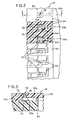
- Fig. 2 is a view of a portion of a heater chip coupled to a nozzle plate with sections of the nozzle plate removed at two different levels;
- Fig. 3 is a view taken along section line 3-3 in Fig. 2;
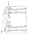
- Fig. 4 is a schematic illustration of a portion of a nozzle plate with first and second nozzles of segment IA and third and fourth nozzles of segment IB represented by solid dots;
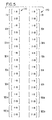
- Fig. 5 is an illustration of a nozzle plate with primary and secondary nozzles of segments IA-VIIIA and segments IB-VIIIB numerically designated;
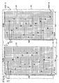
- Fig. 6 is an illustration of a portion of a nozzle plate with first and second nozzles of segment IA and two nozzles of segment IIA represented by numbered circles;
- Fig. 7 is a schematic diagram illustrating a driver circuit;
- Fig. 8 is a timing diagram for high speed mode operation;
- Fig. 9 is a plot showing dots generated by first, second, third and fourth nozzles during consecutive segments of high speed mode firing cycles;
- Fig. 10 is a timing diagram for normal speed mode operation; and
- Fig. 11 is a plot showing dots generated by first, second, third and fourth nozzles during consecutive segments of normal speed mode firing cycles.
- Referring now to Fig. 1, there is shown an ink
jet printing apparatus 10 having first andsecond print cartridges cartridges carrier 40 which, in turn, is slidably supported on aguide rail 42. A printcartridge drive mechanism 44 is provided for effecting reciprocating movement of thecarrier 40 back and forth along theguide rail 42. Thedrive mechanism 44 includes amotor 44a with adrive pulley 44b and adrive belt 44c which extends about thedrive pulley 44b and anidler pulley 44d. Thecarrier 40 is fixedly connected to thedrive belt 44c so as to move with thedrive belt 44c. Operation of themotor 44a effects back and forth movement of thedrive belt 44c and, hence, back and forth movement of thecarrier 40 and theprint cartridges print cartridges paper substrate 12 provided below them. Driven rollers 14 (only one is illustrated in Fig. 1) mounted on ashaft 16 cooperate with pressure rollers 18 (only one of which is illustrated in Fig. 1) to advance thepaper substrate 12 in a direction generally orthogonal to the direction of print cartridge movement. Theshaft 16 is driven by astepper motor assembly 19. - The
print cartridge 20 comprises apolymeric container 22, see Fig. 1, filled with ink and aprinthead 24, see Figs. 2 and 3. Theprinthead 24 comprises aheater chip 50 having a plurality ofresistive heating elements 52. Theprinthead 24 further includes anozzle plate 54 having a plurality ofopenings 56 extending through it which define a plurality ofnozzles 58 through which ink droplets are ejected. The diameter of eachnozzle 58 is from about 5 microns to about 29 microns. - The
nozzle plate 54 may be formed from a flexible polymeric material substrate which is adhered to theheater chip 22 via an adhesive (not shown). Examples of polymeric materials from which thenozzle plate 54 may be formed and adhesives for securing theplate 54 to theheater chip 50 are set out inEP-A-0761448 . As noted therein, theplate 54 may be formed from a polymeric material such as polyimide, polyester, fluorocarbon polymer, or polycarbonate. Theplate 54 is preferably about 15 to about 200 microns thick, and most preferably about 50 to about 125 microns thick. Examples of commercially available plate materials include a polyimide material available from E.I. DuPont de Nemours & Co. under the trademark "KAPTON" and a polyimide material available from Ube (of Japan) under the trademark "UPILEX." - The
plate 54 may be bonded to thechip 50 via any art recognized technique, including a thermocompression bonding process. When theplate 54 and theheater chip 50 are joined together,sections 54a of theplate 54 andportions 50a of theheater chip 50 define a plurality ofbubble chambers 55. Ink supplied by thecontainer 22 flows into thebubble chambers 55 throughink supply channels 55a. Theresistive heating elements 52 are positioned on theheater chip 50 such that eachbubble chamber 55 has only oneheating element 52. Eachbubble chamber 55 communicates with onenozzle 58, see Fig. 3. - The
resistive heating elements 52 are individually addressed by voltage pulses provided by adriver circuit 300, see Fig. 7. Each voltage pulse is applied to one of theheating elements 52 to momentarily vaporize the ink in contact with thatheating element 52 to form a bubble within thebubble chamber 55 in which theheating element 52 is found. The function of the bubble is to displace ink within thebubble chamber 55 such that a droplet of ink is expelled from anozzle 58 associated with thebubble chamber 55. - A flexible circuit (not shown) secured to the
polymeric container 22 is used to provide a path for energy pulses to travel from thedriver circuit 300 to theheater chip 50. Bond pads (not shown) on theheater chip 50 are bonded to end sections of traces (not shown) on the flexible circuit. Current flows from thecircuit 300 to the traces on the flexible circuit and from the traces to the bond pads on theheater chip 50. The current then flows from the bond pads alongconductors 53 to theheating elements 52. - The
print cartridge 30 comprises apolymeric container 32, see Fig. 1, filled with ink and a printhead (not shown). The printhead of theprint cartridge 30 is constructed in essentially the same manner as theprinthead 24 and, as such, will not be described in further detail herein. - In accordance with the present invention, the
nozzle plate 54 is provided with a plurality ofprimary nozzles 110 andsecondary nozzles 120, see Fig. 4. In the illustrated embodiment, there are eight segments IA-VIIIA ofprimary nozzles 110, each segment having 38 nozzles, as represented in Fig. 5. Thus, the total number ofprimary nozzles 110, in the illustrated embodiment, equals 304 nozzles. Similarly, there are eight segments IB-VIIIB ofsecondary nozzles 120, each segment having 38 nozzles. The total number ofsecondary nozzles 120 equals 304 nozzles. Eachsecondary nozzle 120 shares a horizontal axis with aprimary nozzle 110. The specific number of primary andsecondary nozzles nozzle plate 54 are mentioned herein for illustrative purposes only. Hence, the number of primary andsecondary nozzles - The
primary nozzles 110 include first andsecond nozzles nozzle plate columns secondary nozzles 120 include third andfourth nozzles nozzle plate columns second columns fourth columns third columns - The first and
second nozzles fourth nozzles second nozzles first nozzles 112 are represented by odd-numbered circles and thesecond nozzles 114 are represented by even-numbered circles. The 38 nozzles of each of segments IA and IB are numbered 1-19 and 2-20 in Figs. 4-6. - The vertical distance between center points of adjacent first and
second nozzles columns nozzles rows fourth nozzles fourth columns nozzles first nozzles 112, e.g.,nozzles second nozzles 114,third nozzles 122 andfourth nozzles 124 is approximately 1/300 inch. - The numbers adjacent to the dots in Fig. 4 and within the circles in Fig. 6 designate vertical subcolumns within the
nozzle plate columns nozzles nozzle plate columns first nozzles 112, e.g.,nozzles second nozzles 114, e.g.,nozzles - In the illustrated embodiment, the 38 nozzles of each of segments IA-VIIIA and segments IB-VIIIB are arranged in the same order and are spaced from one another in the same manner as are the 38 nozzles of segment IA. Thus, the
secondary nozzles 120 are arranged in the same order and spaced from one another in the same manner as theprimary nozzles 110. Accordingly, the order and spacing of thesecondary nozzles 120 will not be further described herein. - The
driver circuit 300 comprises amicroprocessor 310, an application specific integrated circuit (ASIC) 320, a primary nozzle/secondary nozzleselect circuit 330,decoder circuitry 340 and acommon drive circuit 350. - The primary nozzle/secondary nozzle
select circuit 330 selectively enables either the primary nozzle segments IA-VIIIA or the secondary nozzle segments IB-VIIIB. It has afirst output 330a which is electrically coupled to theprimary nozzles 110 viaconductor 330b. It also has asecond output 330c which is electrically coupled to thesecondary nozzles 120 via aconductor 330d. Thus, a first select signal present at thefirst output 330a is used to select the operation of theprimary nozzles 110 while a second select signal present at thesecond output 330c is used to select the operation of thesecondary nozzles 120. The primary nozzle/secondary nozzleselect circuit 330 is electrically coupled to theASIC 320 and generates appropriate select signals in response to command signals received from theASIC 320. - As noted above, there is a single
resistive heating element 52 associated with each of the primary andsecondary nozzles resistive heating elements 52 are numbered and grouped so as to correspond with the nozzle numbering and segment groupings used in Figs. 4-6. - The
common drive circuit 350 comprises a plurality ofdrivers 352 which are electrically coupled to a power supply 400, theASIC 320 and theresistive heating elements 52. In the illustrated embodiment, sixteendrivers 352 are provided. Each of the sixteendrivers 352 is electrically coupled to one-half of theheating elements 52 associated with one of the primary nozzle segments IA-VIIIA and one-half of theheating elements 52 associated with one of the secondary nozzle segments IB-VIIIB. In Fig. 7, thefirst driver 352, i.e., the driver designatednumber 1, is coupled to theheating elements 52 associated with the upper one-half of thenozzles 110 of the primary nozzle segment IA, i.e., the nozzles numbered 1-19 in Figs. 4-6, and theheating elements 52 associated with the upper one-half of thenozzles 120 of the secondary nozzle segment IB. Thesecond driver 352, i.e., the driver designatednumber 2, is coupled to theheating elements 52 associated with the lower one-half of thenozzles 110 of the primary nozzle segment IA, i.e., the nozzles numbered 2-20 in Figs. 4-6, and theheating elements 52 associated with the lower one-half of thenozzles 120 of the secondary nozzle segment IB. Thefifteenth driver 352, i.e., the driver designatednumber 15, is coupled to theheating elements 52 associated with the upper one-half of thenozzles 110 of the primary nozzle segment VIIIA, and theheating elements 52 associated with the upper one-half of thenozzles 120 of the secondary nozzle segment VIIIB. Thesixteenth driver 352, i.e., the driver numbered 16, is coupled to theheating elements 52 associated with the lower one-half of thenozzles 110 of the primary nozzle segment VIIIA, and theheating elements 52 associated with the lower one-half of thenozzles 120 of the secondary nozzle segment VIIIB. - There are five
input lines 342 extending from theASIC 320 to thedecoder circuitry 340. Twentyaddress lines 344 extend from thedecoder circuitry 340 to theresistive heating elements 52. Eachaddress line 344 extends toheating elements 52 associated with like numbered nozzles in each of the primary and secondary segments IA-VIIIA and IB-VIIIB. For example, thefirst address line 344, i.e., the address line numbered 1 in Fig. 7, is connected to theresistive heating elements 52 associated with thenumber 1 primary andsecondary nozzles tenth address line 344, i.e., the address line numbered 10 in Fig. 7, is connected to theresistive heating elements 52 associated with thenumber 10 primary and secondary nozzles in each of the primary and secondary segments IA-VIIIA and IB-VIIIB. Thetwentieth address line 344, i.e., the address line numbered 20 in Fig. 7, is connected to theresistive heating elements 52 associated with thenumber 20 primary and secondary nozzles in each of the primary and secondary segments IA-VIIIA and IB-VIIIB. As will be discussed more explicitly below, theASIC 320 sends appropriate signals to thedecoder circuitry 340 such that during a given firing cycle, thedecoder circuitry 340 generates appropriate address signals to theheating elements 52 associated with the primary andsecondary nozzles - Each
driver 352 is only activated by theASIC 320 when one of theheating elements 52 to which it is connected is to be fired. Thespecific heating elements 52 fired during a given firing cycle depends upon print data received by themicroprocessor 310 from a separate processor (not shown) electrically coupled to it. Themicroprocessor 310 generates signals which are passed to theASIC 320 and, in turn, theASIC 320 generates appropriate firing signals which are passed to the sixteendrivers 352. The activateddrivers 352 then apply firing voltage pulses to theheating elements 52 in conjunction with the ground path provided by thedecoder circuitry 340. - If the heating element associated with the
number 1primary nozzle 110 in segment IA is to be fired during a given firing cycle segment, thefirst driver 352 will be activated simultaneously with the activation of thefirst output 330a of theselect circuit 330 and thefirst address line 344. If thenumber 2primary nozzle 110 in segment IA is not to be fired during a given firing cycle segment, thesecond driver 352 will not be fired when thefirst output 330a of theselect circuit 330 and thesecond address line 344 are simultaneously activated. If the upper-mostprimary nozzle 110 numbered 10 in segment IA is to be fired, thefirst driver 352 will be fired when thefirst output 330a of theselect circuit 330 and thetenth address line 344 are simultaneously activated. If the lower-mostprimary nozzle 110 numbered 10 in segment IA is not to be fired during a given firing cycle segment, thesecond driver 352 will not be fired when thefirst output 330a of theselect circuit 330 and thetenth address line 344 are simultaneously activated. - The
printing apparatus 10 is selectively operable in one of a normal mode of operation and a high speed mode of operation. The user of theapparatus 10 may select the desired mode via software during printer set up. - A timing diagram for the high speed mode of operation is illustrated in Fig. 8, wherein an expanded high speed
mode firing cycle 500 is shown. Thedriver circuit 300 is capable of applying, depending upon print data received by themicroprocessor 310 from the separate processor (not shown) electrically coupled to it, first firing pulses tofirst heating elements 52, i.e., theheating elements 52 associated with the first nozzles 112 (the odd-numbered primary nozzles), during afirst segment 502a of each high speed mode firing cycle, second firing pulses tosecond heating elements 52, i.e., theheating elements 52 associated with the second nozzles 114 (the even-numbered primary nozzles), during a second segment 502b of each high speed mode firing cycle, third firing pulses tothird heating elements 52, i.e., theheating elements 52 associated with the third nozzles 122 (the odd-numbered secondary nozzles), during athird segment 502c of each high speed mode firing cycle, and fourth firing pulses tofourth heating elements 52, i.e., theheating elements 52 associated with the fourth nozzles 124 (the even-numbered secondary nozzles), during afourth segment 502d of each high speed mode firing cycle. - As illustrated in Fig. 8, during the first and
third segments ASIC 320 causes thedecoder circuitry 340 to cycle through its odd address lines 344. During the second andfourth segments 502b and 502d of each high speed mode firing cycle, theASIC 320 causes thedecoder circuitry 340 to cycle through its even address lines 344. Thefirst output 330a is active only during the first andsecond segments 502a and 502b. Thesecond output 330c is active only during the third andfourth segments - During the
first segment 502a of the high speed mode firing cycle, thefirst output 330a is active and, depending upon the print data received by themicroprocessor 310, theappropriate drivers 352 are activated as thedecoder circuitry 340 cycles through itsodd address lines 344 such that the desired first heating elements associated with thefirst nozzles 112 in segments IA-VIIIA are fired. During the second segment 502b of the high speed mode firing cycle, thefirst output 330a is active and, depending upon the print data received by themicroprocessor 310, theappropriate drivers 352 are activated as thedecoder circuitry 340 cycles through itseven address lines 344 such that the desiredsecond heating elements 52 associated with thesecond nozzles 114 in segments IA-VIIIA are fired. During thethird segment 502c of the high speed mode firing cycle, thesecond output 330c is active and, depending upon the print data received by themicroprocessor 310, theappropriate drivers 352 are activated as thedecoder circuitry 340 cycles through itsodd address lines 344 such that the desiredthird heating elements 52 associated with thethird nozzles 122 in segments IB-VIIIB are fired. During thefourth segment 502d of the high speed mode firing cycle, thesecond output 330c is active and, depending upon the print data received by themicroprocessor 310, theappropriate drivers 352 are activated as thedecoder circuitry 340 cycles through itseven address lines 344 such that the desiredfourth heating elements 52 associated with thefourth nozzles 124 in segments IB-VIIIB are fired. - The length of time of each of the first, second, third and
fourth segments 502a-502d of the high speed mode firing cycle is from about 12 µseconds to about 64 µseconds. The printhead speed is from about 13 inches/second (330mm/s) to about 70 inches/second (1.78m/s). In the illustrated embodiment, the length of time of each of thesegments 502a-502d is about 20.825 µseconds such that the total firing cycle time is approximately 83.3 µseconds. Further, the printhead speed is about 40 inches/second (1.02m/s) such that the printhead travels approximately 1/300 inch per firing cycle. - It is noted that at the beginning of each of the second and
fourth segments 502b and 502d of the high speed mode firing cycle, a delay of about .868 µseconds occurs before theheating element 52 associated with thenumber 2second nozzle 114 and thenumber 2fourth nozzle 124 are fired. This delay period is equal to the amount of time it takes the printhead to move 1/28,800 inch, the length of one subcolumn within each of the second andfourth columns - In Fig. 9, a plot is illustrated showing dots generated by a
first nozzle 112, asecond nozzle 114, athird nozzle 122 and afourth nozzle 124 during high speed mode operation. The initial positions of thenozzles third nozzles nozzles dots 1A are formed by thefirst nozzle 112,dots 2A are formed by thesecond nozzle 114, dots 1 B are formed by thethird nozzle 122 anddots 2B are formed by thefourth nozzle 124. As can be seen from Fig. 9, during afirst segment 502a of a first high speed mode firing cycle,nozzle 112 is fired and the printhead moves a distance across the paper substrate 12 (from right to left) equal to 1/1200 inch (1/47mm). During a second segment 502b of the first high speed mode firing cycle,nozzle 114 is fired and the printhead moves another 1/1200 inch across thepaper substrate 12. Thedot 2A created by thenozzle 114 is horizontally spaced approximately 4/1200 inch from thedot 1A created by thenozzle 112. During athird segment 502c of the first high speed firing cycle,nozzle 122 is fired and the printhead moves another 1/1200 inch across thepaper substrate 12. During afourth segment 502d of the first high speed firing cycle,nozzle 124 is fired and the printhead moves another 1/1200 inch across thepaper substrate 12. Thedot 2B created bynozzle 124 is horizontally spaced approximately 4/1200 inch from the dot 1B created by thenozzle 122. As is apparent from Fig. 9, the dots are horizontally spaced from one another by a distance of 1/600 inch. Thus, 600 dots per inch horizontal resolution occurs during high speed mode printing. This results because the first andsecond columns - A timing diagram for the normal speed mode of operation is illustrated in Fig. 10, wherein an expanded normal speed
mode firing cycle 600 is shown. Thedriver circuit 300 is capable of alternatively applying, depending upon print data received by themicroprocessor 310 from the separate processor (not shown) electrically coupled to it, first and second firing pulses to first andsecond heating elements 52, i.e., theheating elements 52 associated with the first andsecond nozzles first segment 602a of each normal speed mode firing cycle; third and fourth firing pulses to third andfourth heating elements 52, i.e., theheating elements 52 associated with the third andfourth nozzles second segment 602b of each normal speed mode firing cycle; first and second firing pulses to the first andsecond heating elements 52 during athird segment 602c of each normal speed mode firing cycle and third and fourth firing pulses to the third andfourth heating elements 52 during afourth segment 602d of each normal speed mode firing cycle. - During each of the
segments 602a-602d of the normal speed mode firing cycle, theASIC 320 causes thedecoder circuitry 340 to cycle through each of its twentyaddress lines 344. Thefirst output 330a is active during the first andthird segments second output 330c is active during the second andfourth segments - The length of time of each of the first, second, third and
fourth segments 602a-602d of the normal speed mode firing cycle is from about 24 µseconds to about 64 seconds. The printhead speed is from about 13 inches/second (330mm/s) to about 35 inches/second (890mm/s). In the illustrated embodiment, the length of time of each of thesegments 602a-602d is about 41.675 µseconds such that the total firing cycle time is approximately 166.7 µseconds. Further, the printhead speed is about 20 inches/second (508mm/s) such that the printhead travels approximately 1/300 inch per firing cycle. - In Fig. 11, a plot is illustrated showing dots generated by a
first nozzle 112, asecond nozzle 114, athird nozzle 122 and afourth nozzle 124 during normal speed mode operation. The initial positions of thenozzles nozzles dots 1A are formed by thefirst nozzle 112,dots 2A are formed by thesecond nozzle 114, dots 1B are formed by thethird nozzle 122 anddots 2B are formed by thefourth nozzle 124. As can be seen from Fig. 11, during afirst segment 602a of a normal speed mode firing cycle,nozzles paper substrate 12 equal to 1/1200 inch. During asecond segment 602b of the normal speed mode firing cycle,nozzles paper substrate 12. During athird segment 602c of the normal speed firing cycle,nozzles paper substrate 12. During afourth segment 602d of the normal speed firing cycle,nozzles paper substrate 12. As apparent from Fig. 11, the dots created by thenozzles stepper motor assembly 19 by themicroprocessor 310. - It is further contemplated that instead of having a
single nozzle plate 54 coupled to asingle heater chip 50 including both the primary andsecondary nozzles
Claims (13)
- An ink jet printing apparatus (10) for forming a printed image by printing a rectilinear array of horizontal rows and vertical columns of dots on a print medium as an inkjet printhead moves across the print medium in a line scan direction, said apparatus comprising:a print cartridge (20, 30) including the inkjet printhead, which comprises a heater chip and a nozzle plate coupled to said heater chip, said heater chip having first, second, third and fourth heating elements (52), and said nozzle plate having a plurality of primary and secondary nozzles, said primary nozzles including first and second nozzles positioned in first and second nozzle plate columns and said secondary nozzles including third and fourth nozzles positioned in third and fourth nozzle plate columns, said primary nozzles arranged and spaced from one another in the same manner as said secondary nozzles, each of said nozzles having one of said heating elements associated therewith for generating energy to discharge ink therefrom, whereineach one of said third nozzles is arranged to position a droplet in the same row of dots during a given line scan of the printhead as a corresponding first nozzle; andeach one of said fourth nozzles is arranged to position a droplet in the same row of dots during a given line scan of the printhead as a corresponding second nozzle; said inkjet printing apparatus characterized by further comprising:a driver circuit (300) electrically coupled to said print cartridge, and configured to apply firing pulses to said heating elements associated with both a primary nozzle and a secondary nozzle during a given line scan.
- An ink jet printing apparatus as set forth in claim 1, wherein said first and second columns are spaced apart from one another by a distance equal to X/1200 inch (X/47 mm), wherein X is an odd integer ≥ 3 and ≤ 9.
- An ink jet printing apparatus as set forth in claim 1 or 2, wherein said third and fourth columns are spaced apart from one another by a distance equal to X/1200 inch (X/47 mm), wherein X is an odd integer ≥ 3 and ≤ 9.
- An ink jet printing apparatus as set forth in claims 1, 2 or 3, wherein said first and third columns are spaced apart from one another by a distance equal to Y/600 inch (Y/24 mm), wherein Y is an even integer ≥ 40.
- An ink jet printing apparatus as set forth in claims 1, 2, 3 or 4, wherein said second nozzles are staggered relative to said first nozzles and said fourth nozzles are staggered relative to said third nozzles.
- An ink jet printing apparatus as set forth in claim 5, wherein the vertical distance between adjacent first and second nozzles is approximately 1/600 inch (1/24 mm).
- An ink jet printing apparatus printhead as set forth in claim 5 or 6, wherein the vertical distance between adjacent first nozzles is approximately 1/300 inch (0.085 mm).
- An ink jet printing apparatus as set forth in any of claims 1 to 7, wherein said driver circuit is selectively operable in one of a normal mode of operation and a high speed mode of operation.
- An ink jet printing apparatus as set forth in any of claims 1 to 7, wherein said first nozzles are associated with said first heating elements, said second nozzles are associated with said second heating elements, said third nozzles are associated with said third heating elements and said fourth nozzles are associated with said fourth heating element.
- An ink jet printing apparatus as set forth in claim 9, wherein said driver circuit alternatively applies firing pulses to said first and second heating elements during a first segment of a normal mode firing cycle and alternatively applies firing pulses to said third and fourth heating elements during a second segment of said normal mode firing cycle.
- An ink jet printing apparatus as set forth in claim 10, wherein the length of time of each of said first and second segments of said normal mode firing cycle is from about 24 µseconds to about 64 µseconds.
- An ink jet printing apparatus as set forth in claim 9,10 or 11, wherein said driver circuit applies first firing pulses to said first elements during a first segment of high speed mode firing cycle, second firing pulses to said second heating elements during a second segment of said high speed mode firing cycle, third firing pulses to said third heating elements during a third segment of said high speed mode firing cycle, and fourth firing pulses to said fourth heating elements during a fourth segment of said high speed mode firing cycle.
- An ink jet printing apparatus as set forth in claim 12, wherein the length of time of each of said first, second, third and fourth segments of said high speed mode firing cycle is from about 12 µseconds to about 64 µseconds.
Priority Applications (1)
| Application Number | Priority Date | Filing Date | Title |
|---|---|---|---|
| EP07013731A EP1864812A1 (en) | 1997-11-04 | 1998-11-04 | Ink jet printing apparatus |
Applications Claiming Priority (2)
| Application Number | Priority Date | Filing Date | Title |
|---|---|---|---|
| US08/964,282 US6017112A (en) | 1997-11-04 | 1997-11-04 | Ink jet printing apparatus having a print cartridge with primary and secondary nozzles |
| US964282 | 1997-11-04 |
Related Child Applications (1)
| Application Number | Title | Priority Date | Filing Date |
|---|---|---|---|
| EP07013731A Division EP1864812A1 (en) | 1997-11-04 | 1998-11-04 | Ink jet printing apparatus |
Publications (3)
| Publication Number | Publication Date |
|---|---|
| EP0914948A2 EP0914948A2 (en) | 1999-05-12 |
| EP0914948A3 EP0914948A3 (en) | 1999-12-15 |
| EP0914948B1 true EP0914948B1 (en) | 2007-07-18 |
Family
ID=25508353
Family Applications (2)
| Application Number | Title | Priority Date | Filing Date |
|---|---|---|---|
| EP98309007A Expired - Lifetime EP0914948B1 (en) | 1997-11-04 | 1998-11-04 | Ink jet printing apparatus |
| EP07013731A Withdrawn EP1864812A1 (en) | 1997-11-04 | 1998-11-04 | Ink jet printing apparatus |
Family Applications After (1)
| Application Number | Title | Priority Date | Filing Date |
|---|---|---|---|
| EP07013731A Withdrawn EP1864812A1 (en) | 1997-11-04 | 1998-11-04 | Ink jet printing apparatus |
Country Status (4)
| Country | Link |
|---|---|
| US (1) | US6017112A (en) |
| EP (2) | EP0914948B1 (en) |
| JP (1) | JP4825339B2 (en) |
| DE (1) | DE69838089T2 (en) |
Families Citing this family (51)
| Publication number | Priority date | Publication date | Assignee | Title |
|---|---|---|---|---|
| US6416162B1 (en) * | 1998-12-24 | 2002-07-09 | Seiko Epson Corporation | Color printing using a vertical nozzle array head |
| KR20010028853A (en) * | 1999-09-27 | 2001-04-06 | 윤종용 | Ink jet printer head |
| US6527365B1 (en) | 2000-10-20 | 2003-03-04 | Silverbrook Research Pty Ltd. | Printhead for pen |
| AU772145B2 (en) * | 1999-10-25 | 2004-04-08 | Silverbrook Research Pty Ltd | Electronically controllable pen |
| AU2432201A (en) * | 2000-01-04 | 2001-07-16 | Encad, Inc. | Print masks for high speed ink jet printing |
| US6502920B1 (en) * | 2000-02-04 | 2003-01-07 | Lexmark International, Inc | Ink jet print head having offset nozzle arrays |
| US6530645B2 (en) | 2000-04-03 | 2003-03-11 | Eastman Kodak Company | Print masks for high speed ink jet printing |
| US6575560B2 (en) * | 2000-07-10 | 2003-06-10 | Canon Kabushiki Kaisha | Liquid discharge recording head and liquid discharge recording apparatus |
| US6902252B1 (en) * | 2000-08-16 | 2005-06-07 | Hewlett-Packard Development Company, L.P. | Fluid ejection device with staggered ink drop generators |
| US6585352B1 (en) * | 2000-08-16 | 2003-07-01 | Hewlett-Packard Development Company, L.P. | Compact high-performance, high-density ink jet printhead |
| AU778400B2 (en) * | 2000-10-20 | 2004-12-02 | Silverbrook Research Pty Ltd | Printhead for pen |
| SG152904A1 (en) | 2000-10-20 | 2009-06-29 | Silverbrook Res Pty Ltd | Cartridge for an electronic pen |
| WO2002034533A1 (en) * | 2000-10-20 | 2002-05-02 | Silverbrook Research Pty Ltd | Capping mechanism for pen printhead |
| US7456994B2 (en) | 2000-10-20 | 2008-11-25 | Silverbrook Research Pty Ltd | Mobile telecommunications device with stylus having printhead tip |
| US7431449B2 (en) | 2000-10-20 | 2008-10-07 | Silverbrook Research Pty Ltd | Mobile telecommunications device with interactive paper sensor |
| US6582042B1 (en) * | 2000-10-30 | 2003-06-24 | Hewlett-Packard Development Company, L.P. | Method and apparatus for transferring information to a printhead |
| US6523935B2 (en) | 2001-01-30 | 2003-02-25 | Hewlett-Packard Company | Narrow ink jet printhead |
| US6655770B2 (en) * | 2001-05-02 | 2003-12-02 | Hewlett-Packard Development Company, L.P. | Apparatus and method for printing with showerhead groups |
| US6422676B1 (en) * | 2001-06-19 | 2002-07-23 | Hewlett-Packard Company | Compact ink jet printhead |
| US7086718B2 (en) | 2002-11-23 | 2006-08-08 | Silverbrook Research Pty Ltd | Thermal ink jet printhead with high nozzle areal density |
| JP4161881B2 (en) * | 2003-11-13 | 2008-10-08 | ソニー株式会社 | Liquid ejection method |
| US7703870B2 (en) * | 2003-12-25 | 2010-04-27 | National Institute Of Advanced Industrial Science And Technology | Liquid ejection apparatus |
| KR100678419B1 (en) * | 2005-04-01 | 2007-02-02 | 삼성전기주식회사 | Method for surface treatment of board, method for forming wiring and wiring substrate |
| US20070076082A1 (en) * | 2005-09-30 | 2007-04-05 | Lexmark International, Inc. | Methods and apparatuses for measuring print area using hand-held printer |
| US7500732B2 (en) * | 2005-09-30 | 2009-03-10 | Lexmark International, Inc. | Maintenance and docking station for a hand-held printer |
| US7735951B2 (en) * | 2005-11-15 | 2010-06-15 | Lexmark International, Inc. | Alignment method for hand-operated printer |
| US20070120937A1 (en) * | 2005-11-30 | 2007-05-31 | Lexmark International, Inc. | System and method for hand-held printing |
| US7524051B2 (en) * | 2005-12-20 | 2009-04-28 | Lexmark International, Inc. | Hand-operated printer having a user interface |
| US7399129B2 (en) * | 2005-12-20 | 2008-07-15 | Lexmark International, Inc. | User interface for a hand-operated printer |
| WO2007099774A1 (en) * | 2006-02-28 | 2007-09-07 | Konica Minolta Holdings, Inc. | Liquid delivery head, liquid delivery apparatus, and liquid delivery method |
| US20070237561A1 (en) * | 2006-04-11 | 2007-10-11 | Lexmark International Inc. | Methods and apparatuses for sensing a print area using a hand-held printer |
| US7748839B2 (en) * | 2006-05-09 | 2010-07-06 | Lexmark International, Inc. | Handheld printing with reference indicia |
| US7682017B2 (en) * | 2006-05-10 | 2010-03-23 | Lexmark International, Inc. | Handheld printer minimizing printing defects |
| US7787145B2 (en) * | 2006-06-29 | 2010-08-31 | Lexmark International, Inc. | Methods for improving print quality in a hand-held printer |
| US20080030534A1 (en) * | 2006-08-02 | 2008-02-07 | Adam Jude Ahne | Hand Held Micro-fluid Ejection Devices Configured to Eject Fluid without Referential Position Information and Method of Ejecting Fluid |
| US20080079956A1 (en) * | 2006-09-21 | 2008-04-03 | Mahesan Chelvayohan | Hand-Held Printer Having An Integrated Digital Camera Scanner |
| US20080075513A1 (en) * | 2006-09-26 | 2008-03-27 | Douglas Laurence Robertson | Methods for a Maintenance Algorithm in Hand Held Printers |
| US7748840B2 (en) * | 2006-09-27 | 2010-07-06 | Lexmark International, Inc. | Methods and apparatus for handheld printing with optical positioning |
| US7918519B2 (en) | 2006-09-27 | 2011-04-05 | Lexmark International, Inc. | Methods and apparatus for handheld printing with optical positioning |
| US7938531B2 (en) | 2006-09-27 | 2011-05-10 | Lexmark International, Inc. | Methods and apparatus for handheld printing with optical positioning |
| DE102007046910A1 (en) * | 2006-09-29 | 2008-04-03 | Daimler Ag | Deformable substrate with microstructured surface, comprises applied material, where applied material is configured as individual pixels, which is printed onto substrate |
| JP4479732B2 (en) * | 2007-01-30 | 2010-06-09 | ブラザー工業株式会社 | Inkjet recording device |
| US7938532B2 (en) | 2007-02-16 | 2011-05-10 | Lexmark International, Inc. | Hand held printer with vertical misalignment correction |
| US20080219737A1 (en) * | 2007-03-07 | 2008-09-11 | Michael David Stilz | Hand Held Printer Having A Doppler Position Sensor |
| CN101274516B (en) * | 2007-03-29 | 2013-04-24 | 研能科技股份有限公司 | Polychromatic ink gun structure suitable for ink cartridge |
| CN101274515B (en) * | 2007-03-29 | 2013-04-24 | 研能科技股份有限公司 | Monochrome ink gun structure |
| CN103171287A (en) * | 2007-03-29 | 2013-06-26 | 研能科技股份有限公司 | Single-color ink jet head structure |
| US7758155B2 (en) * | 2007-05-15 | 2010-07-20 | Eastman Kodak Company | Monolithic printhead with multiple rows of inkjet orifices |
| US8092006B2 (en) | 2007-06-22 | 2012-01-10 | Lexmark International, Inc. | Handheld printer configuration |
| US20090040286A1 (en) * | 2007-08-08 | 2009-02-12 | Tan Theresa Joy L | Print scheduling in handheld printers |
| JP4557021B2 (en) * | 2008-02-29 | 2010-10-06 | ブラザー工業株式会社 | Droplet ejector |
Citations (1)
| Publication number | Priority date | Publication date | Assignee | Title |
|---|---|---|---|---|
| WO1996032285A1 (en) * | 1995-04-12 | 1996-10-17 | Eastman Kodak Company | A self-aligned construction and manufacturing process for monolithic print heads |
Family Cites Families (48)
| Publication number | Priority date | Publication date | Assignee | Title |
|---|---|---|---|---|
| US4097873A (en) * | 1977-02-28 | 1978-06-27 | International Business Machines Corporation | Ink jet printer for selectively printing different resolutions |
| US4463359A (en) * | 1979-04-02 | 1984-07-31 | Canon Kabushiki Kaisha | Droplet generating method and apparatus thereof |
| US4593295A (en) * | 1982-06-08 | 1986-06-03 | Canon Kabushiki Kaisha | Ink jet image recording device with pitch-shifted recording elements |
| JPH0755560B2 (en) * | 1985-05-09 | 1995-06-14 | シャープ株式会社 | Inkjet printer |
| EP0224937B1 (en) * | 1985-12-06 | 1991-11-21 | Hewlett-Packard Company | Thermal ink jet print head assembly |
| JPS63254050A (en) * | 1987-04-13 | 1988-10-20 | Canon Inc | Recording method of dot printer |
| US4812859A (en) * | 1987-09-17 | 1989-03-14 | Hewlett-Packard Company | Multi-chamber ink jet recording head for color use |
| JP2731003B2 (en) * | 1988-12-06 | 1998-03-25 | キヤノン株式会社 | Liquid jet recording device |
| JPH0365357A (en) * | 1989-08-02 | 1991-03-20 | Nec Corp | Thermal recording device |
| US5124720A (en) * | 1990-08-01 | 1992-06-23 | Hewlett-Packard Company | Fault-tolerant dot-matrix printing |
| JP2839966B2 (en) * | 1990-08-17 | 1998-12-24 | キヤノン株式会社 | Recovery method for inkjet recording apparatus and inkjet recording apparatus |
| WO1992006792A1 (en) * | 1990-10-12 | 1992-04-30 | Yoshino Kogyosho Co., Ltd. | Foaming nozzle to be mounted on atomizer |
| AU657720B2 (en) * | 1991-01-30 | 1995-03-23 | Canon Kabushiki Kaisha | A bubblejet image reproducing apparatus |
| JPH04338563A (en) * | 1991-05-15 | 1992-11-25 | Minolta Camera Co Ltd | Image recording device |
| JP2986124B2 (en) * | 1991-06-14 | 1999-12-06 | キヤノン株式会社 | Ink jet recording device |
| CA2074906C (en) * | 1991-08-01 | 2000-09-12 | Hiromitsu Hirabayashi | Ink jet recording apparatus having temperature control function |
| US5208605A (en) * | 1991-10-03 | 1993-05-04 | Xerox Corporation | Multi-resolution roofshooter printheads |
| US5241325A (en) * | 1991-10-31 | 1993-08-31 | Hewlett-Packard Company | Print cartridge cam actuator linkage |
| JPH06171084A (en) * | 1992-02-07 | 1994-06-21 | Seiko Epson Corp | Ink jet recording head |
| JPH05229162A (en) * | 1992-02-24 | 1993-09-07 | Rohm Co Ltd | Thermal head and electronic appliance provided with that |
| US5648806A (en) * | 1992-04-02 | 1997-07-15 | Hewlett-Packard Company | Stable substrate structure for a wide swath nozzle array in a high resolution inkjet printer |
| US5349375A (en) * | 1992-04-16 | 1994-09-20 | Lexmark International, Inc. | Ink jet printer dot placement compensation method |
| DE69307590T2 (en) * | 1992-05-11 | 1997-05-15 | Hewlett Packard Co | Method and device for printing density control in an inkjet printer |
| JPH0671875A (en) * | 1992-06-30 | 1994-03-15 | Fuji Xerox Co Ltd | Ink-jet recorder |
| US5469198A (en) * | 1992-08-03 | 1995-11-21 | Hewlett-Packard Company | Multiple pass printing for achieving increased print resolution |
| US5559930A (en) * | 1992-08-03 | 1996-09-24 | Hewlett-Packard Company | Method for reducing pixel density along a plurality of axes of a multiple dimension image representation |
| US5412410A (en) * | 1993-01-04 | 1995-05-02 | Xerox Corporation | Ink jet printhead for continuous tone and text printing |
| JP3569543B2 (en) * | 1993-03-31 | 2004-09-22 | ヒューレット・パッカード・カンパニー | Integrated printhead addressing system. |
| US6109720A (en) * | 1993-04-28 | 2000-08-29 | Canon Kabushiki Kaisha | Method and apparatus for ink-jet recording with inks having different densities |
| US5426457A (en) * | 1993-04-30 | 1995-06-20 | Hewlett-Packard Company | Direction-independent encoder reading; position leading and delay, and uncertainty to improve bidirectional printing |
| US5480240A (en) * | 1993-12-01 | 1996-01-02 | Lexmark International, Inc. | Print quality enhancement method and apparatus |
| US5790150A (en) * | 1994-02-17 | 1998-08-04 | Colorspan Corporation | Method for controlling an ink jet printer in a multipass printing mode |
| US5602574A (en) * | 1994-08-31 | 1997-02-11 | Hewlett-Packard Company | Matrix pen arrangement for inkjet printing |
| US5587730A (en) * | 1994-09-30 | 1996-12-24 | Xerox Corporation | Redundant full width array thermal ink jet printing for improved reliability |
| US5627572A (en) * | 1994-10-24 | 1997-05-06 | Lexmark International, Inc. | Programmable head type detection and maintenance system |
| EP0709212A1 (en) * | 1994-10-31 | 1996-05-01 | Hewlett-Packard Company | Pen-based degassing scheme for ink jet pens |
| US5631746A (en) * | 1994-11-15 | 1997-05-20 | Lexmark International, Inc. | High resolution simulation printing by printing adjoining pels |
| US5581284A (en) * | 1994-11-25 | 1996-12-03 | Xerox Corporation | Method of extending the life of a printbar of a color ink jet printer |
| JPH08174805A (en) * | 1994-12-21 | 1996-07-09 | Rohm Co Ltd | Ink jet printer |
| JPH08258292A (en) * | 1995-03-20 | 1996-10-08 | Canon Inc | Recording apparatus |
| JP3606403B2 (en) * | 1995-04-27 | 2005-01-05 | セイコーエプソン株式会社 | Printing apparatus and printing method |
| US5598192A (en) * | 1995-06-08 | 1997-01-28 | Xerox Corporation | Thermal ink jet printhead with extended print capability |
| JP3987139B2 (en) * | 1995-06-27 | 2007-10-03 | セイコーエプソン株式会社 | Inkjet recording head |
| DE69625002T2 (en) * | 1995-08-28 | 2003-07-31 | Lexmark Int Inc | Method of forming a nozzle structure for an ink jet printhead |
| US5757400A (en) * | 1996-02-01 | 1998-05-26 | Spectra, Inc. | High resolution matrix ink jet arrangement |
| JPH09272205A (en) * | 1996-04-04 | 1997-10-21 | Seiko Epson Corp | Ink jet recording head of lamination type |
| JPH09309201A (en) * | 1996-05-20 | 1997-12-02 | Brother Ind Ltd | Image recording device |
| US5984455A (en) * | 1997-11-04 | 1999-11-16 | Lexmark International, Inc. | Ink jet printing apparatus having primary and secondary nozzles |
-
1997
- 1997-11-04 US US08/964,282 patent/US6017112A/en not_active Expired - Lifetime
-
1998
- 1998-11-04 JP JP35066398A patent/JP4825339B2/en not_active Expired - Fee Related
- 1998-11-04 EP EP98309007A patent/EP0914948B1/en not_active Expired - Lifetime
- 1998-11-04 EP EP07013731A patent/EP1864812A1/en not_active Withdrawn
- 1998-11-04 DE DE69838089T patent/DE69838089T2/en not_active Expired - Lifetime
Patent Citations (1)
| Publication number | Priority date | Publication date | Assignee | Title |
|---|---|---|---|---|
| WO1996032285A1 (en) * | 1995-04-12 | 1996-10-17 | Eastman Kodak Company | A self-aligned construction and manufacturing process for monolithic print heads |
Also Published As
| Publication number | Publication date |
|---|---|
| DE69838089D1 (en) | 2007-08-30 |
| JP4825339B2 (en) | 2011-11-30 |
| EP1864812A1 (en) | 2007-12-12 |
| EP0914948A2 (en) | 1999-05-12 |
| DE69838089T2 (en) | 2008-03-20 |
| JPH11235816A (en) | 1999-08-31 |
| US6017112A (en) | 2000-01-25 |
| EP0914948A3 (en) | 1999-12-15 |
Similar Documents
| Publication | Publication Date | Title |
|---|---|---|
| EP0914948B1 (en) | Ink jet printing apparatus | |
| EP0914949B1 (en) | Ink jet printing apparatus | |
| EP0914954B1 (en) | Ink jet printing apparatus | |
| EP0609997B1 (en) | A system for reducing drive energy in a high speed thermal ink jet printer | |
| US6406115B2 (en) | Method of printing with multiple sized drop ejectors on a single printhead | |
| EP1309453B1 (en) | Ink jet printhead having four staggered rows of nozzles | |
| EP0767061B1 (en) | Liquid ink printer for producing high resolution images | |
| AU2001286546A1 (en) | Ink jet printhead having four staggered rows of nozzles | |
| US6402280B2 (en) | Printhead with close-packed configuration of alternating sized drop ejectors and method of firing such drop ejectors | |
| US6257690B1 (en) | Ink ejection element firing order to minimize horizontal banding and the jaggedness of vertical lines | |
| JPH10138462A (en) | Printer | |
| US5790152A (en) | Thermal ink-jet printhead for creating spots of selectable sizes | |
| EP1022148B1 (en) | Printer having media advance coordinated with primitive size | |
| US6457798B1 (en) | Six gray level roofshooter fluid ejector | |
| EP0225169B1 (en) | Ink jet apparatus | |
| EP0897804A2 (en) | Liquid ink printhead | |
| JPH11320894A (en) | Ink jet head | |
| JPH07276640A (en) | Ink jet recorder | |
| JPH10119274A (en) | Ink jet printer and driving method for ink jet head |
Legal Events
| Date | Code | Title | Description |
|---|---|---|---|
| PUAI | Public reference made under article 153(3) epc to a published international application that has entered the european phase |
Free format text: ORIGINAL CODE: 0009012 |
|
| AK | Designated contracting states |
Kind code of ref document: A2 Designated state(s): DE FR GB IT NL |
|
| AX | Request for extension of the european patent |
Free format text: AL;LT;LV;MK;RO;SI |
|
| PUAL | Search report despatched |
Free format text: ORIGINAL CODE: 0009013 |
|
| AK | Designated contracting states |
Kind code of ref document: A3 Designated state(s): AT BE CH CY DE DK ES FI FR GB GR IE IT LI LU MC NL PT SE |
|
| AX | Request for extension of the european patent |
Free format text: AL;LT;LV;MK;RO;SI |
|
| 17P | Request for examination filed |
Effective date: 20000607 |
|
| AKX | Designation fees paid |
Free format text: DE FR GB IT NL |
|
| 17Q | First examination report despatched |
Effective date: 20040902 |
|
| GRAP | Despatch of communication of intention to grant a patent |
Free format text: ORIGINAL CODE: EPIDOSNIGR1 |
|
| GRAS | Grant fee paid |
Free format text: ORIGINAL CODE: EPIDOSNIGR3 |
|
| GRAA | (expected) grant |
Free format text: ORIGINAL CODE: 0009210 |
|
| AK | Designated contracting states |
Kind code of ref document: B1 Designated state(s): DE FR GB IT NL |
|
| REG | Reference to a national code |
Ref country code: GB Ref legal event code: FG4D |
|
| REF | Corresponds to: |
Ref document number: 69838089 Country of ref document: DE Date of ref document: 20070830 Kind code of ref document: P |
|
| ET | Fr: translation filed | ||
| PLBE | No opposition filed within time limit |
Free format text: ORIGINAL CODE: 0009261 |
|
| STAA | Information on the status of an ep patent application or granted ep patent |
Free format text: STATUS: NO OPPOSITION FILED WITHIN TIME LIMIT |
|
| 26N | No opposition filed |
Effective date: 20080421 |
|
| REG | Reference to a national code |
Ref country code: GB Ref legal event code: 732E Free format text: REGISTERED BETWEEN 20131107 AND 20131113 |
|
| REG | Reference to a national code |
Ref country code: DE Ref legal event code: R082 Ref document number: 69838089 Country of ref document: DE Representative=s name: ABITZ & PARTNER PATENTANWAELTE MBB, DE Effective date: 20131107 Ref country code: DE Ref legal event code: R082 Ref document number: 69838089 Country of ref document: DE Representative=s name: ABITZ & PARTNER, DE Effective date: 20131107 Ref country code: DE Ref legal event code: R081 Ref document number: 69838089 Country of ref document: DE Owner name: FUNAI ELECTRIC CO., LTD, DAITO CITY, JP Free format text: FORMER OWNER: LEXMARK INTERNATIONAL, INC., LEXINGTON, KY., US Effective date: 20131107 Ref country code: DE Ref legal event code: R081 Ref document number: 69838089 Country of ref document: DE Owner name: FUNAI ELECTRIC CO., LTD, JP Free format text: FORMER OWNER: LEXMARK INTERNATIONAL, INC., LEXINGTON, US Effective date: 20131107 |
|
| REG | Reference to a national code |
Ref country code: NL Ref legal event code: SD Effective date: 20140120 |
|
| REG | Reference to a national code |
Ref country code: FR Ref legal event code: TP Owner name: FUNAI ELECTRIC CO LTD, JP Effective date: 20140102 |
|
| REG | Reference to a national code |
Ref country code: NL Ref legal event code: SD Effective date: 20140120 |
|
| REG | Reference to a national code |
Ref country code: FR Ref legal event code: PLFP Year of fee payment: 18 |
|
| PGFP | Annual fee paid to national office [announced via postgrant information from national office to epo] |
Ref country code: GB Payment date: 20151104 Year of fee payment: 18 Ref country code: IT Payment date: 20151124 Year of fee payment: 18 |
|
| PGFP | Annual fee paid to national office [announced via postgrant information from national office to epo] |
Ref country code: FR Payment date: 20151008 Year of fee payment: 18 Ref country code: NL Payment date: 20151012 Year of fee payment: 18 |
|
| REG | Reference to a national code |
Ref country code: DE Ref legal event code: R084 Ref document number: 69838089 Country of ref document: DE |
|
| REG | Reference to a national code |
Ref country code: NL Ref legal event code: MM Effective date: 20161201 |
|
| GBPC | Gb: european patent ceased through non-payment of renewal fee |
Effective date: 20161104 |
|
| REG | Reference to a national code |
Ref country code: FR Ref legal event code: ST Effective date: 20170731 |
|
| PG25 | Lapsed in a contracting state [announced via postgrant information from national office to epo] |
Ref country code: NL Free format text: LAPSE BECAUSE OF NON-PAYMENT OF DUE FEES Effective date: 20161201 |
|
| PG25 | Lapsed in a contracting state [announced via postgrant information from national office to epo] |
Ref country code: IT Free format text: LAPSE BECAUSE OF NON-PAYMENT OF DUE FEES Effective date: 20161104 Ref country code: FR Free format text: LAPSE BECAUSE OF NON-PAYMENT OF DUE FEES Effective date: 20161130 |
|
| PG25 | Lapsed in a contracting state [announced via postgrant information from national office to epo] |
Ref country code: GB Free format text: LAPSE BECAUSE OF NON-PAYMENT OF DUE FEES Effective date: 20161104 |
|
| PGFP | Annual fee paid to national office [announced via postgrant information from national office to epo] |
Ref country code: DE Payment date: 20171031 Year of fee payment: 20 |
|
| REG | Reference to a national code |
Ref country code: DE Ref legal event code: R071 Ref document number: 69838089 Country of ref document: DE |