EP0913702A1 - Navigation receiver, in particular of GPS type - Google Patents
Navigation receiver, in particular of GPS type Download PDFInfo
- Publication number
- EP0913702A1 EP0913702A1 EP98402379A EP98402379A EP0913702A1 EP 0913702 A1 EP0913702 A1 EP 0913702A1 EP 98402379 A EP98402379 A EP 98402379A EP 98402379 A EP98402379 A EP 98402379A EP 0913702 A1 EP0913702 A1 EP 0913702A1
- Authority
- EP
- European Patent Office
- Prior art keywords
- code
- carrier
- signal
- phase
- frequency
- Prior art date
- Legal status (The legal status is an assumption and is not a legal conclusion. Google has not performed a legal analysis and makes no representation as to the accuracy of the status listed.)
- Withdrawn
Links
Images


Classifications
-
- H—ELECTRICITY
- H04—ELECTRIC COMMUNICATION TECHNIQUE
- H04B—TRANSMISSION
- H04B1/00—Details of transmission systems, not covered by a single one of groups H04B3/00 - H04B13/00; Details of transmission systems not characterised by the medium used for transmission
- H04B1/69—Spread spectrum techniques
- H04B1/707—Spread spectrum techniques using direct sequence modulation
- H04B1/7073—Synchronisation aspects
- H04B1/7075—Synchronisation aspects with code phase acquisition
-
- G—PHYSICS
- G01—MEASURING; TESTING
- G01S—RADIO DIRECTION-FINDING; RADIO NAVIGATION; DETERMINING DISTANCE OR VELOCITY BY USE OF RADIO WAVES; LOCATING OR PRESENCE-DETECTING BY USE OF THE REFLECTION OR RERADIATION OF RADIO WAVES; ANALOGOUS ARRANGEMENTS USING OTHER WAVES
- G01S19/00—Satellite radio beacon positioning systems; Determining position, velocity or attitude using signals transmitted by such systems
- G01S19/01—Satellite radio beacon positioning systems transmitting time-stamped messages, e.g. GPS [Global Positioning System], GLONASS [Global Orbiting Navigation Satellite System] or GALILEO
- G01S19/13—Receivers
- G01S19/22—Multipath-related issues
-
- G—PHYSICS
- G01—MEASURING; TESTING
- G01S—RADIO DIRECTION-FINDING; RADIO NAVIGATION; DETERMINING DISTANCE OR VELOCITY BY USE OF RADIO WAVES; LOCATING OR PRESENCE-DETECTING BY USE OF THE REFLECTION OR RERADIATION OF RADIO WAVES; ANALOGOUS ARRANGEMENTS USING OTHER WAVES
- G01S19/00—Satellite radio beacon positioning systems; Determining position, velocity or attitude using signals transmitted by such systems
- G01S19/01—Satellite radio beacon positioning systems transmitting time-stamped messages, e.g. GPS [Global Positioning System], GLONASS [Global Orbiting Navigation Satellite System] or GALILEO
- G01S19/13—Receivers
- G01S19/24—Acquisition or tracking or demodulation of signals transmitted by the system
- G01S19/29—Acquisition or tracking or demodulation of signals transmitted by the system carrier including Doppler, related
-
- G—PHYSICS
- G01—MEASURING; TESTING
- G01S—RADIO DIRECTION-FINDING; RADIO NAVIGATION; DETERMINING DISTANCE OR VELOCITY BY USE OF RADIO WAVES; LOCATING OR PRESENCE-DETECTING BY USE OF THE REFLECTION OR RERADIATION OF RADIO WAVES; ANALOGOUS ARRANGEMENTS USING OTHER WAVES
- G01S19/00—Satellite radio beacon positioning systems; Determining position, velocity or attitude using signals transmitted by such systems
- G01S19/01—Satellite radio beacon positioning systems transmitting time-stamped messages, e.g. GPS [Global Positioning System], GLONASS [Global Orbiting Navigation Satellite System] or GALILEO
- G01S19/13—Receivers
- G01S19/24—Acquisition or tracking or demodulation of signals transmitted by the system
- G01S19/30—Acquisition or tracking or demodulation of signals transmitted by the system code related
-
- H—ELECTRICITY
- H04—ELECTRIC COMMUNICATION TECHNIQUE
- H04B—TRANSMISSION
- H04B2201/00—Indexing scheme relating to details of transmission systems not covered by a single group of H04B3/00 - H04B13/00
- H04B2201/69—Orthogonal indexing scheme relating to spread spectrum techniques in general
- H04B2201/707—Orthogonal indexing scheme relating to spread spectrum techniques in general relating to direct sequence modulation
- H04B2201/70715—Orthogonal indexing scheme relating to spread spectrum techniques in general relating to direct sequence modulation with application-specific features
-
- H—ELECTRICITY
- H04—ELECTRIC COMMUNICATION TECHNIQUE
- H04J—MULTIPLEX COMMUNICATION
- H04J13/00—Code division multiplex systems
- H04J13/0007—Code type
- H04J13/0022—PN, e.g. Kronecker
Definitions
- the invention relates to radio navigation, which uses time propagation of a marker electromagnetic wave between a transmitter and a receiver.
- the time marker of the carrier wave is of the repetitive pseudo-noise type; we in practice uses a pseudo-random code.
- the propagation time of the wave is manifested by both a time offset from the pseudo-random code and by a carrier phase shift.
- carrier frequency offset due to the effect Doppler.
- the invention applies to a signal receiving device or radio waves, which carry a time marker with repetitive pseudo-noise, of the pseudo-random code type, in especially for radio navigation.
- Such a device includes a high frequency reception, whose output (or “useful signal”) is distributed to several channels or modules, each of which is assigned to research coincidence (timing) with a radio signal chosen respective, distinguished by its code and / or by its carrier frequency.
- a radio signal chosen respective, distinguished by its code and / or by its carrier frequency.
- Each coincidence module comprises on the one hand means forming a chronometric memory, suitable for receiving and / or store a code timing estimate and a state estimate carrier frequency and phase, as well as using a local clock, a local carrier image and at least one local code replica, for the radio signal concerned.
- it includes slaves to match the local code replica with the code received.
- These servos include a code slaving, operating by correlation between the useful signal and local code replica, and a servo carrier, working with a deviation signal frequency and phase between the carrier present in the useful signal and said carrier image.
- Such a coincidence module can provide an indication of the proper functioning of its enslavements. We know in take into account on the one hand when choosing radio signals incidents that give satisfactory results, on the other hand at the level of data exploitation time setting.
- the receiving device further includes means capable of performing a transformation Fourier receiving a signal representative of the frequency difference and carrier phase. From the Fourier transform, decision means can at least partially invalidate the calibration data temporal, especially when the Fourier transformation indicates the presence of energy outside the vicinity of a central line, the latter corresponding to coincidence.
- the chronometric memory means include a carrier oscillator to define the local image of carrier, a code oscillator, and a generator of at least a local replica of the code.
- the enslavements code and carrier include a correlation channel punctual, comprising a demodulation according to said carrier image, and providing a coincidence signal between the time position of the code in the wanted signal and its estimated, and at least one differential correlation path, comprising a demodulation according to said image of carrier, and providing a signal of deviation between the position time of the code in the useful signal and its estimated.
- the coincidence signal is used as the difference quantity for a phase locked carrier loop which controls the local carrier image generator; and the signal code deviation serves as the deviation quantity for a loop of delay lock code, the output of which is combined with that of the phase locked carrier loop, for pilot the code replica generator.
- Another aspect of the invention is the "temporal" analysis. According to this, we establish a another indication of the presence of multiple paths in using the deviation signal from at least one channel differential correlation.
- each coincidental module understand at minus a second differential correlation path, with different spacing than the first.
- Radio navigation mainly uses pseudo-random codes, although other types of markers can be designed temporal similar to noise.
- a pseudo-random code is a repetitive sequence of a sequence pseudo-random. It's also called pseudo-random noise code, or PRN code (from the English "Pseudo Random Noise ").
- a pseudo-random sequence can be considered as a series of bits, traversed with a well defined clock period.
- a pseudo-random sequence has the following property: its autocorrelation function is zero, except in the vicinity of the zero time offset, where it takes a triangular shape, with a maximum in case of synchronism.
- the width of the base of the triangle is +/- Dmc (see Figure 13A of FR-A-2 248 517 and the corresponding description).
- the value zero indicates a level of rejection which depends on the length of the coded. It follows that one can generate a variety of pseudo-random sequences of the same duration or "epoch" (Dprn), and whose intercorrelation functions are zero.
- different satellites transmit carriers, at a frequency of about 1 gigahertz, modulated by respective pseudo-random codes, and specific to both the satellite and the carrier frequency. More specifically, a given satellite is currently transmitting two carriers, with respective PRN codes marked "C / A" (for “Coarse Acquisition” or “Clear Acquisition”), and "P” (for "Precise”).
- C / A for "Coarse Acquisition” or “Clear Acquisition”
- P for "Precise”
- the first C / A code is public, while the second code denoted P, presents a version denoted P (Y), intrinsically more precise than the C / A code, but subject to encryption which remains confidential.
- the polarization of the wave carrier is circular right.
- GPS satellites have a common time reference.
- the satellite navigation message (“ephemeris” and “almanacs”) understands in particular the drift of its own clock (compared to a time reference), and the elements necessary to calculate its position (orbit parameters).
- the parameters of their orbit being known, the satellites are to be considered as transmitting stations whose positions are determinable.
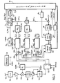
- FIG. 1 The general block diagram of a GPS receiver is given on Figure 1. From the electromagnetic waves received from different GPS satellites (raw signals), block 1001 performs the actual reception, which converts the waves in electrical signals. Next comes a functional block 1002 frequency conversion, then a function block 1003, which corresponds to sampling and quantification.
- Block 1004 corresponds to the correlations, as well as to the others time measurements and demodulations carried out on the carrier.
- a correlation of the code received with the replica local code generator corresponding to the satellite to acquire will to determine the arrival time of the received wave, and find the slow modulation it carries.
- the two correlator input codes are in coincidence or almost (within the above triangular answer)
- an output voltage is obtained; otherwise, the exit from correlator is zero, ie noise.
- it's in accumulating this tension for a while that one gets meaningful information about the coincidence taking into account that the received signal is below the noise in the receiver input band), and that you can find the navigation message.
- such systems are content with a low transmission power, corresponding to a reception level located below the noise level.
- block 1004 has two control loops.
- a carrier servo loop "continues” the carrier frequency and phase, as received.
- a code servo loop "pursues” synchronism between the code received and the corresponding local replica.
- the carrier loop therefore stores the estimated total phase ⁇ i (upper case phi) of the carrier.
- total phase here includes the phase shift suffered by the carrier during the wave travel time and the Doppler effect due to the relative satellite / receiver movement.
- the frequency difference f i corresponds to a Doppler shift, therefore to a relative speed; this is why it is also called "speed".
- the code loop stores an estimated delay of the code ⁇ and i , relative to the local clock.
- the receiver can then take different states, which corresponds to the test functional unit 1100 called "referral according to the state of the line of sight".
- the test functional unit 1100 called "referral according to the state of the line of sight".
- the chase phase 1106 On the other hand, if a collision has already been established, and that we have already gone before in pursuit phase, but synchronism has been lost, we will then be able to re-hook as indicated in 1107. This re-hanging can take into account data coming from sensors outside the GPS receiver, as indicated in 1110.
- block 1120 applies triangulation techniques, which determine the position and speed of the GPS receiver. We therefore obtain a position vector P and a velocity vector V.
- the position coordinates are defined compared to a reference ellipsoid known as WGS 84 (World Geodetic System), and different from the geoid.
- block 1120 To determine receiver position, block 1120 must also calculate an estimate of "clock bias", ie time offset between receiver clock and "time GPS ", which is the general (reference) time of the system common to all satellites.
- a first class of means concerns aerials.
- a good rejection of spurious signals in reverse bias can be provided by helical type antennas, which attenuate the power of multiple paths that have undergone odd number of reflections.
- Mass plans or plans absorbents can be placed under the antennas to attenuate the effect of reflections coming from the ground, or else in a grazing incidence situation.
- antennas with annular structure more precisely called “choke ring”, which constitute alveolar systems forming traps. You can still use antennas beam formation, with directional directional diagram, so to rule out multiple unwanted routes, or at least mitigate.
- multi-antenna systems which are based on the spatial decorrelation of multiples routes, in order to eliminate these.
- Document FR-A-2 698 966 describes another technique consisting in analyzing the front edge of the correlation peak, note that multiple (physical) journeys are always behind on the direct route, and that the front before is little or not distorted. This results in an improvement of the behavior of the receiver.
- the above methods aim to detect multiple paths, and, for some, to partially overcome it.
- the Applicant preferred to focus on receiver arrangements which allow detection of multipath, to prevent the receiver from using wrong measurements to locate (or use these wrong measurements for other purposes). Redundancy of available measures and the low probability of observing multiple paths simultaneously on multiple lines of sight therefore allow, with minimal material investment, significantly increase the quality of positioning.
- FIG. 2 is a more diagram detail of such a receiver, limited to one satellite channel to simplify.
- the receiver starts with an antenna 101 and a stage of high frequency 102 (block 1001 of FIG. 1). Comes next an amplifier 103, the assembly operating on a band which here is 20 MHz, at a frequency of 1575.42 MHz, in the example chosen. In general, the bandwidth in high frequency is between around 2 MHz and a few tens of MHz.
- a mixer 105 receives the output of the amplifier 103, as well as a 1400 MHz local signal from a local oscillator 107; it outputs a useful analog signal of a frequency of 175.42 MHz. This signal is applied to a filter bandpass 109, centered on 175.42 MHz, with a response of +/- 10 MHz at -3 dB, and +/- 25 MHz at -15 dB.
- Block 1002 of Figure 1 corresponds to these bodies 104 to 109, to which can add amplifier 103.
- the filter 109 is followed by an amplifier 110, then by a analog-to-digital converter 112, the output of which is useful signal, this time in digital form.
- the amplifier 110 is preferably of variable gain, its gain being controlled according to the signal level at conversion, in order to optimize the number of significant digits in converter output (2 bits).
- a clock signal generator 20 produces the different clock signals useful to the receiver, and which are, except otherwise mentioned, all linked together. So this generator 20 provides for example a frequency of 20 MHz, which is used to pilot (by multiplication) the local oscillator 107. This the latter includes a voltage controlled oscillator (VCO) operating at 20 MHz, and fitted with a locking loop phase (PLL) on this 20 MHz pilot frequency. From the output of the oscillator, frequency generators provide the frequency of 100 MHz which clock the sampling within the analog-to-digital converter 112, and the other useful frequencies of 1400 MHz and 25 MHz, essentially.
- VCO voltage controlled oscillator
- PLL locking loop phase
- the analog signal has a frequency of 175.42 MHz. he is subsampled at 100 MHz, which is equivalent to one frequency transposition to 200 MHz.
- the converter output analog-digital 112 can therefore be considered as a digital signal centered on 24.58 MHz. Expressed on 2 bits, this digital signal, which here includes 4 samples per period, is applied to a complex sampler 120, detailed in figure 3.
- the sampler includes at 121 a transposer of 420 kilohertz single sideband frequency, reducing the working frequency at exactly 25 MHz (24.58 + 0.42).
- the signal from this block 121 is applied to two operators 123I and 123Q clocked respectively by clocks H25M-I and H25M-Q, at 25 MHz, in quadrature of one another.
- These operators 123 are arranged to provide digital band signals base, expressed on 4 bits, namely respectively a signal in phase (output I), and a quadrature signal (output Q).
- Block 1003 of FIG. 1 comprises the assembly which goes from analog / digital converter 112, preceded by sound variable gain amplifier 110, up to the sampler digital 120.
- the two outputs I and Q of the digital sampler complex 120 are distributed in three ways (block 1004 of the figure 1). These three ways are distinguished by the letters A, B and C, in correspondence of the three correlations also denoted A, B and C, with which three shifts are associated possible pseudo-random code determining the satellite to continue.
- track B is "differential", that is to say that she works on the difference between two replicas of the same pseudo-random code, temporally spaced from each other around the offset associated with this channel B.
- Channel C can be normal (code C1), or differential (code C2).
- Figure 4 details, by way of example, channel A, which appears above in Figure 2.
- the signals in phase I and in quadrature Q are applied to two correlators respectively digital 311A and 312A, also receiving the code A, and whose outputs go jointly to a demodulator carrier 32A.
- the correlator output 311A (4 bits) is applied first to a summator 321, which accumulates on 250 digital samples (9 bits). This cumulation is applied to two digital multipliers 322 and 323, receiving COSinus information respectively and SINus of the carrier phase (P_PHI), each expressed on 6 bits. The respective results, noted Icos and Isin, are expressed on 9 bits.
- the scheme is the same for the signal Q (imaginary part), with the correlator 312A (4 bits), the summator 331, and the two digital multipliers 332 and 333, including the respective results, noted Qcos and Qsin, are expressed on 9 bits.
- the main exits of track A include an I_A signal, supplied by a digital adder 325 which builds Icos + Qsin, on 10 bits, what a 327 summator accumulates on 16 bits, and a signal Q_A, supplied by a digital subtractor 335 which builds Qcos - Isin, on 10 bits, what a summator 337 accumulates on 16 bits.
- the accumulations in 327 and 337 are done on 100 or 200 samples, switchably, which corresponds to a integration time of 1 or 2 milliseconds (time base at 1 kHz or 500 Hz). Indeed, starting from around 25 MHz, we have accumulated on 250 times 100 or 200 samples digital.
- the output of the adder 325 is applied to a adder 341, operating on 50 samples.
- the sign bit from the output of the summator 341, available every 0.5 ms, is stored and serialized in memory 342 to provide 2 or 4 successive sign information, depending on whether works at 1 kHz (1 ms) or 500 Hz (2 ms).
- This information of sign noted SIGN_IA_2K, corresponds to the slow modulation carrying state data, "ephemeris" and "almanac", forming the navigation message.
- Carrier oscillator 71 operates at the H100K rate (100 kHz). Its P_PHI output, representative of the carrier, on 7 bits, feeds a sine-cosine generator 75, also pulsed at the rate H100K, and providing over 6 bits the respective signals COSinus and SINus of the phase of carrier, which go to the carrier demodulators 32 already cited.
- the carrier oscillator 71 adjusts its P_PHI phase, but also, each time it changes modulo 2 ⁇ , by providing increment information or decrement of a phase turn to a circuit 72 which accumulates then, on 16 bits, the number of P_DF turns that the carrier, ie the entire part of its total phase.
- the fractional part of the total phase, on 16 bits, is the aforementioned carrier phase P_PHI.
- the set P_DF and P_PHI goes to management / decision unit 90.
- the code oscillator 81 also a controlled oscillator digital, is pulsed by a clock at the frequency H25M (25 MHz). Its output, on 1 bit, feeds a code generator 85. IT also provides chip fraction information C_PHI (or "phase code”), on 16 bits, which is returned to management-decision unit 90 (operation).
- C_PHI chip fraction information
- the numerical control of the code oscillator 81 is defined on 32 bits by the output of an adder 80, one of which input receives a CV signal, at a frequency of 1.023 MHz, which is the base rate of the pseudo-random code.
- the other input of this adder 80 receives a correction (help in speed), coming from unit 59 already mentioned.
- This DVCo correction corresponds to the output of the code loop DLL 50, "helped" by the output of the PLL carrier loop 40.
- Unit 59 converts DVCa correction into the same time unit as for DVCo correction.
- the conversion ratio K of unit 59 corresponds to the ratio respective code and carrier frequencies, i.e. 1540 (1575.45 divided by 1.023).
- the code generator 85 receives information time setting from table 84, filled in control of the management-decision unit 90 as a function of the PRN code number relating to the satellite concerned.
- a shift register 890 of 63 boxes (-31.0, + 31), is powered by the code from the code generator 85, sampled at 25 MHz. Each box in register 890 therefore represents a period of this clock at 25 MHz, or 40 ns (nanoseconds), or 1/25 chip. The output of 5 boxes among the 63 possible will generate replicas A, B and C.
- a pre-programmed output 891, coming from the central box 0, will represent the entry of the centered point lane, or lane A, coded on 1 bit.
- the other outputs 892 E and 892 L, as well as 893 E and 893 L, are programmable two by two symmetrically with respect to box 0. They are combined in logical operators 894 and 895, which perform a logical subtraction and a divide by two, and respectively provide the inputs correlators of channels B and C, coded on 2 bits.
- the local replica of channel B corresponds to a position of outputs 892 E and 892 L at +/- x fractions of 1/25 chip, hence a spacing or spacing of 2.x / 25 chip (between the two codes Advance E and Delay L which we differentiate).
- the local replica of channel C corresponds to a position of outputs 893 E and 893 L at +/- y fractions of 1/25 chip, resulting in a spacing or spacing of 2.y / 25 chip.
- Channel C can be formed either by the output, called C2, of 895 (of the form 893 E minus 893 L), or by the outlet of 893 E or that of 893 L (outputs indifferently noted C1).
- the correlator response has a triangular shape, with maximum synchronism, and the width of the base of the triangle is +/- Dmc, or +/- 1 chip.
- the result of the correlation corresponds to what would give the difference between two correlations made respectively with the two components of the replica differential: for example, the correlator output of the channel B with the local replica (892 E - 892 L) corresponds to the difference between the outputs of two correlations made respectively with local replicas available in 892 E and 892 L.
- the time difference between 892 E and 892 L (by example) is called spacing, or deviation window, or still devometer.
- the two correlations we build so the difference each have a triangular response of width +/- 1 chip at the base.
- this composition provides, in the center, a substantially responsive response area linear, which goes through zero at the midpoint of the differential correlation window. It is this area which allows the control of a temporal slaving, like the does track B.
- a known phase known as acquisition or hanging allows to bring the punctual code of channel A close enough to synchronism with the signal received to get a response (a spike) in the correlators 311A and 312A, and therefore I_A and Q_A signals occur finding it above the noise.
- This can be done by research systematic, and / or taking into account information that is already available, from external sources or due to previous operation of the GPS receiver (re-hanging).
- We can decrease the systematic search time by using in parallel the code A, as well as one and / or the other of the 893 E and 893 L versions of code C (possibly adapt the lane B, to make it play at this stage the same role as the track C).
- This systematic research can be done by all the ways known to those skilled in the art.
- a signal D_B which will be discussed later with reference in FIG. 6 (output from the stage 50 of ecometometry with PLL phase locked loop), controls the code loop until obtaining a temporal setting at +/- one tenth of a chip, or better, by way B.
- the rough positioning of the code loop (at +/- 1 chip) can be found using a deviation signal D_C, which will also be discussed later in reference to FIG. 6 (output from the stage 60 of ecometometry).
- these two quantities P_DF and P_PHI together define a fine measure of the deviation time on channel A, using the carrier frequency, in the vicinity of synchronism on the code received. This measure fine is called pseudo carrier distance (or "pseudo range” carrier).
- pseudo carrier distance or "pseudo range” carrier.
- the setpoint value of the carrier oscillator is provided by the management / decision unit 90 in function an estimated Doppler ("Dop. Port").
- the magnitude of the deviation corresponding to the output of stage PLL 40 is applied to the carrier oscillator, as well as register 59 and the digital adder 80, to "help in speed" the code loop controlled by the components in phase I_B and in quadrature Q_B of channel B.
- the code loop is by example a 2nd order loop with a bandwidth of 1 Hz, assisted in speed by an output of the tracking loop carrier.
- the estimated phase of the carrier ⁇ i is a total phase, that is to say that it may include a frequency offset of a certain number of turns, as we have seen. It is therefore simpler to decompose it into a frequency f i , and a phase proper, that is to say modulo 2 ⁇ , denoted ⁇ i .
- GPS receivers already include means for decision to rule out a line of sight that provides a questionable measure.
- the decision to invalidate a line of sight is based for example on the fact that the carrier loop does not does not remain stably in tracking mode phase (IPPP logic signal), or that the code loop does not not find its balance (IQPC signal).
- IPPP logic signal IPPP logic signal
- IQPC signal IQPC signal
- the choice of signals used as a basis for this largely depends on the design of carrier and code tracking loops. If the line of target is invalidated, the receiver does not validate the estimates corresponding, and works only with the estimates available for other lines of sight. He can try a new hanging or re-hanging phase with the same satellite, or rather search for another satellite more auspicious.
- the Applicant has observed that the presence of multiple unwanted journeys acts on these three characteristics and may distort the measurements generated by the receiver for a given satellite.
- the position error can go up to 175 meters (three-dimensional). This mistake falls from 1 to 10 meters in differential GPS; in interferometry differential (geodesy, attitude determination), the error becomes a few centimeters, still in mode three-dimensional.
- the class of precision sought is much better, when for example uses a differential GPS in code or in phase, or in short base interferometry, the phenomenon of multiple journeys even become a major obstacle, which compromises the expected accuracy of the GPS receiver.
- the Applicant has sought techniques that identify or detect questionable measures due to multiple journeys, without a priori seeking to infer corrections from these questionable measures.
- the techniques proposed here involve a double analysis, namely a frequency analysis, carried out at carrier loop level, and a time analysis, done in conjunction with the code loop, and using an additional correlation channel.
- the frequency analysis aims first to detect multiple paths whose component Doppler differs from that of the direct path, while temporal analysis completes it by treating the detection of multiple paths including the Doppler deviation with the direct path is weak or very weak.
- block 38A designates a transformation circuit Fast Fourier, or FFT, with input signals I_A and Q_A.
- This fast Fourier transformation takes place on 512 points at 1 millisecond, for example.
- the analysis circuit 39A receiving the output of the Fourier transformation goes perform different operations which will be described in more detail far, in connection with the management / decision unit 90 (in practical, circuit 39A is incorporated in unit 90).
- monitoring frequency includes a first test 2001, which consists of examine whether the signal level P at the input is normal, i.e. equal to the thermal noise KTBF, to a tolerance near. If this condition is not met, it is a general abnormality - serious dysfunction likely to carry on different parts of the receiver - so in principle not diagnosable in terms of multiple paths.
- the rest of the mechanism involves logical signals, such IQPP, notably emanating from the tracking loop carrier 40.
- the 2020 test (FIG. 7) relates, for each of the boxes except the central box of index c, to the fact that the power PBS i crosses the threshold BT0 in at least one of the FFT boxes of the safety band (see for example Figures 8B and 8D). If no such crossing exists (outside the central box), step 2021 finds that the phase and speed data are valid, the status of the distance data remaining to be determined. If, on the contrary, PBS i exceeds the threshold BT0 in at least one of the boxes considered in the FFT (apart from the central box), step 2022 establishes that the phase data are invalid and that the distance data are in principle invalid, the fate of the speed data remains to be specified.
- step 2021 also searches if, in at least one of the sideband boxes, PBL j exceeds the threshold BT0. If the answer is no, step 2032 establishes that the distance data are valid, and we go directly to the end of 2090 step. Indeed, in this case, all the boxes of the FFT except the central box are below the BT0 threshold.
- step 2033 establishes that the distance data are in principle invalid, subject to the possible correction which will be discussed below.
- a test 2041 compares the level in each of the boxes in the band security, except the central box, at threshold BT1 which is greater than BT0. This test therefore checks whether there is a crossing high threshold level in the safety band except the central box.
- step 2042 determines that the data are also invalid, and we go to step end of 2090.
- step 2043 admits that the data of speed are valid, as long as the logic signal IRBP indicates that the rejection carried out by the carrier is correct.
- FIG. 7 illustrates a variant optional, which we will come back to later.
- the output of the stage 50 of ecometometry with phase locked loop (PLL) of the code loop provides a difference magnitude D_B.
- Channel C receives the C2 response (893 E minus 893 L); she has so the same center as channel B, but more spacing large, the time difference between 893 E and 893 L being greater to that between 892 E and 892 L.
- One unit of deviation 60 (identical to unit 50, except for the spacing between doors that subdivide the spacing) builds a deviation quantity D_C, from the components in phase I_C and in quadrature Q_C available at the output of channel C.
- the time analysis includes monitoring the module of the signal D_C (or its square), and / or monitoring the module of the signal Z (or its square).
- FIG. 10 shows that these modules ⁇ D_C ⁇ and ⁇ Z ⁇ are compared (901.902) with respective thresholds M C and M Z.
- a decision module 910 uses the crossing of the thresholds to construct an indication of the presence of multiple paths, as will be seen below. Although it is currently preferred to use the two signals D_C and Z, it is conceivable to use only one of these two signals, at least for certain applications. In practice, the elements 901, 902 and 910 are part of the management / decision unit 90.
- the invention does not exclude monitoring of the module of the signal D_B (or of its square), in particular in a receiver that would not have a C channel.
- the deviation width channel B can then be increased.
- the signals D_B and D_C result from the integration on a large number of individual correlations. This integration can range from a few hundred milliseconds to a few seconds, depending on the dynamics of the multipath phenomenon for the application considered. In addition, the spacing of channel C being significantly wider than that of channel B, the contribution of noise in the signal D_C is significantly higher than that of noise in the signal D_B.
- x and y are chosen to correspond to spacings of 0.2 chip and 1 chip, respectively, for channels B and C.
- the value 2x can go down to about 0.1 chip; as for y, we observes a fairly rapid attenuation beyond 1 chip. Of preferably, it is taken as large as possible relative to x.
- Channel B feeds the distance tracking (on the code), via the dot product and the normalization obtained from track A. After a more or less long transient regime, the enslavement achieved by the code loop found in always a position of equilibrium, at least when works on the basis of the dot product.
- the magnitude D_B is zero, excluding noise, when the control achieved by the code loop is stabilized (as recalled inside block 50).
- the quantity D_C is also zero, apart from noise, but under reserves that the window or time difference meter of channel C, spacing 2.y large from 2.x, receive only the direct route, too.
- the tracking is said to be canonical when there is only a direct path, and nothing else (except for noise) between the transmitter (the satellite) and the receiver.
- the direct signal is associated with a delay ⁇ D (with respect to the local time base) which is normally close to the center ⁇ and of channel B. This signal will have the same contributions on channel B and on the lane C, because it both enters the windows of these two lanes.
- ⁇ D_C ⁇ a threshold M C , the crossing of which will be indicative of the presence of an additional path.
- This threshold can be fixed in relation to the expected noise level in channel C, and taking into account an admitted risk of error ("probability of false alarm” or Pfa).
- the threshold is proportional to the integration time.
- the Pfa is 14%, if we accept to reject on average a line of sight for each set of 7 simultaneous measurements usable for calculate a positioning. We can then deduce by numerical calculation the threshold to be applied to channel C, account given the operating parameters of the receiver.
- ⁇ D_C ⁇ exceeds M C , the management / decision unit 90 will therefore decide to invalidate the current line of sight.
- ⁇ D_B ⁇ for channel B, as already indicated.
- the difference Z does not involves only noise.
- the curve is naturally symmetrical with respect to the point (0,0), for the negative values of d RD (in certain applications, it can happen that a "reflected" signal - or assimilated, in principle a decoy signal - arrives before the "direct” signal).
- a threshold M Z suitably chosen to the signal Z makes it possible to identify the presence of multiple paths in channel C and / or B, and to draw the consequences thereof for the proper functioning of channel B, therefore to the code loop it controls.
- One way - without limitation - to set this threshold M Z is to take the threshold M C provided for the signal D_C itself, modified in proportion to the ratio of the respective noise levels of D_C and Z (80%, if the noise in Z is 20% below the noise in D_C).
- the signal ⁇ Z ⁇ is therefore also a good indicator of the existence of multiple paths.
- the ITPP signal can be provided by the fact that frequency detection gives the main signal not in the central box, but in one of the neighboring boxes (or straddling boxes adjacent neighbors).
- the structure with double devometer proposed is therefore particularly interesting in itself for this purpose.
- Results of frequency analysis and / or analysis are used to selectively discard the measurements (a "line of sight", or more) identified as partially or completely questionable according to the present invention.
- the indicators provided here therefore complement advantageously indicators (independent of multiple paths) which are already used in receivers known to spread a line of sight providing a questionable measurement.
- the time analysis gives a very interesting additional means to detect the presence of reflected paths. On this detection, we invalidate all measurements corresponding to the line of sight considered.
- frequency analysis makes it possible to separate reflected signals of the direct signal when the distance from the receiver reflector is variable (deviation Doppler not zero). This is for example the case of an airplane in flight ascending or descending with respect to reflective ground, or the case of a land vehicle moving alongside of a potentially reflecting surface, not parallel to the vehicle speed vector.
- the temporal analysis which has just been described gives information where the frequency analysis is little efficient, i.e. with a low or zero Doppler difference between the direct signal and the reflected signal (s). It is by example the case for an aircraft in horizontal flight with respect to a reflective floor, or for a stationary receiver (fixed with respect to reflective surfaces).
- Frequency analysis is particularly effective for the multiple diffuse paths, and, as such, interesting to she alone. More precisely, the diffuse paths play on the form of the code correlation function of a way that depends on the speed of the receiver carrier, hence the need for a short analysis time. In that case, frequency analysis is fully effective.
- test 2051 which starts from a logical variable IPS (Indicator of Return Ground), which indicates whether the altitude and elevation allow the observation of multiple paths on the current line of sight.
- IPS Intelligent of Return Ground
- This operation must take into account the following relationship: 2.H.sin ⁇ ⁇ Dmin, where H is the altitude, ⁇ is the angle of incidence of the waves on the receiver with respect to the horizontal ("elevation"), and ⁇ Dmin represents a ceiling difference between direct signal and reflected signal, beyond which the disturbance no longer causes significant distance bias.
- This quantity ⁇ Dmin is established as a function of the spacing of the differential correlator used in channel B; ⁇ Dmin typically corresponds to 250 meters in the example described.
- H and ⁇ can be determined, if necessary using the instruments on board an aircraft.
- a sufficient approximate value of H can be obtained by using all the measurements (even those polluted by multiple paths).
- ⁇ is precisely calculable, because the positioning obtained with all the measurements will be false at most from 100 to 200 meters, which is angularly negligible, given the minimum satellite-receiver distance of 20,000 km.
- H is the height relative to the geoid, and that it is accessed only by having in memory the height of the geoid relative to WGS 84 in the area overflown, for example 50 meters in the ocean. Atlantic, opposite the Austin.
- This test relates to the existence of FFT boxes with crossing of the threshold BT0 (apart from the central box), but remaining isolated. This isolated character is advantageously determined by the fact that, for each square crossed, the two adjacent lower boxes and the two upper boxes adjacent are not the subject of a crossing noise level BT0. If the answer is yes (isolated box), the IPR signal is true, and we go to the end of 2090 stage. This corresponds in particular to the case illustrated in Figure 8G, which is also found in 8D and 8C.
- test 2054 checks to see if there is a single series of non-isolated boxes, the subject of a crossing of the BT0 threshold, and retaining a contrast important between the direct signal and the one contained in each of these boxes.
- the center frequency definable on all of these boxes crossing the BT0 threshold must remain relatively close to the box central. If all this is false, we go directly to the end step 2090, the distance remaining invalid.
- step 2055 it is conceivable at step 2055 to correct the distance from the integral of the energy in this series or "continuum" of boxes surrounding the central box, and having a relatively close center frequency that of the central box. This situation corresponds to diagram of FIG. 8B (the contrast is insufficient on the Figure 8F).
- the invention is not limited to the embodiment described, especially with regard to the three-way receiver from which the invention is described here. A number superior of tracks is not excluded. In some cases of figure, we could consider reversing the roles of channels B and C. One could also consider that these channels do not have the same center (between them, or as channel A), especially to take into account the fact that the reflected paths are natural after the direct route.
- the invention can be extended to other radio positioning systems (or more generally of radio navigation) than GPS, whether based on satellites, like the GLONASS system, or terrestrial.
- GPS Globalstar Satellite System
- the satellites use different carrier frequencies, modulated in bi-phased by a pseudo-random code which is common to them; a person skilled in the art will know how to make the adaptations required for the implementation of the present invention.
- waves are used here to locate the receiver; an application variant consists in re-issuing waves marked in time according to the data of time obtained by reception.
Abstract
Un récepteur de signaux à porteuse modulée munie d'un marqueur temporel à code pseudo-aléatoire, notamment pour la radionavigation, comprend des modules à coïncidence comportant chacun des moyens de mémoire chronométrique (71-75,80-89) qui réceptionne un signal utile, stockent comme données de calage temporel des estimées de calage de code (C_PHI) et d'état de porteuse en fréquence (P_DF) et phase (P_PHI), et en tirent, avec une horloge locale, une image locale de porteuse et au moins une réplique locale du code, pour le signal concerné, et des asservissements de code et de porteuse (40,50,59), corrélant le signal utile et la réplique locale de code à l'aide d'un signal d'écart de fréquence et de phase (DVCa) entre la porteuse du signal utile et l'image de porteuse. Il comprend en outre des moyens de transformation de Fourier recevant le signal d'écart (DVCa) et des moyens de gestion/décision (90) qui invalident les données de calage temporel lorsque la transformation de Fourier indique la présence d'énergie en dehors du voisinage d'une raie centrale de coïncidence. <IMAGE>A modulated carrier signal receiver fitted with a pseudo-random code time marker, in particular for radio navigation, comprises coincidence modules each comprising chronometric memory means (71-75,80-89) which receives a useful signal , store as time calibration data estimates of code calibration (C_PHI) and of carrier state in frequency (P_DF) and phase (P_PHI), and derive therefrom, with a local clock, a local image of carrier and at least a local code replica, for the signal concerned, and code and carrier slaves (40,50,59), correlating the useful signal and the local code replica using a frequency difference signal and phase (DVCa) between the carrier of the useful signal and the carrier image. It further comprises Fourier transformation means receiving the deviation signal (DVCa) and management / decision means (90) which invalidate the timing data when the Fourier transformation indicates the presence of energy outside the neighborhood of a central line of coincidence. <IMAGE>
Description
L'invention concerne la radionavigation, qui utilise le temps de propagation d'une onde électromagnétique à marqueur temporel entre un émetteur et un récepteur.The invention relates to radio navigation, which uses time propagation of a marker electromagnetic wave between a transmitter and a receiver.
Dans les systèmes de navigation récents, le marqueur temporel de l'onde porteuse est du type pseudo-bruit répétitif; on utilise en pratique un code pseudo-aléatoire. A la réception, le temps de propagation de l'onde se manifeste à la fois par un décalage temporel du code pseudo-aléatoire et par un décalage de phase de la porteuse. En présence d'un mouvement relatif sur l'axe émetteur/récepteur (ligne de visée), il s'y ajoute un décalage de fréquence de la porteuse, dû à l'effet Doppler.In recent navigation systems, the time marker of the carrier wave is of the repetitive pseudo-noise type; we in practice uses a pseudo-random code. At the reception, the propagation time of the wave is manifested by both a time offset from the pseudo-random code and by a carrier phase shift. In the presence of a movement relative on the transmitter / receiver axis (line of sight), there adds carrier frequency offset due to the effect Doppler.
Différentes sources d'erreur existent: certaines, liées à la traversée de la troposphère ou de l'ionosphère, ou bien à la variation de conductivité des sols, affectent de manière générale la vitesse de propagation des ondes; d'autres sources d'erreurs tiennent au fait que le trajet parcouru par l'onde radioélectrique jusqu'au récepteur n'est pas rectiligne, d'autres encore au fait que le récepteur perçoit une combinaison de différents trajets issus de réflexions diverses, généralement dues à des surfaces voisines de l'antenne de réception. C'est ce qu'on appelle les erreurs de trajets multiples: au trajet direct (le plus court) se superposent d'autres trajets indésirés.Different sources of error exist: some, related to the crossing the troposphere or the ionosphere, or at the variation in soil conductivity, so affect general wave propagation speed; others sources of error stem from the fact that the distance traveled by the radio wave to the receiver is not straight, still others to the fact that the receiver perceives a combination of different paths from reflections various, generally due to surfaces close to the receiving antenna. These are called errors of multiple paths: the direct path (the shortest) overlap other unwanted trips.
Dans les systèmes de radionavigation les plus utilisés à ce jour, dits GPS et GLONASS, les émissions proviennent de satellites.In the most widely used radio navigation systems day, known as GPS and GLONASS, the emissions come from satellites.
Actuellement, le problème principal est de combattre les effets des trajets multiples, ainsi qu'en témoigne l'article "Conquering multipath: The GPS accuracy battle", Lawrence R. WEILL, revue GPS World, Avril 1997, pp 59-66. Tel est le but principal de la présente invention. Currently, the main problem is to combat effects of multipath, as shown in the article "Conquering multipath: The GPS accuracy battle", Lawrence R. WEILL, GPS World review, April 1997, pp 59-66. This is the goal principal of the present invention.
L'invention s'applique à un dispositif récepteur de signaux ou ondes radio-électriques, qui portent un marqueur temporel à pseudo-bruit répétitif, du genre code pseudo-aléatoire, en particulier pour la radionavigation.The invention applies to a signal receiving device or radio waves, which carry a time marker with repetitive pseudo-noise, of the pseudo-random code type, in especially for radio navigation.
Un tel dispositif comporte une réception haute fréquence, dont la sortie (ou "signal utile") est distribuée à plusieurs canaux ou modules, dont chacun est affecté à la recherche d'une coïncidence (calage temporel) avec un signal radio-électrique choisi respectif, distingué par son code et/ou par sa fréquence porteuse. Il s'y ajoute des moyens d'exploitation des données de calage temporel fournies par ces modules à recherche de coïncidence (ou plus simplement : module à coïncidence).Such a device includes a high frequency reception, whose output (or "useful signal") is distributed to several channels or modules, each of which is assigned to research coincidence (timing) with a radio signal chosen respective, distinguished by its code and / or by its carrier frequency. There are also means of exploitation time setting data provided by these modules looking for coincidence (or more simply: module at coincidence).
Chaque module à coïncidence comprend d'une part des moyens formant mémoire chronométrique, aptes à recevoir et/ou stocker une estimée de calage de code et une estimée d'état de porteuse en fréquence et phase, ainsi qu'à en tirer, à l'aide d'une horloge locale, une image locale de porteuse et au moins une réplique locale du code, pour le signal radio-électrique concerné. Il comprend d'autre part des asservissements visant à faire coïncider la réplique locale du code avec le code reçu. Ces asservissements comprennent un asservissement de code, opérant par corrélation entre le signal utile et la réplique locale de code, et un asservissement de porteuse, qui travaille à l'aide d'un signal d'écart de fréquence et de phase entre la porteuse présente dans le signal utile et ladite image de porteuse.Each coincidence module comprises on the one hand means forming a chronometric memory, suitable for receiving and / or store a code timing estimate and a state estimate carrier frequency and phase, as well as using a local clock, a local carrier image and at least one local code replica, for the radio signal concerned. On the other hand, it includes slaves to match the local code replica with the code received. These servos include a code slaving, operating by correlation between the useful signal and local code replica, and a servo carrier, working with a deviation signal frequency and phase between the carrier present in the useful signal and said carrier image.
Un tel module à coïncidence peut fournir une indication sur le bon fonctionnement de ses asservissements. On sait en tenir compte d'une part pour le choix de signaux radio-électriques incidents qui donnent des résultats satisfaisants, d'autre part au niveau de l'exploitation des données de calage temporel.Such a coincidence module can provide an indication of the proper functioning of its enslavements. We know in take into account on the one hand when choosing radio signals incidents that give satisfactory results, on the other hand at the level of data exploitation time setting.
Selon un aspect de l'invention, le dispositif récepteur comprend en outre des moyens capables d'effectuer une transformation de Fourier recevant un signal représentatif de l'écart de fréquence et phase de porteuse. A partir de la transformée de Fourier, des moyens de décision peuvent invalider au moins partiellement les données de calage temporel, en particulier lorsque la transformation de Fourier indique la présence d'énergie en dehors du voisinage d'une raie centrale, cette dernière correspondant à la coïncidence.According to one aspect of the invention, the receiving device further includes means capable of performing a transformation Fourier receiving a signal representative of the frequency difference and carrier phase. From the Fourier transform, decision means can at least partially invalidate the calibration data temporal, especially when the Fourier transformation indicates the presence of energy outside the vicinity of a central line, the latter corresponding to coincidence.
On précisera plus loin différentes caractéristiques plus détaillées du fonctionnement de cette surveillance fréquentielle.Different characteristics will be specified later. details of the operation of this frequency monitoring.
Dans un mode de réalisation préférentiel du module à coïncidence, les moyens formant mémoire chronométrique comprennent un oscillateur de porteuse pour définir l'image locale de porteuse, un oscillateur de code, et un générateur d'au moins une réplique locale du code. De leur côté, les asservissements de code et de porteuse comprennent une voie de corrélation ponctuelle, comportant une démodulation selon ladite image de porteuse, et fournissant un signal de coïncidence entre la position temporelle du code dans le signal utile et son estimée, et au moins une voie de corrélation différentielle, comportant une démodulation selon ladite image de porteuse, et fournissant un signal d'écart entre la position temporelle du code dans le signal utile et son estimée. Le signal de coïncidence sert de grandeur d'écart pour une boucle de porteuse à verrouillage de phase, laquelle pilote le générateur d'image locale de porteuse; et le signal d'écart de code sert de grandeur d'écart pour une boucle de code à verrouillage de retard, dont la sortie est combinée à celle de la boucle de porteuse à verrouillage de phase, pour piloter le générateur de répliques de code.In a preferred embodiment of the coincidence module, the chronometric memory means include a carrier oscillator to define the local image of carrier, a code oscillator, and a generator of at least a local replica of the code. For their part, the enslavements code and carrier include a correlation channel punctual, comprising a demodulation according to said carrier image, and providing a coincidence signal between the time position of the code in the wanted signal and its estimated, and at least one differential correlation path, comprising a demodulation according to said image of carrier, and providing a signal of deviation between the position time of the code in the useful signal and its estimated. The coincidence signal is used as the difference quantity for a phase locked carrier loop which controls the local carrier image generator; and the signal code deviation serves as the deviation quantity for a loop of delay lock code, the output of which is combined with that of the phase locked carrier loop, for pilot the code replica generator.
Un autre aspect de l'invention, très intéressant en lui-même, est l'analyse "temporelle". Selon celle-ci, on établit une autre indication de la présence de multiples trajets en utilisant le signal d'écart issu d'au moins une voie de corrélation différentielle. Another aspect of the invention, very interesting in itself, is the "temporal" analysis. According to this, we establish a another indication of the presence of multiple paths in using the deviation signal from at least one channel differential correlation.
Pour mettre en oeuvre l'analyse temporelle, il est actuellement préféré que chaque module à coïncidence comprenne au moins une seconde voie de corrélation différentielle, possédant un espacement différent de celui de la première. On prévoit alors des moyens pour utiliser le signal d'écart issu de cette seconde voie de corrélation, seul et/ou par sa comparaison (différence) avec le premier signal d'écart, en tant qu'indication de la présence de multiples trajets.To implement the temporal analysis, it is currently preferred that each coincidental module understand at minus a second differential correlation path, with different spacing than the first. We then provides means for using the deviation signal from of this second correlation path, alone and / or by its comparison (difference) with the first deviation signal, in as an indication of the presence of multiple paths.
On précisera plus loin différentes caractéristiques plus détaillées du fonctionnement de cette surveillance ou analyse temporelle.Different characteristics will be specified later. details of the operation of this monitoring or analysis temporal.
D'autres caractéristiques et avantages de l'invention apparaítront à l'examen de la description détaillée ci-après, et des dessins annexés, sur lesquels:
- la figure 1 est le schéma de principe général d'un récepteur GPS;
- la figure 2 est le schéma plus détaillé d'un mode de réalisation particulier de récepteur GPS, auquel l'invention peut s'appliquer;
- les figures 3 et 4 illustrent deux détails du récepteur de la figure 2;
- la figure 5 est un schéma équivalent permettant de mieux comprendre la génération des répliques locales appliquées à des corrélateurs dans le récepteur des figures 2 à 4;
- la figure 6 est une vue partielle illustrant l'une des caractéristiques de la présente invention;
- la figure 7 illustre le mécanisme associé à la surveillance fréquentielle selon l'invention;
- les figures 8A-1 à 8G-1 sont des diagrammes fréquentiels illustrant différentes situations de multiples trajets, spéculaires et/ou diffus;
- les figures 8A-2 à 8G-2 sont des diagrammes de transformées de Fourier, équivalents respectivement aux diagrammes des figures 8A-1 à 8G-1;
- les figures 9A à 9C sont trois diagrammes temporels illustrant respectivement les sorties des deux voies de corrélation différentielle B et C du récepteur des figures 2 à 4, ayant des espacements différents, et le signal différence entre ces deux sorties ; et
- la figure 10 illustre schématiquement les moyens de base de l'analyse temporelle selon l'invention.
- Figure 1 is the general block diagram of a GPS receiver;
- FIG. 2 is the more detailed diagram of a particular embodiment of a GPS receiver, to which the invention can be applied;
- Figures 3 and 4 illustrate two details of the receiver of Figure 2;
- FIG. 5 is an equivalent diagram making it possible to better understand the generation of the local replicas applied to correlators in the receiver of FIGS. 2 to 4;
- Figure 6 is a partial view illustrating one of the features of the present invention;
- FIG. 7 illustrates the mechanism associated with frequency monitoring according to the invention;
- FIGS. 8A-1 to 8G-1 are frequency diagrams illustrating different situations of multiple paths, specular and / or diffuse;
- FIGS. 8A-2 to 8G-2 are diagrams of Fourier transforms, equivalent respectively to the diagrams of FIGS. 8A-1 to 8G-1;
- FIGS. 9A to 9C are three time diagrams respectively illustrating the outputs of the two differential correlation channels B and C of the receiver of FIGS. 2 to 4, having different spacings, and the difference signal between these two outputs; and
- FIG. 10 schematically illustrates the basic means of the temporal analysis according to the invention.
Les dessins annexés sont, pour l'essentiel, de caractère certain. En conséquence, ils pourront non seulement servir à mieux faire comprendre la description, mais aussi contribuer à la définition de l'invention, le cas échéant.The attached drawings are essentially of a character certain. As a result, they will not only be used to make the description better understood, but also contribute the definition of the invention, if applicable.
La radionavigation utilise surtout les codes pseudo-aléatoires, bien que l'on puisse concevoir d'autres types de marqueurs temporels assimilables à un bruit. Un code pseudo-aléatoire est un enchaínement répétitif d'une séquence pseudo-aléatoire. On l'appelle aussi code à bruit pseudo-aléatoire, ou bien code PRN (de l'anglais "Pseudo Random Noise").Radio navigation mainly uses pseudo-random codes, although other types of markers can be designed temporal similar to noise. A pseudo-random code is a repetitive sequence of a sequence pseudo-random. It's also called pseudo-random noise code, or PRN code (from the English "Pseudo Random Noise ").
Une façon d'engendrer une séquence pseudo-aléatoire est décrite dans FR-A-2 248 517, notamment en référence à ses figures 1 à 3. Une séquence pseudo-aléatoire peut être considérée comme une suite de bits, parcourue avec une période d'horloge bien définie. L'expression appelée "moment de code", ou plus fréquemment "chip", désigne un bit de la séquence, et, par extension, la durée (Dmc) d'un tel bit.One way to generate a pseudorandom sequence is described in FR-A-2 248 517, in particular with reference to its Figures 1 to 3. A pseudo-random sequence can be considered as a series of bits, traversed with a well defined clock period. The expression called "moment of code ", or more frequently" chip ", denotes a bit of the sequence, and, by extension, the duration (Dmc) of such a bit.
Une séquence pseudo-aléatoire possède la propriété suivante: sa fonction d'autocorrélation est nulle, sauf au voisinage du décalage temporel nul, où elle prend une allure triangulaire, avec un maximum en cas de synchronisme. La largeur de la base du triangle est de +/- Dmc (voir la figure 13A de FR-A-2 248 517 et la description correspondante). La valeur zéro indique un niveau de réjection qui dépend de la longueur du code. Il en découle que l'on peut engendrer une variété de séquences pseudo-aléatoires de même durée ou "époque" (Dprn), et dont les fonctions d'intercorrélation sont nulles.A pseudo-random sequence has the following property: its autocorrelation function is zero, except in the vicinity of the zero time offset, where it takes a triangular shape, with a maximum in case of synchronism. The width of the base of the triangle is +/- Dmc (see Figure 13A of FR-A-2 248 517 and the corresponding description). The value zero indicates a level of rejection which depends on the length of the coded. It follows that one can generate a variety of pseudo-random sequences of the same duration or "epoch" (Dprn), and whose intercorrelation functions are zero.
Dans le système GPS, différents satellites émettent des porteuses, à une fréquence d'environ 1 gigahertz, modulées par des codes pseudo-aléatoires respectifs, et spécifiques à la fois du satellite et de la fréquence porteuse. Plus précisément, un satellite donné émet actuellement deux porteuses, munies de codes PRN respectifs notés "C/A" (pour "Coarse Acquisition" ou "Clear Acquisition"), et "P" (pour "Precise"). Le premier code C/A est public, alors que le second code noté P, présente une version notée P(Y), intrinsèquement plus précise que le code C/A, mais soumise à un encryptage qui reste confidentiel. La polarisation de l'onde porteuse est circulaire droite.In the GPS system, different satellites transmit carriers, at a frequency of about 1 gigahertz, modulated by respective pseudo-random codes, and specific to both the satellite and the carrier frequency. More specifically, a given satellite is currently transmitting two carriers, with respective PRN codes marked "C / A" (for "Coarse Acquisition" or "Clear Acquisition"), and "P" (for "Precise"). The first C / A code is public, while the second code denoted P, presents a version denoted P (Y), intrinsically more precise than the C / A code, but subject to encryption which remains confidential. The polarization of the wave carrier is circular right.
Comme les récepteurs GPS d'aujourd'hui utilisent surtout le code "C/A", non brouillé, la suite de cette description est limitée à ce code et à la porteuse correspondante, à 1575,42 MHz, qui comporte deux modulations :
- une modulation numérique rapide par inversion de phase (BPSK pour Bi-Phase Shift Keying) selon un code pseudo-aléatoire spécifique de 1023 bits, pulsé à 1,023 MHz, avec Dprn = 1 ms, et
- une modulation numérique beaucoup plus lente (50 Hz) définissant des données d'état du satellite, que l'on appelle "message de navigation".
- a fast digital modulation by phase inversion (BPSK for Bi-Phase Shift Keying) according to a specific pseudo-random code of 1023 bits, pulsed at 1.023 MHz, with Dprn = 1 ms, and
- a much slower digital modulation (50 Hz) defining satellite state data, which is called "navigation message".
Il est clair que l'invention ne se limite pas à l'application au seul code C/A.It is clear that the invention is not limited to the application only C / A code.
Les satellites GPS ont une référence de temps commune. Le message de navigation d'un satellite ("éphémérides" et "almanachs") comprend notamment la dérive de son horloge propre (par rapport à une référence de temps), et les éléments nécessaires pour calculer sa position (paramètres d'orbite). En bref, les paramètres de leur orbite étant connus, les satellites sont à considérer comme des postes émetteurs dont les positions sont déterminables.GPS satellites have a common time reference. The satellite navigation message ("ephemeris" and "almanacs") understands in particular the drift of its own clock (compared to a time reference), and the elements necessary to calculate its position (orbit parameters). In short, the parameters of their orbit being known, the satellites are to be considered as transmitting stations whose positions are determinable.
Le schéma synoptique général d'un récepteur GPS est donné sur
la figure 1. A partir des ondes électromagnétiques reçues de
différents satellites GPS (signaux bruts), le bloc 1001
réalise la réception proprement dite, qui convertit les ondes
en signaux électriques. Viennent ensuite un bloc fonctionnel
1002 de conversion de fréquence, puis un bloc fonctionnel
1003, qui correspond à l'échantillonnage et à la quantification.The general block diagram of a GPS receiver is given on
Figure 1. From the electromagnetic waves received from
different GPS satellites (raw signals),
Le bloc 1004 correspond aux corrélations, ainsi qu'aux autres
mesures de temps et démodulations effectuées sur la porteuse.
A ce stade, une corrélation du code reçu avec la réplique
locale du générateur de code correspondant au satellite à
acquérir (engendrée sur la base d'une horloge locale) va
permettre de déterminer le temps d'arrivée de l'onde reçue,
et de retrouver la modulation lente qu'elle porte. En fait,
si les deux codes d'entrée du corrélateur sont en coïncidence
ou presque (à l'intérieur de la réponse triangulaire précitée),
on obtient une tension en sortie; sinon, la sortie du
corrélateur est nulle, c'est à dire du bruit. Et c'est en
accumulant cette tension pendant un certain temps que l'on
obtient une information significative sur la coïncidence
(compte-tenu du fait que le signal reçu est au dessous du
bruit dans la bande d'entrée du récepteur), et que l'on peut
retrouver le message de navigation. Comme l'opération de
corrélation se trouve ainsi étalée dans le temps, de tels
systèmes se contentent d'une puissance d'émission faible,
correspondant à un niveau de réception situé au dessous du
niveau de bruit.
En pratique, le bloc 1004 comporte deux boucles d'asservissement.
Une boucle d'asservissement de porteuse "poursuit" la
fréquence et la phase de la porteuse, telle que reçue. Une
boucle d'asservissement de code "poursuit" le synchronisme
entre le code reçu et la réplique locale correspondante.In practice,
La boucle de porteuse mémorise donc la phase totale estimée Φi (phi majuscule) de la porteuse. L'expression "phase totale" comprend ici le décalage de phase subi par la porteuse pendant le temps de trajet des ondes et l'effet Doppler dû au mouvement relatif satellite/récepteur. En fait, il est plus commode de séparer la phase totale en un écart de fréquence fi, et une phase i (phi minuscule), conformément au fonctionnement d'une boucle de porteuse du second ordre, qui réalise d'abord l'accrochage en fréquence, puis l'accrochage en phase. L'écart de fréquence fi correspond à un décalage Doppler, donc à une vitesse relative; c'est pourquoi on l'appelle aussi "vitesse".The carrier loop therefore stores the estimated total phase Φ i (upper case phi) of the carrier. The expression "total phase" here includes the phase shift suffered by the carrier during the wave travel time and the Doppler effect due to the relative satellite / receiver movement. In fact, it is more convenient to separate the total phase into a frequency difference f i , and a phase i (tiny phi), in accordance with the operation of a carrier loop of the second order, which first performs the frequency latching, then phase latching. The frequency difference f i corresponds to a Doppler shift, therefore to a relative speed; this is why it is also called "speed".
La boucle de code mémorise un retard estimé du code τ and i, par rapport à l'horloge locale. L'ambiguïté, égale à une longueur de code (Dprn = 1 ms, soit environ 300 km), est levée à l'aide du message de navigation, et éventuellement d'une estimée de position disponible par ailleurs.The code loop stores an estimated delay of the code τ and i , relative to the local clock. The ambiguity, equal to a code length (Dprn = 1 ms, or approximately 300 km), is removed using the navigation message, and possibly a position estimate available elsewhere.
De façon connue, le récepteur peut alors prendre différents
états, ce qui correspond à l'unité fonctionnelle de test 1100
dite "aiguillage suivant l'état de la ligne de visée". Dans
une phase d'initialisation complète, on réalisera d'abord en
1105 l'accrochage ou acquisition. Ceci fait, on pourra passer
à la phase de poursuite 1106. Par contre, si un accrochage a
déjà été établi, et que l'on est déjà passé antérieurement en
phase de poursuite, mais que le synchronisme a été perdu, on
pourra alors réaliser un réaccrochage comme indiqué en 1107.
Ce réaccrochage peut tenir compte de données en provenance de
capteurs extérieurs au récepteur GPS, comme indiqué en 1110.In a known manner, the receiver can then take different
states, which corresponds to the test
Lorsqu'on est en phase de poursuite 1106, il est possible de réaliser le décodage des messages de navigation (bloc 1108). En 1119 survient un test de cohérence de l'ensemble des mesures, qui peut tenir compte aussi de données en provenance des capteurs extérieurs au récepteur (1110). Ce test de cohérence fait avantageusement intervenir les techniques dites RAIM (Receiver Autonomous Integrity Monitoring). Ces techniques appliquées dans le cas de mesures redondantes, ont pour objet de déterminer les lignes de visée qui risquent d'entraíner une erreur de position, et de les écarter du traitement de détermination de position. Elles sont décrites notamment dans le Journal of the Institute of Navigation :
- vol.35 N°4, hiver 88-89, article "Navigation System Integrity Monitoring Using Redundant Measurements" de Mark A. STURZA,
- vol.35 N°2, été 88, article "Autonomous GPS Integrity Monitoring Using the Pseudorange Residual" de BRADFORD W. PARKINSON et Penina AXELRAD, et
- vol.39 N°3, automne 92, article "A Baseline GPS RAIM Scheme and a Note on the Equivalence of Three RAIM Methods" de R. GROVER BROWN.
- vol.35 N ° 4, winter 88-89, article "Navigation System Integrity Monitoring Using Redundant Measurements" by Mark A. STURZA,
- vol.35 N ° 2, summer 88, article "Autonomous GPS Integrity Monitoring Using the Pseudorange Residual" by BRADFORD W. PARKINSON and Penina AXELRAD, and
- vol.39 N ° 3, autumn 92, article "A Baseline GPS RAIM Scheme and a Note on the Equivalence of Three RAIM Methods" by R. GROVER BROWN.
On en trouve également une description dans l'Appendix "O" de "Minimum Operational Performance of Standards for GPS/Wide Area Augmentation System Airborne Equipement", RTCA, Doc N° RTCA/DO-229, January 16,1996, prepared by SC-159, dont l'Appendix "E" donne les références d'autres articles.A description is also found in Appendix "O" of "Minimum Operational Performance of Standards for GPS / Wide Area Augmentation System Airborne Equipment ", RTCA, Doc N ° RTCA / DO-229, January 16,1996, prepared by SC-159, of which Appendix "E" gives references to other articles.
A partir des instants de réception des ondes obtenus en 1001,
le bloc 1120 applique des techniques du genre triangulation,
qui permettent de déterminer la position et la vitesse du
récepteur GPS. On obtient donc un vecteur de position P et un
vecteur vitesse V. Les coordonnées de position sont définies
par rapport à un ellipsoïde de référence dit WGS 84 (World
Geodetic System), et différent du géoïde.From the instants of reception of the waves obtained in 1001,
Plusieurs mesures de temps de trajet (au moins quatre) sont nécessaires pour déterminer la position du récepteur. On travaille en principe avec redondance, pour augmenter la précision, et supporter plus facilement les conséquences de la perte de contact avec l'un des satellites. Pour déterminer la position du récepteur, le bloc 1120 doit également calculer une estimation du "biais d'horloge", c'est à dire du décalage de temps entre l'horloge du récepteur et le "temps GPS", à savoir le temps général (de référence) du système commun à tous les satellites.Several journey time measurements (at least four) are necessary to determine the position of the receiver. We in principle works with redundancy, to increase the precision, and more easily bear the consequences of loss of contact with one of the satellites. To determine receiver position, block 1120 must also calculate an estimate of "clock bias", ie time offset between receiver clock and "time GPS ", which is the general (reference) time of the system common to all satellites.
On dispose déjà de certains moyens pour tenter de s'affranchir des signaux parasites que créent les multiples trajets.We already have certain means to try to overcome spurious signals created by multiple paths.
Une première classe de moyens concerne les aériens. Une bonne réjection des signaux parasites en polarisation inverse peut être procurée par des antennes de type hélicoïdal, qui atténuent la puissance des multiples trajets ayant subi un nombre impair de réflexions. Des plans masses ou des plans absorbants peuvent être disposés sous les antennes pour atténuer l'effet des réflexions venant du sol, ou bien dans une situation d'incidence rasante. On connaít aussi des antennes à structure annulaire, plus précisément dénommées "choke ring", et qui constituent des systèmes alvéolaires formant pièges. On peut encore utiliser des antennes à formation de faisceaux, à diagramme directif orientable, afin d'écarter des multiples trajets indésirés, ou du moins de les atténuer. Sont encore connus des systèmes multi-antennes qui se fondent sur la décorrélation spatiale des multiples trajets, afin d'éliminer ceux-ci.A first class of means concerns aerials. A good rejection of spurious signals in reverse bias can be provided by helical type antennas, which attenuate the power of multiple paths that have undergone odd number of reflections. Mass plans or plans absorbents can be placed under the antennas to attenuate the effect of reflections coming from the ground, or else in a grazing incidence situation. We also know antennas with annular structure, more precisely called "choke ring", which constitute alveolar systems forming traps. You can still use antennas beam formation, with directional directional diagram, so to rule out multiple unwanted routes, or at least mitigate. Are still known multi-antenna systems which are based on the spatial decorrelation of multiples routes, in order to eliminate these.
Ces différentes solutions peuvent être mises en oeuvre dans les dispositifs ici décrits, mais ne constituent pas en eux-mêmes le coeur de la présente invention.These different solutions can be implemented in the devices described here, but do not in themselves constitute the heart of the present invention.
On cherche également à réduire l'effet des multiples trajets au niveau de la conception des récepteurs eux-mêmes.We are also trying to reduce the effect of multiple paths at the design level of the receivers themselves.
Le procédé dit "harmonique" exploite la divergence code/phase observée sur une ligne de visée (la ligne de visée est la ligne qui joint la ligne du trajet effectif le plus court entre un satellite et le récepteur). Cette technique, mise en oeuvre par la Demanderesse, est fondée sur le fait que l'erreur observée sur la porteuse est plus faible que celle que l'on observe sur le code. En procédant à un lissage du code par la phase, on peut observer l'écart code-phase, et en déduire la présence des multiples trajets. En effet, une augmentation de la moyenne de l'écart code-phase observée sur une ligne de visée est symptomatique de la présence de multiples trajets, ce qui peut d'ailleurs servir à titre complémentaire dans la mise en oeuvre de la présente invention.The so-called "harmonic" process exploits the code / phase divergence observed on a line of sight (the line of sight is the line joining the line of the shortest effective path between a satellite and the receiver). This technique, work by the Applicant, is based on the fact that the error observed on the carrier is lower than that that we observe on the code. By smoothing the code by phase, we can observe the code-phase difference, and by deduce the presence of multiple paths. Indeed, a increase in the mean of the code-phase difference observed over a line of sight is symptomatic of the presence of multiple journeys, which can also be used for complementary in the implementation of the present invention.
Le document FR-A-2 698 966 décrit une autre technique consistant à analyser le front avant du pic de corrélation, remarque étant faite que les multiples trajets (physiques) sont toujours en retard sur le trajet direct, et que le front avant est peu ou pas déformé. On obtient ainsi une amélioration du comportement du récepteur.Document FR-A-2 698 966 describes another technique consisting in analyzing the front edge of the correlation peak, note that multiple (physical) journeys are always behind on the direct route, and that the front before is little or not distorted. This results in an improvement of the behavior of the receiver.
Il a également été proposé d'exploiter la courbe de corrélation, par analyse de la variation de sa pente, et par utilisation de multiples corrélateurs s'appuyant sur la déformation de cette courbe par rapport à sa forme canonique. Cette technique, décrite notamment dans le Brevet US-A-5 390 207, donne des résultats intéressants lorsqu'un nombre restreint de multiples trajets existe, avec un état suffisamment stationnaire.It was also proposed to use the correlation curve, by analysis of the variation of its slope, and by use multiple correlators based on the deformation of this curve with respect to its canonical form. This technique, described in particular in US-A-5,390,207, gives interesting results when a limited number multiple paths exist, with sufficient condition stationary.
Par ailleurs, il a également été proposé de réduire l'espacement de la corrélation différentielle dans une boucle DLL qui travaille en phase de poursuite, comme indiqué par exemple dans le fascicule de Brevet EP-A-0 488 739.Furthermore, it has also been proposed to reduce the spacing of differential correlation in a DLL loop who works in the pursuit phase, as indicated by example in the patent specification EP-A-0 488 739.
Les procédés ci-dessus visent à détecter les trajets multiples, et, pour certains, à s'en affranchir partiellement.The above methods aim to detect multiple paths, and, for some, to partially overcome it.
La Demanderesse a observé que, si ces procédés connus conviennent avec certaines classes bien répertoriées de trajets multiples, par contre ils ne sont pas d'application générale, et risquent même dans certains cas d'avoir un effet opposé à celui recherché, en présence de trajets multiples qui n'appartiennent pas aux classes traitées avec succès. A côté de cela, en multipliant les corrélateurs (qui sont à multiplier en outre par le nombre de satellites traités), on complique considérablement le récepteur.The Applicant has observed that, if these known processes agree with certain well-listed classes of multiple paths, however they do not apply general, and may even in some cases have an effect opposite to that sought, in the presence of multiple paths who do not belong to the classes successfully processed. AT next to that, by multiplying the correlators (which are at also multiply by the number of satellites processed), we considerably complicates the receiver.
En conséquence, après avoir étudié en profondeur le phénomène en cause, la Demanderesse a préféré se focaliser sur des aménagements du récepteur qui permettent la détection de trajets multiples, afin d'empêcher le récepteur d'utiliser des mesures erronées pour se localiser (ou bien d'utiliser ces mesures erronées à d'autres fins). La redondance des mesures disponibles et la probabilité faible d'observer des trajets multiples simultanément sur plusieurs lignes de visée permettent donc, avec un investissement matériel minime, d'accroítre de façon significative la qualité du positionnement.Consequently, after having studied in depth the phenomenon in question, the Applicant preferred to focus on receiver arrangements which allow detection of multipath, to prevent the receiver from using wrong measurements to locate (or use these wrong measurements for other purposes). Redundancy of available measures and the low probability of observing multiple paths simultaneously on multiple lines of sight therefore allow, with minimal material investment, significantly increase the quality of positioning.
Bien que l'invention puisse s'appliquer à différentes structures de récepteurs GPS, elle s'harmonise particulièrement bien avec un récepteur à trois voies de corrélation, que l'on décrira dès maintenant. La figure 2 est un schéma plus détaillé d'un tel récepteur, limité à un canal de satellite pour simplifier.Although the invention can be applied to different GPS receiver structures, it is particularly harmonized well with a three-way correlation receiver, that we will describe now. Figure 2 is a more diagram detail of such a receiver, limited to one satellite channel to simplify.
Le récepteur commence par une antenne 101 et un étage de
haute fréquence 102 (bloc 1001 de la figure 1). Vient ensuite
un amplificateur 103, l'ensemble opérant sur une bande qui
est ici de 20 MHz, à une fréquence de 1575,42 MHz, dans
l'exemple choisi. De façon générale, la largeur de bande en
haute fréquence est comprise entre environ 2 Mhz et quelques
dizaines de MHz.The receiver starts with an
Un mélangeur 105 reçoit la sortie de l'amplificateur 103,
ainsi qu'un signal local de 1400 MHz d'un oscillateur local
107; il fournit en sortie un signal utile analogique d'une
fréquence de 175,42 MHz. Ce signal est appliqué à un filtre
passe-bande 109, centré sur 175,42 MHz, avec une réponse de
+/- 10 MHz à -3 dB, et +/- 25 MHz à -15 dB. Le bloc 1002 de
la figure 1 correspond à ces organes 104 à 109, auxquels on
peut ajouter l'amplificateur 103.A
Le filtre 109 est suivi d'un amplificateur 110, puis d'un
convertisseur analogique numérique 112, dont la sortie est le
signal utile, cette fois sous forme numérique. L'amplificateur
110 est de préférence à gain variable, son gain étant
commandé en fonction du niveau de signal à la conversion, de
façon à optimiser le nombre de chiffres significatifs en
sortie du convertisseur (2 bits).The
Un générateur de signaux d'horloge 20 produit les différents
signaux d'horloges utiles au récepteur, et qui sont, sauf
mention contraire, tous liés entre eux. Ainsi ce générateur
20 fournit par exemple une fréquence de 20 MHz, qui sert à
piloter (par multiplication) l'oscillateur local 107. Ce
dernier comporte un oscillateur commandé en tension (VCO)
opérant à 20 MHz, et muni d'une boucle à verrouillage de
phase (PLL) sur cette fréquence pilote de 20 MHz. A partir de
la sortie de l'oscillateur, des générateurs de fréquence
fournissent la fréquence de 100 MHz qui cadence l'échantillonnage
au sein du convertisseur analogique numérique 112, et
les autres fréquences utiles de 1400 MHz et 25 MHz, essentiellement.A clock signal generator 20 produces the different
clock signals useful to the receiver, and which are, except
otherwise mentioned, all linked together. So this generator
20 provides for example a frequency of 20 MHz, which is used to
pilot (by multiplication) the
Le signal analogique possède une fréquence de 175,42 MHz. Il
est sous-échantillonné à 100 MHz, ce qui équivaut à une
transposition de fréquence à 200 MHz. La sortie du convertisseur
analogique-numérique 112 peut donc être considérée comme
un signal numérique centré sur 24,58 MHz. Exprimé sur 2 bits,
ce signal numérique, qui comporte ici 4 échantillons par
période, est appliqué à un échantillonneur complexe 120,
détaillé sur la figure 3.The analog signal has a frequency of 175.42 MHz. he
is subsampled at 100 MHz, which is equivalent to one
frequency transposition to 200 MHz. The converter output
analog-digital 112 can therefore be considered as
a digital signal centered on 24.58 MHz. Expressed on 2 bits,
this digital signal, which here includes 4 samples per
period, is applied to a
En tête, l'échantillonneur comporte en 121 un transposeur de
fréquence à bande latérale unique de 420 Kilohertz, ramenant
la fréquence de travail à exactement 25 MHz (24,58+0,42).
Cadencé en sortie par la fréquence H100M (le même signal
d'horloge que pour le convertisseur 112), le signal issu de
ce bloc 121 est appliqué à deux opérateurs 123I et 123Q
cadencés respectivement par des horloges H25M-I et H25M-Q, à
25 MHz, en quadrature l'une de l'autre. Ces opérateurs 123
sont agencés pour fournir des signaux numériques en bande de
base, exprimés sur 4 bits, à savoir respectivement un signal
en phase (sortie I), et un signal en quadrature (sortie Q).
Par analogie avec les nombres complexes, on parle aussi des
parties réelle I et imaginaire Q.At the head, the sampler includes at 121 a transposer of
420 kilohertz single sideband frequency, reducing
the working frequency at exactly 25 MHz (24.58 + 0.42).
Clocked at output by frequency H100M (the same signal
clock than for converter 112), the signal from
this
Le bloc 1003 de la figure 1 comprend l'ensemble qui va du
convertisseur analogique/numérique 112, précédé de son
amplificateur à gain variable 110, jusqu'à l'échantillonneur
numérique 120.
Les deux sorties I et Q de l'échantillonneur numérique
complexe 120 sont distribuées à trois voies (bloc 1004 de la
figure 1). Ces trois voies sont distinguées par les lettres
A, B et C, en correspondance des trois corrélations également
notées A, B et C, auxquelles sont associés trois décalages
possibles du code pseudo-aléatoire déterminant le satellite
à poursuivre. On verra plus loin que la voie B est "différentielle",
c'est à dire qu'elle travaille sur la différence
entre deux répliques d'un même code pseudo-aléatoire,
espacées temporellement l'une de l'autre autour du décalage
associé à cette voie B. La voie C peut être normale (code
C1), ou bien différentielle (code C2).The two outputs I and Q of the
La figure 4 détaille à titre d'exemple la voie A, qui
apparaít en haut sur la figure 2. Les signaux en phase I et
en quadrature Q sont appliqués respectivement à deux corrélateurs
numériques 311A et 312A, recevant par ailleurs le code
A, et dont les sorties vont conjointement vers un démodulateur
de porteuse 32A.Figure 4 details, by way of example, channel A, which
appears above in Figure 2. The signals in phase I and
in quadrature Q are applied to two correlators respectively
digital 311A and 312A, also receiving the code
A, and whose outputs go jointly to a
Pour le signal I (partie réelle), la sortie du corrélateur
311A (4 bits) est appliquée d'abord à un sommateur 321, qui
fait un cumul sur 250 échantillons numériques (9 bits). Ce
cumul est appliqué à deux multiplieurs numériques 322 et 323,
recevant par ailleurs respectivement les informations COSinus
et SINus de la phase de porteuse (P_PHI), exprimées chacune
sur 6 bits. Les résultats respectifs, notés Icos et Isin,
sont exprimés sur 9 bits. Le schéma est le même pour le
signal Q (partie imaginaire), avec le corrélateur 312A (4
bits), le sommateur 331, et les deux multiplieurs numériques
332 et 333, dont les résultats respectifs, notés Qcos et
Qsin, sont exprimés sur 9 bits.For signal I (real part), the
A partir de la, les sorties principales de la voie A, en
phase et en quadrature, comprennent un signal I_A, fourni par
un additionneur numérique 325 qui construit Icos + Qsin, sur
10 bits, ce qu'un sommateur 327 accumule sur 16 bits, et un
signal Q_A, fourni par un soustracteur numérique 335 qui
construit Qcos - Isin, sur 10 bits, ce qu'un sommateur 337
accumule sur 16 bits.From there, the main exits of track A, in
phase and quadrature, include an I_A signal, supplied by
a
Les accumulations en 327 et 337 se font sur 100 ou 200
échantillons, de façon commutable, ce qui correspond à un
temps d'intégration de 1 ou 2 millisecondes (base de temps à
1 kHz ou 500 Hz). En effet, partant d'environ 25 MHz, on a
réalisé des cumuls sur 250 fois 100 ou 200 échantillons
numériques.The accumulations in 327 and 337 are done on 100 or 200
samples, switchably, which corresponds to a
integration time of 1 or 2 milliseconds (time base at
1 kHz or 500 Hz). Indeed, starting from around 25 MHz, we have
accumulated on 250
Les deux autres voies de la figure 2 sont de structure identique à ce qui vient d'être décrit, et portent les mêmes références numériques, mais avec les suffixes B et C, respectivement, la où les corrélateurs reçoivent le code B et le code C.The other two paths in Figure 2 are structural identical to what has just been described, and bear the same numerical references, but with the suffixes B and C, respectively, where the correlators receive code B and code C.
En outre, pour la voie A seulement (trait tireté sur la
figure 4), la sortie de l'additionneur 325 est appliquée à un
sommateur 341, opérant sur 50 échantillons. Le bit de signe
de la sortie du sommateur 341, disponible toutes les 0,5 ms,
est mémorisé et sérialisé dans la mémoire 342 pour fournir
2 ou 4 informations successives de signe, selon que l'on
travaille à 1 kHz (1 ms) ou 500 Hz (2 ms). Cette information
de signe, notée SIGN_IA_2K, correspond à la modulation lente
porteuse des données d'état, "éphéméride" et "almanach",
formant le message de navigation.In addition, for channel A only (dashed line on the
Figure 4), the output of the
Les couples de signaux I_A et Q_A, I_B et Q_B, I_C et Q_C (ou leurs modules, ou le carré de ceux-ci), ainsi que le signal SIGN_IA_2K vont tous à l'unité de gestion/décision 90 (liaisons non représentées pour éviter de surcharger le dessin de la figure 2). En outre:
- les signaux I_A et Q_A vont à un étage de boucle de porteuse
40, qui est de préférence du type PLL (phase lock
loop), et dont la sortie DVCa (écart de vitesse porteuse),
sur 16 bits, va, dans la phase de poursuite du signal, d'une
part vers un oscillateur de porteuse 71, à commande numérique,
d'autre part
vers un étage 59 qui définit un écart de vitesse code DVCo, que l'on décrira plus loin ; - les sorties I_B et Q_B du démodulateur de porteuse 32B de
la voie B aboutissent à un étage de boucle de
code 50, de préférence du type DLL ("delay lock loop").
- signals I_A and Q_A go to a
carrier loop stage 40, which is preferably of the PLL (phase lock loop) type, and whose output DVCa (carrier speed difference), on 16 bits, goes, in the phase of signal tracking, on the one hand towards a digitally controlled carrier oscillator 71, on the other hand towards astage 59 which defines a speed difference code DVCo, which will be described later; - the outputs I_B and Q_B of the
carrier demodulator 32B of channel B lead to a stage ofcode loop 50, preferably of the DLL type ("delay lock loop").
L'oscillateur de porteuse 71 opère à la cadence H100K
(100 kHz). Sa sortie P_PHI, représentative de la phase de
porteuse, sur 7 bits, alimente un générateur sinus-cosinus
75, également pulsé à la cadence H100K, et fournissant sur 6
bits les signaux respectifs COSinus et SINus de la phase de
porteuse, qui vont vers les démodulateurs de porteuse 32 déjà
cités.Carrier oscillator 71 operates at the H100K rate
(100 kHz). Its P_PHI output, representative of the
carrier, on 7 bits, feeds a sine-cosine generator
75, also pulsed at the rate H100K, and providing over 6
bits the respective signals COSinus and SINus of the phase of
carrier, which go to the
A partir du signal DVCa, l'oscillateur de porteuse 71 ajuste
sa phase P_PHI, mais aussi, chaque fois que celle-ci change
modulo 2 π, en fournissant une information d'incrément ou
décrément d'un tour de phase à un circuit 72 qui accumule
alors, sur 16 bits, le nombre de tours P_DF que fait la
porteuse, c'est à dire la partie entière de sa phase totale.
La partie fractionnaire de la phase totale, sur 16 bits, est
la phase de porteuse P_PHI précitée. L'ensemble P_DF et P_PHI
va à l'unité de gestion/décision 90.From the DVCa signal, the carrier oscillator 71 adjusts
its P_PHI phase, but also, each time it changes
modulo 2 π, by providing increment information or
decrement of a phase turn to a
L'oscillateur de code 81, également un oscillateur à commande
numérique, est pulsé par une horloge à la fréquence H25M (25
MHz). Sa sortie, sur 1 bit, alimente un générateur de code
85. IL fournit également une information de fraction de chip
C_PHI (ou "phase code"), sur 16 bits, qui est retournée à
l'unité de gestion-décision 90 (exploitation).The code oscillator 81, also a controlled oscillator
digital, is pulsed by a clock at the frequency H25M (25
MHz). Its output, on 1 bit, feeds a
La commande numérique de l'oscillateur de code 81 est définie
sur 32 bits par la sortie d'un additionneur 80, dont une
entrée reçoit un signal CV, à une fréquence de 1,023 MHz, qui
est la cadence de base du code pseudo-aléatoire. L'autre
entrée de cet additionneur 80 reçoit une correction (aide en
vitesse), provenant de l'unité 59 déjà mentionnée. Cette
correction DVCo correspond à la sortie de la boucle de code
DLL 50, "aidée" par la sortie de la boucle de porteuse PLL
40. L'unité 59 permet de convertir la correction DVCa dans la
même unité de temps que celle de la correction DVCo. Le
rapport de conversion K de l'unité 59 correspond au rapport
des fréquences respectives code et porteuse, soit 1540
(1575,45 divisé par 1,023).The numerical control of the code oscillator 81 is defined
on 32 bits by the output of an
Pour sa part, le générateur de code 85 reçoit une information
de calage temporel en provenance d'une table 84, remplie sous
le contrôle de l'unité de gestion-décision 90 en fonction du
numéro du code PRN relatif au satellite concerné.For its part, the
Il fournit un code de base C/A, relatif à l'émetteur concerné
(fréquence porteuse), sur une sortie allant vers l'unité de
format de code 89. La partie fractionnaire C_PHI_FRAC de
l'information "phase code" est lue en sortie de l'oscillateur
de code, comme déjà décrit. En outre, le générateur de code
85 fournit une information dite "registre G1", représentative
de son calage propre, et qui aboutit à l'unité 86. Celle-ci
convertit l'information du registre G1 en un N° ou rang de
chip (1 parmi 1023), qui représente la partie entière
C_PHI_INT de l'information appelée "phase code" C_PHI.It provides a basic C / A code, relating to the transmitter concerned
(carrier frequency), on an output going to the
A partir du code de base C/A généré par le circuit 85, on va
fabriquer les répliques A, B, C de ce code correspondant aux
trois voies de corrélation décrites précédemment. Ces
répliques permettent de piloter les corrélateurs correspondants
311A à 311C; l'une, voie A, est dite ponctuelle; les
deux autres B et C sont dites E-L ("Early minus Late"), avec
des espacements différents.From the basic code C / A generated by
Cette génération des répliques est réalisée dans l'unité de
formatage des codes 89. Le fonctionnement de ce formatage
correspond à celui d'une ligne à retard dont le schéma est
donné en figure 5.This generation of replicas is carried out in the
Un registre à décalage 890, de 63 cases (-31,0,+31), est
alimenté par le code issu du générateur de code 85, échantillonné
à 25 MHz. Chaque case du registre 890 représente donc
une période de cette horloge à 25 MHz, soit 40 ns (nanosecondes),
ou encore 1/25 chip. La sortie de 5 cases parmi les 63
possibles va permettre de générer les répliques A, B et C. A
Une sortie pré-programmée 891, issue de la case centrale 0,
représentera l'entrée de la voie ponctuelle centrée, ou voie
A, codée sur 1 bit.A
Les autres sorties 892 E et 892 L, ainsi que 893 E et 893 L,
sont programmables deux à deux symétriquement par rapport à
la case 0. Elles sont combinées dans des opérateurs logiques
894 et 895, qui effectuent une soustraction logique et une
division par deux, et fournissent respectivement les entrées
des corrélateurs des voies B et C, codées sur 2 bits.The
Ainsi, la réplique locale de la voie B correspond à une
position des sorties 892 E et 892 L à +/- x fractions de 1/25
chip, d'où un écartement ou espacement de 2.x/25 chip (entre
les deux codes Avance E et Retard L dont on fait la différence).Thus, the local replica of channel B corresponds to a
position of
De son côté, la réplique locale de la voie C correspond à une
position des sorties 893 E et 893 L à +/- y fractions de 1/25
chip, d'où un écartement ou espacement de 2.y/25 chip.For its part, the local replica of channel C corresponds to a
position of
Les valeurs x et y sont programmables par les entrées x et y du bloc 89 de la figure 2 en provenance de l'unité de gestion-décision 90, avec:
- x
variable de 1 à 15, codée sur 4 bits, et - y
variable de 1 à 32, codée sur 5 bits et y supérieur à x.
- x variable from 1 to 15, coded on 4 bits, and
- y variable from 1 to 32, coded on 5 bits and y greater than x.
La voie C peut être formée soit par la sortie, dite C2, de 895 (de la forme 893 E moins 893 L), soit par la sortie de 893 E ou bien celle de 893 L (sorties indifféremment notées C1).Channel C can be formed either by the output, called C2, of 895 (of the form 893 E minus 893 L), or by the outlet of 893 E or that of 893 L (outputs indifferently noted C1).
On notera que les codes A, B et C2 sont définis conjointement, et avec le même centre.It will be noted that the codes A, B and C2 are defined jointly, and with the same center.
Comme indiqué plus haut, lorsque l'on corrèle le signal reçu avec une réplique locale du code PRN attendu (voie A), la réponse du corrélateur possède une allure triangulaire, avec un maximum au synchronisme, et la largeur de la base du triangle est de +/- Dmc, ou +/- 1 chip.As indicated above, when we correlate the received signal with a local replica of the expected PRN code (channel A), the correlator response has a triangular shape, with maximum synchronism, and the width of the base of the triangle is +/- Dmc, or +/- 1 chip.
Lorsque l'on corrèle le signal reçu avec la différence entre deux répliques locales, espacées, du code PRN attendu (répliques "différentielles" B ou C2), le résultat de la corrélation (elle aussi "différentielle") correspond à ce que donnerait la différence entre deux corrélations faites respectivement avec les deux composantes de la réplique différentielle: par exemple, la sortie du corrélateur de la voie B avec la réplique locale (892 E - 892 L) correspond à la différence entre les sorties de deux corrélations faites respectivement avec les répliques locales disponibles en 892 E et 892 L. L'écart temporel entre 892 E et 892 L (par exemple) est nommé espacement, ou fenêtre d'écartométrie, ou encore écartomètre. Les deux corrélations dont on construit ainsi la différence ont chacune une réponse triangulaire de largeur +/- 1 chip à la base. Dans la mesure où l'espacement est inférieur à 2 chips, elles vont se composer. Ainsi, la figure 9A illustre la réponse de la voie B, avec un espacement 2x = 0,2 chip (cette valeur de x est prise à titre d'exemple), tandis que la figure 9B illustre la réponse de la voie C, avec un espacement 2y = 1 chip. Sur ces figures, Δ symbolise la durée d'un chip, notée Dmc (=2.v) dans la description, alors que le coefficient A est une grandeur liée à l'amplitude du signal reçu. Dans les deux cas, cette composition fournit, au centre, une zone de réponse sensiblement linéaire, qui passe par zéro au point milieu de la fenêtre de corrélation différentielle. C'est cette zone qui permet le pilotage d'un asservissement temporel, comme le fait la voie B. Normalement (Figure 9A), on observe de part et d'autre de cette zone centrale deux paliers, de durée - d + Dmc, où d est l'espacement de l'écartomètre ; la durée est donc 2(v-x) sur la figure 9A. Sur la figure 9B, le palier se réduit à un point car 2(v-y) = 0, du fait que v=y.When we correlate the received signal with the difference between two local replicas, spaced, of the expected PRN code ("differential" replies B or C2), the result of the correlation (also "differential") corresponds to what would give the difference between two correlations made respectively with the two components of the replica differential: for example, the correlator output of the channel B with the local replica (892 E - 892 L) corresponds to the difference between the outputs of two correlations made respectively with local replicas available in 892 E and 892 L. The time difference between 892 E and 892 L (by example) is called spacing, or deviation window, or still devometer. The two correlations we build so the difference each have a triangular response of width +/- 1 chip at the base. To the extent that the spacing is less than 2 chips, they will compose. So the Figure 9A illustrates the response of channel B, with spacing 2x = 0.2 chip (this value of x is taken as example), while Figure 9B illustrates the response of the channel C, with a spacing of 2y = 1 chip. In these figures, Δ symbolizes the duration of a chip, noted Dmc (= 2.v) in the description, while the coefficient A is a linked quantity the amplitude of the received signal. In both cases, this composition provides, in the center, a substantially responsive response area linear, which goes through zero at the midpoint of the differential correlation window. It is this area which allows the control of a temporal slaving, like the does track B. Normally (Figure 9A), we observe from the side and on the other side of this central zone, two stages, of duration + Dmc, where d is the spacing of the distance meter; the duration is therefore 2 (v-x) in FIG. 9A. In FIG. 9B, the bearing is reduced to a point because 2 (v-y) = 0, because v = y.
A l'initialisation du récepteur, une phase connue dite
acquisition ou accrochage, permet d'amener le code ponctuel
de la voie A suffisamment près du synchronisme avec le signal
reçu pour obtenir une réponse (un pic) dans les corrélateurs
311A et 312A, et, par conséquent, des signaux I_A et Q_A se
trouvant au dessus du bruit. Ceci peut se faire par recherche
systématique, et/ou en tenant compte d'informations qui sont
déjà disponibles, de source externe ou bien du fait du
fonctionnement antérieur du récepteur GPS (ré-accrochage). On
peut diminuer le temps de recherche systématique en utilisant
en parallèle le code A, ainsi que l'une et/ou l'autre des
versions 893 E et 893 L du code C (éventuellement aménager la
voie B, pour lui faire jouer à ce stade le même rôle que la
voie C). Cette recherche systématique peut se faire de toutes
les manières connues de l'homme du métier.Upon initialization of the receiver, a known phase known as
acquisition or hanging, allows to bring the punctual code
of channel A close enough to synchronism with the signal
received to get a response (a spike) in the
Ensuite, on entre en phase de poursuite, avec les codes A, B
et C2. Un signal D_B, dont on reparlera plus loin en référence
à la figure 6 (sortie de l'étage 50 d'écartomètrie avec
boucle à verrouillage de phase PLL), pilote la boucle de code
jusqu'à obtenir un calage temporel à +/- un dixième de chip,
ou mieux, par la voie B. Le positionnement grossier de la
boucle de code (à +/- 1 chip) peut être trouvé à l'aide d'un
signal d'écart D_C, dont on reparlera également plus loin en
référence à la figure 6 (sortie de l'étage 60 d'écartomètrie).Then we enter the chase phase, with codes A, B
and C2. A signal D_B, which will be discussed later with reference
in FIG. 6 (output from the
En régime permanent, l'asservissement de poursuite s'effectue avec les codes A et B. Sous l'effet de l'asservissement de code de la voie B, la réponse de la voie A (sortie des accumulateurs 321A et 331A) est à un niveau d'autant plus élevé que le synchronisme entre le code reçu et le code A, ou code ponctuel, est plus précis. Ensuite, les multiplieurs 322A, 323A, d'une part, ainsi que 332A, 333A, d'autre part réalisent la démodulation par la phase de la porteuse. Les recombinaisons réalisées par les organes 325 et 335 donnent l'écart de phase, en ses composantes exactes, compte-tenu de la séparation en deux voies complexes I et Q. Après accumulation en 327A et 337A, les signaux I_A et Q_A attaquent l'étage PLL de boucle de porteuse 40, qui est par exemple une boucle du 2° ordre, avec une bande passante de 30 Hz. Sa sortie est représentative de l'écart de phase de porteuse, et sert de commande numérique pour ajuster l'oscillateur 71, dont la fréquence de base est H100k (100 kHz). Cet oscillateur 71 forme mémoire de phase totale pour la porteuse, avec:
- une sortie P_PHI de phase modulo 2 pi, appliquée au générateur de cosinus et sinus 75 (sur 7 bits), et à l'unité de gestion/décision 90 (sur 16 bits, pour préserver la finesse du décalage Doppler), et
- une sortie P_DF de nombre de tours, appliquée à l'unité de
gestion/
décision 90. Ce nombre de tours représente une variation de fréquence.
- a P_PHI modulo 2 pi output, applied to the cosine and sine generator 75 (on 7 bits), and to the management / decision unit 90 (on 16 bits, to preserve the fineness of the Doppler shift), and
- an output P_DF of number of turns, applied to the management /
decision unit 90. This number of turns represents a frequency variation.
Rapportées à la fréquence de 100 kHz, ces deux grandeurs P_DF
et P_PHI définissent ensemble une mesure fine de l'écart
temporel sur la voie A, en utilisant la fréquence porteuse,
au voisinage du synchronisme sur le code reçu. Cette mesure
fine est appelée pseudo-distance porteuse (ou "pseudo range"
porteuse). En phase d'accrochage (acquisition) en boucle
ouverte, la valeur de consigne de l'oscillateur de porteuse
est fournie par l'unité de gestion/décision 90 en fonction
d'un Doppler estimé ("Dop. Port").Reported at the frequency of 100 kHz, these two quantities P_DF
and P_PHI together define a fine measure of the deviation
time on channel A, using the carrier frequency,
in the vicinity of synchronism on the code received. This measure
fine is called pseudo carrier distance (or "pseudo range"
carrier). In looping (acquisition) phase
open, the setpoint value of the carrier oscillator
is provided by the management /
En phase de poursuite en boucle fermée, la grandeur d'écart
correspondante en sortie de l'étage PLL 40 est appliquée à
l'oscillateur de porteuse, ainsi qu'au registre 59 et à
l'additionneur numérique 80, pour "aider en vitesse" la
boucle de code asservie sur les composantes en phase I_B et
en quadrature Q_B de la voie B. La boucle de code est par
exemple une boucle du 2° ordre avec une bande passante de 1
Hz, aidée en vitesse par une sortie de la boucle de poursuite
porteuse.In the closed loop tracking phase, the magnitude of the deviation
corresponding to the output of
En bref, dans un état de poursuite stabilisée (en l'absence de multiples trajets):
- la boucle de porteuse est accrochée en fréquence et en phase, et
- la boucle de code est également accrochée, avec un signal d'écart en principe proche de zéro en sortie de la voie B.
- the carrier loop is hooked in frequency and in phase, and
- the code loop is also hooked, with a deviation signal in principle close to zero at the output of channel B.
Dans ce qui précède, la phase estimée de la porteuse Φi est une phase totale, c'est-à-dire qu'elle peut comporter un décalage de fréquence d'un certain nombre de tours, comme on l'a vu. Il est donc plus simple de la décomposer en une fréquence fi, et une phase proprement dite, c'est-à-dire modulo 2π, notée i.In the above, the estimated phase of the carrier Φ i is a total phase, that is to say that it may include a frequency offset of a certain number of turns, as we have seen. It is therefore simpler to decompose it into a frequency f i , and a phase proper, that is to say modulo 2π, denoted i .
Ces paramètres de retard estimé de transmission du code entre le satellite et le récepteur, et de fréquence Doppler (avec phase) estimée dont la porteuse du signal est affectée, doivent permettre de piloter les corrélations afin :
- de détecter la présence d'un signal, ce que fait la voie A, afin de valider les estimations grossières de τ and et f and utilisées dans la phase de recherche,
- toujours à l'aide de la voie A, de commander la boucle de poursuite porteuse, qui est d'abord accrochée en fréquence, puis en phase, dès que l'écart de fréquence entre le décalage Doppler réel et f and devient suffisamment faible,
- simultanément à l'accrochage de la boucle de poursuite porteuse, la boucle de poursuite code de la voie B est enclenchée; cette boucle permet de rendre plus fine l'estimation τ and de la distance satellite/récepteur. Enfin, cette estimation plus fine τ and sera à son tour lissée par l'analyse de phase faite à l'aide de la boucle de porteuse. On entend ici par lisser, par exemple le fait que l'on utilise les valeurs de phase recalées par les valeurs moyennes de distances.
- detect the presence of a signal, which channel A does, in order to validate the rough estimates of τ and and f and used in the research phase,
- still using channel A, to control the carrier tracking loop, which is first hooked in frequency, then in phase, as soon as the frequency difference between the real Doppler shift and f and becomes sufficiently small,
- simultaneously with the attachment of the carrier tracking loop, the code B tracking loop is engaged; this loop makes it possible to make the estimation τ and of the satellite / receiver distance finer. Finally, this finer estimate τ and will in turn be smoothed by the phase analysis made using the carrier loop. Here, we mean by smoothing, for example the fact that the phase values readjusted by the mean distance values are used.
La boucle de poursuite porteuse élabore différents signaux de service relatifs à son état, et transmis à l'unité de gestion/décision 90, en particulier:
- un signal logique IPPP (pour Indice de Poursuite Porteuse en Phase) indiquant que la boucle de porteuse est passée du mode de poursuite en fréquence au mode de poursuite en phase, (au besoin qu'elle reste de façon stable en poursuite en phase),
- un signal logique IRBP (pour Indice de Réjection par la Boucle de Porteuse) indiquant que la réjection effectuée par la boucle de porteuse est correcte. Cet indice est fondé, de préférence, sur l'analyse, selon des critères prédéterminés, des niveaux dans les différentes cases disponibles en sortie de la FFT, au niveau du discriminateur de la boucle de poursuite porteuse. Le critère le plus simple, non limitatif, est que l'énergie soit essentiellement située dans la case centrale (ou généralement la case principale), et non dans les cases adjacentes à celle-ci;
- un signal logique IQPP (pour Indice de Qualité de Phase Porteuse). Cet indice est par exemple fondé sur le fait que le bruit du comparateur de phase de la boucle 40 est ou non acceptable,
- éventuellement, un signal logique IQPC (pour Indice de Qualité de Poursuite Code), indiquant que la boucle de code ne trouve pas son équilibre (situation en principe impossible lorsque la voie B alimente la poursuite distance - sur le code -, via le produit scalaire et la normalisation obtenus à partir de la voie A, comme c'est ici le cas),
- éventuellement aussi, un signal logique ITPP (pour Indice de Traínée en Poursuite Porteuse), indiquant que la boucle de porteuse peine à suivre une forte variation de fréquence du signal incident, due en principe à une forte variation de la composante d'accélération le long de la ligne de visée.
- a logical signal IPPP (for Index of Carrier Tracking in Phase) indicating that the carrier loop has passed from the frequency tracking mode to the phase tracking mode, (if necessary that it remains stably in phase tracking),
- an IRBP logic signal (for Carrier Loop Rejection Index) indicating that the rejection performed by the carrier loop is correct. This index is preferably based on the analysis, according to predetermined criteria, of the levels in the different boxes available at the output of the FFT, at the level of the discriminator of the carrier tracking loop. The simplest, non-limiting criterion is that the energy is essentially located in the central box (or generally the main box), and not in the boxes adjacent to it;
- an IQPP logic signal (for Carrier Phase Quality Index). This index is for example based on the fact that the noise of the phase comparator of the
loop 40 is or is not acceptable, - possibly an IQPC logic signal (for Code Tracking Quality Index), indicating that the code loop does not find its equilibrium (situation in principle impossible when channel B feeds distance tracking - on the code -, via the scalar product and normalization obtained from channel A, as is the case here),
- possibly also, a logic signal ITPP (for Carrier Tracking Index), indicating that the carrier loop is struggling to follow a strong variation in frequency of the incident signal, due in principle to a strong variation in the acceleration component along of the line of sight.
Les récepteurs GPS connus comportent déjà des moyens de décision pour écarter une ligne de visée qui fournit une mesure douteuse. La décision d'invalider une ligne de visée se fonde par exemple sur le fait que la boucle de porteuse ne demeure pas d'une manière stable en mode de poursuite de phase (signal logique IPPP), ou bien que la boucle de code ne trouve pas son équilibre (signal IQPC). De telles dispositions existent dans beaucoup de récepteurs GPS, pour invalider des lignes de visée et/ou pour indiquer à l'usager qu'une ligne de visée est douteuse. Le choix des signaux utilisés comme base pour cela dépend largement de la conception des boucles de poursuite de porteuse et de code. Si la ligne de visée est invalidée, le récepteur ne valide pas les estimées correspondantes, et travaille seulement avec les estimées disponibles pour les autres lignes de visée. Il peut tenter une nouvelle phase d'accrochage ou ré-accrochage avec le même satellite, ou plutôt rechercher un autre satellite plus propice.Known GPS receivers already include means for decision to rule out a line of sight that provides a questionable measure. The decision to invalidate a line of sight is based for example on the fact that the carrier loop does not does not remain stably in tracking mode phase (IPPP logic signal), or that the code loop does not not find its balance (IQPC signal). Such provisions exist in many GPS receivers, to invalidate lines of sight and / or to indicate to the user that a line of sight is questionable. The choice of signals used as a basis for this largely depends on the design of carrier and code tracking loops. If the line of target is invalidated, the receiver does not validate the estimates corresponding, and works only with the estimates available for other lines of sight. He can try a new hanging or re-hanging phase with the same satellite, or rather search for another satellite more auspicious.
Il apparaít donc que le récepteur est sensible :
La Demanderesse a observé que la présence de multiples trajets indésirables agit sur ces trois caractéristiques et peut fausser les mesures générées par le récepteur pour un satellite donné. on sait que, pour des signaux sans interférence, et pour un GPS absolu, l'erreur de position peut aller jusqu'à 175 mètres (en tri-dimensionnel). Cette erreur tombe de 1 à 10 mètres en GPS différentiel ; en interférométrie différentielle (géodésie, détermination d'attitude), l'erreur devient de quelques centimètres, toujours en mode tri-dimensionnel. Dans ces applications, où la classe de précision recherchée est nettement meilleure, lorsqu'on utilise par exemple un GPS différentiel en code ou en phase, ou bien en interférométrie à base courte, le phénomène de multiples trajets devient même un obstacle majeur, qui compromet la précision attendue du récepteur GPS.The Applicant has observed that the presence of multiple unwanted journeys acts on these three characteristics and may distort the measurements generated by the receiver for a given satellite. we know that, for signals without interference, and for an absolute GPS, the position error can go up to 175 meters (three-dimensional). This mistake falls from 1 to 10 meters in differential GPS; in interferometry differential (geodesy, attitude determination), the error becomes a few centimeters, still in mode three-dimensional. In these applications, where the class of precision sought is much better, when for example uses a differential GPS in code or in phase, or in short base interferometry, the phenomenon of multiple journeys even become a major obstacle, which compromises the expected accuracy of the GPS receiver.
La Demanderesse a également remarqué que la probabilité d'apparition simultanée de trajets multiples sur différents canaux est faible. En outre, du fait que l'on travaille de façon générale en redondance des mesures disponibles, avec plusieurs satellites, il est généralement possible de continuer le calcul de la solution de navigation en éliminant une, voire deux mesures douteuses. The Applicant also noted that the probability simultaneous appearance of multiple paths on different channels is weak. In addition, the fact that we work from generally in redundancy of the available measurements, with multiple satellites it is usually possible to continue the calculation of the navigation solution by eliminating one or two questionable measures.
Dans cet esprit, la Demanderesse a recherché des techniques qui permettent d'identifier ou détecter les mesures douteuses en raison de multiples trajets, sans chercher a priori à en déduire des corrections de ces mesures douteuses.In this spirit, the Applicant has sought techniques that identify or detect questionable measures due to multiple journeys, without a priori seeking to infer corrections from these questionable measures.
Les techniques ici proposées font intervenir une double analyse, à savoir une analyse fréquentielle, effectuée au niveau de la boucle de porteuse, et une analyse temporelle, effectuée en liaison avec la boucle de code, et à l'aide d'une voie de corrélation supplémentaire.The techniques proposed here involve a double analysis, namely a frequency analysis, carried out at carrier loop level, and a time analysis, done in conjunction with the code loop, and using an additional correlation channel.
En bref, et comme on le verra, l'analyse fréquentielle vise d'abord à détecter les trajets multiples dont la composante Doppler se démarque de celle du trajet direct, alors que l'analyse temporelle vient la compléter en traitant la détection des trajets multiples dont l'écart Doppler avec le trajet direct est faible ou très faible.In short, and as we will see, the frequency analysis aims first to detect multiple paths whose component Doppler differs from that of the direct path, while temporal analysis completes it by treating the detection of multiple paths including the Doppler deviation with the direct path is weak or very weak.
On décrira tout d'abord l'analyse fréquentielle. Cette technique offre une synergie particulièrement intéressante avec l'analyse temporelle, mais conserve aussi un intérêt propre, indépendamment de cette analyse temporelle.We will first describe the frequency analysis. This technique offers a particularly interesting synergy with temporal analysis, but also retains an interest clean, regardless of this temporal analysis.
Sur la figure 6, le bloc 38A désigne un circuit de transformation de Fourier rapide, ou FFT, avec pour signaux d'entrée I_A et Q_A.In FIG. 6, block 38A designates a transformation circuit Fast Fourier, or FFT, with input signals I_A and Q_A.
Cette transformation de Fourier rapide s'effectue sur 512 points à 1 milliseconde, par exemple. Le circuit d'analyse 39A recevant la sortie de la transformation de Fourier va effectuer différentes opérations que l'on détaillera plus loin, en liaison avec l'unité de gestion/décision 90 (en pratique, le circuit 39A est incorporé à l'unité 90).This fast Fourier transformation takes place on 512 points at 1 millisecond, for example. The analysis circuit 39A receiving the output of the Fourier transformation goes perform different operations which will be described in more detail far, in connection with the management / decision unit 90 (in practical, circuit 39A is incorporated in unit 90).
Le fonctionnement du circuit d'analyse 39A est conforme au
mécanisme de surveillance fréquentielle illustré sur la
figure 7. Après le bloc d'entrée 2000, la surveillance
fréquentielle comprend un premier test 2001, qui consiste à
examiner si le niveau de signal P à l'entrée est normal,
c'est-à-dire égal au bruit thermique KTBF, à une tolérance
près. Si cette condition n'est pas vérifiée, il s'agit d'une
anomalie générale - un dysfonctionnement sérieux susceptible
de porter sur différentes parties du récepteur - donc en
principe non diagnosticable en termes de multiples trajets.The operation of the analysis circuit 39A complies with the
frequency monitoring mechanism illustrated on the
figure 7. After the
La suite du mécanisme fait intervenir des signaux logiques,
tels IQPP, émanant notamment de la boucle de poursuite
porteuse 40.The rest of the mechanism involves logical signals,
such IQPP, notably emanating from the
Si l'indice IQPP est faux (état 2010), indiquant par exemple que le bruit du comparateur de phase est excessif, alors l'étape 2012 invalide la vitesse, la distance et la phase, pour le canal considéré.If the IQPP index is false (state 2010), indicating for example that the noise of the phase comparator is excessive, then the 2012 stage invalidates the speed, the distance and the phase, for the channel in question.
Cette situation correspond au cas de la figure 8A (dans ce qui suit on se réfèrera sans distinction aux figures 8i-1 et 8i-2, où i=A à G), où l'on trouve en même temps dans la case centrale de la sortie de la FFT (voir plus particulièrement les figures 8i-2) la contribution d'un signal direct, ainsi que d'un signal de réflexion spéculaire fort. La "ligne de visée" ne peut pas être définie d'une manière stable. S'agissant d'un récepteur GPS installé à bord d'un aéronef, cette situation peut se présenter notamment lors d'un virage au-dessus d'un lac, ou d'une mer d'huile, à basse ou moyenne altitude, ce qui se traduit par une réflexion spéculaire proche du signal direct. Il peut éventuellement s'y ajouter un fond spectral ou des raies fortes supplémentaires.This situation corresponds to the case of FIG. 8A (in this which follows we will refer without distinction to Figures 8i-1 and 8i-2, where i = A to G), where we find at the same time in the box central of the FFT exit (see more particularly Figures 8i-2) the contribution of a direct signal, as well than a strong specular reflection signal. The "line of aim "cannot be defined in a stable manner. Being a GPS receiver installed on board an aircraft, this situation can arise in particular during a turn above a lake, or a sea of oil, at low or medium altitude, which results in specular reflection close to the direct signal. It can possibly be added to it a spectral background or additional strong lines.
La suite du mécanisme de la figure 7 fait intervenir:
- les différentes cases de la FFT, désignées par un indice i, égal à c pour la case centrale, où se trouve le signal direct correspondant à la ligne de visée,
- un domaine dit "bande de sécurité", centré sur la case centrale, et dont la largeur de ce domaine de sécurité correspond avantageusement à une réjection significative par la boucle de poursuite de porteuse, typiquement -10 dB; on note PBSi la puissance reçue dans la case i de la bande de sécurité, avec i compris entre c-s et c+s, en excluant en principe sa case centrale (i ≠ c);
- un domaine dit "bandes latérales" correspondant au reste des cases de la FFT, soit j < c-s ou j > c+s; PBLj indique maintenant la puissance (ou niveau) obtenu dans la case j de l'une des deux bandes latérales, situées de part et d'autre de cette bande de sécurité,
- des grandeurs de seuils BT0 et BT1, définies par rapport au bruit thermique, avec BT1 > BT0. Typiquement, BT0 est défini en fonction du nombre de points de la FFT, et éventuellement du fait que l'on aura fait la moyenne de plusieurs carrés de modules de FFT successives. BT1 est choisi en vue d'une définition nette d'un "fort niveau" par rapport à BT0, comme on le verra plus loin. Dans certains cas, il peut être avantageux que ces grandeurs de seuil BT0 et BT1 soient rendues dynamiques.
- the different boxes of the FFT, designated by an index i, equal to c for the central box, where the direct signal corresponding to the line of sight is located,
- a domain called "safety band", centered on the central box, and the width of this security domain advantageously corresponds to significant rejection by the carrier tracking loop, typically -10 dB; we denote PBS i the power received in box i of the safety band, with i between cs and c + s, in principle excluding its central box (i ≠ c);
- a field called "side bands" corresponding to the rest of the boxes of the FFT, either j <cs or j> c + s; PBL j now indicates the power (or level) obtained in box j of one of the two side bands, located on either side of this safety band,
- threshold quantities BT0 and BT1, defined with respect to thermal noise, with BT1> BT0. Typically, BT0 is defined as a function of the number of points of the FFT, and possibly of the fact that we have averaged several squares of successive FFT modules. BT1 is chosen for a clear definition of a "high level" compared to BT0, as we will see below. In some cases, it may be advantageous for these threshold quantities BT0 and BT1 to be made dynamic.
Le test 2020 (figure 7) porte, pour chacune des cases
exceptée la case centrale d'indice c, sur le fait que la
puissance PBSi franchit le seuil BT0 dans l'une au moins des
cases FFT de la bande de sécurité (voir par exemple figures
8B et 8D). Si aucun franchissement de ce genre n'existe (en
dehors de la case centrale), l'étape 2021 constate que les
données de phase et de vitesse sont valides, le statut de la
donnée de distance restant à déterminer. Si, au contraire,
PBSi dépasse le seuil BT0 dans au moins l'une des cases
considérées de la FFT (hors la case centrale), l'étape 2022
établit que les données de phase sont invalides et que les
données de distance sont en principe invalides, le sort des
données de vitesses restant à préciser.The 2020 test (FIG. 7) relates, for each of the boxes except the central box of index c, to the fact that the power PBS i crosses the threshold BT0 in at least one of the FFT boxes of the safety band (see for example Figures 8B and 8D). If no such crossing exists (outside the central box),
On considère maintenant la sortie de l'étape 2021. Le test
2031 recherche aussi si, dans au moins l'une des cases de
bandes latérales, PBLj dépasse le seuil BT0. Si la réponse est
non, l'étape 2032 établit que les données de distance sont
valides, et l'on passe directement à l'étape de fin 2090. En
effet, dans ce cas, toutes les cases de la FFT sauf la case
centrale sont en dessous du seuil BT0. We now consider the output of
Si le test 2031 indique que PBLj dépasse le niveau BT0 dans
l'une au moins des cases des bandes latérales (figure 8C),
alors l'étape 2033 établit que les données de distance sont
en principe invalides, sous réserve de l'éventuelle correction
dont on parlera ci-après.If the
Cela peut correspondre à une réflexion spéculaire forte isolée dans une case FFT des bandes latérales (Fig. 8C). Ce cas se rencontre lorsqu'un aéronef effectue un virage au dessus du sol, lequel comporte un objet fixe réfléchissant, et produisant un défilement Doppler, vu de l'aéronef.This may correspond to a strong specular reflection isolated in an FFT box from the side bands (Fig. 8C). This case occurs when an aircraft makes a turn at above the ground, which includes a fixed reflecting object, and producing a Doppler scroll, seen from the aircraft.
Si, en revanche, ce défilement Doppler est faible, la raie de réflexion spéculaire forte se trouve alors dans la bande de sécurité (Fig. 8D), et a engendré un passage à l'étape 2022.If, on the other hand, this Doppler scrolling is weak, the line of strong specular reflection is then found in the band of security (Fig. 8D), and generated a transition to step 2022.
On retourne maintenant à la sortie de l'étape 2022. Un test
2041 compare le niveau dans chacune des cases de la bande de
sécurité, exceptée la case centrale, au seuil BT1 qui est
supérieur à BT0. Ce test recherche donc s'il y a un franchissement
de fort niveau du seuil dans la bande de sécurité
hormis la case centrale.We now return to the output of
Si la réponse est oui, l'étape 2042 détermine que les données
de vitesse sont également invalides, et l'on passe à l'étape
de fin 2090.If the answer is yes,
Si la réponse est non, l'étape 2043 admet que les données de
vitesse sont valides, dans la mesure où le signal logique
IRBP indique que la réjection effectuée par la boucle de
porteuse est correcte.If the answer is no,
On considère le cas où un émetteur perturbateur, proche du
récepteur, provoque une interférence, mais sans que la
puissance à l'entrée du récepteur ne s'en trouve sensiblement
modifiée. Si cette émission parasite est latérale (Fig. 8E),
elle dépasse le seuil BT0, mais non le seuil BT1, dans la
bande de sécurité, et n'est pas assimilable à une réflexion
diffuse; d'où le passage par l'étape 2043 dans ce cas. We consider the case where a disturbing transmitter, close to the
receiver, causes interference, but without the
power at the receiver input is not significantly
modified. If this parasitic emission is lateral (Fig. 8E),
it exceeds the BT0 threshold, but not the BT1 threshold, in the
security strip, and is not comparable to a reflection
diffuse; hence the
Si au contraire l'émission parasite dépasse le seuil BT1 dans
la bande de sécurité (Fig. 8F), alors on passe par l'étape
2042.If on the contrary the parasitic emission exceeds the BT1 threshold in
the security strip (Fig. 8F), then we go through the
A partir des étapes 2033 ou 2043, on peut passer directement
à l'étape de fin 2090. La figure 7 illustre une variante
optionnelle, sur laquelle on reviendra plus loin.From
On considère maintenant l'analyse temporelle, en mode poursuite.We now consider the temporal analysis, in pursuit.
Sur la figure 6, la sortie de l'étage 50 d'écartomètrie avec
boucle à verrouillage de phase (PLL) de la boucle de code
fournit une grandeur d'écart D_B.In FIG. 6, the output of the
La voie C reçoit la réplique C2 (893 E moins 893 L); elle a
donc le même centre que la voie B, mais un espacement plus
grand, l'écart temporel entre 893 E et 893 L étant supérieur
à celui entre 892 E et 892 L. Une unité d'écartométrie 60
(identique à l'unité 50, à l'exception de l'espacement entre
les portes qui subdivisent l'espacement) construit une
grandeur d'écart D_C, à partir des composantes en phase I_C
et en quadrature Q_C disponibles en sortie de la voie C.Channel C receives the C2 response (893 E minus 893 L); she has
so the same center as channel B, but more spacing
large, the time difference between 893 E and 893 L being greater
to that between 892 E and 892 L. One unit of deviation 60
(identical to
En outre, un soustracteur 61 construit la différence
L'analyse temporelle comprend la surveillance du module du
signal D_C (ou de son carré), et/ou la surveillance du module
du signal Z (ou de son carré). La figure 10 montre que ces
modules ¦D_C¦ et ¦Z¦ sont comparés (901,902) à des seuils
respectifs MC et MZ. Un module de décision 910 utilise le
dépassement des seuils pour construire une indication de la
présence de multiples trajets, comme on le verra ci-après.
Bien que l'on préfère actuellement utiliser les deux signaux
D_C et Z, il est envisageable d'utiliser un seul de ces deux
signaux, du moins pour certaines applications. En pratique,
les éléments 901, 902 et 910 font partie de l'unité de
gestion/décision 90. The time analysis includes monitoring the module of the signal D_C (or its square), and / or monitoring the module of the signal Z (or its square). FIG. 10 shows that these modules ¦D_C¦ and ¦Z¦ are compared (901.902) with respective thresholds M C and M Z. A
En outre, l'invention n'exclut pas la surveillance du module du signal D_B (ou de son carré), en particulier dans un récepteur qui n'aurait pas de voie C. La largeur d'écartométrie de la voie B peut alors être augmentée.In addition, the invention does not exclude monitoring of the module of the signal D_B (or of its square), in particular in a receiver that would not have a C channel. The deviation width channel B can then be increased.
On rappelle que les signaux D_B et D_C résultent de l'intégration sur un nombre important de corrélations individuelles. Cette intégration peut aller de quelques centaines de millisecondes à quelques secondes, suivant la dynamique du phénomène de trajets multiples pour l'application considérée. De plus, l'espacement de la voie C étant nettement plus large que celui de la voie B, la contribution du bruit dans le signal D_C est nettement supérieure à celle du bruit dans le signal D_B.It is recalled that the signals D_B and D_C result from the integration on a large number of individual correlations. This integration can range from a few hundred milliseconds to a few seconds, depending on the dynamics of the multipath phenomenon for the application considered. In addition, the spacing of channel C being significantly wider than that of channel B, the contribution of noise in the signal D_C is significantly higher than that of noise in the signal D_B.
A titre non limitatif, on considère ci-après que x et y sont choisis pour correspondre à des espacements de 0,2 chip et 1 chip, respectivement, pour les voies B et C. La valeur 2x peut descendre jusqu'à 0,1 chip environ; quant à y, on observe une atténuation assez rapide au delà de 1 chip. De préférence, y est pris aussi grand que possible par rapport à x.Without limitation, we consider below that x and y are chosen to correspond to spacings of 0.2 chip and 1 chip, respectively, for channels B and C. The value 2x can go down to about 0.1 chip; as for y, we observes a fairly rapid attenuation beyond 1 chip. Of preferably, it is taken as large as possible relative to x.
La voie B alimente la poursuite distance (sur le code), via le produit scalaire et la normalisation obtenus à partir de la voie A. Après un régime transitoire plus ou moins long, l'asservissement réalisé par la boucle de code trouve en principe toujours une position d'équilibre, du moins lorsqu'on travaille sur la base du produit scalaire.Channel B feeds the distance tracking (on the code), via the dot product and the normalization obtained from track A. After a more or less long transient regime, the enslavement achieved by the code loop found in always a position of equilibrium, at least when works on the basis of the dot product.
Dès lors que la fenêtre ou écartomètre temporel de la voie B, d'espacement 2.x étroit, reçoit seulement le trajet direct, la grandeur D_B est à zéro, abstraction faite du bruit, lorsque l'asservissement réalisé par la boucle de code est stabilisé (comme rappelé à l'intérieur du bloc 50). Dans ces conditions, comme la voie C a le même centre, la grandeur D_C est également à zéro, abstraction faite du bruit, mais sous réserve que la fenêtre ou écartomètre temporel de la voie C, d'espacement 2.y grand par rapport à 2.x, reçoive seulement le trajet direct, elle aussi.As soon as the window or time difference meter of channel B, 2.x spacing narrow, receives only direct path, the magnitude D_B is zero, excluding noise, when the control achieved by the code loop is stabilized (as recalled inside block 50). In these conditions, as channel C has the same center, the quantity D_C is also zero, apart from noise, but under reserves that the window or time difference meter of channel C, spacing 2.y large from 2.x, receive only the direct route, too.
La poursuite est dite canonique lorsqu'il n'y a qu'un trajet direct, et rien d'autre (au bruit près) entre l'émetteur (le satellite) et le récepteur. Dans ce cas, le signal direct est associé à un retard τD (par rapport à la base de temps locale) qui est normalement voisin du centre τ and de la voie B. Ce signal aura les mêmes contributions sur la voie B et sur la voie C, car il entre à la fois dans les fenêtres de ces deux voies.The tracking is said to be canonical when there is only a direct path, and nothing else (except for noise) between the transmitter (the satellite) and the receiver. In this case, the direct signal is associated with a delay τ D (with respect to the local time base) which is normally close to the center τ and of channel B. This signal will have the same contributions on channel B and on the lane C, because it both enters the windows of these two lanes.
Par contre, dans une situation de multiples trajets, le
signal direct SD est accompagné d'un signal réfléchi SR, au
moins. On note τR le retard du trajet réfléchi, et dRD la
différence τR - τD. Les travaux de la Demanderesse lui ont
permis de faire plusieurs constatations:
On précisera maintenant ce qui précède, en tenant compte du bruit.We will now clarify the above, taking into account the noise.
La Demanderesse a observé ceci: dès lors que la boucle de code fonctionne de manière normale et stabilisée sur le trajet direct seulement ("poursuite canonique" du code à l'aide de la voie B), la contribution de l'erreur résiduelle de positionnement de la boucle de code dans ¦D_C¦ (le module du signal D_C) est nettement au dessous du bruit contenu dans D_C (typiquement dans un rapport de l'ordre de 10). Elle est donc négligeable.The Applicant has observed this: as soon as the loop of code works normally and stabilized on the direct path only ("canonical pursuit" of the code to using channel B), the contribution of the residual error for positioning the code loop in ¦D_C¦ (the module signal D_C) is clearly below the noise contained in D_C (typically in a ratio of the order of 10). She is therefore negligible.
Il est alors proposé de fixer pour ¦D_C¦ un seuil MC, dont le franchissement sera indicatif de la présence d'un trajet supplémentaire. Ce seuil peut être fixé par rapport au niveau de bruit attendu dans la voie C, et compte-tenu d'un risque d'erreur admis ("probabilité de fausse alarme" ou Pfa). Le seuil est proportionnel au temps d'intégration.It is then proposed to fix for ¦D_C¦ a threshold M C , the crossing of which will be indicative of the presence of an additional path. This threshold can be fixed in relation to the expected noise level in channel C, and taking into account an admitted risk of error ("probability of false alarm" or Pfa). The threshold is proportional to the integration time.
Par exemple, pour 7 satellites disponibles, la Pfa est de 14%, si l'on admet de rejeter en moyenne une ligne de visée pour chaque jeu de 7 mesures simultanées utilisables pour calculer un positionnement. On peut alors en déduire par calcul numérique le seuil à appliquer à la voie C, compte tenu des paramètres de fonctionnement du récepteur.For example, for 7 available satellites, the Pfa is 14%, if we accept to reject on average a line of sight for each set of 7 simultaneous measurements usable for calculate a positioning. We can then deduce by numerical calculation the threshold to be applied to channel C, account given the operating parameters of the receiver.
Si ¦D_C¦ dépasse MC, l'unité de gestion/décision 90 va donc
décider d'invalider la ligne de visée en cours. On peut faire
de même avec ¦D_B¦, pour la voie B, comme déjà indiqué.If ¦D_C¦ exceeds M C , the management /
On verra maintenant que le signal Z contient d'intéressantes informations sur l'existence et l'amplitude des signaux issus de trajets autres que le trajet direct.We will now see that the signal Z contains interesting information on the existence and amplitude of signals from of journeys other than the direct journey.
Dans le cas d'une poursuite canonique, la différence Z ne comporte que du bruit. Mais la Demanderesse a observé que le bruit dans ¦Z¦ = ¦D_B - D_C¦ est inférieur au bruit dans ¦D_C¦, et ce typiquement d'environ 20 % pour un rapport 5 entre y et x (y=5x).In the case of a canonical pursuit, the difference Z does not involves only noise. However, the Applicant has observed that the noise in ¦Z¦ = ¦D_B - D_C¦ is less than noise in ¦D_C¦, and this typically around 20% for a ratio 5 between y and x (y = 5x).
Il est apparu que, dans la différence D_B - D_C, le bruit de D_B se soustrait partiellement du bruit de D_C: dans la partie commune des fenêtres de la voie C et de la voie B, il existe une composante de bruit qui dépend du positionnement et de l'écart, et est donc différente dans l'une et l'autre voie, mais aussi un fonds temporel de bruit, qui est le même, et disparaít par soustraction. En d'autres termes, c'est leur espacement différent qui décorrèle plus ou moins les sorties des deux corrélateurs des voies B et C.It appeared that, in the difference D_B - D_C, the noise of D_B partially subtracts from the noise of D_C: in the common part of the windows of track C and track B, there there is a noise component which depends on the positioning and the gap, and is therefore different in the one and the other channel, but also a temporal noise background, which is the same, and disappears by subtraction. In other words, it's their different spacing which more or less decorrelates the outputs of the two correlators of channels B and C.
Sur la figure 9C, l'abscisse représente l'écart temporel dRD
(sans préoccupation d'échelle), tandis que l'ordonnée
représente ¦Z¦, à une échelle définie de la manière suivante:
Sur la figure 9C, on considère en outre que le signal direct est toujours compris dans l'écartomètre de la voie B, tandis que le signal réfléchi va "balayer" l'intervalle de temps de l'écartomètre de la voie C.In FIG. 9C, it is further considered that the direct signal is always included in the B channel deviometer, while that the reflected signal will "sweep" the time interval of the channel C distance meter.
Si dRD est inférieur ou égal à +/- x, le signal réfléchi (SR) et le signal direct (SD) auront les mêmes contributions dans la voie B et dans la voie C. La différence Z ne comporte donc que du bruit. C'est ce qu'illustre la figure 9C entre les abscisses -x et +x.If d RD is less than or equal to +/- x, the reflected signal (S R ) and the direct signal (S D ) will have the same contributions in channel B and in channel C. The difference Z therefore comprises only noise. This is illustrated in Figure 9C between the abscissa -x and + x.
Pour le reste, la Demanderesse a observé que:
- lorsque dRD est compris entre +x et 2.v-y, il demeure une contribution croissante due au signal réfléchi SR dans la voie B, laquelle, avec la contribution de SR dans la voie C, produit une croissance jusqu'à une valeur maximale +AX;
- lorsque dRD est compris entre 2.v-y et 2.v-x, la situation est la même que ci-dessus, sauf que la résultante devient décroissante, descendant de +AX à +AX/2;
- lorsque dRD est compris entre 2.v-x et 2.v+x, il n'y a plus de contribution croissante due au signal réfléchi SR dans la voie B. Sa contribution dans la voie C demeure constante à +AX/2;
- lorsque dRD est compris entre 2.v+x et 2.v+y, la contribution due au signal réfléchi SR dans la voie C décroít vers zéro;
- enfin, au delà de 2.v+y, le signal réfléchi SR n'est plus vu par la voie C.
- when d RD is between + x and 2.vy, there remains an increasing contribution due to the reflected signal S R in channel B, which, with the contribution of S R in channel C, produces a growth up to a value maximum + AX;
- when d RD is between 2.vy and 2.vx, the situation is the same as above, except that the resultant becomes decreasing, descending from + AX to + AX / 2;
- when d RD is between 2.vx and 2.v + x, there is no longer an increasing contribution due to the reflected signal S R in channel B. Its contribution in channel C remains constant at + AX / 2;
- when d RD is between 2.v + x and 2.v + y, the contribution due to the reflected signal S R in the channel C decreases towards zero;
- finally, beyond 2.v + y, the reflected signal S R is no longer seen by the channel C.
La courbe est naturellement symétrique par rapport au point (0,0), pour les valeurs négatives de dRD (dans certaines applications, il peut arriver qu'un signal "réfléchi" - ou assimilé, en principe un signal de leurrage - arrive avant le signal "direct").The curve is naturally symmetrical with respect to the point (0,0), for the negative values of d RD (in certain applications, it can happen that a "reflected" signal - or assimilated, in principle a decoy signal - arrives before the "direct" signal).
Pour bien comprendre la figure 9C, il est nécessaire de tenir compte des éléments suivants:
- on a tracé le module de la différence D_B - D_C,
- la poursuite distance sur la voie B s'effectue sur ce que "voit" la voie B de la résultante des signaux SD et SR,
- on a supposé τD compris entre -x et + x,
- en outre, la représentation de la figure 9C suppose que 2.y vaut 1 chip, soit y = v ; s'il en est autrement, l'intervalle de surveillance possible est diminué.
- we have plotted the modulus of the difference D_B - D_C,
- distance tracking on channel B is effected on what channel "B" sees from the result of the signals S D and S R ,
- we assumed τ D between -x and + x,
- moreover, the representation of FIG. 9C supposes that 2.y is worth 1 chip, that is to say y = v; otherwise, the possible monitoring interval is reduced.
Il résulte de ce qui précède que la présence d'un trajet réfléchi en plus du trajet direct, et à plus de x unités temporelles de ce trajet direct, se traduit dans le signal Z par une composante continue, qui dépasse le niveau de bruit que contient ce signal.It follows from the above that the presence of a path reflected in addition to the direct path, and to more than x units temporal of this direct path, is expressed in the signal Z by a DC component, which exceeds the noise level that this signal contains.
L'application d'un seuil MZ convenablement choisi au signal Z permet d'identifier la présence de trajets multiples dans la voie C et/ou B, et d'en tirer les conséquences sur le bon fonctionnement de la voie B, donc de la boucle de code qu'elle pilote. Une façon - non limitative - de fixer ce seuil MZ consiste à prendre le seuil MC prévu pour le signal D_C lui-même, modifié à proportion du rapport des niveaux de bruit respectifs de D_C et de Z (80 %, si le bruit dans Z est 20 % sous le bruit dans D_C). Le signal ¦Z¦ est donc lui aussi un bon indicateur de l'existence de multiples trajets.The application of a threshold M Z suitably chosen to the signal Z makes it possible to identify the presence of multiple paths in channel C and / or B, and to draw the consequences thereof for the proper functioning of channel B, therefore to the code loop it controls. One way - without limitation - to set this threshold M Z is to take the threshold M C provided for the signal D_C itself, modified in proportion to the ratio of the respective noise levels of D_C and Z (80%, if the noise in Z is 20% below the noise in D_C). The signal ¦Z¦ is therefore also a good indicator of the existence of multiple paths.
Un autre facteur à prendre en compte est la "dynamique fréquentielle" ou "dynamique porteuse" du signal incident. En cas de forte accélération relative, il apparaít un décalage de fréquence de la porteuse. Les boucles de poursuite supportent cette dynamique fréquentielle dans la limite de leur bande passante. Il va en résulter cependant un retard ou "traínée" dans la réponse de ces boucles. Et cette traínée crée une composante continue, qui apparaít dans les signaux D_B et D_C, et peut faire par exemple que ¦D_C¦ dépasse le seuil MC, en présence d'une forte accélération relative lorsque les bandes passantes ne sont plus adaptées à la dynamique du récepteur, ce qui correspond à un mauvais usage par l'utilisateur, et, alors qu'il n'y a pas de trajet multiple. On observera par contre que le signal Z est, de son côté, débarrassé de cette traínée, par différence.Another factor to take into account is the "frequency dynamics" or "carrier dynamics" of the incident signal. In case of strong relative acceleration, there appears a frequency shift of the carrier. Tracking loops support this frequency dynamic within the limit of their bandwidth. It will however result in a delay or "drag" in the response of these loops. And this streak creates a continuous component, which appears in the signals D_B and D_C, and can cause for example that ¦D_C¦ exceeds the threshold M C , in the presence of a strong relative acceleration when the bandwidths are no longer adapted to the dynamic range of the receiver, which corresponds to misuse by the user, and, when there is no multipath. On the other hand, it will be observed that the signal Z is, for its part, rid of this streak, by difference.
Il est donc toujours possible en considérant les signaux D_C et Z, leurs seuils respectifs, et les conditions de travail de la boucle de poursuite (en particulier le signal logique ITPP déjà cité), d'obtenir une indication fiable de la présence de trajets multiples. On notera que le signal ITPP peut être fourni par le fait que la détection fréquentielle donne le signal principal non pas dans la case centrale, mais dans l'une des cases voisines (ou à cheval sur des cases adjacentes voisines). La structure à double écartomètre proposée est donc particulièrement intéressante en elle-même à cet effet.It is therefore always possible considering the D_C signals and Z, their respective thresholds, and working conditions of the tracking loop (especially the logic signal ITPP already cited), to obtain a reliable indication of the presence of multiple paths. Note that the ITPP signal can be provided by the fact that frequency detection gives the main signal not in the central box, but in one of the neighboring boxes (or straddling boxes adjacent neighbors). The structure with double devometer proposed is therefore particularly interesting in itself for this purpose.
Les résultats de l'analyse fréquentielle et/ou de l'analyse temporelle servent à écarter sélectivement les mesures (une "ligne de visée", ou plusieurs) identifiées comme partiellement ou totalement douteuses selon la présente invention. Les indicateurs fournis ici viennent donc compléter avantageusement les indicateurs (indépendants des trajets multiples) qui sont -déjà utilisés dans les récepteurs connus pour écarter une ligne de visée fournissant une mesure douteuse.Results of frequency analysis and / or analysis are used to selectively discard the measurements (a "line of sight", or more) identified as partially or completely questionable according to the present invention. The indicators provided here therefore complement advantageously indicators (independent of multiple paths) which are already used in receivers known to spread a line of sight providing a questionable measurement.
On considère maintenant le cas d'une invalidation partielle ou par exemple seule la "vitesse" reste valide. Dans ce cas, il demeure possible d'utiliser des informations partiellement valides pour la résolution des équations de navigation, en fonction de la précision recherchée, sinon la ligne de visée est invalidée.We now consider the case of a partial invalidation or for example only the "speed" remains valid. In that case, it is still possible to use information partially valid for solving navigation equations, in depending on the precision sought, otherwise the line of sight is invalidated.
Ajoutée à l'analyse fréquentielle, l'analyse temporelle donne un moyen supplémentaire très intéressant pour détecter la présence de trajets réfléchis. Sur cette détection, on invalide toutes les mesures correspondant à la ligne de visée considérée.Added to the frequency analysis, the time analysis gives a very interesting additional means to detect the presence of reflected paths. On this detection, we invalidate all measurements corresponding to the line of sight considered.
En effet, l'analyse fréquentielle permet de séparer des signaux réfléchis du signal direct lorsque la distance du réflecteur à l'aérien du récepteur est variable (écart Doppler non nul). C'est par exemple le cas d'un avion en vol ascendant ou descendant par rapport à un sol réfléchissant, ou bien le cas d'un véhicule terrestre qui évolue à côté d'une surface potentiellement réfléchissante, et non parallèle au vecteur vitesse du véhicule.In fact, frequency analysis makes it possible to separate reflected signals of the direct signal when the distance from the receiver reflector is variable (deviation Doppler not zero). This is for example the case of an airplane in flight ascending or descending with respect to reflective ground, or the case of a land vehicle moving alongside of a potentially reflecting surface, not parallel to the vehicle speed vector.
En outre, l'analyse temporelle qui vient d'être décrite donne une information la où l'analyse fréquentielle est peu efficace, c'est à dire à écart Doppler faible ou nul entre le signal direct et le ou des signaux réfléchis. C'est par exemple le cas pour un aéronef en vol horizontal par rapport à un sol réfléchissant, ou bien pour un récepteur stationnaire (fixe par rapport aux surfaces réfléchissantes).Furthermore, the temporal analysis which has just been described gives information where the frequency analysis is little efficient, i.e. with a low or zero Doppler difference between the direct signal and the reflected signal (s). It is by example the case for an aircraft in horizontal flight with respect to a reflective floor, or for a stationary receiver (fixed with respect to reflective surfaces).
On notera que les deux traitements sont entièrement menés en parallèle, et sans aucun multiplexage des corrélations et autres asservissements. Ils permettent en outre de traiter des multiples trajets aussi bien du type diffus que spéculaires, ce qu'aucun moyen connu n'a permis jusqu'à présent.It will be noted that the two treatments are carried out entirely in parallel, and without any multiplexing of the correlations and other enslavements. They also make it possible to treat multiple paths, both diffuse and specular, which no known means has allowed so far.
L'analyse fréquentielle est particulièrement efficace pour les multiples trajets diffus, et, à ce titre, intéressante à elle seule. Plus précisément, les trajets diffus jouent sur la forme de la fonction de corrélation des codes d'une manière qui dépend de la vitesse du porteur du récepteur, d'où la nécessité d'un temps d'analyse court. Dans ce cas, l'analyse fréquentielle agit pleinement.Frequency analysis is particularly effective for the multiple diffuse paths, and, as such, interesting to she alone. More precisely, the diffuse paths play on the form of the code correlation function of a way that depends on the speed of the receiver carrier, hence the need for a short analysis time. In that case, frequency analysis is fully effective.
Comparativement à l'analyse temporelle décrite, il a déjà été proposé d'analyser partiellement la forme de la courbe de corrélation, notamment dans FR-A-2 698 966. Pour mener cette analyse plus profondément, il faudrait soit prévoir un grand nombre de corrélateurs, ce qui est lourd, soit, si l'on ne dispose que d'un nombre de corrélateurs limité, décaler ceux-ci successivement dans le temps, et prévoir un temps d'analyse élevé, en supposant en outre que la forme de la courbe de corrélation est stable pendant tout ce temps d'analyse, au moins. Comparativement, l'analyse par double écartométrie (voies B et C), telle que proposée, est simple, immédiate, et ne suppose pas une forme stable de la courbe de corrélation sur un intervalle de temps long.Compared to the temporal analysis described, it has already been proposed to partially analyze the shape of the curve correlation, in particular in FR-A-2 698 966. To carry out this deeper analysis we should either plan a large number of correlators, which is heavy, that is, if we do not has only a limited number of correlators, shift these successively over time, and plan an analysis time high, further assuming that the shape of the curve of correlation is stable during all this analysis time, at less. Comparatively, the double deviation analysis (tracks B and C), as proposed, is simple, immediate, and does not assume a stable form of the correlation curve over a long time interval.
Comme on l'a vu, la combinaison de l'analyse fréquentielle et de l'analyse temporelle permet de rejeter les mesures de façon bien discriminatoire:
- s'il y a détection fréquentielle de trajets multiples, spéculaires et/ou diffus, la mesure de distance sur la ligne de visée considérée est invalidée par précaution,
- si l'écart Doppler est faible, on invalide les mesures de vitesse et phase issues de la boucle de porteuse,
- si l'écart Doppler est grand, on valide par contre les mesures de vitesse et phase issues de la boucle de porteuse,
- s'il y a détection de trajets multiples par l'analyse temporelle, on invalide toutes les mesures correspondantes, par précaution.
- if there is frequency detection of multiple, specular and / or diffuse paths, the distance measurement on the line of sight considered is invalidated as a precaution,
- if the Doppler deviation is small, the speed and phase measurements from the carrier loop are invalidated,
- if the Doppler deviation is large, on the other hand, the velocity and phase measurements from the carrier loop are validated,
- if there is detection of multiple paths by time analysis, all the corresponding measurements are invalidated, as a precaution.
Bien que l'idée de base de l'invention soit de détecter la présence de trajets multiples, il demeure envisageable de chercher à les corriger, du moins dans certains cas. Un exemple d'une telle correction optionnelle apparaít sur la figure 7.Although the basic idea of the invention is to detect the presence of multiple paths, it remains possible to seek to correct them, at least in some cases. A example of such an optional correction appears on the figure 7.
Avec cette option de correction, à partir des étapes 2033 ou
2043, on aboutira au test 2051, qui part d'une variable
logique IPS (Indicateur de Possibilité de retour Sol),
laquelle indique si l'altitude et l'élévation permettent
l'observation des trajets multiples sur la ligne de visée en
cours. Cette opération doit tenir compte de la relation
suivante :
Si IPS est faux, la distance reste invalide comme défini à
l'étape 2033, et l'on passe à l'étape de fin 2090.If IPS is false, the distance remains invalid as defined at
Dans le cas contraire, on passe au test suivant 2053. Ce test
porte sur l'existence de cases FFT avec franchissement du
seuil BT0 (abstraction faite de la case centrale), mais
demeurant isolées. Ce caractère isolé est avantageusement
déterminé par le fait que, pour chaque case franchie, les
deux cases inférieures adjacentes et les deux cases supérieures
adjacentes ne font par contre pas l'objet d'un franchissement
du niveau de bruit BT0. Si la réponse est oui
(case isolée), le signal IPR est vrai, et l'on passe à
l'étape de fin 2090. Ceci correspond notamment au cas
illustré en figure 8G, que l'on retrouve aussi en 8D et 8C.Otherwise, we go to the
Dans le cas contraire, le test 2054 recherche s'il existe une
seule série de cases non isolées, faisant l'objet d'un
franchissement du seuil BT0, et conservant un contraste
important entre le signal direct et celui qui est contenu
dans chacune de ces cases. En outre, la fréquence centrale
définissable sur l'ensemble de ces cases franchissant le
seuil BT0 doit demeurer relativement proche de la case
centrale. Si tout cela est faux, on passe directement à
l'étape de fin 2090, la distance restant invalide.Otherwise,
Dans le cas contraire, il est envisageable à l'étape 2055 de
corriger la distance d'après l'intégrale de l'énergie dans
cette série ou "continuum" de cases entourant la case centrale,
et possédant une fréquence centrale relativement proche
de celle de la case centrale. Cette situation correspond au
schéma de la figure 8B (le contraste est insuffisant sur la
figure 8F).Otherwise, it is conceivable at
L'invention n'est pas limitée au mode de réalisation décrit, en particulier pour ce qui touche au récepteur à trois voies à partir duquel l'invention est ici décrite. Un nombre supérieur de voies n'est pas exclu. Dans certains cas de figure, on pourrait envisager d'intervertir les rôles des voies B et C. On pourrait aussi envisager que ces voies n'aient pas le même centre (entre elles, ou que la voie A), notamment pour tenir compte du fait que les trajets réfléchis naturels sont postérieurs au trajet direct.The invention is not limited to the embodiment described, especially with regard to the three-way receiver from which the invention is described here. A number superior of tracks is not excluded. In some cases of figure, we could consider reversing the roles of channels B and C. One could also consider that these channels do not have the same center (between them, or as channel A), especially to take into account the fact that the reflected paths are natural after the direct route.
De façon plus générale, l'invention peut s'étendre à d'autres systèmes de radio-positionnement (ou plus généralement de radio-navigation) que le GPS, qu'ils soient fondés sur des satellites, comme le système GLONASS, ou bien terrestres. Dans le cas du système GLONASS, on sait que les satellites utilisent des fréquences porteuses différentes, modulées en bi-phasé par un code pseudo-aléatoire qui leur est commun; l'homme du métier saura faire les adaptations requises pour la mise en oeuvre de la présente invention.More generally, the invention can be extended to other radio positioning systems (or more generally of radio navigation) than GPS, whether based on satellites, like the GLONASS system, or terrestrial. In the case of the GLONASS system, we know that the satellites use different carrier frequencies, modulated in bi-phased by a pseudo-random code which is common to them; a person skilled in the art will know how to make the adaptations required for the implementation of the present invention.
De plus, on utilise ici les ondes pour localiser le récepteur; une variante d'application consiste à réémettre des ondes marquées temporellement en fonction des données de temps obtenues par la réception. On pourrait aussi appliquer l'invention par exemple à des stations de référence (dont la position est connue a priori), permettant à des récepteurs GPS mobiles du voisinage de travailler en mode différentiel, bien que la contrainte économique s'applique beaucoup moins à la conception de telles stations de référence, et que d'autres moyens soient par conséquent envisageables dans ce dernier cas.In addition, waves are used here to locate the receiver; an application variant consists in re-issuing waves marked in time according to the data of time obtained by reception. We could also apply the invention for example at reference stations (including the position is known a priori), allowing receivers Neighborhood mobile GPS to work in differential mode, although the economic constraint is applied much less to the design of such reference stations, and that other means may therefore be envisaged in this last case.
Claims (20)
le dispositif comportant une réception haute fréquence, qui fournit un signal utile à plusieurs modules à coïncidence, dont chacun est affecté à un calage temporel sur un signal radio-électrique respectif choisi, et des moyens d'exploitation (90) des données de calage temporel fournies par ces modules à coïncidence,
tandis que chaque module à coïncidence comprend:
the device comprising a high frequency reception, which supplies a useful signal to several coincidence modules, each of which is assigned to a time setting on a respective chosen radio signal, and means for processing (90) the time setting data provided by these coincidental modules,
while each coincidence module includes:
Applications Claiming Priority (2)
| Application Number | Priority Date | Filing Date | Title |
|---|---|---|---|
| FR9712283 | 1997-10-02 | ||
| FR9712283A FR2769442B1 (en) | 1997-10-02 | 1997-10-02 | PERFECTED RADIONAVIGATION RECEIVER, ESPECIALLY OF THE GPS TYPE |
Publications (1)
| Publication Number | Publication Date |
|---|---|
| EP0913702A1 true EP0913702A1 (en) | 1999-05-06 |
Family
ID=9511738
Family Applications (1)
| Application Number | Title | Priority Date | Filing Date |
|---|---|---|---|
| EP98402379A Withdrawn EP0913702A1 (en) | 1997-10-02 | 1998-09-28 | Navigation receiver, in particular of GPS type |
Country Status (5)
| Country | Link |
|---|---|
| US (1) | US6175725B1 (en) |
| EP (1) | EP0913702A1 (en) |
| JP (1) | JPH11183586A (en) |
| CA (1) | CA2249033A1 (en) |
| FR (1) | FR2769442B1 (en) |
Cited By (2)
| Publication number | Priority date | Publication date | Assignee | Title |
|---|---|---|---|---|
| EP1167993A2 (en) * | 2000-06-27 | 2002-01-02 | Hitachi, Ltd. | A method for measuring distance and position using spread spectrum signals, and an equipment using the method |
| CN104793221A (en) * | 2015-04-22 | 2015-07-22 | 上海华测导航技术股份有限公司 | Method for rapidly seizing lock losing signals in satellite signal receiver |
Families Citing this family (21)
| Publication number | Priority date | Publication date | Assignee | Title |
|---|---|---|---|---|
| GB9929329D0 (en) * | 1999-12-10 | 2000-02-02 | Nokia Mobile Phones Ltd | Data processing |
| JP3740953B2 (en) * | 2000-06-13 | 2006-02-01 | 株式会社日立製作所 | Wireless position measuring terminal and wireless position measuring system |
| US6859761B2 (en) * | 2001-01-16 | 2005-02-22 | Bluesoft Ltd. | Accurate distance measurement using RF techniques |
| US20020178243A1 (en) * | 2001-05-15 | 2002-11-28 | Kevin Collins | Apparatus and method for centrally managing network devices |
| US7925210B2 (en) * | 2001-05-21 | 2011-04-12 | Sirf Technology, Inc. | Synchronizing a radio network with end user radio terminals |
| JP4049558B2 (en) * | 2001-08-06 | 2008-02-20 | 株式会社デンソー | Wireless communication terminal, computer program, and position-related information transmission method |
| US6731701B2 (en) * | 2001-08-27 | 2004-05-04 | Topcon Gps Llc | Navigation data prediction for GPS and GLONASS weak signal tracking |
| FR2833714B1 (en) * | 2001-12-18 | 2004-04-02 | Thales Sa | PROCESS FOR PROCESSING A NAVIGATION SIGNAL CONTAINING DATA |
| US6967615B1 (en) | 2004-04-02 | 2005-11-22 | The United States Of America As Represented By The Secretary Of The Air Force | Phase center measurement of electronic warfare antennas using GPS signals |
| FR2881008B1 (en) * | 2005-01-20 | 2007-04-20 | Thales Sa | SATELLITE POSITIONING RECEIVER WITH IMPROVED INTEGRITY AND CONTINUITY |
| DE102005023959A1 (en) | 2005-05-20 | 2006-11-23 | Vodafone Holding Gmbh | Mobile terminal for use in telecommunication networks |
| US7501981B2 (en) * | 2005-11-18 | 2009-03-10 | Texas Instruments Incorporated | Methods and apparatus to detect and correct integrity failures in satellite positioning system receivers |
| EP1970723A1 (en) * | 2007-03-16 | 2008-09-17 | GMV Aerospace and Defence S.A. | Method for the computation of improved SBAS protection levels valid in non-controlled environments |
| CN101685150B (en) * | 2009-08-06 | 2012-08-22 | 北京华力创通科技股份有限公司 | Method and device for recapturing unlocked signals of satellite receiver |
| US20150378025A1 (en) * | 2014-06-30 | 2015-12-31 | Mitsubishi Electric Research Laboratories, Inc. | Multipath Detection for Global Positioning System |
| RU2576504C1 (en) * | 2014-08-26 | 2016-03-10 | Российская Федерация, от имени которой выступает Государственная корпорация по атомной энергии "Росатом" | Multichannel reflecting delay line on surface acoustic waves and method of encoding information signal |
| US9853807B2 (en) * | 2016-04-21 | 2017-12-26 | Taiwan Semiconductor Manufacturing Co., Ltd. | Automatic detection of change in PLL locking trend |
| WO2019000366A1 (en) * | 2017-06-30 | 2019-01-03 | Qualcomm Incorporated | Selection between code types for encoding information bits |
| JP6980811B2 (en) * | 2017-12-01 | 2021-12-15 | 古野電気株式会社 | Agitation observation device, agitation observation method, and agitation observation program |
| US11137501B2 (en) * | 2019-02-25 | 2021-10-05 | Rohde & Schwarz Gmbh & Co. Kg | System for measuring inter channel latencies and method of measuring inter channel latencies |
| FR3111435B1 (en) * | 2020-06-16 | 2022-07-01 | Centre Nat Etd Spatiales | Radio navigation signal receiver comprising a correlation power indicator calculator |
Citations (3)
| Publication number | Priority date | Publication date | Assignee | Title |
|---|---|---|---|---|
| US5347536A (en) * | 1993-03-17 | 1994-09-13 | The United States Of America As Represented By The Administrator Of The National Aeronautics And Space Administration | Multipath noise reduction for spread spectrum signals |
| WO1995014935A1 (en) * | 1993-11-24 | 1995-06-01 | Nexus 1994 Limited | Multi-path resistant frequency-hopped spread spectrum mobile location system |
| WO1997006446A2 (en) * | 1995-08-09 | 1997-02-20 | Magellan Corporation | Multipath error reduction in a spread spectrum receiver for ranging applications |
Family Cites Families (9)
| Publication number | Priority date | Publication date | Assignee | Title |
|---|---|---|---|---|
| FR2248517B1 (en) | 1973-10-23 | 1978-08-04 | Sercel Rech Const Elect | |
| US4797677A (en) * | 1982-10-29 | 1989-01-10 | Istac, Incorporated | Method and apparatus for deriving pseudo range from earth-orbiting satellites |
| US5390207A (en) | 1990-11-28 | 1995-02-14 | Novatel Communications Ltd. | Pseudorandom noise ranging receiver which compensates for multipath distortion by dynamically adjusting the time delay spacing between early and late correlators |
| US5101416A (en) | 1990-11-28 | 1992-03-31 | Novatel Comunications Ltd. | Multi-channel digital receiver for global positioning system |
| US5592180A (en) | 1992-08-20 | 1997-01-07 | Nexus1994 Limited | Direction finding and mobile location system for trunked mobile radio systems |
| US5430759A (en) | 1992-08-20 | 1995-07-04 | Nexus 1994 Limited | Low-power frequency-hopped spread spectrum reverse paging system |
| US5596330A (en) | 1992-10-15 | 1997-01-21 | Nexus Telecommunication Systems Ltd. | Differential ranging for a frequency-hopped remote position determination system |
| US5712867A (en) | 1992-10-15 | 1998-01-27 | Nexus 1994 Limited | Two-way paging apparatus having highly accurate frequency hopping synchronization |
| FR2698966B1 (en) | 1992-12-04 | 1995-03-03 | Rech Const Electro Et | Radio navigation method and vehicle fleet management system. |
-
1997
- 1997-10-02 FR FR9712283A patent/FR2769442B1/en not_active Expired - Fee Related
-
1998
- 1998-09-28 EP EP98402379A patent/EP0913702A1/en not_active Withdrawn
- 1998-09-29 CA CA002249033A patent/CA2249033A1/en not_active Abandoned
- 1998-10-02 US US09/165,407 patent/US6175725B1/en not_active Expired - Fee Related
- 1998-10-02 JP JP10281845A patent/JPH11183586A/en active Pending
Patent Citations (3)
| Publication number | Priority date | Publication date | Assignee | Title |
|---|---|---|---|---|
| US5347536A (en) * | 1993-03-17 | 1994-09-13 | The United States Of America As Represented By The Administrator Of The National Aeronautics And Space Administration | Multipath noise reduction for spread spectrum signals |
| WO1995014935A1 (en) * | 1993-11-24 | 1995-06-01 | Nexus 1994 Limited | Multi-path resistant frequency-hopped spread spectrum mobile location system |
| WO1997006446A2 (en) * | 1995-08-09 | 1997-02-20 | Magellan Corporation | Multipath error reduction in a spread spectrum receiver for ranging applications |
Cited By (8)
| Publication number | Priority date | Publication date | Assignee | Title |
|---|---|---|---|---|
| EP1167993A2 (en) * | 2000-06-27 | 2002-01-02 | Hitachi, Ltd. | A method for measuring distance and position using spread spectrum signals, and an equipment using the method |
| EP1167993A3 (en) * | 2000-06-27 | 2004-01-14 | Hitachi, Ltd. | A method for measuring distance and position using spread spectrum signals, and an equipment using the method |
| US6900753B2 (en) | 2000-06-27 | 2005-05-31 | Hitachi, Ltd. | Method for measuring distance and position using spread spectrum signal, and an equipment using the method |
| US7609197B2 (en) | 2000-06-27 | 2009-10-27 | Hitachi, Ltd. | Method for measuring distance and position using spread spectrum signal, and an equipment using the method |
| US7663532B2 (en) | 2000-06-27 | 2010-02-16 | Hitachi, Ltd. | Method for measuring distance and position using spread spectrum signal, and an equipment using the method |
| US7969347B2 (en) | 2000-06-27 | 2011-06-28 | Hitachi, Ltd. | Method for measuring distance and position using spread spectrum signal, and an equipment using the method |
| CN104793221A (en) * | 2015-04-22 | 2015-07-22 | 上海华测导航技术股份有限公司 | Method for rapidly seizing lock losing signals in satellite signal receiver |
| CN104793221B (en) * | 2015-04-22 | 2017-08-29 | 上海华测导航技术股份有限公司 | The method that fast Acquisition losing lock signal is realized in satellite signal receiver |
Also Published As
| Publication number | Publication date |
|---|---|
| FR2769442B1 (en) | 1999-12-31 |
| CA2249033A1 (en) | 1999-04-02 |
| US6175725B1 (en) | 2001-01-16 |
| JPH11183586A (en) | 1999-07-09 |
| FR2769442A1 (en) | 1999-04-09 |
Similar Documents
| Publication | Publication Date | Title |
|---|---|---|
| EP0913702A1 (en) | Navigation receiver, in particular of GPS type | |
| EP1712930B1 (en) | System and procedure for determining the instantaneous speed of an object | |
| FR3057348B1 (en) | METHOD OF LOCALLY LOCATING A VEHICLE EVOLVING ON A CONSTANT TRACK AND ASSOCIATED SYSTEM | |
| EP3112904B1 (en) | Method for locating a source of interference of signals from a satellite navigation system and system thereof | |
| EP2410352A1 (en) | Antenna device with synthetic opening for receiving signals of a system including a carrier and a means for determining the trajectory thereof | |
| EP3751315A1 (en) | Method and system for momentary location of a vehicle stopping in a siding with the aid of virtual beacons | |
| EP2520949B1 (en) | Device for receiving a satellite positioning system including a function for detecting false locking | |
| EP2686704B1 (en) | Detection and correction of carrier phase inconsistency during the tracking of a radio navigation signal | |
| FR2936669A1 (en) | METHOD FOR OPTIMIZING ACQUISITION OF A SPECTRA SIGNAL FROM A SATELLITE BY A MOBILE RECEIVER | |
| FR2972806A1 (en) | Method for detection and localization of ship within oceanic surface, involves associating accumulated signal strength with each partition, and implementing image processing step to isolate one or multiple objects in image | |
| EP2221628B1 (en) | Method for removing ambiguity, method for positioning a receiver by radionavigation including a step of removing ambiguity and positioning receiver | |
| EP2342576B1 (en) | System and method for determining a receiver, and associated receiver | |
| EP2015098A2 (en) | Method of determining a closed-loop control error in a pseudorandom code tracking loop | |
| EP2201401B1 (en) | Method and system for managing and detecting multiple routes in a navigation system | |
| EP2942646B1 (en) | Method for determining the position of a receiver of a satellite navigation system, and related system | |
| FR2834069A1 (en) | Method for determination of aircraft attitude, comprises phase locked loop using signals received from antenna spaced by half wavelength and measurement of phase difference on widely spaced antennas | |
| EP1962101B1 (en) | Method and system of monitoring code-tracking loops in a satellite positioning receiver | |
| WO2008155252A1 (en) | Method and device for determining the angle of bearing in a tacan type radionavigation system | |
| Loria et al. | An Adaptive Integration Algorithm for Improved Coherent Reflection Measurement in GNSS-R Instruments | |
| EP4343379A1 (en) | Gnss multistatic passive radar near obstacle detection method and device for mobile platforms | |
| EP4307010A1 (en) | Mac method for monitoring, with common bias compensation, the integrity of a point positioning method by virtual beacons | |
| FR3137972A1 (en) | MAC method for monitoring, with common bias compensation, the integrity of a point positioning process using virtual beacons | |
| WO2010076501A1 (en) | System and method for determining the position of a receiver, and associated receiver | |
| FR2914999A1 (en) | METHOD FOR MITIGATING THE MULTITRAJET PHENOMENON IN A SATELLITE POSITIONING RECEIVER |
Legal Events
| Date | Code | Title | Description |
|---|---|---|---|
| PUAI | Public reference made under article 153(3) epc to a published international application that has entered the european phase |
Free format text: ORIGINAL CODE: 0009012 |
|
| AK | Designated contracting states |
Kind code of ref document: A1 Designated state(s): AT BE CH CY DE DK ES FI FR GB GR IE IT LI LU MC NL PT SE |
|
| AX | Request for extension of the european patent |
Free format text: AL;LT;LV;MK;RO;SI |
|
| 17P | Request for examination filed |
Effective date: 19990415 |
|
| AKX | Designation fees paid |
Free format text: AT BE CH CY DE DK ES FI FR GB GR IE IT LI LU MC NL PT SE |
|
| STAA | Information on the status of an ep patent application or granted ep patent |
Free format text: STATUS: THE APPLICATION IS DEEMED TO BE WITHDRAWN |
|
| 18D | Application deemed to be withdrawn |
Effective date: 20030401 |