EP0913104A2 - Female member of mechanical fastener - Google Patents
Female member of mechanical fastener Download PDFInfo
- Publication number
- EP0913104A2 EP0913104A2 EP98308837A EP98308837A EP0913104A2 EP 0913104 A2 EP0913104 A2 EP 0913104A2 EP 98308837 A EP98308837 A EP 98308837A EP 98308837 A EP98308837 A EP 98308837A EP 0913104 A2 EP0913104 A2 EP 0913104A2
- Authority
- EP
- European Patent Office
- Prior art keywords
- fibrous layer
- female member
- strips
- ridges
- bottom side
- Prior art date
- Legal status (The legal status is an assumption and is not a legal conclusion. Google has not performed a legal analysis and makes no representation as to the accuracy of the status listed.)
- Granted
Links
Images

Classifications
-
- A—HUMAN NECESSITIES
- A44—HABERDASHERY; JEWELLERY
- A44B—BUTTONS, PINS, BUCKLES, SLIDE FASTENERS, OR THE LIKE
- A44B18/00—Fasteners of the touch-and-close type; Making such fasteners
-
- A—HUMAN NECESSITIES
- A44—HABERDASHERY; JEWELLERY
- A44B—BUTTONS, PINS, BUCKLES, SLIDE FASTENERS, OR THE LIKE
- A44B18/00—Fasteners of the touch-and-close type; Making such fasteners
- A44B18/0003—Fastener constructions
- A44B18/0011—Female or loop elements
-
- Y—GENERAL TAGGING OF NEW TECHNOLOGICAL DEVELOPMENTS; GENERAL TAGGING OF CROSS-SECTIONAL TECHNOLOGIES SPANNING OVER SEVERAL SECTIONS OF THE IPC; TECHNICAL SUBJECTS COVERED BY FORMER USPC CROSS-REFERENCE ART COLLECTIONS [XRACs] AND DIGESTS
- Y10—TECHNICAL SUBJECTS COVERED BY FORMER USPC
- Y10T—TECHNICAL SUBJECTS COVERED BY FORMER US CLASSIFICATION
- Y10T24/00—Buckles, buttons, clasps, etc.
- Y10T24/27—Buckles, buttons, clasps, etc. including readily dissociable fastener having numerous, protruding, unitary filaments randomly interlocking with, and simultaneously moving towards, mating structure [e.g., hook-loop type fastener]
-
- Y—GENERAL TAGGING OF NEW TECHNOLOGICAL DEVELOPMENTS; GENERAL TAGGING OF CROSS-SECTIONAL TECHNOLOGIES SPANNING OVER SEVERAL SECTIONS OF THE IPC; TECHNICAL SUBJECTS COVERED BY FORMER USPC CROSS-REFERENCE ART COLLECTIONS [XRACs] AND DIGESTS
- Y10—TECHNICAL SUBJECTS COVERED BY FORMER USPC
- Y10T—TECHNICAL SUBJECTS COVERED BY FORMER US CLASSIFICATION
- Y10T428/00—Stock material or miscellaneous articles
- Y10T428/24—Structurally defined web or sheet [e.g., overall dimension, etc.]
- Y10T428/24008—Structurally defined web or sheet [e.g., overall dimension, etc.] including fastener for attaching to external surface
-
- Y—GENERAL TAGGING OF NEW TECHNOLOGICAL DEVELOPMENTS; GENERAL TAGGING OF CROSS-SECTIONAL TECHNOLOGIES SPANNING OVER SEVERAL SECTIONS OF THE IPC; TECHNICAL SUBJECTS COVERED BY FORMER USPC CROSS-REFERENCE ART COLLECTIONS [XRACs] AND DIGESTS
- Y10—TECHNICAL SUBJECTS COVERED BY FORMER USPC
- Y10T—TECHNICAL SUBJECTS COVERED BY FORMER US CLASSIFICATION
- Y10T428/00—Stock material or miscellaneous articles
- Y10T428/24—Structurally defined web or sheet [e.g., overall dimension, etc.]
- Y10T428/24628—Nonplanar uniform thickness material
- Y10T428/24636—Embodying mechanically interengaged strand[s], strand-portion[s] or strand-like strip[s] [e.g., weave, knit, etc.]
-
- Y—GENERAL TAGGING OF NEW TECHNOLOGICAL DEVELOPMENTS; GENERAL TAGGING OF CROSS-SECTIONAL TECHNOLOGIES SPANNING OVER SEVERAL SECTIONS OF THE IPC; TECHNICAL SUBJECTS COVERED BY FORMER USPC CROSS-REFERENCE ART COLLECTIONS [XRACs] AND DIGESTS
- Y10—TECHNICAL SUBJECTS COVERED BY FORMER USPC
- Y10T—TECHNICAL SUBJECTS COVERED BY FORMER US CLASSIFICATION
- Y10T428/00—Stock material or miscellaneous articles
- Y10T428/24—Structurally defined web or sheet [e.g., overall dimension, etc.]
- Y10T428/24628—Nonplanar uniform thickness material
- Y10T428/24669—Aligned or parallel nonplanarities
- Y10T428/24694—Parallel corrugations
Definitions
- This invention relates to a female member of a mechanical fastener consisting a pair of male and female members adapted to be releasably engaged with each other.
- Japanese Patent Application Disclosure Gazette (Kokai) No. Hei2-18036 discloses an example of such a female member, in which a fibrous layer having a fineness of 1 ⁇ 10 d and a basis weight of 5 ⁇ 200 g/m 2 is laminated on a plastic film having a thickness of approximately 0.025 ⁇ 0.13 mm and in which the fibrous layer form a corrugated structure.
- regions of the fibrous layer projecting from the plastic film engageably receive a male member (referred to also as a hook member) of the mechanical fastener.
- an article to which the mechanical fastener is attached includes clothes and other garments such as diapers
- at least one of the female and male members is as soft as possible to avoid a problem that this member might irritate a wearer's skin.
- this member it is also desired for this member to have a sufficiently low rigidity to allow clothes or the like to which this member is attached to be easily deformed. Such requirement should be met particularly when the mechanical fastener is employed in disposable diapers for babies.
- the fibrous layer forming the corrugated structure might lose its initial softness and become rigid due to the presence of the plastic film.
- a female member of a mechanical fastener consisting of a pair of male and female members adapted to be releasably engaged with each other, wherein: a region of the female member for engagement with the male member is formed by a fibrous layer of thermoplastic synthetic fibers and has top and bottom sides; and a plurality of thermoplastic synthetic resin strips are bonded to the bottom side of the fibrous layer so as to extend in parallel one to another in one direction and a plurality of ridges are shaped from the bottom side toward the top side of the fibrous layer intermittently in the one direction so that the bottom side of the fibrous layer is spaced toward the top side of the fibrous layer from the strips.
- the ridges are arranged intermittently also in a direction orthogonal to the one direction.
- the ridges extend continuously in a direction orthogonal to the one direction.
- the fibrous layer is made of crimped conjugated fibers.
- the fibrous layer presents a corrugated structure having the strips bonded to the bottom thereof side along respective trough-like portions thereof.
- the fibrous layer is made of a nonwoven fabric.
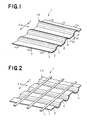
- Figs. 1 and 2 are perspective views of a female member 1, depicting its top and bottom sides 2, 3, respectively.
- the female member 1 comprises a shaped component 1A made of a fibrous layer of thermoplastic synthetic fibers and strips 7 made from a thermoplastic synthetic resin.
- the shaped component 1A presents a so-called corrugated structure or the like.
- a plurality of ridges 4 shaped from the bottom side 3 toward the top side 3 extend in a direction as indicated by a double-headed arrow X and the ridges 4 are arranged intermittently in a direction as indicated by a double-headed arrow Y being orthogonal to the direction X.
- Each pair of the adjacent ridges 4 are connected to each other by a flat portion 6.
- a plurality of the strips 7 extending in the direction Y are arranged intermittently in the direction X.
- the strips 7 extend substantially in parallel one to another and heat-sealed or bonded by means of a gluing agent or an adhesive agent such as hot melt adhesive to the bottom side 3 at the flat portions 6.
- a fibrous layer such as a nonwoven fabric of thermoplastic synthetic staple fibers or continuous filaments which are entangled or melt-bonded with each other to be engageable with the male (hook) member, more preferably of crimped conjugated fibers, having a fineness of 0.5 ⁇ 15 d and a basis weight of 10 ⁇ 100 g/m 2 may be employed as the fibrous layer as material for the shaped component 1A.
- Each of the ridges 6 may have a height of 1 ⁇ 10 mm, more preferably of 2 ⁇ 5 mm as measured from the flat portion 6 to a crest 8 thereof and a width of 2 ⁇ 10 mm, more preferably of 3 ⁇ 7 mm as measured in the direction Y.
- Each of the strips 7 as the other component of the female member 1 may have a width of 0.5 ⁇ 7 mm, more preferably of 1 ⁇ 5 mm and a thickness of 0.01 ⁇ 0.2 mm, more preferably of approximately 0.02 ⁇ 0.1 mm.
- Each pair of the adjacent strips 7 may be spaced from each other by 0.3 ⁇ 10 mm, more preferably by 0.5 ⁇ 5 mm.
- the strips 7 may be heat-sealed or bonded by means of a gluing agent or an adhesive agent such as hot melt adhesive to the bottom side of the shaped component 1A at the respective flat portions 6.
- the female member 1 may be attached to an article with the bottom side 3 thereof being stitched to the article or bonded to the article by means of a gluing agent or an adhesive agent at said flat portions 6. With the female member 1 attached to the article in this way, a male member of the mechanical fastener is to be releasably engaged.
- the male member can be most reliably engaged with the ridges 4 of the female member 1.
- the shaped component 1A is effectively prevented from being stretched in the direction Y by the strips 7 bonded thereto since the strips 7 are arranged so as to be intermittent in the direction X and continuous in the direction Y. Accordingly, the ridges 4 can maintain their initial heights.
- the shaped component 1A is relatively flexible in the direction X as well as in the direction Y without being significantly restricted by the strips 7.
- the member 1 can follow a deformation of the article such as clothes and therefore does not deteriorate feeling to wear such article.
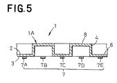
- Figs. 3, 4 and 5 illustrate a variant of the female member according to the invention, in which Figs. 3 and 4 are perspective views similar to Figs. 1 and 2, and Fig. 5 is a sectional view taken along a line V-V in Fig. 3.
- the ridges 4 are arranged intermittently in the direction X as well as in the direction Y.
- Each of the ridges 4 has a length L of 2 mm or larger and each pair of the adjacent ridges 4 are spaced from each other by distances D 1 , D 2 of 0 ⁇ 10 mm, more preferably of 2 ⁇ 7 mm.
- Each of the ridges 4 has a width W of 2 ⁇ 10 mm, more preferably of 3 ⁇ 7 mm.
- the strips 7 are dimensioned in the same manner as in the case illustrated by Fig. 2 and each of the strips 7 is assigned to each row along which the ridges 4 and the flat portions 6 are alternately arranged in the direction Y.
- the strips 7 assigned to the respective rows are designated by 7A, 7B, ..., 7E. It should be understood that some of the strips 7A ⁇ 7E, for example, the strips 7B and 7D may be eliminated without departing from the spirit and the effect of the invention.
- the remaining strips 7A, 7C, 7E can sufficiently prevent the shaped component 1A from being stretched in the direction Y and thereby achieve the same effect as in the case of Fig. 1.
- the female member 1 may further facilitate the male member to be engaged with the female member 1 than in the case illustrated by Fig. 1 since the ridges 4 are arranged intermittently in the direction X as well as in the direction Y.
- the female member 1 according to the invention may be obtained, for example, by a method comprising the steps of thermo-embossing the nonwoven fabric of thermoplastic synthetic fibers to form the ridges 4 and the flat portions 6 and pressure-heat-sealing a plurality of the strips 7 discharged from an extruder against the bottom sides of the respective flat portions 6 before the strips 7 are hardened.
- the fibrous layer includes a plurality of the ridges arranged intermittently on its top side and a plurality of the thermoplastic synthetic resin strips intermittently bonded to the bottom side of the fibrous layer so as to be spaced one from another and to extend in parallel one to another.
- the ridges facilitate the male member to be engaged with the female member and the arrangement of the strips are effective to prevent the ridges from being deformed due to stretch of the shaped fibrous layer as well as from losing its initial flexibility.
- the female member as one component of the mechanical fastener is relatively flexible and, when it is used with clothes, well follows deformation thereof without creating a feeling of discomfort against a wearer.
Abstract
Description
- This invention relates to a female member of a mechanical fastener consisting a pair of male and female members adapted to be releasably engaged with each other.
- Japanese Patent Application Disclosure Gazette (Kokai) No. Hei2-18036 discloses an example of such a female member, in which a fibrous layer having a fineness of 1 ∼ 10 d and a basis weight of 5 ∼ 200 g/m2 is laminated on a plastic film having a thickness of approximately 0.025 ∼ 0.13 mm and in which the fibrous layer form a corrugated structure. In this corrugated structure, regions of the fibrous layer projecting from the plastic film engageably receive a male member (referred to also as a hook member) of the mechanical fastener.
- When an article to which the mechanical fastener is attached includes clothes and other garments such as diapers, it is often desired that at least one of the female and male members is as soft as possible to avoid a problem that this member might irritate a wearer's skin. Sometimes, it is also desired for this member to have a sufficiently low rigidity to allow clothes or the like to which this member is attached to be easily deformed. Such requirement should be met particularly when the mechanical fastener is employed in disposable diapers for babies. However, with the conventional female member as described above, the fibrous layer forming the corrugated structure might lose its initial softness and become rigid due to the presence of the plastic film.
- In view of the above problem, it is a an object of the invention to improve a softness of the conventional mechanical fastener consisting of a plastic film and a fibrous layer.
- According to the invention, there is provided a female member of a mechanical fastener consisting of a pair of male and female members adapted to be releasably engaged with each other, wherein: a region of the female member for engagement with the male member is formed by a fibrous layer of thermoplastic synthetic fibers and has top and bottom sides; and a plurality of thermoplastic synthetic resin strips are bonded to the bottom side of the fibrous layer so as to extend in parallel one to another in one direction and a plurality of ridges are shaped from the bottom side toward the top side of the fibrous layer intermittently in the one direction so that the bottom side of the fibrous layer is spaced toward the top side of the fibrous layer from the strips.
- According to one of preferred embodiments of the invention, the ridges are arranged intermittently also in a direction orthogonal to the one direction.
- According to another embodiment of the invention, the ridges extend continuously in a direction orthogonal to the one direction.
- According to still another embodiment of the invention, the fibrous layer is made of crimped conjugated fibers.
- According to further another embodiment of the invention, the fibrous layer presents a corrugated structure having the strips bonded to the bottom thereof side along respective trough-like portions thereof.
- According to still further another embodiment of the invention, the fibrous layer is made of a nonwoven fabric.
- Fig. 1 is a perspective view depicting an embodiment of female member according to the invention as a component of a mechanical fastener as viewed from above;
- Fig. 2 is a perspective view depicting the female member depicted by Fig. 1 as viewed from below;
- Fig. 3 is a view similar to Fig. 1 depicting a variant of the female member depicted by Fig. 1;
- Fig. 4 is a perspective view depicting the variant shown by Fig. 3 as viewed from below; and
- Fig. 5 is a sectional view taken along a line V-V in Fig. 3.
-
- Details of a female member according to the invention as a component of a mechanical fastener will be more fully understood from the description given hereunder with reference to the accompanying drawings.
- Figs. 1 and 2 are perspective views of a
female member 1, depicting its top andbottom sides female member 1 comprises ashaped component 1A made of a fibrous layer of thermoplastic synthetic fibers andstrips 7 made from a thermoplastic synthetic resin. Theshaped component 1A presents a so-called corrugated structure or the like. A plurality ofridges 4 shaped from thebottom side 3 toward thetop side 3 extend in a direction as indicated by a double-headed arrow X and theridges 4 are arranged intermittently in a direction as indicated by a double-headed arrow Y being orthogonal to the direction X. Each pair of theadjacent ridges 4 are connected to each other by aflat portion 6. On thebottom side 3, a plurality of thestrips 7 extending in the direction Y are arranged intermittently in the direction X. Thestrips 7 extend substantially in parallel one to another and heat-sealed or bonded by means of a gluing agent or an adhesive agent such as hot melt adhesive to thebottom side 3 at theflat portions 6. - To obtain the
female member 1 of such a configuration, a fibrous layer such as a nonwoven fabric of thermoplastic synthetic staple fibers or continuous filaments which are entangled or melt-bonded with each other to be engageable with the male (hook) member, more preferably of crimped conjugated fibers, having a fineness of 0.5 ∼ 15 d and a basis weight of 10 ∼ 100 g/m2 may be employed as the fibrous layer as material for theshaped component 1A. Each of theridges 6 may have a height of 1 ∼ 10 mm, more preferably of 2 ∼ 5 mm as measured from theflat portion 6 to acrest 8 thereof and a width of 2 ∼ 10 mm, more preferably of 3 ∼ 7 mm as measured in the direction Y. - Each of the
strips 7 as the other component of thefemale member 1 may have a width of 0.5 ∼ 7 mm, more preferably of 1 ∼ 5 mm and a thickness of 0.01 ∼ 0.2 mm, more preferably of approximately 0.02 ∼ 0.1 mm. Each pair of theadjacent strips 7 may be spaced from each other by 0.3 ∼ 10 mm, more preferably by 0.5 ∼ 5 mm. Thestrips 7 may be heat-sealed or bonded by means of a gluing agent or an adhesive agent such as hot melt adhesive to the bottom side of theshaped component 1A at the respectiveflat portions 6. - The
female member 1 may be attached to an article with thebottom side 3 thereof being stitched to the article or bonded to the article by means of a gluing agent or an adhesive agent at saidflat portions 6. With thefemale member 1 attached to the article in this way, a male member of the mechanical fastener is to be releasably engaged. The male member can be most reliably engaged with theridges 4 of thefemale member 1. Theshaped component 1A is effectively prevented from being stretched in the direction Y by thestrips 7 bonded thereto since thestrips 7 are arranged so as to be intermittent in the direction X and continuous in the direction Y. Accordingly, theridges 4 can maintain their initial heights. On the other hand, theshaped component 1A is relatively flexible in the direction X as well as in the direction Y without being significantly restricted by thestrips 7. In other words, themember 1 can follow a deformation of the article such as clothes and therefore does not deteriorate feeling to wear such article. - Figs. 3, 4 and 5 illustrate a variant of the female member according to the invention, in which Figs. 3 and 4 are perspective views similar to Figs. 1 and 2, and Fig. 5 is a sectional view taken along a line V-V in Fig. 3. According to this embodiment of the
female member 1, theridges 4 are arranged intermittently in the direction X as well as in the direction Y. Each of theridges 4 has a length L of 2 mm or larger and each pair of theadjacent ridges 4 are spaced from each other by distances D1, D2 of 0 ∼ 10 mm, more preferably of 2 ∼ 7 mm. Each of theridges 4 has a width W of 2 ∼ 10 mm, more preferably of 3 ∼ 7 mm. Thestrips 7 are dimensioned in the same manner as in the case illustrated by Fig. 2 and each of thestrips 7 is assigned to each row along which theridges 4 and theflat portions 6 are alternately arranged in the direction Y. Thestrips 7 assigned to the respective rows are designated by 7A, 7B, ..., 7E. It should be understood that some of thestrips 7A ∼ 7E, for example, thestrips remaining strips shaped component 1A from being stretched in the direction Y and thereby achieve the same effect as in the case of Fig. 1. Thefemale member 1 according to this embodiment may further facilitate the male member to be engaged with thefemale member 1 than in the case illustrated by Fig. 1 since theridges 4 are arranged intermittently in the direction X as well as in the direction Y. - The
female member 1 according to the invention may be obtained, for example, by a method comprising the steps of thermo-embossing the nonwoven fabric of thermoplastic synthetic fibers to form theridges 4 and theflat portions 6 and pressure-heat-sealing a plurality of thestrips 7 discharged from an extruder against the bottom sides of the respectiveflat portions 6 before thestrips 7 are hardened. - According to the important feature of the invention, the fibrous layer includes a plurality of the ridges arranged intermittently on its top side and a plurality of the thermoplastic synthetic resin strips intermittently bonded to the bottom side of the fibrous layer so as to be spaced one from another and to extend in parallel one to another. The ridges facilitate the male member to be engaged with the female member and the arrangement of the strips are effective to prevent the ridges from being deformed due to stretch of the shaped fibrous layer as well as from losing its initial flexibility. In this manner, the female member as one component of the mechanical fastener is relatively flexible and, when it is used with clothes, well follows deformation thereof without creating a feeling of discomfort against a wearer.
Claims (6)
- A female member of a mechanical fastener consisting of a pair of male and female members adapted to be releasably engaged with each other, wherein:
said female member for engagement with said male member is formed by a fibrous layer of thermoplastic synthetic fibers and has top and bottom sides; a plurality of thermoplastic synthetic resin strips are bonded to said bottom side of said the fibrous layer so as to extend in parallel one to another in one direction; and a plurality of ridges are shaped from said bottom side toward said top side of said fibrous layer intermittently in said one direction so that said bottom side of said fibrous layer is spaced toward said top side of said fibrous layer from said strips. - A female member according to Claim 1, wherein said ridges are arranged intermittently also in a direction orthogonal to said one direction.
- A female member according to Claim 1, wherein said ridges extend continuously in a direction orthogonal to said one direction.
- A female member according to Claim 1, wherein said fibrous layer is made of crimped conjugated fiber.
- A female member according to Claim 1 and 4, wherein said fibrous layer presents a corrugated structure having said strips bonded to a bottom side thereof along respective trough-like portions thereof.
- A female member according to Claim 1, wherein said fibrous layer is made of a nonwoven fabric.
Applications Claiming Priority (3)
| Application Number | Priority Date | Filing Date | Title |
|---|---|---|---|
| JP30085897 | 1997-10-31 | ||
| JP30085897A JP3532081B2 (en) | 1997-10-31 | 1997-10-31 | Female parts of mechanical fasteners |
| JP300858/97 | 1997-10-31 |
Publications (3)
| Publication Number | Publication Date |
|---|---|
| EP0913104A2 true EP0913104A2 (en) | 1999-05-06 |
| EP0913104A3 EP0913104A3 (en) | 1999-09-29 |
| EP0913104B1 EP0913104B1 (en) | 2003-03-12 |
Family
ID=17889975
Family Applications (1)
| Application Number | Title | Priority Date | Filing Date |
|---|---|---|---|
| EP98308837A Expired - Lifetime EP0913104B1 (en) | 1997-10-31 | 1998-10-28 | Female member of mechanical fastener |
Country Status (13)
| Country | Link |
|---|---|
| US (1) | US6146738A (en) |
| EP (1) | EP0913104B1 (en) |
| JP (1) | JP3532081B2 (en) |
| KR (1) | KR100478761B1 (en) |
| CN (1) | CN1126482C (en) |
| AU (1) | AU736729B2 (en) |
| BR (1) | BR9805098A (en) |
| CA (1) | CA2252319C (en) |
| DE (1) | DE69812032T2 (en) |
| ID (1) | ID21198A (en) |
| MY (1) | MY119739A (en) |
| SG (1) | SG72881A1 (en) |
| TW (1) | TW497961B (en) |
Cited By (1)
| Publication number | Priority date | Publication date | Assignee | Title |
|---|---|---|---|---|
| US7805818B2 (en) | 2001-09-05 | 2010-10-05 | The Procter & Gamble Company | Nonwoven loop member for a mechanical fastener |
Families Citing this family (20)
| Publication number | Priority date | Publication date | Assignee | Title |
|---|---|---|---|---|
| JP3532081B2 (en) * | 1997-10-31 | 2004-05-31 | ユニ・チャーム株式会社 | Female parts of mechanical fasteners |
| US6849067B2 (en) | 1999-11-22 | 2005-02-01 | Kimberly-Clark Worldwide, Inc. | Absorbent articles with refastenable side seams |
| US6645190B1 (en) | 1999-11-22 | 2003-11-11 | Kimberly-Clark Worldwide, Inc. | Absorbent article with non-irritating refastenable seams |
| US8343127B1 (en) | 1999-11-22 | 2013-01-01 | Kimberly-Clark Worldwide, Inc. | Absorbent articles with garment-like refastenable seams |
| US6764475B1 (en) | 1998-12-18 | 2004-07-20 | Kimberly-Clark Worldwide, Inc. | Absorbent articles having differential strength refastenable seam |
| US6554816B1 (en) | 1999-11-22 | 2003-04-29 | Kimberly-Clarke Worldwide, Inc. | Absorbent articles with shaped fastening component |
| US6447497B1 (en) * | 1999-11-22 | 2002-09-10 | Kimberly-Clark Worldwide, Inc. | Absorbent article with child resistant refastenable seams |
| US6761711B1 (en) | 1998-12-18 | 2004-07-13 | Kimberly-Clark Worldwide, Inc. | Absorbent articles with refastenable side seams |
| AR021908A1 (en) | 1998-12-18 | 2002-09-04 | Kimberly Clark Co | AN ABSORBENT ARTICLE WITH CLAMPED FASTENERS AND A METHOD TO CONFIRM THE SAME. |
| US6953452B2 (en) * | 2001-12-31 | 2005-10-11 | Kimberly-Clark Worldwide, Inc. | Mechanical fastening system for an absorbent article |
| US20030125705A1 (en) | 2001-12-31 | 2003-07-03 | Kimberly-Clark Worldwide, Inc. | Absorbent article with improved fastening system and method of fastening thereof |
| US8007485B2 (en) | 2001-12-31 | 2011-08-30 | Kimberly-Clark Worldwide, Inc. | Mechanical fastening system for an absorbent article |
| US20030125707A1 (en) * | 2001-12-31 | 2003-07-03 | Kimberly-Clark Worldwide, Inc. | Mechanical fastening system for an absorbent article |
| US6969377B2 (en) | 2001-12-31 | 2005-11-29 | Kimberly-Clark Worldwide, Inc. | Mechanical fastening system for an absorbent article |
| US8323435B2 (en) | 2002-07-31 | 2012-12-04 | Kimberly-Clark Worldwide, Inc. | Mechanical fastening system for an article |
| US7637898B2 (en) * | 2002-08-16 | 2009-12-29 | Kimberly-Clark Wordwide, Inc. | Disposable absorbent pant having refastenable seams |
| US7052565B2 (en) * | 2003-01-27 | 2006-05-30 | 3M Innovative Properties Company | Web constructions with severed elongate strands |
| US20060080810A1 (en) * | 2004-10-18 | 2006-04-20 | Horn Thomas A | Bonding patterns for construction of a knitted fabric landing zone |
| FR2952791B1 (en) * | 2009-11-20 | 2012-01-06 | Aplix Sa | FEMALE THERMOTRACTION FILM BUCKLE AND FILM ELEMENT |
| CA2954712C (en) | 2010-07-16 | 2020-06-30 | Gerald Rocha | Dimensionally flexible touch fastener strip |
Citations (2)
| Publication number | Priority date | Publication date | Assignee | Title |
|---|---|---|---|---|
| EP0341993B1 (en) * | 1988-05-13 | 1993-08-18 | Minnesota Mining And Manufacturing Company | Sheet material for forming the loop portion for hook and loop fasteners |
| US5380313A (en) * | 1987-06-19 | 1995-01-10 | The Proctor & Gamble Company | Loop fastening material for fastening device and method of making same |
Family Cites Families (5)
| Publication number | Priority date | Publication date | Assignee | Title |
|---|---|---|---|---|
| US2627644A (en) * | 1950-06-24 | 1953-02-10 | Us Rubber Co | Single-ply corrugated fabric and method of making the same |
| US5032122A (en) | 1987-04-24 | 1991-07-16 | The Procter & Gamble Company | Loop fastening material for fastening device and method of making same |
| US5256231A (en) * | 1988-05-13 | 1993-10-26 | Minnesota Mining And Manufacturing Company | Method for making a sheet of loop material |
| JP3131559B2 (en) * | 1995-12-07 | 2001-02-05 | 大和紡績株式会社 | Bulk nonwoven fabric, method for producing the same, and female fastener material |
| JP3532081B2 (en) * | 1997-10-31 | 2004-05-31 | ユニ・チャーム株式会社 | Female parts of mechanical fasteners |
-
1997
- 1997-10-31 JP JP30085897A patent/JP3532081B2/en not_active Expired - Fee Related
-
1998
- 1998-10-26 SG SG1998004274A patent/SG72881A1/en unknown
- 1998-10-27 ID IDP981411A patent/ID21198A/en unknown
- 1998-10-28 TW TW087117859A patent/TW497961B/en not_active IP Right Cessation
- 1998-10-28 AU AU89562/98A patent/AU736729B2/en not_active Ceased
- 1998-10-28 DE DE69812032T patent/DE69812032T2/en not_active Expired - Lifetime
- 1998-10-28 MY MYPI98004908A patent/MY119739A/en unknown
- 1998-10-28 EP EP98308837A patent/EP0913104B1/en not_active Expired - Lifetime
- 1998-10-30 CN CN98123499A patent/CN1126482C/en not_active Expired - Fee Related
- 1998-10-30 US US09/183,512 patent/US6146738A/en not_active Expired - Lifetime
- 1998-10-30 KR KR10-1998-0046060A patent/KR100478761B1/en not_active IP Right Cessation
- 1998-10-30 CA CA002252319A patent/CA2252319C/en not_active Expired - Fee Related
- 1998-10-30 BR BR9805098-2A patent/BR9805098A/en not_active IP Right Cessation
Patent Citations (2)
| Publication number | Priority date | Publication date | Assignee | Title |
|---|---|---|---|---|
| US5380313A (en) * | 1987-06-19 | 1995-01-10 | The Proctor & Gamble Company | Loop fastening material for fastening device and method of making same |
| EP0341993B1 (en) * | 1988-05-13 | 1993-08-18 | Minnesota Mining And Manufacturing Company | Sheet material for forming the loop portion for hook and loop fasteners |
Cited By (4)
| Publication number | Priority date | Publication date | Assignee | Title |
|---|---|---|---|---|
| US7805818B2 (en) | 2001-09-05 | 2010-10-05 | The Procter & Gamble Company | Nonwoven loop member for a mechanical fastener |
| USD640064S1 (en) | 2002-09-05 | 2011-06-21 | The Procter & Gamble Company | Nonwoven material with pattern element |
| USD642809S1 (en) | 2002-09-05 | 2011-08-09 | The Procter & Gamble Company | Nonwoven material with pattern element |
| US9259059B2 (en) | 2002-09-05 | 2016-02-16 | The Procter & Gamble Company | Nonwoven loop member for a mechanical fastener |
Also Published As
| Publication number | Publication date |
|---|---|
| MY119739A (en) | 2005-07-29 |
| CN1126482C (en) | 2003-11-05 |
| BR9805098A (en) | 1999-11-09 |
| CN1216693A (en) | 1999-05-19 |
| DE69812032D1 (en) | 2003-04-17 |
| JPH11127916A (en) | 1999-05-18 |
| US6146738A (en) | 2000-11-14 |
| KR100478761B1 (en) | 2005-07-25 |
| AU8956298A (en) | 1999-05-20 |
| KR19990037513A (en) | 1999-05-25 |
| EP0913104A3 (en) | 1999-09-29 |
| EP0913104B1 (en) | 2003-03-12 |
| JP3532081B2 (en) | 2004-05-31 |
| AU736729B2 (en) | 2001-08-02 |
| TW497961B (en) | 2002-08-11 |
| DE69812032T2 (en) | 2003-12-18 |
| CA2252319A1 (en) | 1999-04-30 |
| ID21198A (en) | 1999-05-06 |
| SG72881A1 (en) | 2000-05-23 |
| CA2252319C (en) | 2002-02-05 |
Similar Documents
| Publication | Publication Date | Title |
|---|---|---|
| EP0913104B1 (en) | Female member of mechanical fastener | |
| US6332250B1 (en) | Mechanical fastener | |
| KR100452238B1 (en) | Liquid-permeable topsheet for body exudates absorbent article, apparatus and method for manufacturing same | |
| EP1065046B1 (en) | Elastically stretchable sheet | |
| WO2011030550A1 (en) | Absorbent article using hook-and-loop fastener | |
| KR100593657B1 (en) | Pants-type disposable wear | |
| US20020035747A1 (en) | Briefs for supporting an absorbent article | |
| KR100706043B1 (en) | Flexible complex sheet for use in a disposable wearing article | |
| EP1559822A1 (en) | Nonwoven fabric and method for production thereof | |
| CN1520265A (en) | Bi-stable fastening | |
| CA2011596A1 (en) | Disposable diaper with refastenable mechanical fastening system | |
| EP1066961A1 (en) | Process for making elastically stretchable composite sheet | |
| KR20040029397A (en) | Secondary attachment system for personal care article | |
| EP1062927B1 (en) | Liquid-pervious topsheet for disposable absorbent article and process for making the same | |
| US20100174258A1 (en) | Absorptive article | |
| TW537974B (en) | Elastic stretchable laminate sheet and it production method | |
| KR100681288B1 (en) | Disposable wearing article | |
| EP1184014A2 (en) | Process for manufacturing elastically strechable and contractible composite sheet | |
| US20200000062A1 (en) | Band-like body | |
| RU2700955C1 (en) | Absorbent product | |
| JP6823971B2 (en) | Band | |
| JP2003164488A (en) | Sanitary briefs | |
| JP3098436B2 (en) | Velcro fastener female material | |
| WO2002024136A1 (en) | Brief for supporting an absorbent article comprising fastening members |
Legal Events
| Date | Code | Title | Description |
|---|---|---|---|
| PUAI | Public reference made under article 153(3) epc to a published international application that has entered the european phase |
Free format text: ORIGINAL CODE: 0009012 |
|
| AK | Designated contracting states |
Kind code of ref document: A2 Designated state(s): DE FR GB NL SE |
|
| AX | Request for extension of the european patent |
Free format text: AL;LT;LV;MK;RO;SI |
|
| PUAL | Search report despatched |
Free format text: ORIGINAL CODE: 0009013 |
|
| AK | Designated contracting states |
Kind code of ref document: A3 Designated state(s): AT BE CH CY DE DK ES FI FR GB GR IE IT LI LU MC NL PT SE |
|
| AX | Request for extension of the european patent |
Free format text: AL;LT;LV;MK;RO;SI |
|
| 17P | Request for examination filed |
Effective date: 20000226 |
|
| AKX | Designation fees paid |
Free format text: DE FR GB NL SE |
|
| 17Q | First examination report despatched |
Effective date: 20011205 |
|
| GRAG | Despatch of communication of intention to grant |
Free format text: ORIGINAL CODE: EPIDOS AGRA |
|
| GRAG | Despatch of communication of intention to grant |
Free format text: ORIGINAL CODE: EPIDOS AGRA |
|
| GRAH | Despatch of communication of intention to grant a patent |
Free format text: ORIGINAL CODE: EPIDOS IGRA |
|
| GRAH | Despatch of communication of intention to grant a patent |
Free format text: ORIGINAL CODE: EPIDOS IGRA |
|
| GRAA | (expected) grant |
Free format text: ORIGINAL CODE: 0009210 |
|
| AK | Designated contracting states |
Designated state(s): DE FR GB NL SE |
|
| REG | Reference to a national code |
Ref country code: GB Ref legal event code: FG4D |
|
| REF | Corresponds to: |
Ref document number: 69812032 Country of ref document: DE Date of ref document: 20030417 Kind code of ref document: P |
|
| REG | Reference to a national code |
Ref country code: SE Ref legal event code: TRGR |
|
| ET | Fr: translation filed | ||
| PLBE | No opposition filed within time limit |
Free format text: ORIGINAL CODE: 0009261 |
|
| STAA | Information on the status of an ep patent application or granted ep patent |
Free format text: STATUS: NO OPPOSITION FILED WITHIN TIME LIMIT |
|
| 26N | No opposition filed |
Effective date: 20031215 |
|
| PGFP | Annual fee paid to national office [announced via postgrant information from national office to epo] |
Ref country code: FR Payment date: 20121018 Year of fee payment: 15 Ref country code: DE Payment date: 20121024 Year of fee payment: 15 |
|
| PGFP | Annual fee paid to national office [announced via postgrant information from national office to epo] |
Ref country code: SE Payment date: 20121011 Year of fee payment: 15 Ref country code: GB Payment date: 20121024 Year of fee payment: 15 |
|
| PGFP | Annual fee paid to national office [announced via postgrant information from national office to epo] |
Ref country code: NL Payment date: 20121016 Year of fee payment: 15 |
|
| REG | Reference to a national code |
Ref country code: NL Ref legal event code: V1 Effective date: 20140501 |
|
| REG | Reference to a national code |
Ref country code: SE Ref legal event code: EUG |
|
| GBPC | Gb: european patent ceased through non-payment of renewal fee |
Effective date: 20131028 |
|
| PG25 | Lapsed in a contracting state [announced via postgrant information from national office to epo] |
Ref country code: GB Free format text: LAPSE BECAUSE OF NON-PAYMENT OF DUE FEES Effective date: 20131028 |
|
| REG | Reference to a national code |
Ref country code: FR Ref legal event code: ST Effective date: 20140630 |
|
| REG | Reference to a national code |
Ref country code: DE Ref legal event code: R119 Ref document number: 69812032 Country of ref document: DE Effective date: 20140501 |
|
| PG25 | Lapsed in a contracting state [announced via postgrant information from national office to epo] |
Ref country code: FR Free format text: LAPSE BECAUSE OF NON-PAYMENT OF DUE FEES Effective date: 20131031 Ref country code: DE Free format text: LAPSE BECAUSE OF NON-PAYMENT OF DUE FEES Effective date: 20140501 Ref country code: SE Free format text: LAPSE BECAUSE OF NON-PAYMENT OF DUE FEES Effective date: 20131029 Ref country code: NL Free format text: LAPSE BECAUSE OF NON-PAYMENT OF DUE FEES Effective date: 20140501 |