EP0911754A2 - Intelligent touch sensitive tablet display - Google Patents
Intelligent touch sensitive tablet display Download PDFInfo
- Publication number
- EP0911754A2 EP0911754A2 EP98306672A EP98306672A EP0911754A2 EP 0911754 A2 EP0911754 A2 EP 0911754A2 EP 98306672 A EP98306672 A EP 98306672A EP 98306672 A EP98306672 A EP 98306672A EP 0911754 A2 EP0911754 A2 EP 0911754A2
- Authority
- EP
- European Patent Office
- Prior art keywords
- stylus
- display
- touch
- parcel
- tablet display
- Prior art date
- Legal status (The legal status is an assumption and is not a legal conclusion. Google has not performed a legal analysis and makes no representation as to the accuracy of the status listed.)
- Withdrawn
Links
Images


Classifications
-
- G—PHYSICS
- G07—CHECKING-DEVICES
- G07B—TICKET-ISSUING APPARATUS; FARE-REGISTERING APPARATUS; FRANKING APPARATUS
- G07B17/00—Franking apparatus
- G07B17/00459—Details relating to mailpieces in a franking system
- G07B17/00661—Sensing or measuring mailpieces
-
- G—PHYSICS
- G06—COMPUTING; CALCULATING OR COUNTING
- G06F—ELECTRIC DIGITAL DATA PROCESSING
- G06F3/00—Input arrangements for transferring data to be processed into a form capable of being handled by the computer; Output arrangements for transferring data from processing unit to output unit, e.g. interface arrangements
- G06F3/01—Input arrangements or combined input and output arrangements for interaction between user and computer
- G06F3/048—Interaction techniques based on graphical user interfaces [GUI]
- G06F3/0487—Interaction techniques based on graphical user interfaces [GUI] using specific features provided by the input device, e.g. functions controlled by the rotation of a mouse with dual sensing arrangements, or of the nature of the input device, e.g. tap gestures based on pressure sensed by a digitiser
- G06F3/0488—Interaction techniques based on graphical user interfaces [GUI] using specific features provided by the input device, e.g. functions controlled by the rotation of a mouse with dual sensing arrangements, or of the nature of the input device, e.g. tap gestures based on pressure sensed by a digitiser using a touch-screen or digitiser, e.g. input of commands through traced gestures
-
- G—PHYSICS
- G06—COMPUTING; CALCULATING OR COUNTING
- G06K—GRAPHICAL DATA READING; PRESENTATION OF DATA; RECORD CARRIERS; HANDLING RECORD CARRIERS
- G06K17/00—Methods or arrangements for effecting co-operative working between equipments covered by two or more of main groups G06K1/00 - G06K15/00, e.g. automatic card files incorporating conveying and reading operations
-
- G—PHYSICS
- G06—COMPUTING; CALCULATING OR COUNTING
- G06Q—INFORMATION AND COMMUNICATION TECHNOLOGY [ICT] SPECIALLY ADAPTED FOR ADMINISTRATIVE, COMMERCIAL, FINANCIAL, MANAGERIAL OR SUPERVISORY PURPOSES; SYSTEMS OR METHODS SPECIALLY ADAPTED FOR ADMINISTRATIVE, COMMERCIAL, FINANCIAL, MANAGERIAL OR SUPERVISORY PURPOSES, NOT OTHERWISE PROVIDED FOR
- G06Q10/00—Administration; Management
- G06Q10/08—Logistics, e.g. warehousing, loading or distribution; Inventory or stock management
-
- G—PHYSICS
- G07—CHECKING-DEVICES
- G07B—TICKET-ISSUING APPARATUS; FARE-REGISTERING APPARATUS; FRANKING APPARATUS
- G07B17/00—Franking apparatus
- G07B17/00016—Relations between apparatus, e.g. franking machine at customer or apparatus at post office, in a franking system
- G07B17/0008—Communication details outside or between apparatus
-
- G—PHYSICS
- G07—CHECKING-DEVICES
- G07B—TICKET-ISSUING APPARATUS; FARE-REGISTERING APPARATUS; FRANKING APPARATUS
- G07B17/00—Franking apparatus
- G07B17/00185—Details internally of apparatus in a franking system, e.g. franking machine at customer or apparatus at post office
- G07B17/00193—Constructional details of apparatus in a franking system
-
- G—PHYSICS
- G07—CHECKING-DEVICES
- G07B—TICKET-ISSUING APPARATUS; FARE-REGISTERING APPARATUS; FRANKING APPARATUS
- G07B17/00—Franking apparatus
- G07B17/00185—Details internally of apparatus in a franking system, e.g. franking machine at customer or apparatus at post office
- G07B17/00362—Calculation or computing within apparatus, e.g. calculation of postage value
-
- G—PHYSICS
- G07—CHECKING-DEVICES
- G07B—TICKET-ISSUING APPARATUS; FARE-REGISTERING APPARATUS; FRANKING APPARATUS
- G07B17/00—Franking apparatus
- G07B17/00459—Details relating to mailpieces in a franking system
- G07B17/00508—Printing or attaching on mailpieces
-
- G—PHYSICS
- G07—CHECKING-DEVICES
- G07B—TICKET-ISSUING APPARATUS; FARE-REGISTERING APPARATUS; FRANKING APPARATUS
- G07B17/00—Franking apparatus
- G07B17/00016—Relations between apparatus, e.g. franking machine at customer or apparatus at post office, in a franking system
- G07B17/0008—Communication details outside or between apparatus
- G07B2017/00088—Communication details outside or between apparatus via landlines
- G07B2017/00096—Communication details outside or between apparatus via landlines via phone lines
-
- G—PHYSICS
- G07—CHECKING-DEVICES
- G07B—TICKET-ISSUING APPARATUS; FARE-REGISTERING APPARATUS; FRANKING APPARATUS
- G07B17/00—Franking apparatus
- G07B17/00016—Relations between apparatus, e.g. franking machine at customer or apparatus at post office, in a franking system
- G07B17/0008—Communication details outside or between apparatus
- G07B2017/00112—Wireless
- G07B2017/0012—Wireless in a mobile phone system
-
- G—PHYSICS
- G07—CHECKING-DEVICES
- G07B—TICKET-ISSUING APPARATUS; FARE-REGISTERING APPARATUS; FRANKING APPARATUS
- G07B17/00—Franking apparatus
- G07B17/00185—Details internally of apparatus in a franking system, e.g. franking machine at customer or apparatus at post office
- G07B17/00193—Constructional details of apparatus in a franking system
- G07B2017/00217—Portable franking apparatus, i.e. the whole franking apparatus, not parts alone
-
- G—PHYSICS
- G07—CHECKING-DEVICES
- G07B—TICKET-ISSUING APPARATUS; FARE-REGISTERING APPARATUS; FRANKING APPARATUS
- G07B17/00—Franking apparatus
- G07B17/00185—Details internally of apparatus in a franking system, e.g. franking machine at customer or apparatus at post office
- G07B17/00193—Constructional details of apparatus in a franking system
- G07B2017/00266—Man-machine interface on the apparatus
- G07B2017/00274—Mechanical, e.g. keyboard
- G07B2017/00282—Touch screen
-
- G—PHYSICS
- G07—CHECKING-DEVICES
- G07B—TICKET-ISSUING APPARATUS; FARE-REGISTERING APPARATUS; FRANKING APPARATUS
- G07B17/00—Franking apparatus
- G07B17/00185—Details internally of apparatus in a franking system, e.g. franking machine at customer or apparatus at post office
- G07B17/00362—Calculation or computing within apparatus, e.g. calculation of postage value
- G07B2017/00379—Calculation of different sending options for a mail piece
-
- G—PHYSICS
- G07—CHECKING-DEVICES
- G07B—TICKET-ISSUING APPARATUS; FARE-REGISTERING APPARATUS; FRANKING APPARATUS
- G07B17/00—Franking apparatus
- G07B17/00459—Details relating to mailpieces in a franking system
- G07B17/00508—Printing or attaching on mailpieces
- G07B2017/00572—Details of printed item
- G07B2017/0058—Printing of code
- G07B2017/00588—Barcode
-
- G—PHYSICS
- G07—CHECKING-DEVICES
- G07B—TICKET-ISSUING APPARATUS; FARE-REGISTERING APPARATUS; FRANKING APPARATUS
- G07B17/00—Franking apparatus
- G07B17/00459—Details relating to mailpieces in a franking system
- G07B17/00661—Sensing or measuring mailpieces
- G07B2017/00709—Scanning mailpieces
- G07B2017/00717—Reading barcodes
Definitions
- This invention is related to object tracking systems and is useful in particular, to paperless parcel delivery systems with computerized tracking of parcels and electronic signature capture and storage.
- third party parcel delivery firms have developed which provide delivery services on a global scale for millions of parcels daily. This requires the generation of large amounts of paperwork for tracking each parcel as it moves through the sender's organization, to each of the various components of the third party delivery firm, such as receiving station, sending location trucking department, freighter or aircraft shipping, receiving location trucking, and finally to the customer whose signature must be obtained, returned, and stored for proof of delivery.
- Parcel tracking has been addressed in some areas, particularly in the area of parcel identification, by the development of bar codes and bar code scanners that allow identification of goods by machine.
- Bar code scanners are old and well known in the art. This approach is used in inventory checking systems, retail sales terminals, etc. See, for example, GB-2-212-310.
- scanning systems provide an improved ability to identify appropriately marked goods, they do not address the problem of obtaining signature records to prove receipt of goods.
- the problems related to paper handling and storage remain, due to the requirement for signature records.
- the prior art has failed to provide for control of parcel delivery in a manner which is low in labor and storage costs, reduces the time required to update information in a central record keeping facility, and avoids problems caused by lost receipts. Further the prior art has failed to provide for problems related to the small size of hand held computers, such as when a stylus and hand both contact the input panel at the same time.
- Fig. 1 is a block diagram showing the major system components and their interfaces.
- Fig. 2 shows the external configuration of system components including the touch panel display, the scanner output window, and a separate stylus.
- Fig. 3 shows a second view of the external configuration of system components including the touch panel display and the host link.
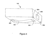
- Fig. 4 shows a third view of the external configuration of system components the host link and the holding strap on the bottom of the system.
- Fig. 5 shows the touch panel display with an alphanumeric keyboard on the display screen.
- Fig. 6 shows the touch panel display with a signature field and several command keypads displayed.
- Fig. 7 shows the internal arrangement of components within the parcel tracking system.
- Fig. 8 shows an exploded view of the stylus.
- Fig. 9 shows the docking station with an docked parcel tracking system.
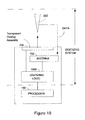
- Fig 10. shows a block diagram of the digitizing subsystem.
- FIGURE 1 a general overview of the major components used in the parcel tracking system 100 is shown.
- the system software which resides in storage 104 and Read Only Memory (ROM) 122 is used by the processor 102 to control the operation of the various devices.
- the system software includes both the software that resides in ROM 122 and the software that is in storage 104.
- the software includes BIOS, bar code algorithms, communication code, and power on self test (POST) diagnostics.
- BIOS Basic System on System
- BIOS Basic System on System
- BIOS Basic System on self test
- ROM 122 is the preferred location for this type of standard application because by their nature, this code will not vary with the application the system is put to. While code that does not need to be changed is appropriate for ROM 122, the code that is custom designed for a particular application or is likely to change from time to time is most appropriately stored in storage 104 since the contents of storage 104 are more easily updated.
- the parcel tracking system 100 does not require hard disk storage, floppy disks, PCMCIA cards, or other removable media to retain the code stored in storage 104.
- the requirement for disk storage is eliminated by using BIOS routines residing in ROM 122 to download the system software from the host system 118 with the host link 110 into storage 104. This eliminates the need for an expensive I/O subsystem and reduces the size and weight of the parcel tracking system 100.
- the object code is executed in the same manner as code loaded from disk storage in a typical prior art approach.
- the host link 110 uses infrared circuitry to transfer information into and out of the system. Infrared is used because it eliminates the problems associated with connectors, such as contact resistance, failures from bent or broken pins, alignment, etc.
- the infrared circuitry is connected to the internal serial port of the system.
- the infrared baud rate is programmable.
- the host link 110 utilizes a baud rate of 19.2 KB/SEC, and runs in the half duplex mode of operation, but those skilled in the art will recognize that these parameters can easily be changed to suit the needs of the particular operation.
- the types of software routines which would be downloaded from the host 118 via host link 110 would be device drivers such as the touch panel control software which would contain the screen formats for the particular user application, the bar code scanner code, stylus code, and the programming interfaces, etc.
- Examples of system code which would be downloaded would be code such as an operating system which would control the overall operation of the system.
- An example of a suitable operating system is the well known commercially available product sold by IBM Corporation, DOS 5.0.
- the host link 110 can be implemented in a variety of ways, including infrared link, cellular or radio transmission, conventional electrical contacts, or the like.
- infrared data link, cellular or radio are advantageous to avoid a data transfer mechanism which may be degraded by the presence of moisture (e.g., metal contacts).
- the host link 110 could use direct metal contacts (with care to ensure they are dry before use) for electrical data transfer.
- an internal modem could be used for data transmission to the host system 118.
- the host link 110 uses a docking station 902 (shown in FIGURE 9) which would function as a temporary host 118 or function as an infrared I/O device attached to a host such as a Personal computer, mainframe, etc..
- the parcel tracking system 100 could be docked in the docking station 902 after each parcel delivery for transfer of the parcel data to temporary storage while the user was enroute to the next delivery. After a suitable number of deliveries are made, or at the end of a predetermined period of time, whichever is most convenient, a batch transfer of multiple parcel data can be made from the docking station 902 to the host 118.
- the storage of multiple parcel data on conventional magnetic or optical storage devices for later input to the host system 118 can also be performed by the docking station 902.
- the docking station 902 can provide contacts for charging of a rechargeable battery in the parcel tracking system 100.
- portable docking stations 902 could be designed to accommodate a plurality of parcel tracking systems.
- the host link 110 can use a cellular modem, or radio in place of the infrared link.
- a cellular modem or radio allows direct transfer from the parcel tracking system 100 to the host system 118 without using the docking station 902.
- the touch panel display 108 (hereinafter the display) in the preferred embodiment is an LCD display panel or tablet display of the type well known in the art.
- the display 108 is equipped with a touch sensitive overlay (shown below in FIGURE 7) for capturing data entered either from a finger touch or from a stylus 202.
- the display 108 is sensitive to both stylus 202 and finger touch. This means the stylus 202 can draw on the display 108 or a finger can touch the display 108 to select options displayed in selected predetermined fields of the display 108.
- An advantage of the invention is the ability not only to detect the difference between finger touch and contact by the stylus 202 with the display 108, but also to detect when the stylus 202 is in close proximity to the display without actually being in contact with it.
- the stylus 202 takes precedence over touch. This allows the hand to rest on the display 108 while the other hand is drawing on the display 108 with the stylus 202.
- the bezel 206 (shown in FIGURE 2) which surrounds the display 108 incorporates a ring antenna 702 used in conjunction with the stylus 202 to measure the proximity of the stylus 202 to the display 108.
- the display 108 senses stylus 202 and turns the finger touch logic off. The finger touch logic remains off until the stylus 202 is removed from the vicinity of the display 108.
- the stylus 202 and ring antenna mechanism are discussed in more detail below, in relation to FIGURE 8.
- the processor 102 can format the display 108 such that a variety of fields having control information are presented.
- one field on the display 108 could be a command instructing the processor 102 to display an alphanumeric keyboard for entry of customer data such as the name of the person receiving the parcel.
- Another field could be a command instructing the processor to prepare a predetermined area of the screen to capture signature data entered by a stylus. Completion of the signature would be indicated to the system either by timeout after completion of data entry into the field or preferably by selecting a command displayed in a predetermined field of the display 108.
- the actual configuration of the control fields will vary depending on the requirements of the particular application and customer set. Those skilled in the art will recognize that while the screen format could be accomplished in a variety of ways, including hardware or programmable read only memories, the use of software stored in storage 104 and ROM 122 and executed by the processor 102 will typically be the most desirable method of display control.
- the bar code scanner 106 reads a bar code 120 affixed to a package (not shown) under control of the processor 102.
- Bar code laser scanners are well known in the art.
- the information read from the bar code 120 is stored in storage 104 under control of the processor 102.
- Activation of the scanning process can be accomplished in a variety of ways. For example, it can be automatically started when the customer information is entered into the touch panel display 108. It can automatically start when alphanumeric data is entered into the display 108. Additionally, a command field can be displayed at a predetermined location on the display 108 which would allow the user to activate the scanning process.
- the external host 118 can be any one of a number of commonly available processors, such as a mainframe, a minicomputer, a personal computer, or the like. The type and size of the host will be governed by the needs of the particular business using the parcel tracking system 100.
- FIGURES 2-4 show the physical configuration of the system. It will be understood by those skilled in the art that while the parcel tracking system 100 was drawn in the shape of a rectangular box for ease of illustration, the external packaging of the system would in practice be configured such that it would comfortably fit in the hand of a user (i.e., rounded edges, etc.).
- the top surface shows the touch panel display 108 surrounded by the bezel 206. and the side panel shows the bar code scanner window 204. Placement of the bar code scanner window 204 on the front end side of the parcel tracking system 100, as shown, allows the user to aim the bar code scanner 106 at a bar code 120 in a convenient manner.
- FIGURE 3 is a perspective view which shows the rear end side of the parcel tracking system 100 from that shown in FIGURE 2.
- the window 302 at this end of the parcel tacking system 100 allows the host link 110 to communicate with the host 118.
- Optional battery recharge contacts 304 are shown along the edge of the parcel tracking system 100.
- the preferred embodiment separates the bar code scanner 106 from the host link 110 to facilitate ease of packaging, resulting in the bar code scanner window 204 being located at the opposite end of the host link window 302.
- placement of the windows 204 and 302 or battery contacts 304 can be done in any manner deemed convenient.
- FIGURE 4 shows a bottom perspective view of the parcel tracking system 100.
- a strap 402 is attached to the bottom of the parcel tracking system 100 at ends 404 and 406.
- the strap 402 can be mechanically attached by any method deemed suitable.
- the function of the strap is to avoid accidental dropping of the parcel tracking system 100 and to provide a convenient way to hold the parcel tracking system 100 with one hand by allowing the user to slide one hand between the strap 402 and the parcel tracking system 100.
- FIGURE 5 shows the display 108 configured in the form of an alphanumeric keyboard.
- Each keypad 502 is displayed on display 108 at the most convenient location for the application in use.
- FIGURE 6 shows the display 108 configured with several keypads 502 at one side of the display and a large area defined as a signature entry field 602.
- the signature field 602 can be located at any location on the screen and the number of keypads 502 will vary with the particular application in use.
- FIGURE 7 shows the physical arrangement of the various major subassemblies in the preferred embodiment of the parcel tracking system 100.
- the top cover is comprised of bezel 206.
- the ring antenna assembly 702 which is used to sense the presence of the stylus 202 is fit within the bezel 206 in the preferred embodiment.
- a touch overlay assembly 704 is located such that it covers the opening in the bezel 206.
- the LCD display assembly 706 is located below the touch overlay assembly 704.
- Touch overlay assembly 704, LCD display assembly 706 and their associated circuitry comprise the touch panel display 108.
- the processor printed circuit board assembly 708, the touch detection circuitry and bar code scanner circuitry are located on scanner/touch panel assembly 710 for convenience, and the batteries are located on power board 712.
- FIGURE 8 shows an exploded view of the stylus 202.
- the stylus 202 is untethered and is an intelligent device.
- the stylus 202 consists of antennas 806 and 818 which are used to transmit and receive data, a stylus printed circuit board assembly 808 to process the data, and a battery 812 to provide power to the stylus 202.
- the casing for the stylus consists of a tip 802, a barrel sleeve 804 and a cap 816.
- an O-Ring 810 is used to seat the battery 812 against the stylus printed circuit board assembly 808, and a spring 814 is used to hold the battery 812 in pressure contact with its electrical connections.
- the cap 816, barrel sleeve 804 and tip 802 have threaded ends to facilitate replacement of the battery 812.
- Antenna 806 is mounted very close to the tip 802 of the stylus 202.
- Antenna 806 responds to information on the touch overlay assembly 704 of the touch panel display 108 and presents this information to the stylus printed circuit board assembly 808 for processing.
- the stylus printed circuit board 808 After the stylus printed circuit board 808 has processed the information, it sends the results to the antenna 818 via a voltage controlled oscillator (VCO) on the stylus printed circuit board assembly 808 for transmission back to the parcel tracking system 100.
- Antenna 818 is a ferrite core covered by winding. The information transmitted by antenna 818 is received by ring antenna assembly 702 mounted in the front bezel 206 and is then forwarded to the scanner/touch panel assembly 710.
- Stylus 202 also has a proximity detector that will determine that the stylus 202 is within a predetermined distance to the parcel tracking system 100, typically about two inches.
- the stylus 202 will transmit a code to the parcel tracking system 100 which will indicate that the stylus 202 is in proximity to the parcel tracking system 100 and that finger touch input should be turned off. This allows hand rejection when the stylus 202 is in use.
- the stylus 202 also has a "Touch Detect" capability which is programmable and allows the system to set the parameters that determine when the stylus 202 will "ink” the touch panel display 108. This is a very important feature in a system which captures hand written information.
- Touch sense exclusion works by disabling the touch sense function when the stylus 202 is detected to be within a predetermined distance from the touch overlay assembly 704.
- the touch overlay assembly 704 is alternately scanned for finger touch by performing a touch sense cycle, and stylus 202 presence by performing a stylus cycle.
- the digitizer program monitors the data generated by each cycle to determine which cycle to perform next.
- a stylus cycle is initiated when the ring antenna assembly 702 is driven with LOOPDRV at the same time the XYGA drives the touch overlay assembly 704 wires with TDCLK.
- LOOPDRV occurs one half of the 2XTDCLK cycle earlier than the rising edge of TDCLK.
- the stylus 202 tests for the presence of LOOPDRV at the coil around the ferrite core which receives the signal from the ring antenna assembly 702.
- the stylus 202 uses this signal to regenerate the a corresponding TDCLK signal.
- TDCLK is regenerated in the stylus 202 to synchronize the stylus 202 with the digitizer.
- the stylus 202 measures the signal on the touch overlay assembly 704 wires using a sensitive ball antenna at the stylus tip which is integrated during the TDCLK pulse durations. This value is digitized using an Analog to Digital converter in the stylus 202 and transmitted to the Digitizer as a serial data message. The data is converted to 400 KHz and 600 Khz signals The data is sent to the ring antenna assembly 702 of the digitizer by driving the stylus coil at the same time the digitizer switches the loop antenna to the input of an FSK (Frequency Shift Keying) receiver. Data is recovered by the quadrature detector circuit and read by the processor on the SDAT signal which is clock by SCLK. When the processor determines that the data is valid, the cycle is complete.
- FSK Frequency Shift Keying
- the stylus cycle When the stylus cycle is completed the stylus 202 is within range to be tested.
- the data received is compared to a programmable threshold value. If the data received exceeds the threshold value the touch cycles are no longer issued by the processor which issues another stylus cycle. The process is continued as long as the data received remains above the sum of the threshold value and a hysteresis value. During this time the sense cycles are suspended and the system is in the touch sense exclusion mode. The system resumes normal dual mode when the touch sense exclusion mode is ended.
- the docking station 902 is shown with a parcel tracking system 100 drawn in shadow form to illustrate the manner in which the parcel tracking system is placed in the docking station 902.
- the docking station 902 may be an intelligent terminal or may be an unintelligent I/O device attached to the host system 118 depending on the needs of the particular application.
- both the finger touch sense and stylus sense operate using the same fundamental principals. For this reason, it is possible to use the same basic system hardware to accomplish both tasks.
- the advantage of this approach is that the cost and size of the system is optimized compared to a system which uses two separate approaches to finger touch sense and stylus sense.
- Known systems which provide untethered stylus function require a wire grid to be located behind the display, which is usually a flat LCD. This approach causes the grid to be relatively far from the touch surface. It also requires the display to be flat and thin, or the grid would be too far from the touch surface to operate properly. If placed on the visible surface the wires would be visible.
- touch overlay assembly 702 is designed to provide a 2 axis grid which does not severely detract from the visibility of the display. It is installed over the display surface.
- the transparent overlay is made from layers of polyester film coated with thin lines of ITO connected electrically, via silver ink bus wires printed on the margins of the overlay, to the digitizing logic 1002. Installing the overlay on the display surface means that the touch system is not affected by display thickness or signal transparency.
- the stylus 202 position is detected by measuring the strength of a capacitively coupled signal from the transparent overlay 702.
- the ITO lines in the transparent overlay sequentially driven with a square wave signal.
- the signal induces a charge on a sensitive element on the stylus tip.
- the level of induced charge is proportional to the distance from the active line in the overlay. This value is measured and encoded by the stylus 202.
- the value measured in the stylus is used to determine the position of the stylus 202 in three axis. This method of measurement is made possible by the unique geometry of the transparent overlay and the stylus tip, which brings the two in close proximity when the stylus tip is on the overlay surface.
- the digitizer circuits drive a square wave signal on each of the overlay bus wires sequentially.
- the bus wires are connected to the ITO lines in the overlay in a predetermined pattern.
- the stylus measurements are mapped to the ITO lines in the transparent overlay which were active at the time the stylus measurement was taken. By comparing the relative signal levels represented in the measurements, to the position of the ITO lines in the overlay, the position of the stylus 202 is determined.
- the absolute signal strength represented by the stylus measurements is compared to a programmable threshold value.
- the value is adjusted to represent the absolute value which, when adjusted for lateral distance from the ITO line, represents the expected value of the measurement when the stylus tip is on or near the touch overlay assembly 704 surface. When the value exceeds the adjusted threshold limit the contact position is determined.
- the communications must be low power to be practical in a small battery powered device, wireless to be used with an untethered stylus, and low cost.
- the subject system uses a loop antenna located around the perimeter of the active digitizer area.
- the stylus contains a coil around a ferrite core located just behind the tip. Both of these devices are connected to a driver or a receiver circuit via analog switching devices, providing transmit and receive capability in both devices.
- a driver in the parcel delivery business will typically pick up the parcel tracking system 100 from a stationary docking station 902 before the driver begins the days work of picking up and delivering parcels.
- the device will typically have the following information in storage:
- the driver will record parcel delivery and pickup information in the parcel tracking system 100.
- This information will be collected via the touch panel display 108, the stylus 202, and the bar code scanner 106.
- the information would consist of package IDs, signatures, COD information, destination for pickups, and timestamp information.
- the parcel tracking system 100 could also store information such as employee time card information, vehicle data, etc. This information could be transmitted real time to the host system 118 if a mobile docking station 902 in the vehicle has radio capability or if the parcel tracking system 100 is equipped with radio/cellular capability rather than an infrared host link 110. Alternatively, the information could be transferred in batch mode at the end of the day.
- the docking station can be located at the terminal or on the vehicle used for delivery.
- the laser bar code scanner could be replaced with a magnetic bar code reader.
- the infrared host link can be replaced with cellular or radio transmitters, etc.
- the software could be located entirely in ROM rather than being split for convenience between ROM and Storage.
Abstract
Description
- This invention is related to object tracking systems and is useful in particular, to paperless parcel delivery systems with computerized tracking of parcels and electronic signature capture and storage.
- Historically, businesses have had the necessary task of delivering parcels (i.e., goods and/or documents) to their customers. The need for keeping records of when and to whom the parcels were delivered necessitated the generation of paper documents to record each transaction. Large commercial enterprises such as retail chains, and even large governmental functions such as mail delivery (i.e., C.O.D., parcel post, or return receipt mail) can generate amounts of paper which are difficult and expensive to handle both in labor and storage costs.
- More recently, third party parcel delivery firms have developed which provide delivery services on a global scale for millions of parcels daily. This requires the generation of large amounts of paperwork for tracking each parcel as it moves through the sender's organization, to each of the various components of the third party delivery firm, such as receiving station, sending location trucking department, freighter or aircraft shipping, receiving location trucking, and finally to the customer whose signature must be obtained, returned, and stored for proof of delivery.
- Parcel tracking has been addressed in some areas, particularly in the area of parcel identification, by the development of bar codes and bar code scanners that allow identification of goods by machine. Bar code scanners are old and well known in the art. This approach is used in inventory checking systems, retail sales terminals, etc. See, for example, GB-2-212-310. However, while scanning systems provide an improved ability to identify appropriately marked goods, they do not address the problem of obtaining signature records to prove receipt of goods. Thus, the problems related to paper handling and storage remain, due to the requirement for signature records.
- In the field of computer systems enabled with handwriting recognition capabilities, it is known how to fabricate and use small hand held computer systems with stylus inputs rather than conventional keyboards. The stylus inputs recognize hand writing and convert it into equivalent ASCII text. For example, the word "DIR" could be written on the screen with a stylus to convey information to a computer in like manner as a keyboard. Such systems also interpret stylus gestures. For example, writing a check mark over another character could mean "delete the character".
- While handwriting recognition by computers is known, prior art systems have focussed on systems different from the invention herein both in concept and usage. For example, the prior art teaches how to digitize stylus movements (for example EP-A-0-354-814), and how to analyze signatures to convert hand writing into ASCII data. They do not teach collection of signature data in combination with other ASCII data to eliminate paper records as suggested by the invention disclosed herein. Further, prior art attempts have failed to provide the ability to detect the difference between contact with the touch panel display screen by the stylus and contact by another object such as a finger and automatically select the appropriate input. This creates a problem when a user inadvertently touches the screen of a hand held computer with a hand while simultaneously writing on the screen.
- In addition, there is another problem related to parcel tracking due to the time delay in updating records in a central record keeping facility caused by the turnaround time required to send the signature receipt back to the central record keeping facility and then to update the record database. Further, mishandling of the paper receipt may cause the central database to be incorrectly updated or not to be updated at all. In the event of a misdirected or lost parcel, the time delay in locating the parcel which is associated with paper record handling may impair the ultimate usefulness of the parcel to the customer.
- As shown, the prior art has failed to provide for control of parcel delivery in a manner which is low in labor and storage costs, reduces the time required to update information in a central record keeping facility, and avoids problems caused by lost receipts. Further the prior art has failed to provide for problems related to the small size of hand held computers, such as when a stylus and hand both contact the input panel at the same time.
- According to the present invention there is now provided an intelligent touch sensitive tablet display as recited in the independent claim. Preferred features are recited in the dependent claim.
- Fig. 1 is a block diagram showing the major system components and their interfaces.
- Fig. 2 shows the external configuration of system components including the touch panel display, the scanner output window, and a separate stylus.
- Fig. 3 shows a second view of the external configuration of system components including the touch panel display and the host link.
- Fig. 4 shows a third view of the external configuration of system components the host link and the holding strap on the bottom of the system.
- Fig. 5 shows the touch panel display with an alphanumeric keyboard on the display screen.
- Fig. 6 shows the touch panel display with a signature field and several command keypads displayed.
- Fig. 7 shows the internal arrangement of components within the parcel tracking system.
- Fig. 8 shows an exploded view of the stylus.
- Fig. 9 shows the docking station with an docked parcel tracking system.
- Fig 10. shows a block diagram of the digitizing subsystem.
- In FIGURE 1, a general overview of the major components used in the
parcel tracking system 100 is shown. - The system software which resides in
storage 104 and Read Only Memory (ROM) 122 is used by theprocessor 102 to control the operation of the various devices. The system software includes both the software that resides inROM 122 and the software that is instorage 104. InROM 122, the software includes BIOS, bar code algorithms, communication code, and power on self test (POST) diagnostics. Among the many functions performed by BIOS is power management. Bios routines within the computer's memory supervise and execute power management. The simplest task is to turn power on. This is achieved by assigning a small area of the touch screen to mean "power on". Touching this area with the power turned off causes the power to be turned on. Other techniques include inactivity timers to turn the screens back light off, and to lower the computers clock to conserve power. The type of software routine typified by the above noted software is well known to those skilled in the art. While there is no reason thatROM 122 is required for this category of software,ROM 122 is the preferred location for this type of standard application because by their nature, this code will not vary with the application the system is put to. While code that does not need to be changed is appropriate forROM 122, the code that is custom designed for a particular application or is likely to change from time to time is most appropriately stored instorage 104 since the contents ofstorage 104 are more easily updated. - The
parcel tracking system 100 does not require hard disk storage, floppy disks, PCMCIA cards, or other removable media to retain the code stored instorage 104. The requirement for disk storage is eliminated by using BIOS routines residing inROM 122 to download the system software from thehost system 118 with thehost link 110 intostorage 104. This eliminates the need for an expensive I/O subsystem and reduces the size and weight of theparcel tracking system 100. After downloading, the object code is executed in the same manner as code loaded from disk storage in a typical prior art approach. - The
host link 110 uses infrared circuitry to transfer information into and out of the system. Infrared is used because it eliminates the problems associated with connectors, such as contact resistance, failures from bent or broken pins, alignment, etc. The infrared circuitry is connected to the internal serial port of the system. The infrared baud rate is programmable. Thehost link 110 utilizes a baud rate of 19.2 KB/SEC, and runs in the half duplex mode of operation, but those skilled in the art will recognize that these parameters can easily be changed to suit the needs of the particular operation. - The types of software routines which would be downloaded from the
host 118 viahost link 110 would be device drivers such as the touch panel control software which would contain the screen formats for the particular user application, the bar code scanner code, stylus code, and the programming interfaces, etc. Examples of system code which would be downloaded would be code such as an operating system which would control the overall operation of the system. An example of a suitable operating system is the well known commercially available product sold by IBM Corporation, DOS 5.0. By limiting the amount of code that is fixed inROM 122 and maximizing the amount of code that is stored instorage 104, the flexibility of theparcel tracking system 100 is enhanced by increasing the ease in which new features and functions can be added to the system as they become available or are required. - The
host link 110 can be implemented in a variety of ways, including infrared link, cellular or radio transmission, conventional electrical contacts, or the like. The advantage of an infrared data link, cellular or radio is that they allow the device to be packaged such that it is more water resistant. Since the parcel delivery system will often be used outdoors, it is advantageous to avoid a data transfer mechanism which may be degraded by the presence of moisture (e.g., metal contacts). However, those skilled in the art will recognize that a variety of alternatives can be substituted. For example, thehost link 110 could use direct metal contacts (with care to ensure they are dry before use) for electrical data transfer. Likewise, an internal modem could be used for data transmission to thehost system 118. - The
host link 110 uses a docking station 902 (shown in FIGURE 9) which would function as atemporary host 118 or function as an infrared I/O device attached to a host such as a Personal computer, mainframe, etc.. Theparcel tracking system 100 could be docked in thedocking station 902 after each parcel delivery for transfer of the parcel data to temporary storage while the user was enroute to the next delivery. After a suitable number of deliveries are made, or at the end of a predetermined period of time, whichever is most convenient, a batch transfer of multiple parcel data can be made from thedocking station 902 to thehost 118. With the addition of temporary storage capability to the docking station, the storage of multiple parcel data on conventional magnetic or optical storage devices for later input to thehost system 118 can also be performed by thedocking station 902. In addition, thedocking station 902 can provide contacts for charging of a rechargeable battery in theparcel tracking system 100. Those skilled in the art will recognize thatportable docking stations 902 could be designed to accommodate a plurality of parcel tracking systems. - As stated above, the
host link 110 can use a cellular modem, or radio in place of the infrared link. The use of a cellular modem or radio allows direct transfer from theparcel tracking system 100 to thehost system 118 without using thedocking station 902. - The touch panel display 108 (hereinafter the display) in the preferred embodiment is an LCD display panel or tablet display of the type well known in the art. In addition, the
display 108 is equipped with a touch sensitive overlay (shown below in FIGURE 7) for capturing data entered either from a finger touch or from astylus 202. Specifically, thedisplay 108 is sensitive to bothstylus 202 and finger touch. This means thestylus 202 can draw on thedisplay 108 or a finger can touch thedisplay 108 to select options displayed in selected predetermined fields of thedisplay 108. - One difficulty associated with designing a small hand held computer which has both finger touch and stylus touch capability is the possible confusion which may result when a finger or portion of one hand comes in contact with a display while attempting to write on the display with the stylus.
- An advantage of the invention is the ability not only to detect the difference between finger touch and contact by the
stylus 202 with thedisplay 108, but also to detect when thestylus 202 is in close proximity to the display without actually being in contact with it. When engaged concurrently, thestylus 202 takes precedence over touch. This allows the hand to rest on thedisplay 108 while the other hand is drawing on thedisplay 108 with thestylus 202. To accomplish this task, the bezel 206 (shown in FIGURE 2) which surrounds thedisplay 108 incorporates aring antenna 702 used in conjunction with thestylus 202 to measure the proximity of thestylus 202 to thedisplay 108. When thestylus 202 approaches thedisplay 108, thedisplay 108senses stylus 202 and turns the finger touch logic off. The finger touch logic remains off until thestylus 202 is removed from the vicinity of thedisplay 108. Thestylus 202 and ring antenna mechanism are discussed in more detail below, in relation to FIGURE 8. - The
processor 102 can format thedisplay 108 such that a variety of fields having control information are presented. For example, one field on thedisplay 108 could be a command instructing theprocessor 102 to display an alphanumeric keyboard for entry of customer data such as the name of the person receiving the parcel. - Another field could be a command instructing the processor to prepare a predetermined area of the screen to capture signature data entered by a stylus. Completion of the signature would be indicated to the system either by timeout after completion of data entry into the field or preferably by selecting a command displayed in a predetermined field of the
display 108. The actual configuration of the control fields will vary depending on the requirements of the particular application and customer set. Those skilled in the art will recognize that while the screen format could be accomplished in a variety of ways, including hardware or programmable read only memories, the use of software stored instorage 104 andROM 122 and executed by theprocessor 102 will typically be the most desirable method of display control. - The
bar code scanner 106 reads abar code 120 affixed to a package (not shown) under control of theprocessor 102. Bar code laser scanners are well known in the art. The information read from thebar code 120 is stored instorage 104 under control of theprocessor 102. Activation of the scanning process can be accomplished in a variety of ways. For example, it can be automatically started when the customer information is entered into thetouch panel display 108. It can automatically start when alphanumeric data is entered into thedisplay 108. Additionally, a command field can be displayed at a predetermined location on thedisplay 108 which would allow the user to activate the scanning process. - At the completion of a parcel delivery, all of the parcel information normally stored on paper, such as information related to parcel identification, information related to where and to whom the parcel was delivered, and the electronically captured signature of the receiving party, will be stored in
storage 104. At the appropriate time, this information can be transferred to anexternal host system 118 by thehost link 110. Those skilled in the art will recognize that theexternal host 118 can be any one of a number of commonly available processors, such as a mainframe, a minicomputer, a personal computer, or the like. The type and size of the host will be governed by the needs of the particular business using theparcel tracking system 100. - FIGURES 2-4 show the physical configuration of the system. It will be understood by those skilled in the art that while the
parcel tracking system 100 was drawn in the shape of a rectangular box for ease of illustration, the external packaging of the system would in practice be configured such that it would comfortably fit in the hand of a user (i.e., rounded edges, etc.). - In FIGURE 2, the top surface shows the
touch panel display 108 surrounded by thebezel 206. and the side panel shows the barcode scanner window 204. Placement of the barcode scanner window 204 on the front end side of theparcel tracking system 100, as shown, allows the user to aim thebar code scanner 106 at abar code 120 in a convenient manner. - FIGURE 3 is a perspective view which shows the rear end side of the
parcel tracking system 100 from that shown in FIGURE 2. Thewindow 302 at this end of theparcel tacking system 100 allows thehost link 110 to communicate with thehost 118. Optionalbattery recharge contacts 304 are shown along the edge of theparcel tracking system 100. The preferred embodiment separates thebar code scanner 106 from thehost link 110 to facilitate ease of packaging, resulting in the barcode scanner window 204 being located at the opposite end of thehost link window 302. However, those skilled in the art will recognize that placement of thewindows battery contacts 304 can be done in any manner deemed convenient. - FIGURE 4 shows a bottom perspective view of the
parcel tracking system 100. Astrap 402 is attached to the bottom of theparcel tracking system 100 at ends 404 and 406. Thestrap 402 can be mechanically attached by any method deemed suitable. The function of the strap is to avoid accidental dropping of theparcel tracking system 100 and to provide a convenient way to hold theparcel tracking system 100 with one hand by allowing the user to slide one hand between thestrap 402 and theparcel tracking system 100. - FIGURE 5 shows the
display 108 configured in the form of an alphanumeric keyboard. Eachkeypad 502 is displayed ondisplay 108 at the most convenient location for the application in use. - FIGURE 6 shows the
display 108 configured withseveral keypads 502 at one side of the display and a large area defined as asignature entry field 602. Those skilled in the art will recognize that thesignature field 602 can be located at any location on the screen and the number ofkeypads 502 will vary with the particular application in use. - FIGURE 7 shows the physical arrangement of the various major subassemblies in the preferred embodiment of the
parcel tracking system 100. The top cover is comprised ofbezel 206. Thering antenna assembly 702 which is used to sense the presence of thestylus 202 is fit within thebezel 206 in the preferred embodiment. Atouch overlay assembly 704 is located such that it covers the opening in thebezel 206. TheLCD display assembly 706 is located below thetouch overlay assembly 704.Touch overlay assembly 704,LCD display assembly 706 and their associated circuitry comprise thetouch panel display 108. The processor printedcircuit board assembly 708, the touch detection circuitry and bar code scanner circuitry are located on scanner/touch panel assembly 710 for convenience, and the batteries are located onpower board 712. - FIGURE 8 shows an exploded view of the
stylus 202. Thestylus 202 is untethered and is an intelligent device. Thestylus 202 consists ofantennas circuit board assembly 808 to process the data, and abattery 812 to provide power to thestylus 202. The casing for the stylus consists of atip 802, abarrel sleeve 804 and acap 816. In addition, an O-Ring 810 is used to seat thebattery 812 against the stylus printedcircuit board assembly 808, and aspring 814 is used to hold thebattery 812 in pressure contact with its electrical connections. Thecap 816,barrel sleeve 804 andtip 802 have threaded ends to facilitate replacement of thebattery 812. -
Antenna 806 is mounted very close to thetip 802 of thestylus 202.Antenna 806 responds to information on thetouch overlay assembly 704 of thetouch panel display 108 and presents this information to the stylus printedcircuit board assembly 808 for processing. After the stylus printedcircuit board 808 has processed the information, it sends the results to theantenna 818 via a voltage controlled oscillator (VCO) on the stylus printedcircuit board assembly 808 for transmission back to theparcel tracking system 100.Antenna 818 is a ferrite core covered by winding. The information transmitted byantenna 818 is received byring antenna assembly 702 mounted in thefront bezel 206 and is then forwarded to the scanner/touch panel assembly 710. -
Stylus 202 also has a proximity detector that will determine that thestylus 202 is within a predetermined distance to theparcel tracking system 100, typically about two inches. Thestylus 202 will transmit a code to theparcel tracking system 100 which will indicate that thestylus 202 is in proximity to theparcel tracking system 100 and that finger touch input should be turned off. This allows hand rejection when thestylus 202 is in use. Thestylus 202 also has a "Touch Detect" capability which is programmable and allows the system to set the parameters that determine when thestylus 202 will "ink" thetouch panel display 108. This is a very important feature in a system which captures hand written information. - A more detailed description of mechanism used to exclude finger touch when the stylus is present follows.
- When using the
stylus 202 to write on thetouch overlay assembly 704, the user may rest his writing hand on thetouch overlay assembly 704. To prevent the users hand from being misinterpreted as an intentional finger touch, the system is designed to provide touch sense exclusion. Touch sense exclusion works by disabling the touch sense function when thestylus 202 is detected to be within a predetermined distance from thetouch overlay assembly 704. - When the touch digitizer is in either "Active" or "Sleep" mode the
touch overlay assembly 704 is alternately scanned for finger touch by performing a touch sense cycle, andstylus 202 presence by performing a stylus cycle. The digitizer program monitors the data generated by each cycle to determine which cycle to perform next. - A stylus cycle is initiated when the
ring antenna assembly 702 is driven with LOOPDRV at the same time the XYGA drives thetouch overlay assembly 704 wires with TDCLK. LOOPDRV occurs one half of the 2XTDCLK cycle earlier than the rising edge of TDCLK. Thestylus 202 tests for the presence of LOOPDRV at the coil around the ferrite core which receives the signal from thering antenna assembly 702. Thestylus 202 uses this signal to regenerate the a corresponding TDCLK signal. TDCLK is regenerated in thestylus 202 to synchronize thestylus 202 with the digitizer. Thestylus 202 measures the signal on thetouch overlay assembly 704 wires using a sensitive ball antenna at the stylus tip which is integrated during the TDCLK pulse durations. This value is digitized using an Analog to Digital converter in thestylus 202 and transmitted to the Digitizer as a serial data message. The data is converted to 400 KHz and 600 Khz signals The data is sent to thering antenna assembly 702 of the digitizer by driving the stylus coil at the same time the digitizer switches the loop antenna to the input of an FSK (Frequency Shift Keying) receiver. Data is recovered by the quadrature detector circuit and read by the processor on the SDAT signal which is clock by SCLK. When the processor determines that the data is valid, the cycle is complete. - When the stylus cycle is completed the
stylus 202 is within range to be tested. The data received is compared to a programmable threshold value. If the data received exceeds the threshold value the touch cycles are no longer issued by the processor which issues another stylus cycle. The process is continued as long as the data received remains above the sum of the threshold value and a hysteresis value. During this time the sense cycles are suspended and the system is in the touch sense exclusion mode. The system resumes normal dual mode when the touch sense exclusion mode is ended. - In FIGURE 9, the
docking station 902 is shown with aparcel tracking system 100 drawn in shadow form to illustrate the manner in which the parcel tracking system is placed in thedocking station 902. Thedocking station 902 may be an intelligent terminal or may be an unintelligent I/O device attached to thehost system 118 depending on the needs of the particular application. - As shown in Figure 10, both the finger touch sense and stylus sense operate using the same fundamental principals. For this reason, it is possible to use the same basic system hardware to accomplish both tasks. The advantage of this approach is that the cost and size of the system is optimized compared to a system which uses two separate approaches to finger touch sense and stylus sense.
- Known systems which provide untethered stylus function require a wire grid to be located behind the display, which is usually a flat LCD. This approach causes the grid to be relatively far from the touch surface. It also requires the display to be flat and thin, or the grid would be too far from the touch surface to operate properly. If placed on the visible surface the wires would be visible.
- The subject device uses a thin membrane assembly shown in Figure 10 labeled
touch overlay assembly 702.Touch overlay assembly 702 is designed to provide a 2 axis grid which does not severely detract from the visibility of the display. It is installed over the display surface. The transparent overlay is made from layers of polyester film coated with thin lines of ITO connected electrically, via silver ink bus wires printed on the margins of the overlay, to the digitizinglogic 1002. Installing the overlay on the display surface means that the touch system is not affected by display thickness or signal transparency. - The
stylus 202 position is detected by measuring the strength of a capacitively coupled signal from thetransparent overlay 702. The ITO lines in the transparent overlay sequentially driven with a square wave signal. The signal induces a charge on a sensitive element on the stylus tip. The level of induced charge is proportional to the distance from the active line in the overlay. This value is measured and encoded by thestylus 202. - The value measured in the stylus is used to determine the position of the
stylus 202 in three axis. This method of measurement is made possible by the unique geometry of the transparent overlay and the stylus tip, which brings the two in close proximity when the stylus tip is on the overlay surface. - The digitizer circuits drive a square wave signal on each of the overlay bus wires sequentially. The bus wires are connected to the ITO lines in the overlay in a predetermined pattern.
- The stylus measurements are mapped to the ITO lines in the transparent overlay which were active at the time the stylus measurement was taken. By comparing the relative signal levels represented in the measurements, to the position of the ITO lines in the overlay, the position of the
stylus 202 is determined. - Once the position of the
stylus 202 is determined, the absolute signal strength represented by the stylus measurements is compared to a programmable threshold value. The value is adjusted to represent the absolute value which, when adjusted for lateral distance from the ITO line, represents the expected value of the measurement when the stylus tip is on or near thetouch overlay assembly 704 surface. When the value exceeds the adjusted threshold limit the contact position is determined. - Information must be transferred between the
stylus 202 and the digitizer in order for the system to function. The communications must be low power to be practical in a small battery powered device, wireless to be used with an untethered stylus, and low cost. - The subject system uses a loop antenna located around the perimeter of the active digitizer area. The stylus contains a coil around a ferrite core located just behind the tip. Both of these devices are connected to a driver or a receiver circuit via analog switching devices, providing transmit and receive capability in both devices.
- During the portion of an operation when the digitizer loop antenna is connected to the driver circuits a square wave signal is driven to the loop antenna. At the same time the coil in the
stylus 202 is connected to the receiving circuits. - To further illustrate the advantages of the invention, an example of how the invention may be used is described below.
- A driver in the parcel delivery business will typically pick up the
parcel tracking system 100 from astationary docking station 902 before the driver begins the days work of picking up and delivering parcels. The device will typically have the following information in storage: - Delivery route and stops
- Records of deliveries and pickups to be made
- During the work day, the driver will record parcel delivery and pickup information in the
parcel tracking system 100. This information will be collected via thetouch panel display 108, thestylus 202, and thebar code scanner 106. The information would consist of package IDs, signatures, COD information, destination for pickups, and timestamp information. Theparcel tracking system 100 could also store information such as employee time card information, vehicle data, etc. This information could be transmitted real time to thehost system 118 if amobile docking station 902 in the vehicle has radio capability or if theparcel tracking system 100 is equipped with radio/cellular capability rather than aninfrared host link 110. Alternatively, the information could be transferred in batch mode at the end of the day. - The docking station can be located at the terminal or on the vehicle used for delivery. The laser bar code scanner could be replaced with a magnetic bar code reader. The infrared host link can be replaced with cellular or radio transmitters, etc. The software could be located entirely in ROM rather than being split for convenience between ROM and Storage.
Claims (2)
- A combination of an intelligent touch sensitive tablet display and a stylus which is manually operable to enter a signature on the tablet display, the combination having a means to detect input from manual contact with the tablet display, characterized in that a means is provided for disabling input from manual contact with the tablet display when the stylus is within a predetermined distance to the tablet display.
- A combination of an intelligent touch sensitive tablet display and a stylus, as claimed in claim 1, further including:a first antenna positioned substantially adjacent to the perimeter of the display;a second antenna positioned substantially adjacent to the stylus;first logic means for transmitting positional information from the first antenna to the stylus; andsecond logic means, using the second antenna, for processing positional information received from the first antenna, determining when the stylus is within a predetermined proximity to the display, and signalling the display that the stylus is within a predetermined distance to the display.
Applications Claiming Priority (3)
| Application Number | Priority Date | Filing Date | Title |
|---|---|---|---|
| US863988 | 1992-04-06 | ||
| US07/863,988 US5313051A (en) | 1992-04-06 | 1992-04-06 | Paperless parcel tracking system |
| EP93302442A EP0565290B1 (en) | 1992-04-06 | 1993-03-29 | Object tracking system |
Related Parent Applications (1)
| Application Number | Title | Priority Date | Filing Date |
|---|---|---|---|
| EP93302442A Division EP0565290B1 (en) | 1992-04-06 | 1993-03-29 | Object tracking system |
Publications (2)
| Publication Number | Publication Date |
|---|---|
| EP0911754A2 true EP0911754A2 (en) | 1999-04-28 |
| EP0911754A3 EP0911754A3 (en) | 2000-01-05 |
Family
ID=25342270
Family Applications (2)
| Application Number | Title | Priority Date | Filing Date |
|---|---|---|---|
| EP98306672A Withdrawn EP0911754A3 (en) | 1992-04-06 | 1993-03-29 | Intelligent touch sensitive tablet display |
| EP93302442A Expired - Lifetime EP0565290B1 (en) | 1992-04-06 | 1993-03-29 | Object tracking system |
Family Applications After (1)
| Application Number | Title | Priority Date | Filing Date |
|---|---|---|---|
| EP93302442A Expired - Lifetime EP0565290B1 (en) | 1992-04-06 | 1993-03-29 | Object tracking system |
Country Status (6)
| Country | Link |
|---|---|
| US (1) | US5313051A (en) |
| EP (2) | EP0911754A3 (en) |
| JP (1) | JPH0628380A (en) |
| AT (1) | ATE181434T1 (en) |
| CA (1) | CA2090712C (en) |
| DE (1) | DE69325305T2 (en) |
Cited By (3)
| Publication number | Priority date | Publication date | Assignee | Title |
|---|---|---|---|---|
| FR2867883A1 (en) * | 2003-05-13 | 2005-09-23 | Neopost Ind | WIRELESS DISPLAY CONTROLLER FOR MAIL PROCESSING MACHINE |
| EP1615161A2 (en) * | 2000-06-12 | 2006-01-11 | United Parcel Service Of America, Inc. | Systems, methods and apparatuses for real-time tracking of packages |
| FR2875619A1 (en) * | 2004-09-23 | 2006-03-24 | Neopost Ind Sa | Courier articles` e.g. postmarked object, electronic consolidation method for logistic system, involves sending file, consolidated with files for sending articles of senders, to postal administration server to remit articles at goods office |
Families Citing this family (144)
| Publication number | Priority date | Publication date | Assignee | Title |
|---|---|---|---|---|
| US5340968A (en) * | 1991-05-07 | 1994-08-23 | Nippondenso Company, Ltd. | Information storage medium with electronic and visual areas |
| US5583542A (en) * | 1992-05-26 | 1996-12-10 | Apple Computer, Incorporated | Method for deleting objects on a computer display |
| US5835732A (en) * | 1993-10-28 | 1998-11-10 | Elonex Ip Holdings, Ltd. | Miniature digital assistant having enhanced host communication |
| US5708840A (en) * | 1992-06-29 | 1998-01-13 | Elonex I.P. Holdings, Ltd. | Micro personal digital assistant |
| US7064749B1 (en) | 1992-11-09 | 2006-06-20 | Adc Technology Inc. | Portable communicator |
| GB2282906B (en) * | 1993-10-13 | 1996-11-06 | Dataquill Ltd | Data enty systems |
| US5617848A (en) * | 1993-11-17 | 1997-04-08 | Cochran; Michael J. | Advanced dive computer that calculates and displays the user's breathing parameter and water salinity |
| US5546538A (en) * | 1993-12-14 | 1996-08-13 | Intel Corporation | System for processing handwriting written by user of portable computer by server or processing by the computer when the computer no longer communicate with server |
| US5561446A (en) * | 1994-01-28 | 1996-10-01 | Montlick; Terry F. | Method and apparatus for wireless remote information retrieval and pen-based data entry |
| US5570113A (en) * | 1994-06-29 | 1996-10-29 | International Business Machines Corporation | Computer based pen system and method for automatically cancelling unwanted gestures and preventing anomalous signals as inputs to such system |
| US5974558A (en) * | 1994-09-02 | 1999-10-26 | Packard Bell Nec | Resume on pen contact |
| US6292181B1 (en) | 1994-09-02 | 2001-09-18 | Nec Corporation | Structure and method for controlling a host computer using a remote hand-held interface device |
| US6209034B1 (en) | 1994-09-02 | 2001-03-27 | Nec Corporation | Remote keyboard macros activated by hot icons |
| US5867106A (en) * | 1994-09-02 | 1999-02-02 | Packard Bell Nec | Password switch to override remote control |
| US6092117A (en) * | 1994-09-02 | 2000-07-18 | Packard Bell Nec | System and method for automatically reconnecting a wireless interface device to a host computer |
| US6262719B1 (en) | 1994-09-02 | 2001-07-17 | Packard Bell Nec, Inc. | Mouse emulation with a passive pen |
| US6137473A (en) * | 1994-09-02 | 2000-10-24 | Nec Corporation | System and method for switching control between a host computer and a remote interface device |
| US5598543A (en) * | 1994-09-26 | 1997-01-28 | John Notarianni | Method of interfacing between data transmission systems having an unequal number of transceiver ports |
| WO1996013015A2 (en) * | 1994-10-14 | 1996-05-02 | United Parcel Service Of America, Inc. | Multi-stage parcel tracking system |
| ES2116779T3 (en) * | 1994-10-25 | 1998-07-16 | United Parcel Service Inc | PROCEDURE AND PORTABLE DEVICE FOR CONTACTLESS READING OF AN IMAGE ON A LABEL. |
| US5737551A (en) * | 1994-11-28 | 1998-04-07 | Cascade Technology Corp., Inc. | Switching circuit for computer/data acquisition terminal |
| JP3305535B2 (en) * | 1995-03-16 | 2002-07-22 | エスエムケイ株式会社 | Resistive pressure sensitive tablet |
| US6889194B1 (en) * | 1995-06-01 | 2005-05-03 | United Parcel Service Of America, Inc. | Method and system for preparing an electronic record for shipping a parcel |
| US5661291A (en) * | 1995-06-07 | 1997-08-26 | Hand Held Products, Inc. | Audio proof of delivery system and method |
| US5959260A (en) * | 1995-07-20 | 1999-09-28 | Motorola, Inc. | Method for entering handwritten information in cellular telephones |
| US7512671B1 (en) | 1995-10-16 | 2009-03-31 | Nec Corporation | Computer system for enabling a wireless interface device to selectively establish a communication link with a user selectable remote computer |
| US6126327A (en) * | 1995-10-16 | 2000-10-03 | Packard Bell Nec | Radio flash update |
| US5996082A (en) * | 1995-10-16 | 1999-11-30 | Packard Bell Nec | System and method for delaying a wake-up signal |
| US6148344A (en) * | 1995-10-16 | 2000-11-14 | Nec Corporation | System and method for enabling an IPX driver to accommodate multiple LAN adapters |
| US6963783B1 (en) | 1995-10-16 | 2005-11-08 | Packard Bell Nec | Audio compression in a wireless remote interface tablet |
| US6018806A (en) * | 1995-10-16 | 2000-01-25 | Packard Bell Nec | Method and system for rebooting a computer having corrupted memory using an external jumper |
| US6279153B1 (en) | 1995-10-16 | 2001-08-21 | Nec Corporation | Multi-user flash ROM update |
| US6108727A (en) * | 1995-10-16 | 2000-08-22 | Packard Bell Nec | System having wireless interface device for storing compressed predetermined program files received from a remote host and communicating with the remote host via wireless link |
| US6005533A (en) * | 1995-10-16 | 1999-12-21 | Packard Bell Nec | Remote occlusion region |
| US6664982B1 (en) | 1995-10-16 | 2003-12-16 | Nec Corporation | Multi-user on-screen keyboard |
| US5990875A (en) * | 1995-10-16 | 1999-11-23 | Packard Bell Nec | Double pen up event |
| US6259043B1 (en) | 1996-01-23 | 2001-07-10 | International Business Machines Corporation | Methods, systems and products pertaining to a digitizer for use in paper based record systems |
| US5764221A (en) * | 1996-03-19 | 1998-06-09 | Willard Technologies, Inc. | Data collection system |
| US5801918A (en) * | 1996-07-12 | 1998-09-01 | Hand Held Products, Inc. | Ergonomic housing for a micro computer |
| CA2212121C (en) * | 1996-08-02 | 2010-03-30 | Symbol Technologies, Inc. | Improvements in data retrieval |
| US6047264A (en) | 1996-08-08 | 2000-04-04 | Onsale, Inc. | Method for supplying automatic status updates using electronic mail |
| US6054979A (en) * | 1996-08-21 | 2000-04-25 | Compaq Computer Corporation | Current sensing touchpad for computers and the like |
| US5945660A (en) * | 1996-10-16 | 1999-08-31 | Matsushita Electric Industrial Co., Ltd. | Communication system for wireless bar code reader |
| FR2756075B1 (en) * | 1996-11-19 | 1999-02-19 | Urbaine Des Petroles | MICROINFORMATIC NETWORK FOR ORDERING AND ISSUING AUTHORIZATIONS FOR PRODUCT REMOVALS |
| US20030165602A1 (en) * | 1997-03-13 | 2003-09-04 | Garwood Anthony J.M. | Labeling, marking and pricing of meat products |
| US6193152B1 (en) * | 1997-05-09 | 2001-02-27 | Receiptcity.Com, Inc. | Modular signature and data-capture system and point of transaction payment and reward system |
| US6094642A (en) * | 1997-10-24 | 2000-07-25 | Federal Express Corporation | Integrated data collection and transmission system and method of tracking package data |
| DE19747766A1 (en) * | 1997-10-29 | 1999-07-22 | Markus Becker | Method and system for verifying the correct delivery of mobile delivery units to storage units |
| US6321238B1 (en) | 1998-12-28 | 2001-11-20 | Oracle Corporation | Hybrid shared nothing/shared disk database system |
| US6539360B1 (en) | 1999-02-05 | 2003-03-25 | United Parcel Service Of America, Inc. | Special handling processing in a package transportation system |
| DE19925524A1 (en) * | 1999-05-14 | 2000-12-07 | Identcom Gmbh | Mobile registration device for delivery processing |
| US6211781B1 (en) | 1999-05-24 | 2001-04-03 | United States Postal Service | Method and apparatus for tracking and locating a moveable article |
| US6480108B2 (en) * | 1999-05-24 | 2002-11-12 | The United States Of America As Represented By The United States Postal Service | Method and apparatus for tracking and locating a moveable article |
| US7069333B1 (en) | 1999-08-13 | 2006-06-27 | Fieldcentrix, Inc. | Method and systems for wireless communication for a field service system |
| US7060925B1 (en) | 1999-08-31 | 2006-06-13 | United States Of America Postal Service | Apparatus and methods for processing mailpiece information by an identification code server |
| US6976621B1 (en) | 1999-08-31 | 2005-12-20 | The United States Postal Service | Apparatus and methods for identifying a mailpiece using an identification code |
| US7081595B1 (en) * | 1999-08-31 | 2006-07-25 | United States Postal Service | Apparatus and methods for processing mailpiece information in a mail processing device using sorter application software |
| US6894243B1 (en) * | 1999-08-31 | 2005-05-17 | United States Postal Service | Identification coder reader and method for reading an identification code from a mailpiece |
| US6977353B1 (en) | 1999-08-31 | 2005-12-20 | United States Postal Service | Apparatus and methods for identifying and processing mail using an identification code |
| US6505175B1 (en) * | 1999-10-06 | 2003-01-07 | Goldman, Sachs & Co. | Order centric tracking system |
| US7107240B1 (en) | 1999-10-06 | 2006-09-12 | Goldman Sachs & Co. | Order centric tracking system and protocol for communications with handheld trading units |
| JP3506081B2 (en) * | 1999-12-27 | 2004-03-15 | 日本電気株式会社 | Information provision method |
| US7401030B1 (en) * | 1999-12-30 | 2008-07-15 | Pitney Bowes Inc. | Method and system for tracking disposition status of an item to be delivered within an organization |
| US6931388B2 (en) * | 2000-02-09 | 2005-08-16 | M.A.I.L., Inc. | Accepting query that includes at least a portion of address without shipping identifier for tracking, delivery of shipment in computer network |
| DE10013358A1 (en) * | 2000-03-17 | 2001-10-25 | Alstom Power Nv | Component tracing, documenting and path guidance method for logistics chain has component data entered on standard form stored within central computer in communication with local computers |
| US20060082557A1 (en) * | 2000-04-05 | 2006-04-20 | Anoto Ip Lic Hb | Combined detection of position-coding pattern and bar codes |
| US6634551B2 (en) * | 2000-05-11 | 2003-10-21 | United Parcel Service Of America, Inc. | Delivery notice and method of using same |
| FR2809851A1 (en) * | 2000-05-30 | 2001-12-07 | Gkn Automotive Sa | Product tracking system between departure and arrival points using global positioning system; uses cellular telephone to transmit positional, timing and product code data to goods tracing server |
| EP1324241A4 (en) * | 2000-09-01 | 2006-08-23 | Sagawa Express Co Ltd | Freight tracking method and freight tracking system |
| US7593751B2 (en) | 2000-09-18 | 2009-09-22 | Field Data Management Solutions, Llc | Conducting field operations using handheld data management devices |
| EP1332442A4 (en) * | 2000-10-03 | 2007-12-05 | Mailcode Inc | Image-enhanced tracking system |
| US6772130B1 (en) | 2000-11-22 | 2004-08-03 | Pitney Bowes Inc. | Method for parcel tracking on the internet with e-mail notification |
| CA2327210A1 (en) * | 2000-12-01 | 2002-06-01 | Accu-Star Systems, Inc. | System and method for facilitating shipment transaction, creation and monitoring |
| US7048186B1 (en) * | 2000-12-22 | 2006-05-23 | Leapfrog Enterprises, Inc. | Voting apparatus and method |
| EP1865450A3 (en) * | 2001-01-18 | 2008-03-12 | Federal Express Corporation | Accessing package routing information on a computer network |
| AU2002307269A1 (en) * | 2001-04-13 | 2002-10-28 | United States Postal Service | Systems and methods for tracking items |
| US6942151B2 (en) * | 2001-05-15 | 2005-09-13 | Welch Allyn Data Collection, Inc. | Optical reader having decoding and image capturing functionality |
| US7111787B2 (en) | 2001-05-15 | 2006-09-26 | Hand Held Products, Inc. | Multimode image capturing and decoding optical reader |
| WO2002097740A1 (en) * | 2001-05-25 | 2002-12-05 | Pfe International Limited | Printing system |
| US6834807B2 (en) | 2001-07-13 | 2004-12-28 | Hand Held Products, Inc. | Optical reader having a color imager |
| US7827088B2 (en) * | 2001-07-20 | 2010-11-02 | Usa Payments, Inc. | Data gathering at delivery of goods |
| US20030114206A1 (en) * | 2001-08-24 | 2003-06-19 | United Parcel Service Of America, Inc. | Portable data acquisition and management system and associated device and method |
| GB2380014A (en) * | 2001-09-21 | 2003-03-26 | Hewlett Packard Co | Electronic contract fulfillment using portable device |
| WO2003039307A1 (en) * | 2001-11-02 | 2003-05-15 | Rudy Simon | Safety apparatus and method for automated services |
| US7392396B2 (en) * | 2002-03-07 | 2008-06-24 | Symbol Technologies, Inc. | Transaction device with noise signal encryption |
| US6646866B2 (en) * | 2002-03-27 | 2003-11-11 | Chi-Lie Kao | Protective case for a tablet personal computer |
| US20030204452A1 (en) * | 2002-04-26 | 2003-10-30 | William Wheeler | Method and system for providing automated e-mail item tracking status messages |
| US7233907B2 (en) * | 2002-08-07 | 2007-06-19 | United Parcel Service Of America, Inc. | Parcel or service delivery with partially scheduled time windows |
| JP3733386B2 (en) * | 2002-08-12 | 2006-01-11 | 株式会社エスアールエル | Collection box and collection system |
| US7350694B2 (en) * | 2002-08-14 | 2008-04-01 | Lockheed Martin Corporation | System and method for narrowcasting item tracking |
| US20040157639A1 (en) * | 2002-11-27 | 2004-08-12 | Morris Roy D. | Systems and methods of mobile restore |
| FR2848316B1 (en) * | 2002-12-05 | 2007-05-25 | Dat Way | METHOD AND SYSTEM FOR PROCESSING DOCUMENTS ASSOCIATED WITH LOGISTICAL OPERATIONS |
| GB0302276D0 (en) * | 2003-01-31 | 2003-03-05 | Neopost Ltd | Mail delivery system |
| US7637430B2 (en) * | 2003-05-12 | 2009-12-29 | Hand Held Products, Inc. | Picture taking optical reader |
| US7068262B2 (en) * | 2003-06-09 | 2006-06-27 | Leapfrog Enterprises, Inc. | Writing stylus for electrographic position location apparatus |
| WO2005003904A2 (en) * | 2003-06-26 | 2005-01-13 | Ebay Inc. | Method and apparatus for measuring and monitoring post-sales conditions within a network trading platform |
| US8234517B2 (en) * | 2003-08-01 | 2012-07-31 | Oracle International Corporation | Parallel recovery by non-failed nodes |
| US7120651B2 (en) * | 2003-08-01 | 2006-10-10 | Oracle International Corporation | Maintaining a shared cache that has partitions allocated among multiple nodes and a data-to-partition mapping |
| US6845384B2 (en) | 2003-08-01 | 2005-01-18 | Oracle International Corporation | One-phase commit in a shared-nothing database system |
| US7139772B2 (en) * | 2003-08-01 | 2006-11-21 | Oracle International Corporation | Ownership reassignment in a shared-nothing database system |
| US7277897B2 (en) * | 2003-08-01 | 2007-10-02 | Oracle International Corporation | Dynamic reassignment of data ownership |
| US7248247B2 (en) * | 2003-10-03 | 2007-07-24 | Pitney Bowes Inc. | Method and system for deterministic matching of objects and events which are not uniquely identified |
| US7819317B2 (en) * | 2003-10-07 | 2010-10-26 | United States Postal Service | Bulk proof of delivery |
| US20050144059A1 (en) * | 2003-12-30 | 2005-06-30 | Frederick Schuessler | Personal intelligent shipment system and method |
| FR2867878B1 (en) * | 2004-03-16 | 2006-07-14 | Neopost Ind | OPTIMIZED MONITORING SYSTEM FOR THE DELIVERY OF OBJECTS |
| FR2867879B1 (en) * | 2004-03-16 | 2006-06-02 | Neopost Ind | METHOD FOR SECURE CONSULTATION OF RECEIPTS FOR DELIVERY OF OBJECTS |
| US7453447B2 (en) * | 2004-03-17 | 2008-11-18 | Leapfrog Enterprises, Inc. | Interactive apparatus with recording and playback capability usable with encoded writing medium |
| US20050231900A1 (en) * | 2004-04-16 | 2005-10-20 | Homer Steven S | Portable computer system and method |
| FR2870024B1 (en) * | 2004-05-07 | 2008-04-18 | Kiala Sa | TERMINAL AND SERVER FOR THE MANAGEMENT OF AN EXCHANGE OF PRODUCTS IN A PRODUCT DELIVERY POINT |
| US7385499B2 (en) * | 2004-12-17 | 2008-06-10 | United Parcel Service Of America, Inc. | Item-based monitoring systems and methods |
| US7928964B2 (en) | 2005-04-22 | 2011-04-19 | Microsoft Corporation | Touch input data handling |
| US7986307B2 (en) * | 2005-04-22 | 2011-07-26 | Microsoft Corporation | Mechanism for allowing applications to filter out or opt into tablet input |
| US20060267958A1 (en) * | 2005-04-22 | 2006-11-30 | Microsoft Corporation | Touch Input Programmatical Interfaces |
| US7814065B2 (en) * | 2005-08-16 | 2010-10-12 | Oracle International Corporation | Affinity-based recovery/failover in a cluster environment |
| US7813833B2 (en) * | 2005-08-23 | 2010-10-12 | Walz Certified Mail Solutions, Inc. | Automated mail preparation system and method |
| FR2895812A1 (en) * | 2005-12-29 | 2007-07-06 | France Telecom | Data processing method for e.g. computer, involves aggregating digital data captured between occurrences of triggering and closure events, and transmitting data to processing server by using communication network |
| US8599143B1 (en) | 2006-02-06 | 2013-12-03 | Leapfrog Enterprises, Inc. | Switch configuration for detecting writing pressure in a writing device |
| US7903094B2 (en) * | 2006-06-23 | 2011-03-08 | Wacom Co., Ltd | Information processing apparatus, operation input method, and sensing device |
| EP2106604A4 (en) * | 2007-01-04 | 2011-08-31 | Victor Piorun | Improved voting apparatus and system |
| US7840340B2 (en) * | 2007-04-13 | 2010-11-23 | United Parcel Service Of America, Inc. | Systems, methods, and computer program products for generating reference geocodes for point addresses |
| US8649775B2 (en) * | 2007-12-28 | 2014-02-11 | uFollowit, Inc. | Acquisition of a voice signature for status tracking and proof of delivery of shipped goods |
| US20090298491A1 (en) * | 2008-06-03 | 2009-12-03 | United Parcel Service Of America, Inc. | Contract Acceptance Systems and Methods |
| WO2010018464A2 (en) * | 2008-08-12 | 2010-02-18 | Medical Systems Design Pty Ltd. | Methods and systems for tracking objects in a validation process |
| US20130002456A1 (en) * | 2008-12-31 | 2013-01-03 | Fuller Max L | In-Cab Communications Module |
| US8510334B2 (en) * | 2009-11-05 | 2013-08-13 | Oracle International Corporation | Lock manager on disk |
| US8657200B2 (en) | 2011-06-20 | 2014-02-25 | Metrologic Instruments, Inc. | Indicia reading terminal with color frame processing |
| US10082889B2 (en) * | 2011-10-28 | 2018-09-25 | Atmel Corporation | Multi-electrode active stylus tip |
| US9779435B2 (en) | 2012-01-11 | 2017-10-03 | United Parcel Service Of America, Inc. | Systems, methods, and computer program products for mobile processing of package shipment orders at a point of sale |
| US20150262179A1 (en) * | 2013-03-18 | 2015-09-17 | Shenzhen Cifpay Network Bank Technology Co., Ltd | Paying method and system by using network |
| US10417601B2 (en) | 2013-06-28 | 2019-09-17 | United Parcel Service Of America, Inc. | Confidence ratings for delivery of items |
| US20150062448A1 (en) * | 2013-08-30 | 2015-03-05 | Arvind S. | Touch screen displays |
| JPWO2015145931A1 (en) | 2014-03-28 | 2017-04-13 | パナソニックIpマネジメント株式会社 | Display device |
| US10339531B2 (en) | 2016-06-10 | 2019-07-02 | Bank Of America Corporation | Organic light emitting diode (“OLED”) security authentication system |
| US10783336B2 (en) | 2016-06-21 | 2020-09-22 | Bank Of America Corporation | Reshape-able OLED device for positioning payment instrument |
| US9665818B1 (en) | 2016-06-21 | 2017-05-30 | Bank Of America Corporation | Organic light emitting diode (“OLED”) universal plastic |
| US10970027B2 (en) | 2016-06-21 | 2021-04-06 | Bank Of America Corporation | Combination organic light emitting diode (“OLED”) device |
| US10460135B1 (en) | 2016-06-21 | 2019-10-29 | Bank Of America Corporation | Foldable organic light emitting diode (“OLED”) purchasing instrument reader |
| US10163154B2 (en) | 2016-06-21 | 2018-12-25 | Bank Of America Corporation | OLED (“organic light emitting diode”) teller windows |
| US9858558B1 (en) | 2016-07-08 | 2018-01-02 | Bank Of America Corporation | Multi-screen automated teller machine (ATM)/automated teller assist (ATA) machines for use by wheelchair users |
| US9760124B1 (en) * | 2016-07-11 | 2017-09-12 | Bank Of America Corporation | Organic light emitting diode (“OLED”)-based displays |
| US10580068B2 (en) | 2016-07-11 | 2020-03-03 | Bank Of America Corporation | OLED-based secure monitoring of valuables |
| US10043183B2 (en) | 2016-08-30 | 2018-08-07 | Bank Of America Corporation | Organic light emitting diode (“OLED”) visual authentication circuit board |
| US10176676B2 (en) | 2016-09-23 | 2019-01-08 | Bank Of America Corporation | Organic light emitting diode (“OLED”) display with quick service terminal (“QST”) functionality |
| US11138488B2 (en) | 2019-06-26 | 2021-10-05 | Bank Of America Corporation | Organic light emitting diode (“OLED”) single-use payment instrument |
Citations (3)
| Publication number | Priority date | Publication date | Assignee | Title |
|---|---|---|---|---|
| US4686332A (en) * | 1986-06-26 | 1987-08-11 | International Business Machines Corporation | Combined finger touch and stylus detection system for use on the viewing surface of a visual display device |
| EP0365918A2 (en) * | 1988-10-28 | 1990-05-02 | International Business Machines Corporation | Remotely sensed personal stylus |
| EP0421025A1 (en) * | 1989-10-02 | 1991-04-10 | Koninklijke Philips Electronics N.V. | Data processing system with a touch screen and a digitizing tablet, both integrated in an output device |
Family Cites Families (17)
| Publication number | Priority date | Publication date | Assignee | Title |
|---|---|---|---|---|
| FR2526184B1 (en) * | 1982-04-29 | 1987-07-03 | Georges Michel | DEVICE AND METHOD FOR THE ACQUISITION, INPUT AND AUTOMATIC PROCESSING OF DATA TAKEN DIRECTLY ON THE SITE IN ANY PLACES INTENDED TO BE ON BOARD |
| US4603262A (en) * | 1983-08-22 | 1986-07-29 | Optel Systems Inc. | Optical device for detecting coded symbols |
| FR2561949B1 (en) * | 1984-03-29 | 1991-05-03 | Arc Services | PARCEL TRANSPORTATION SYSTEM |
| GB8616470D0 (en) * | 1985-11-05 | 1986-08-13 | Hilton C | Optical scanner |
| US4850009A (en) * | 1986-05-12 | 1989-07-18 | Clinicom Incorporated | Portable handheld terminal including optical bar code reader and electromagnetic transceiver means for interactive wireless communication with a base communications station |
| US5218187A (en) * | 1990-01-18 | 1993-06-08 | Norand Corporation | Hand-held data capture system with interchangeable modules |
| US5123064A (en) * | 1989-09-29 | 1992-06-16 | Norand Corporation | Hand-held data entry system and removable signature pad module therefor |
| GB2212310A (en) * | 1987-11-09 | 1989-07-19 | Step By Step Consultants Limit | Monitoring movable equipment and goods |
| US5006699A (en) * | 1987-11-13 | 1991-04-09 | Felkner Donald J | System for collecting medical data |
| JPH0223112A (en) * | 1988-07-12 | 1990-01-25 | Sony Corp | Delivery control system of transportation cargo |
| ES2060777T3 (en) * | 1988-08-12 | 1994-12-01 | Esselte Meto Int Gmbh | PRINTERS AND AUXILIARY SYSTEMS. |
| US4916441A (en) * | 1988-09-19 | 1990-04-10 | Clinicom Incorporated | Portable handheld terminal |
| JPH03273418A (en) * | 1990-03-23 | 1991-12-04 | Canon Inc | Data input device |
| US5195133A (en) * | 1991-01-11 | 1993-03-16 | Ncr Corporation | Apparatus and method for producing a digitized transaction record including an encrypted signature |
| US5223677A (en) * | 1991-09-09 | 1993-06-29 | Ncr Corporation | Handwriting capture device with insertable form interface |
| US5208446A (en) * | 1991-09-19 | 1993-05-04 | Martinez Jerry R | Method and apparatus for validating credit information during home delivery of order |
| US5222138A (en) * | 1992-08-06 | 1993-06-22 | Balabon Sam D | Remote signature rendering system & apparatus |
-
1992
- 1992-04-06 US US07/863,988 patent/US5313051A/en not_active Expired - Lifetime
-
1993
- 1993-02-12 JP JP4608893A patent/JPH0628380A/en active Pending
- 1993-02-23 CA CA002090712A patent/CA2090712C/en not_active Expired - Fee Related
- 1993-03-29 EP EP98306672A patent/EP0911754A3/en not_active Withdrawn
- 1993-03-29 DE DE69325305T patent/DE69325305T2/en not_active Expired - Lifetime
- 1993-03-29 EP EP93302442A patent/EP0565290B1/en not_active Expired - Lifetime
- 1993-03-29 AT AT93302442T patent/ATE181434T1/en not_active IP Right Cessation
Patent Citations (3)
| Publication number | Priority date | Publication date | Assignee | Title |
|---|---|---|---|---|
| US4686332A (en) * | 1986-06-26 | 1987-08-11 | International Business Machines Corporation | Combined finger touch and stylus detection system for use on the viewing surface of a visual display device |
| EP0365918A2 (en) * | 1988-10-28 | 1990-05-02 | International Business Machines Corporation | Remotely sensed personal stylus |
| EP0421025A1 (en) * | 1989-10-02 | 1991-04-10 | Koninklijke Philips Electronics N.V. | Data processing system with a touch screen and a digitizing tablet, both integrated in an output device |
Cited By (6)
| Publication number | Priority date | Publication date | Assignee | Title |
|---|---|---|---|---|
| EP1615161A2 (en) * | 2000-06-12 | 2006-01-11 | United Parcel Service Of America, Inc. | Systems, methods and apparatuses for real-time tracking of packages |
| EP1615161A3 (en) * | 2000-06-12 | 2011-07-06 | United Parcel Service Of America, Inc. | Systems, methods and apparatuses for real-time tracking of packages |
| FR2867883A1 (en) * | 2003-05-13 | 2005-09-23 | Neopost Ind | WIRELESS DISPLAY CONTROLLER FOR MAIL PROCESSING MACHINE |
| FR2875619A1 (en) * | 2004-09-23 | 2006-03-24 | Neopost Ind Sa | Courier articles` e.g. postmarked object, electronic consolidation method for logistic system, involves sending file, consolidated with files for sending articles of senders, to postal administration server to remit articles at goods office |
| EP1640924A1 (en) * | 2004-09-23 | 2006-03-29 | Neopost Industrie | Method for the electronic consolidation of mail pieces |
| US7739200B2 (en) | 2004-09-23 | 2010-06-15 | Neopost Technologies | Method of electronically consolidating mail items |
Also Published As
| Publication number | Publication date |
|---|---|
| DE69325305T2 (en) | 2000-01-27 |
| EP0565290B1 (en) | 1999-06-16 |
| DE69325305D1 (en) | 1999-07-22 |
| US5313051A (en) | 1994-05-17 |
| EP0565290A3 (en) | 1994-05-04 |
| ATE181434T1 (en) | 1999-07-15 |
| EP0911754A3 (en) | 2000-01-05 |
| CA2090712C (en) | 1996-07-23 |
| EP0565290A2 (en) | 1993-10-13 |
| JPH0628380A (en) | 1994-02-04 |
| CA2090712A1 (en) | 1993-10-07 |
Similar Documents
| Publication | Publication Date | Title |
|---|---|---|
| EP0565290B1 (en) | Object tracking system | |
| EP0787334B1 (en) | Multi-stage parcel tracking system | |
| EP0655674B1 (en) | Data input apparatus | |
| EP1130536B1 (en) | Digitizer stylus apparatus and method | |
| US5377099A (en) | Electronic voting system including election terminal apparatus | |
| US5227614A (en) | Core computer processor module, and peripheral shell module assembled to form a pocket size data capture unit | |
| US5640002A (en) | Portable RF ID tag and barcode reader | |
| US6081260A (en) | Information processing system | |
| US6036348A (en) | Luggage management system | |
| JP6831661B2 (en) | Handwritten information input device and handwritten information input method | |
| EP0006013A1 (en) | Data capture device by which handwritten alphanumeric characters are couverted to machine readable digital code | |
| WO1996039674A1 (en) | Bar code scanner and id tag information gathering device | |
| JP2018037033A5 (en) | ||
| CA2411817C (en) | Systems, methods and apparatuses for real-time tracking of packages | |
| JPH06274458A (en) | Note type information processor | |
| JP2922140B2 (en) | Window management system and window management method | |
| CN210036933U (en) | Tracing auxiliary system | |
| CN217637627U (en) | Intelligent scale with RFID label recognition function | |
| KR100374110B1 (en) | traffic ticket publication system | |
| CN215219663U (en) | Capacitive touch interaction multifunctional all-in-one machine capable of weighing | |
| EP1615161B1 (en) | Systems, methods and apparatuses for real-time tracking of packages | |
| EP0715248A1 (en) | Coordinate input device, with several displays | |
| JP2003030587A (en) | Business form management system | |
| JPH02181214A (en) | Data input device |
Legal Events
| Date | Code | Title | Description |
|---|---|---|---|
| PUAI | Public reference made under article 153(3) epc to a published international application that has entered the european phase |
Free format text: ORIGINAL CODE: 0009012 |
|
| 17P | Request for examination filed |
Effective date: 19980905 |
|
| AC | Divisional application: reference to earlier application |
Ref document number: 565290 Country of ref document: EP |
|
| AK | Designated contracting states |
Kind code of ref document: A2 Designated state(s): AT BE CH DE FR GB IT LI NL SE |
|
| PUAL | Search report despatched |
Free format text: ORIGINAL CODE: 0009013 |
|
| AK | Designated contracting states |
Kind code of ref document: A3 Designated state(s): AT BE CH DE FR GB IT LI NL SE |
|
| RIC1 | Information provided on ipc code assigned before grant |
Free format text: 7G 06K 17/00 A, 7G 06F 3/033 B, 7G 06K 11/10 B |
|
| 17Q | First examination report despatched |
Effective date: 20040802 |
|
| STAA | Information on the status of an ep patent application or granted ep patent |
Free format text: STATUS: THE APPLICATION IS DEEMED TO BE WITHDRAWN |
|
| 18D | Application deemed to be withdrawn |
Effective date: 20041214 |