EP0911308A1 - Process for the preparation of olefins by direct conversion of multiple hydrocarbons - Google Patents
Process for the preparation of olefins by direct conversion of multiple hydrocarbons Download PDFInfo
- Publication number
- EP0911308A1 EP0911308A1 EP98119730A EP98119730A EP0911308A1 EP 0911308 A1 EP0911308 A1 EP 0911308A1 EP 98119730 A EP98119730 A EP 98119730A EP 98119730 A EP98119730 A EP 98119730A EP 0911308 A1 EP0911308 A1 EP 0911308A1
- Authority
- EP
- European Patent Office
- Prior art keywords
- catalyst
- hydrocarbons
- ethane
- pyrolysis
- reactor
- Prior art date
- Legal status (The legal status is an assumption and is not a legal conclusion. Google has not performed a legal analysis and makes no representation as to the accuracy of the status listed.)
- Granted
Links
Images
Classifications
-
- C—CHEMISTRY; METALLURGY
- C10—PETROLEUM, GAS OR COKE INDUSTRIES; TECHNICAL GASES CONTAINING CARBON MONOXIDE; FUELS; LUBRICANTS; PEAT
- C10G—CRACKING HYDROCARBON OILS; PRODUCTION OF LIQUID HYDROCARBON MIXTURES, e.g. BY DESTRUCTIVE HYDROGENATION, OLIGOMERISATION, POLYMERISATION; RECOVERY OF HYDROCARBON OILS FROM OIL-SHALE, OIL-SAND, OR GASES; REFINING MIXTURES MAINLY CONSISTING OF HYDROCARBONS; REFORMING OF NAPHTHA; MINERAL WAXES
- C10G11/00—Catalytic cracking, in the absence of hydrogen, of hydrocarbon oils
- C10G11/14—Catalytic cracking, in the absence of hydrogen, of hydrocarbon oils with preheated moving solid catalysts
- C10G11/18—Catalytic cracking, in the absence of hydrogen, of hydrocarbon oils with preheated moving solid catalysts according to the "fluidised-bed" technique
-
- C—CHEMISTRY; METALLURGY
- C07—ORGANIC CHEMISTRY
- C07C—ACYCLIC OR CARBOCYCLIC COMPOUNDS
- C07C4/00—Preparation of hydrocarbons from hydrocarbons containing a larger number of carbon atoms
- C07C4/02—Preparation of hydrocarbons from hydrocarbons containing a larger number of carbon atoms by cracking a single hydrocarbon or a mixture of individually defined hydrocarbons or a normally gaseous hydrocarbon fraction
- C07C4/06—Catalytic processes
-
- C—CHEMISTRY; METALLURGY
- C07—ORGANIC CHEMISTRY
- C07C—ACYCLIC OR CARBOCYCLIC COMPOUNDS
- C07C2521/00—Catalysts comprising the elements, oxides or hydroxides of magnesium, boron, aluminium, carbon, silicon, titanium, zirconium or hafnium
- C07C2521/02—Boron or aluminium; Oxides or hydroxides thereof
- C07C2521/04—Alumina
-
- C—CHEMISTRY; METALLURGY
- C07—ORGANIC CHEMISTRY
- C07C—ACYCLIC OR CARBOCYCLIC COMPOUNDS
- C07C2521/00—Catalysts comprising the elements, oxides or hydroxides of magnesium, boron, aluminium, carbon, silicon, titanium, zirconium or hafnium
- C07C2521/06—Silicon, titanium, zirconium or hafnium; Oxides or hydroxides thereof
- C07C2521/08—Silica
-
- C—CHEMISTRY; METALLURGY
- C07—ORGANIC CHEMISTRY
- C07C—ACYCLIC OR CARBOCYCLIC COMPOUNDS
- C07C2521/00—Catalysts comprising the elements, oxides or hydroxides of magnesium, boron, aluminium, carbon, silicon, titanium, zirconium or hafnium
- C07C2521/12—Silica and alumina
-
- C—CHEMISTRY; METALLURGY
- C07—ORGANIC CHEMISTRY
- C07C—ACYCLIC OR CARBOCYCLIC COMPOUNDS
- C07C2523/00—Catalysts comprising metals or metal oxides or hydroxides, not provided for in group C07C2521/00
- C07C2523/02—Catalysts comprising metals or metal oxides or hydroxides, not provided for in group C07C2521/00 of the alkali- or alkaline earth metals or beryllium
- C07C2523/04—Alkali metals
-
- C—CHEMISTRY; METALLURGY
- C07—ORGANIC CHEMISTRY
- C07C—ACYCLIC OR CARBOCYCLIC COMPOUNDS
- C07C2529/00—Catalysts comprising molecular sieves
-
- Y—GENERAL TAGGING OF NEW TECHNOLOGICAL DEVELOPMENTS; GENERAL TAGGING OF CROSS-SECTIONAL TECHNOLOGIES SPANNING OVER SEVERAL SECTIONS OF THE IPC; TECHNICAL SUBJECTS COVERED BY FORMER USPC CROSS-REFERENCE ART COLLECTIONS [XRACs] AND DIGESTS
- Y10—TECHNICAL SUBJECTS COVERED BY FORMER USPC
- Y10S—TECHNICAL SUBJECTS COVERED BY FORMER USPC CROSS-REFERENCE ART COLLECTIONS [XRACs] AND DIGESTS
- Y10S585/00—Chemistry of hydrocarbon compounds
- Y10S585/919—Apparatus considerations
- Y10S585/921—Apparatus considerations using recited apparatus structure
- Y10S585/922—Reactor fluid manipulating device
- Y10S585/923—At reactor inlet
Definitions
- the present invention relates to a technological process for the preparation of lower olefins with stress on ethylene by conversion of hydrocarbons.
- the fluidization state of the catalyst in the lift pipe is optimized by installation of special equipment in the pre-lift section of the lift pipe and thereby the contact state of the catalyst and the feed oil for the catalytic cracking in the lift pipe is improved and more ideal product distribution of the catalytic cracking is obtained.
- Chinese patent ZL 8910052, USP 5,264,115 and USP 5,506,365 provide a fluidized bed process and device for converting hydrocarbons which consists of a steam pyrolysis section for light hydrocarbon fractions at the upstream of a reaction zone and a catalytic cracking section for heavy hydrocarbon fractions at the downstream of said reaction zone in a tubular reaction zone with an upstream or downstream flow in the presence of the catalyst particles in a fluidized phase.
- the applied catalyst belongs to the type of catalytic cracking.
- the purpose is to obtain a propylene yield slightly higher than the conventional catalytic cracking while raising the yields of gasoline and diesel oil in the product.
- the major characteristic is to separate C 2 components from the product and then introduce them into an oligomerization reactor to proceed the oligomerization reaction; the remained C 2 components and the oligomerization products are returned to the lift pipe to proceed the steam cracking reaction so that the purpose of raise the yields of fuel oils and propylene is achieved. It can be seen from the example that the yields of the C 2 olefin, C 3 olefin in this technology are both lower than 7.0% by weight.
- the present invention is to provide an effecfive method which allows different feed conduct the prolysis under different process conditions so that optimizing the reaction conditions and product structure, raising the yield of ethylene and saving the capital and operation costs can be realized.
- some pyrolyzed by-products e.g etheane, propane etc
- the major characteristic of the present invention is the multiple feed accompanied by ethane re-refining for the purpose of producing more ethylene.
- the feed hydrocarbons are not only one and the desired pyrolysis conditions for various hydrocarbons are not completely the same.
- the optimal reaction temperature for ethane is higher than that for naphtha and the optimal reaction temperature for naphtha is higher than that for vacuum distillates, and so on.
- separate heaters are used in the tubular heater pyrolysis technology.
- the optimal pyrolysis temperature for the atmospheric residue is 650-750°C, but the pyrolysis rate of ethane in this temperature range can not meet the need of industrial production; if the pyrolysis temperature is raised to above 800°C to meet the conditions for ethane pyrolysis, the pyrolysis extent of the atmospheric residue can not be controlled. In the above case, it is possible to feed the atmospheric residue and ethane separately and attain desired pyrolysis extents for various feeds by using the method of the multiple feed at separate points of the present invention.
- One aspect of the present invention is therefore to provide a process for catalytic pyrolysis of hydrocarbon feeds to produce lower olefins with stress on ethylene and co-produce light aromatics, which is to bring the hydrocarbon feeds into contact with a solid granular catalyst in a piston flow reactor to proceed catalytic pyrolysis;
- the hydrocarbon feeds include two or more hydrocarbons having different physicochemical properties, the feed hydrocarbons are mixed with steam and introduced, the general reaction conditions in the reaction zone are: temperature 600-900°C, pressure 0.13-0.40 MPa (absolute), total steam/hydrocarbon ratio 0.1-1.0, total catalyst/oil ratio 5-100 and the catalyst/oil contact time 0.02-5 s; the oil gas after reaction is separated quickly from the catalyst and quenched, the catalyst is recycled for reuse after regeneration, different feeds are introduced from different positions, hydrocarbons difficult to pyrolyze are first introduced into the reactor and brought into contact with the catalyst of high temperatures and high activities from the regenerator and the pyr
- Another aspect of the present invention is to provide a process for direct conversion of heavy hydrocarbons to produce lower olefins with stress on ethylene and co-produce light aromatics, which is to bring the hydrocarbon feeds into contact with a solid granular catalyst in a piston flow reactor to proceed catalytic pyrolysis, the feed hydrocarbons are mixed with steam and introduced, the general reaction conditions in the reaction zone are: temperature 600-900°C, pressure 0.13-0.40 MPa (absolute), total steam/hydrocarbon ratio 0.1-1.0, total catalyst/oil ratio 5-100 and the catalyst/oil contact time 0.02-5 s; the oil gas after reaction is separated quickly from the catalyst and quenched, the catalyst is recycled for reuse after regeneration; the oil gas enters a fractionation and separation system to proceed the separation, a product gas mainly containing ethylene, the by-product ethane, and a liquid product rich in aromatics can be obtained, the highly pure by-product ethane from the separation system and/or the gases containing ethane
- Hydrocarbons entering the reactor from different inlets are subjected to different reaction conditions, for light hydrocarbons, which are difficult to pyrolyze, the pyrolysis temperature is higher and the pyrolysis time is longer, while for heavy hydrocarbons, which are difficult to pyrolyze, the reaction temperature is lower and the pyrolysis time is shorter. Hydrocarbons with different properties are fed to the reactor in sequence and the differences in the residence times in the reactor of adjacent hydrocarbons are 0.01-3 s.
- Hydrocarbons hard to pyrolyze are first fed to the reactor and brought into contact with the catalyst of high temperatures and high activities Born the regenerator and the pyrolysis reaction takes place, at the same time, the catalyst cools down and deactivates and then other hydrocarbon feeds easy to pyrolyze are fed in sequence, the hydrocarbons fed later play a role of quenching those fed earlier.
- This method is usable for the technology in which one or multiple hydrocarbon oil(s) are used as the feed(s), said hydrocarbons include ethane, propane, butane, light hydrocarbons and heavy hydrocarbons.
- Said heavy hydrocarbons are referred to the hydrocarbons with a distillation range higher than 350°C, including straight run heavy hydrocarbons and secondary processing heavy hydrocarbons, i.e., various straight run wax oils, coker wax oils, straight run vacuum gas oils, atmospheric residues, coker gas oils, thermal cracking heavy oils, solvent-deasphalted oils and various solvent extraction residues of heavy hydrocarbons;
- said light hydrocarbons are referred to hydrocarbons with a distillation range lower than 350°C, such as LPG, refinery petroleum gases, oil field gases, oil field light hydrocarbons, naphtha and light diesel oil.
- the particular process is described as follows (see Fig. 1): the regenerated catalyst 4 from the regenerator enters the lift pipe 1, and then flows upward under the driving of the pre-lifting steam and pre-lifting dry gas introduced from the bottom of the lift pipe; the pre-lifting dry gas is highly pure ethane from the separation zone of the pyrolyzed gas and/or light hydrocarbon gases of other sources containing ethane, steam is added at the same time; ethane quickly pyrolyzes under the action of the hot catalyst at 780-900°C, ethane may also be sprayed from inlet I.
- a mixture of propane and/or butane from the separation zone and/or other sources and a certain amount of steam is atomized and sprayed from feed inlet II into the lift pipe, where the mixture comes into contact with the mixed stream of the catalyst and the ethane reactant at about 780-850°C and the catalytic pyrolysis reaction takes place.
- a mixture of the light hydrocarbons having a distillation range lower than 350°C and a certain amount of steam is atomized and sprayed from feed inlet III into the lift pipe, where the mixture comes into contact with the mixture of the catalyst and the upstream reactants at 720-830°C and the catalytic pyrolysis reaction takes place.
- a mixture of heavy hydrocarbons having a distillation range higher than 350°C and a certain amount of steam is atomized and sprayed from feed inlet IV into the lift pipe, where the mixture comes into contact with the mixture of the catalyst and the upstream reaction stream at about 680-800°C and the catalytic pyrolysis reaction takes place.
- the distances among the feed inlets for various hydrocarbons are calculated to allow the differences in the residence time of the adjacent hydrocarbons introduced into the reactor in sequence to be 0.01-3 s.
- Heavier feed oils are sprayed in sequence into the lift pipe at the inlets above the inlets from which the lighter feed oils are sprayed and may play a role of quenching the pyrolyzed stream of lighter feed oils so that the secondary reactions of the pyrolyzed stream of the lighter feed oils are quickly stopped or slowed down.
- the mixture of the catalyst and the reaction stream of the hydrocarbon feeds in the lift pipe flows upward and enters the subsider 3, wherein fast separation of gas/solid stream is performed.
- the reaction stream is removed from the outlet 6 at the top of the subsider, while the deactivated catalyst drops down along the subsider and is stripped by the stripping steam sprayed from the pipeline 5.
- the stripped catalyst to be regenerated goes down and enters the regenerator, wherein the coke-burning regeneration reaction is carried out, the regeneration temperature being 700-950°C.
- the catalyst absorbs a great amount of heat and its temperature rises to 800-900°C.
- the high temperature regenerated catalyst is recycled back to the pre-lift section of the lift pipe along the regeneration inclined pipe for reuse.
- the reaction stream removed from exit 6 enters the fractionation system and separates into pyrolyzed gas and a liquid product rich in aromatics, the pyrolyzed gas is then separated in the separation system into highly pure individual hydrocarbons (CH 4 , C 2 H 4 , C 2 H 6 , C 3 H 6 , C 3 H 8 , C 4 H 8 , C 4 H 6 , C 4 H 10 ), wherein the highly pure ethane returns to the bottom of the lift pipe for pyrolysis or is delivered to the ethane pyrolysis heater for pyrolysis.
- highly pure individual hydrocarbons CH 4 , C 2 H 4 , C 2 H 6 , C 3 H 6 , C 3 H 8 , C 4 H 8 , C 4 H 6 , C 4 H 10
- the components of the special catalyst (LCM) used for the catalytic pyrolysis can be selected from SiO 2 , Al 2 O 3 and oxides of alkali metals, alkali earth metals and transition metals or mixtures thereof, aluminum silicate modified with oxides of alkali or alkali earth metals can also be used, and optionally, a part of molecular sieves are added.
- feed hydrocarbon to be pyrolyzed are two or more in the scope of ethane, propane, butane, light hydrocarbons having a distillation range lower than 350°C and heavy hydrocarbons having a distillation range higher than 350°C, different feeds can enter the device from different positions according to the above method to realize the optimization of the pyrolysis conditions.
- This example is the pyrolysis results using an atmospheric residue and ethane as a co-feed.
- the pyrolysis test is carried out on a high-low parallel lift pipe pilot-scale device with a total length of the lift pipe being 15.42 m, its internal diameter being 19 mm and a capacity being 0.24 t/d.
- Ethane which is difficult to pyrolyze, is first introduced into the lift pipe from the bottom of the lift pipe and brought into contact with the hot and active regenerated catalyst so that reaction takes place, the temperature of the regenerated catalyst at this moment is 820°C, the temperature of the hydrocarbon/catalyst mixture after introducing ethane is 810°C.
- the inlet of the atmospheric residue is located 4.2 m above the inlet of ethane.
- the residence time of ethane from the bottom to this point is 0.45 s.
- the temperature of the mixed stream after introducing the atmospheric residue is 740°C, the temperature at the outlet of the lift pipe is 710°C.
- the catalyst used in this example is numbered as LCM-A, its properties and composition are shown in Table 1.
- the process conditions and the material balance in a pilot-scale test of the lift pipe are shown in Table 2. For comparison, the result of the pilot-scale test is also shown when the atmospheric residue and ethane is mixed and fed from the same inlet.
- Table 2 show that, in the technology of ethylene production from atmospheric residues with ethane re-refining, rather optimal pyrolysis conditions for both the atmospheric residue and ethane are realized and the conversions are appropriate when the method of multiple feed at separate point of the present invention are adopted.
- the yield of ethylene from the individual pyrolysis of the atmospheric residue is 22.36 wt%, while that after the re-refining of 4.56% of ethane attains 25.63 wt%.
- This example is the pyrolysis results using an atmospheric residue and a straight run gasoline as a co-feed, the process conditions and the material balance in a pilot-scale test of the lift pipe are shown in Table 3.
- the straight run gasoline is introduced into the device from the bottom of the lift pipe, the number of the catalyst used is LCM-B, its propertied and composition are seen in Table 1.
- the temperature of the catalyst/oil mixture is 780°C
- the atmospheric residue is sprayed at the position 4.2 m above the inlet of the straight run gasoline
- the residence time of the straight run gasoline from the bottom to this point is 0.6 s
- the temperature of the mixed stream after spraying the atmospheric reside is 700°C
- the temperature at the outlet of the lift pipe is 660°C
Abstract
Description
- The present invention relates to a technological process for the preparation of lower olefins with stress on ethylene by conversion of hydrocarbons.
- Research on the production of ethylene by the pyrolysis of heavy oils has been very active in recent years both in china and abroad, for example, the QC (quick contact) reaction system developed by Stone & Webster Eng Co. of USA (USP 4,663,019, ZL88102644.1 and EP 0381870A etc.): this technology uses a downward tubular reactor and a feeding mode of a single feed oil. The steam pyrolysis technology developed by British Petroleum Ltd. (USP 4,087,350): this technology uses a tubular fixed bed catalytic reactor. The technology developed by Tokyo Science and Technology Co. of Japan for producing olefins using coke particles as a heat carrier (USP 4,259,177): this technology uses a fluidized bed reactor of the reaction-regeneration type. The HCC (Heavy-oil contact cracking) technology developed by SINOPEC Loyang Petro-Chemical Engineering Co. (ZL 92105507.2): this technology uses an up flow or down flow tubular piston flow reactor and a feeding mode of a single feed oil. The above technologies are all able to produce ethylene from heavy oils. But in the flow sheets of the above technologies, only the case of feeding a single fresh feed oil is considered. American patent USP 5,348,644 is patent for an invention relating to the improvement of the feeding equipment and technological process of a lift pipe catalytic cracking device. The fluidization state of the catalyst in the lift pipe is optimized by installation of special equipment in the pre-lift section of the lift pipe and thereby the contact state of the catalyst and the feed oil for the catalytic cracking in the lift pipe is improved and more ideal product distribution of the catalytic cracking is obtained. Chinese patent ZL 8910052, USP 5,264,115 and USP 5,506,365 provide a fluidized bed process and device for converting hydrocarbons which consists of a steam pyrolysis section for light hydrocarbon fractions at the upstream of a reaction zone and a catalytic cracking section for heavy hydrocarbon fractions at the downstream of said reaction zone in a tubular reaction zone with an upstream or downstream flow in the presence of the catalyst particles in a fluidized phase. The applied catalyst belongs to the type of catalytic cracking. The purpose is to obtain a propylene yield slightly higher than the conventional catalytic cracking while raising the yields of gasoline and diesel oil in the product. The major characteristic is to separate C2 components from the product and then introduce them into an oligomerization reactor to proceed the oligomerization reaction; the remained C2 components and the oligomerization products are returned to the lift pipe to proceed the steam cracking reaction so that the purpose of raise the yields of fuel oils and propylene is achieved. It can be seen from the example that the yields of the C2 olefin, C3 olefin in this technology are both lower than 7.0% by weight.
- In order to solve the problems of simultaneous feeding of multiple feed oils and/or rerefining of some pyrolyzed by-products (e.g etheane, propane etc) in the technology of heavy oil pyrolysis to prepare ethylene, the present invention is to provide an effecfive method which allows different feed conduct the prolysis under different process conditions so that optimizing the reaction conditions and product structure, raising the yield of ethylene and saving the capital and operation costs can be realized.
- The major characteristic of the present invention is the multiple feed accompanied by ethane re-refining for the purpose of producing more ethylene. In the technological process for conversion of hydrocarbons to prepare gaseous olefins by bringing them into contact with solid catalyst particles, the feed hydrocarbons are not only one and the desired pyrolysis conditions for various hydrocarbons are not completely the same. For example, the optimal reaction temperature for ethane is higher than that for naphtha and the optimal reaction temperature for naphtha is higher than that for vacuum distillates, and so on. In order to pyrolyze various feed hydrocarbons under their respective optimal conditions as far as possible, separate heaters are used in the tubular heater pyrolysis technology. For example, there must be one or two ethane pyrolysis heaters to proceed pyrolysis for re-refining ethane in the plant that uses naphtha or light diesel oil as a feed. In the technology of the catalytic pyrolysis for ethylene preparation, it is impossible to pyrolyze the feeds with different properties in separate heaters because there is only one reactor. The optimal pyrolysis conditions can not be met for various hydrocarbons if they are mixed and then fed. Taking the simultaneous pyrolysis of an atmospheric residue and ethane as an example, the optimal pyrolysis temperature for the atmospheric residue (at the outlet) is 650-750°C, but the pyrolysis rate of ethane in this temperature range can not meet the need of industrial production; if the pyrolysis temperature is raised to above 800°C to meet the conditions for ethane pyrolysis, the pyrolysis extent of the atmospheric residue can not be controlled. In the above case, it is possible to feed the atmospheric residue and ethane separately and attain desired pyrolysis extents for various feeds by using the method of the multiple feed at separate points of the present invention.
- One aspect of the present invention is therefore to provide a process for catalytic pyrolysis of hydrocarbon feeds to produce lower olefins with stress on ethylene and co-produce light aromatics, which is to bring the hydrocarbon feeds into contact with a solid granular catalyst in a piston flow reactor to proceed catalytic pyrolysis; the hydrocarbon feeds include two or more hydrocarbons having different physicochemical properties, the feed hydrocarbons are mixed with steam and introduced, the general reaction conditions in the reaction zone are: temperature 600-900°C, pressure 0.13-0.40 MPa (absolute), total steam/hydrocarbon ratio 0.1-1.0, total catalyst/oil ratio 5-100 and the catalyst/oil contact time 0.02-5 s; the oil gas after reaction is separated quickly from the catalyst and quenched, the catalyst is recycled for reuse after regeneration, different feeds are introduced from different positions, hydrocarbons difficult to pyrolyze are first introduced into the reactor and brought into contact with the catalyst of high temperatures and high activities from the regenerator and the pyrolysis takes place, meanwhile, the catalyst cools down and deactivates; then other hydrocarbons easier to pyrolyze are introduced in sequence from the upstream to downstream of the reaction zone, the hydrocarbons introduced later play a role of quenching those introduced earlier, the temperature of the reaction zone and the activity of the catalyst are lowered step by step from the upstream to the downstream; the positions from which various hydrocarbons enter the reactor are determined as such that the residence times of various hydrocarbons in the reactor are gradually decreased in the sequence from difficulty to ease in pyrolysis, the differences in the residence times of every adjacent two hydrocarbon feeds in the reactor are 0.01-3 s.
- Another aspect of the present invention is to provide a process for direct conversion of heavy hydrocarbons to produce lower olefins with stress on ethylene and co-produce light aromatics, which is to bring the hydrocarbon feeds into contact with a solid granular catalyst in a piston flow reactor to proceed catalytic pyrolysis, the feed hydrocarbons are mixed with steam and introduced, the general reaction conditions in the reaction zone are: temperature 600-900°C, pressure 0.13-0.40 MPa (absolute), total steam/hydrocarbon ratio 0.1-1.0, total catalyst/oil ratio 5-100 and the catalyst/oil contact time 0.02-5 s; the oil gas after reaction is separated quickly from the catalyst and quenched, the catalyst is recycled for reuse after regeneration; the oil gas enters a fractionation and separation system to proceed the separation, a product gas mainly containing ethylene, the by-product ethane, and a liquid product rich in aromatics can be obtained, the highly pure by-product ethane from the separation system and/or the gases containing ethane from other sources return to the pyrolysis reactor of the piston flow type from the upstream inlet of the reactor and come into contact with the catalyst of high temperatures and high activities, fast pyrolysis takes place at temperatures higher than 780°C to produce ethylene and meanwhile, the catalyst cools down and deactivates, steam is introduced at the same time when ethane feed is introduced from the upstream inlet of the reactor; heavy hydrocarbon feeds are introduced at position certain distance from downstream of the inlet for ethane, the hydrocarbons introduced later play a role of quenching those introduced earlier, the reaction temperature at this moment is lowered to 680-800°C; the feeding positions of the by-product ethane and the heavy hydrocarbons are determined as such that the residence time of ethane, which is difficult to pyrolyze, is long, while that of heavy hydrocarbons, which are easy to pyrolyze, is short, the differences in the residence times of ethane and heavy hydrocarbons in the reactor are 0.01-3 s.
-
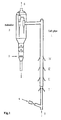
- Fig. 1 - Schematic diagram of the lift pipe reactor of the present invention as an
example
- 1 - Lift pipe
- 2 - Pre-lift gas
- 3 - Subsider
- 4 - Regenerated catalyst
- 5 - Pipeline for stripping steam
- 6 - Outlet of the pyrolyzed gas
- I, II, III, IV are all the feed inlets
-
- Hydrocarbons entering the reactor from different inlets are subjected to different reaction conditions, for light hydrocarbons, which are difficult to pyrolyze, the pyrolysis temperature is higher and the pyrolysis time is longer, while for heavy hydrocarbons, which are difficult to pyrolyze, the reaction temperature is lower and the pyrolysis time is shorter. Hydrocarbons with different properties are fed to the reactor in sequence and the differences in the residence times in the reactor of adjacent hydrocarbons are 0.01-3 s. Hydrocarbons hard to pyrolyze are first fed to the reactor and brought into contact with the catalyst of high temperatures and high activities Born the regenerator and the pyrolysis reaction takes place, at the same time, the catalyst cools down and deactivates and then other hydrocarbon feeds easy to pyrolyze are fed in sequence, the hydrocarbons fed later play a role of quenching those fed earlier.
- This method is usable for the technology in which one or multiple hydrocarbon oil(s) are used as the feed(s), said hydrocarbons include ethane, propane, butane, light hydrocarbons and heavy hydrocarbons. Said heavy hydrocarbons are referred to the hydrocarbons with a distillation range higher than 350°C, including straight run heavy hydrocarbons and secondary processing heavy hydrocarbons, i.e., various straight run wax oils, coker wax oils, straight run vacuum gas oils, atmospheric residues, coker gas oils, thermal cracking heavy oils, solvent-deasphalted oils and various solvent extraction residues of heavy hydrocarbons; said light hydrocarbons are referred to hydrocarbons with a distillation range lower than 350°C, such as LPG, refinery petroleum gases, oil field gases, oil field light hydrocarbons, naphtha and light diesel oil.
- Citing a lift pipe reactor as an example, the particular process is described as follows (see Fig. 1): the regenerated
catalyst 4 from the regenerator enters thelift pipe 1, and then flows upward under the driving of the pre-lifting steam and pre-lifting dry gas introduced from the bottom of the lift pipe; the pre-lifting dry gas is highly pure ethane from the separation zone of the pyrolyzed gas and/or light hydrocarbon gases of other sources containing ethane, steam is added at the same time; ethane quickly pyrolyzes under the action of the hot catalyst at 780-900°C, ethane may also be sprayed from inlet I. A mixture of propane and/or butane from the separation zone and/or other sources and a certain amount of steam is atomized and sprayed from feed inlet II into the lift pipe, where the mixture comes into contact with the mixed stream of the catalyst and the ethane reactant at about 780-850°C and the catalytic pyrolysis reaction takes place. A mixture of the light hydrocarbons having a distillation range lower than 350°C and a certain amount of steam is atomized and sprayed from feed inlet III into the lift pipe, where the mixture comes into contact with the mixture of the catalyst and the upstream reactants at 720-830°C and the catalytic pyrolysis reaction takes place. A mixture of heavy hydrocarbons having a distillation range higher than 350°C and a certain amount of steam is atomized and sprayed from feed inlet IV into the lift pipe, where the mixture comes into contact with the mixture of the catalyst and the upstream reaction stream at about 680-800°C and the catalytic pyrolysis reaction takes place. The distances among the feed inlets for various hydrocarbons are calculated to allow the differences in the residence time of the adjacent hydrocarbons introduced into the reactor in sequence to be 0.01-3 s. Heavier feed oils are sprayed in sequence into the lift pipe at the inlets above the inlets from which the lighter feed oils are sprayed and may play a role of quenching the pyrolyzed stream of lighter feed oils so that the secondary reactions of the pyrolyzed stream of the lighter feed oils are quickly stopped or slowed down. The mixture of the catalyst and the reaction stream of the hydrocarbon feeds in the lift pipe flows upward and enters thesubsider 3, wherein fast separation of gas/solid stream is performed. The reaction stream is removed from theoutlet 6 at the top of the subsider, while the deactivated catalyst drops down along the subsider and is stripped by the stripping steam sprayed from thepipeline 5. The stripped catalyst to be regenerated goes down and enters the regenerator, wherein the coke-burning regeneration reaction is carried out, the regeneration temperature being 700-950°C. During the coke-burning regeneration, the catalyst absorbs a great amount of heat and its temperature rises to 800-900°C. After steam stripping in the transfer pipeline, the high temperature regenerated catalyst is recycled back to the pre-lift section of the lift pipe along the regeneration inclined pipe for reuse. After quenching, the reaction stream removed fromexit 6 enters the fractionation system and separates into pyrolyzed gas and a liquid product rich in aromatics, the pyrolyzed gas is then separated in the separation system into highly pure individual hydrocarbons (CH4, C2H4, C2H6, C3H6, C3H8, C4H8, C4H6, C4H10), wherein the highly pure ethane returns to the bottom of the lift pipe for pyrolysis or is delivered to the ethane pyrolysis heater for pyrolysis. - The components of the special catalyst (LCM) used for the catalytic pyrolysis can be selected from SiO2, Al2O3 and oxides of alkali metals, alkali earth metals and transition metals or mixtures thereof, aluminum silicate modified with oxides of alkali or alkali earth metals can also be used, and optionally, a part of molecular sieves are added.
- If the feed hydrocarbon to be pyrolyzed are two or more in the scope of ethane, propane, butane, light hydrocarbons having a distillation range lower than 350°C and heavy hydrocarbons having a distillation range higher than 350°C, different feeds can enter the device from different positions according to the above method to realize the optimization of the pyrolysis conditions.
- The effect of the present invention. Realization of the pyrolysis of the feeds with different properties under different process conditions results in the optimization of the reaction conditions and product structure, e.g., the yield of ethylene attains 23.76 wt% or higher, as well as savings of capital and operating costs.
- This example is the pyrolysis results using an atmospheric residue and ethane as a co-feed. The pyrolysis test is carried out on a high-low parallel lift pipe pilot-scale device with a total length of the lift pipe being 15.42 m, its internal diameter being 19 mm and a capacity being 0.24 t/d. Ethane, which is difficult to pyrolyze, is first introduced into the lift pipe from the bottom of the lift pipe and brought into contact with the hot and active regenerated catalyst so that reaction takes place, the temperature of the regenerated catalyst at this moment is 820°C, the temperature of the hydrocarbon/catalyst mixture after introducing ethane is 810°C. The inlet of the atmospheric residue is located 4.2 m above the inlet of ethane. The residence time of ethane from the bottom to this point is 0.45 s. The temperature of the mixed stream after introducing the atmospheric residue is 740°C, the temperature at the outlet of the lift pipe is 710°C. The catalyst used in this example is numbered as LCM-A, its properties and composition are shown in Table 1. The process conditions and the material balance in a pilot-scale test of the lift pipe are shown in Table 2. For comparison, the result of the pilot-scale test is also shown when the atmospheric residue and ethane is mixed and fed from the same inlet.
- The results in Table 2 show that, in the technology of ethylene production from atmospheric residues with ethane re-refining, rather optimal pyrolysis conditions for both the atmospheric residue and ethane are realized and the conversions are appropriate when the method of multiple feed at separate point of the present invention are adopted. The yield of ethylene from the individual pyrolysis of the atmospheric residue is 22.36 wt%, while that after the re-refining of 4.56% of ethane attains 25.63 wt%.
- It can also be seen from Table 2 that when the pyrolyzed ethane from the atmospheric residue is not re-refined and additional 6.5 wt% ethane is added, if ethane and the heavy oil are fed from the same feed inlet and the temperature of catalyst/oil mixture is 740°C, the yield of ethylene is only 21.30%; if ethane and the heavy oil are fed into the device from different feed inlets, i.e., the temperature at the inlet for ethane is 810°C and that for the residue is 740°C, the yield of ethylene is 23.76%. Moreover, the aromatic content in the pyrolyzed gasoline is greater than 86 wt%, that in the pyrolyzed liquid product having a distillation range higher than 200°C is greater than 89 wt%.
- This example is the pyrolysis results using an atmospheric residue and a straight run gasoline as a co-feed, the process conditions and the material balance in a pilot-scale test of the lift pipe are shown in Table 3. The straight run gasoline is introduced into the device from the bottom of the lift pipe, the number of the catalyst used is LCM-B, its propertied and composition are seen in Table 1. The temperature of the catalyst/oil mixture is 780°C, the atmospheric residue is sprayed at the position 4.2 m above the inlet of the straight run gasoline, the residence time of the straight run gasoline from the bottom to this point is 0.6 s, and the temperature of the mixed stream after spraying the atmospheric reside is 700°C, the temperature at the outlet of the lift pipe is 660°C
- The results in Table 3 show that, by using the method of mixed feed of the atmospheric residue and the straight run gasoline, the total pyrolysis extent of the mixed feed is rather low when the optimal conditions for the pyrolysis of the atmospheric residue are ensured, in the total material balance, the yields of ethylene and propylene are 21.84% and 12.93%, respectively, either of them is lower than that when only the atmospheric reside is pyrolyzed, indicating that the pyrolysis extent of the straight run gasoline is not high; rather high pyrolysis extent of the straight run gasoline is attained while ensuring that the pyrolysis of the atmospheric residue proceeds under the optimal conditions by using the method of the multiple feed at separate point of the present invention: in the total material balance of the mixed feed, the yield of ethylene reaches 24.50%, that of propylene reaches 14.51%, either of them exceeds that when only the atmospheric residue is pyrolyzed.
Properties and composition of the catalyst Item Catalyst LCM-A Catalyst LCM-B Type of the active component Alkali earth metal Oxides Transition metal oxides Chemical composition Al2O3, wt% 40 42 Na2O, wt% <0.3 <0.3 Fe2O3, wt% 0.8 0.8 Active component, wt% 8.2 6.5 Specific surface, m2/g 58 65 Porosity, ml/g 0.12 0.13 Bulk density, g/ml 0.85 0.85 Sieve composition, wt% 0-20 µ 2.6 3.2 20-40 µ 19.4 20.2 40-60 µ 31.5 32.1 60-80 µ 24.7 23.9 >80 µ 21.8 20.6 Pyrolysis result using ethane and an atmospheric residue Item Material balance for the pyrolysis of the atmospheric residue Material balance for the pyrolysis of the atmospheric residue and ethane Feeding mode Single Separate Mixed Separate Whether ethane is refined No Yes No No Ethane content in feed, wt% 0.0 0.0 6.5 6.5 Temp. of regeneration bed, °C 820 820 820 820 Temp. of stripping steam for regenerated catalyst, °C 400 400 400 400 Stream temp. after spraying ethane, °C / 810 740 810 Stream temp. after spraying atmospheric residue, °C 740 740 740 740 Temp. at the outlet of lift pipe, °C 710 710 710 710 Temp. after quenching, °C 600 600 600 600 Catalyst type A A A A Steam/hydrocarbon ratio, wt/wt 0.23 0.23 0.23 0.23 Catalyst/oil ratio, wt/wt 18.0 18.0 18.0 10 Yield of major products, wt% Hydrogen 0.87 1.09 0.84 1.03 Methane 11.44 11.81 10.76 11.13 Ethylene 22.36 25.63 21.30 23.76 Ethane 4.56 / 10.20 6.79 Propylene 12.86 13.25 12.05 12.21 Propane 0.71 0.72 0.67 0.68 Butane 0.22 0.22 0.21 0.21 Butylene 3.04 3.10 2.85 2.90 Butadiene 1.87 1.91 1.75 1.76 Pyrolyzed gasoline (<200°C) 12.46 12.76 11.68 11.85 Pyrolyzed middle distillate 5.23 5.24 4.94 4.89 Pyrolyzed heavy oil (>300°C) 9.86 9.88 9.30 9.22 Coke 13.23 13.27 12.40 12.37 Loss 1.29 1.12 1.05 1.21 Where: (1) Aromatic content in pyrolyzed gasoline 88.12 87.75 86.54 87.87 (2) Aromatic content in the pyrolyzed product having a distillation range higher than 200°C 90.13 89.89 90.10 91.39 Pyrolysis result using straight run gasoline and an atmospheric residue Item Material balance for the pyrolysis of atmospheric residue Material balance for pyrolysis of straight run gasoline Material balance for pyrolysis of atmospheric residue and straight run gasoline Feeding mode Single Single Mixed Separate Gasoline proportion in feed, wt% 0.0 100 20 20 Temp. of regeneration bed, °C 800 / 800 800 Temp. of stripping steam for regenerated catalyst, °C 400 / 400 400 Stream temp. after spraying gasoline, °C / 780 700 780 Stream temp. after spraying atmospheric residue,°C 700 700 700 700 Temp. at the outlet of the lift pipe, °C Temp. after quenching, °C 660 660 660 660 Catalyst type 600 600 600 600 Steam/hydrocarbon ratio, wt/wt B B B B Catalyst/oil ratio, wt/wt 0.25 / 0.25 0.25 18.6 / 19.2 19.0 Yield of major products, wt% Ethylene 23.05 30.30 21.84 24.50 Propylene 14.01 16.51 12.93 14.51 C4 olefins 6.73 8.48 6.24 7.08 Pyrolyzed gasoline (<200°C) 13.45 19.20 23.16 14.60 Pyrolyzed middle distillate 6.60 2.00 5.50 5.68 Pyrolyzed heavy oil (>300°C) 9.31 0.01 7.45 7.45 Coke plus loss 9.00 0.50 7.30 7.30 Where: (1) Aromatic content in pyrolyzed gasoline 88.44 92.30 78.52 89.10 (2) Aromatic content in the pyrolyzed product having a distillation range higher than 200°C 92.65 / 92.50 93.76
Claims (11)
- A process for catalytic pyrolysis of hydrocarbon feeds to produce lower olefins with stress on ethylene and co-produce light aromatics, in which the hydrocarbon feeds are brought into contact with a solid granular catalyst in a piston flow reactor to proceed catalytic pyrolysis, the hydrocarbon feeds including two or more hydrocarbons having different physicochemical properties, the feed hydrocarbons being mixed with steam and introduced, the general reaction conditions in the reaction zone being: temperature 600-900°C, pressure 0.13-0.40 MPa (absolute), total steam/hydrocarbon ratio 0.1-1.0, total catalyst/oil ratio 5-100 and the catalyst/oil contact time 0.02-5 s; the oil gas after reaction is separated quickly from the catalyst and quenched, the catalyst is recycled for reuse after regeneration; different feeds are introduced from different positions, hydrocarbons difficult to pyrolyze are first introduced into the reactor and brought into contact with the catalyst of high temperatures and high activities from the regenerator and the pyrolysis takes place, meanwhile, the catalyst cools down and deactivates; other hydrocarbons easier to pyrolyze are introduced in sequence from the upstream to downstream of the reaction zone, the hydrocarbons introduced later play a role of quenching those introduced earlier, the temperature of the reaction zone and the activity of the catalyst are lowered step by step from the upstream to the downstream; the positions from which various hydrocarbons enter the reactor are determined as such that the residence times of various hydrocarbons in the reactor are gradually decreased in the sequence from difficulty to ease in pyrolysis, the differences in the residence times of every adjacent two hydrocarbon feeds in the reactor are 0.01-3 s.
- A process according to claim 1, wherein the hydrocarbon feeds having different physicochemical properties include ethane, propane, butane, light hydrocarbons with a distillation range lower than 350°C, and heavy hydrocarbons with a distillation range higher than 350°C.
- A process according to claim 2, wherein the light hydrocarbons with a distillation range lower than 350°C include LPG, refinery petroleum gases, oil field gases, oil field light hydrocarbons, naphtha and light diesel oil; the heavy hydrocarbons with a distillation range higher than 350°C include straight run and secondary processing heavy hydrocarbons, i.e., straight run wax oils, coker wax oils, straight run vacuum gas oils, atmospheric residues, coker gas oils, thermal cracking heavy oils, solvent-deasphalted oils and various residues from solvent extraction of heavy hydrocarbons.
- A process according to claim 2, wherein the controlled temperature ranges for various hydrocarbons are: ethane, 780-900°C; propane and/or butane, 750-850°C; the light hydrocarbons with a distillation range higher lower than 350°C, 720-830°C; and the heavy hydrocarbons with a distillation range higher than 350°C, 680-800°C.
- A process according to claim 3 or 4, wherein the two hydrocarbon feeds are ethane and atmospheric residues respectively.
- A process according to claim 1-4, wherein the components of the pyrolysis catalyst used can be selected from SiO2, Al2O3 and oxides of alkali metals, alkali earth metals and transition metals or mixtures thereof, aluminum silicate modified with oxides of alkali or alkali earth metals can also be used, and optionally, a part of molecular sieves are added.
- A process according to claim 1, wherein, the deactivated catalyst is delivered to the regenerator for regeneration by burning off the coke after stream stripping; the regeneration temperature is 750-950°C, the high temperature regenerated catalyst is drawn after steam stripping and recycled back to the reactor through the inclined pipe for reuse.
- A process for direct conversion of heavy hydrocarbon to produce lower olefins with stress on ethylene and co-produce light aromatics, in which the hydrocarbon feed is bought into contact with a solid granular catalyst in a piston flow reactor to proceed catalytic pyrolysis, the feed hydrocarbon is mixed with steam and introduced, the general reaction conditions in the reaction zone are: temperature 600-900°C, pressure 0.13-0.40 MPa (absolute), total steam/hydrocarbon ratio 0.1-1.0, total catalyst/oil ratio 5-100 and the catalyst/oil contact time 0.02-5 s; the oil gas after reaction is separated quickly from the catalyst and quenched, the catalyst is recycled for reuse after regeneration; the oil gas enters a fractionation and separation system to proceed the separation, a product gas mainly containing ethylene, the by-product ethane, and a liquid product rich in aromatics can be obtained; the highly pure by-product ethane from the separation system and/or the gases containing ethane from other sources return to the pyrolysis reactor of the piston flow type from the upstream inlet of the reactor and come into contact with the catalyst of high temperatures and high activities, fast pyrolysis takes place at temperatures higher than 780°C to produce ethylene and meanwhile, the catalyst cools down and deactivates, steam is introduced at the same time when ethane feed is introduced from the upstream inlet of the reactor; heavy hydrocarbon feed is introduced at position certain distances from downstream of the inlet for ethane, the hydrocarbon introduced later play a role of quenching those introduced earlier, the reaction temperature at this moment is lowered to 680-800°C; the feeding positions of the by-product ethane and the heavy hydrocarbon are determined as such that the residence time of ethane, which is difficult to pyrolyze, is long, while that of heavy hydrocarbon, which are easy to pyrolyze, is short, the differences in the residence times of ethane and heavy hydrocarbons in the reactor are 0.01-3 s.
- A process according to claim 8, wherein the heavy hydrocarbon is the hydrocarbon having a distillation range higher than 350°C, including straight run heavy hydrocarbons and secondary processing heavy hydrocarbons, i.e., straight run wax oils, coker wax oils, straight run vacuum gas oils, atmospheric residues, coker gas oils, thermal cracking heavy oils, solvent-deasphalted oils and various residues from solvent extraction of heavy hydrocarbons.
- A process according to claim 8 or 9, wherein the components of the catalyst used for pyrolysis can be selected from SiO2, Al2O3 and oxides of alkali metals, alkali earth metals and transition metals or mixtures thereof, aluminum silicate modified with oxides of alkali or alkali earth metals can also be used, and optionally, a part of molecular sieves are added.
- A process according to claim 8 or 9, wherein the deactivated catalyst is delivered to the regenerator for regeneration by burning off the coke after stream stripping, the regeneration temperature is 750-950°C, the high temperature regenerated catalyst is drawn after stripping and recycled back to the reactor through the inclined pipe for reuse.
Applications Claiming Priority (2)
| Application Number | Priority Date | Filing Date | Title |
|---|---|---|---|
| CN97119048A CN1056595C (en) | 1997-10-20 | 1997-10-20 | Process for direct-conversion preparation olefines from multiple fed hydrocarbon |
| CN97119048 | 1997-10-20 |
Publications (2)
| Publication Number | Publication Date |
|---|---|
| EP0911308A1 true EP0911308A1 (en) | 1999-04-28 |
| EP0911308B1 EP0911308B1 (en) | 2002-11-27 |
Family
ID=5175152
Family Applications (1)
| Application Number | Title | Priority Date | Filing Date |
|---|---|---|---|
| EP98119730A Expired - Lifetime EP0911308B1 (en) | 1997-10-20 | 1998-10-20 | Process for the preparation of olefins by direct conversion of multiple hydrocarbons |
Country Status (4)
| Country | Link |
|---|---|
| US (1) | US6420621B2 (en) |
| EP (1) | EP0911308B1 (en) |
| CN (1) | CN1056595C (en) |
| DE (1) | DE69809685T2 (en) |
Cited By (7)
| Publication number | Priority date | Publication date | Assignee | Title |
|---|---|---|---|---|
| FR2829143A1 (en) * | 2001-08-29 | 2003-03-07 | China Petroleum & Chemical | Catalytic cracking of petroleum hydrocarbons comprises use of double tube reactor, producing reaction streams for separation into lighter products |
| US6867341B1 (en) | 2002-09-17 | 2005-03-15 | Uop Llc | Catalytic naphtha cracking catalyst and process |
| EP2690159A1 (en) * | 2011-03-25 | 2014-01-29 | JX Nippon Oil & Energy Corporation | Method for producing single-ring aromatic hydrocarbons |
| WO2017065810A1 (en) * | 2015-10-14 | 2017-04-20 | Saudi Arabian Oil Company | Processes and systems for fluidized catalytic cracking |
| EP3225678A3 (en) * | 2004-03-08 | 2018-01-03 | China Petroleum & Chemical Corporation | Am fcc process with two reaction zones |
| US9862897B2 (en) | 2013-02-21 | 2018-01-09 | Jx Nippon Oil & Energy Corporation | Method for producing monocyclic aromatic hydrocarbon |
| US10087376B2 (en) | 2010-01-20 | 2018-10-02 | Jx Nippon Oil & Energy Corporation | Method for producing monocyclic aromatic hydrocarbons |
Families Citing this family (31)
| Publication number | Priority date | Publication date | Assignee | Title |
|---|---|---|---|---|
| US20050085677A1 (en) * | 2003-10-15 | 2005-04-21 | Fina Technology, Inc. | Method for improved production of cyclohexenyl and alkenyl aromatic compounds |
| CN100487080C (en) * | 2004-03-08 | 2009-05-13 | 中国石油化工股份有限公司 | Chemical oil-refining method for preparing low carbon olefin and arene |
| US7560020B2 (en) * | 2006-10-30 | 2009-07-14 | Exxonmobil Chemical Patents Inc. | Deasphalting tar using stripping tower |
| CN101362669B (en) * | 2007-08-09 | 2012-12-12 | 中国石油化工股份有限公司 | Catalytic conversion method of ethylene, propylene and aromatic hydrocarbon preparation |
| CN101362959B (en) * | 2007-08-09 | 2012-09-05 | 中国石油化工股份有限公司 | Catalytic conversion method for preparing propone and high-octane number gasoline |
| DK2184335T3 (en) * | 2007-08-09 | 2021-06-07 | China Petroleum & Chem Corp | PROCEDURE FOR CATALYTIC TRANSFORMATION |
| EP2364343B1 (en) * | 2008-12-10 | 2017-09-06 | Reliance Industries Limited | A fluid catalytic cracking (fcc) process for manufacturing propylene and ethylene in increased yield |
| CN101760227B (en) * | 2008-12-25 | 2013-06-05 | 中国石油化工股份有限公司 | Catalytic conversion method for preparing propylene and high octane gasoline |
| WO2010073841A1 (en) | 2008-12-26 | 2010-07-01 | 新日本石油株式会社 | Method for refining dicyclopentadiene |
| US9458390B2 (en) * | 2009-07-01 | 2016-10-04 | Exxonmobil Chemical Patents Inc. | Process and system for preparation of hydrocarbon feedstocks for catalytic cracking |
| US9181146B2 (en) | 2010-12-10 | 2015-11-10 | Exxonmobil Chemical Patents Inc. | Process for the production of xylenes and light olefins |
| CN108947938A (en) | 2011-01-24 | 2018-12-07 | 国际壳牌研究有限公司 | The preparation method of ethylene oxide |
| CN103391929A (en) * | 2011-01-24 | 2013-11-13 | 国际壳牌研究有限公司 | Process for the production of ethylene oxide |
| US8937205B2 (en) | 2012-05-07 | 2015-01-20 | Exxonmobil Chemical Patents Inc. | Process for the production of xylenes |
| US9181147B2 (en) | 2012-05-07 | 2015-11-10 | Exxonmobil Chemical Patents Inc. | Process for the production of xylenes and light olefins |
| US8921633B2 (en) | 2012-05-07 | 2014-12-30 | Exxonmobil Chemical Patents Inc. | Process for the production of xylenes and light olefins |
| EP3013395B1 (en) | 2013-06-28 | 2019-10-02 | Duc Hong Le | Catheter anchoring device and method |
| US10767117B2 (en) | 2017-04-25 | 2020-09-08 | Saudi Arabian Oil Company | Enhanced light olefin yield via steam catalytic downer pyrolysis of hydrocarbon feedstock |
| US10870802B2 (en) | 2017-05-31 | 2020-12-22 | Saudi Arabian Oil Company | High-severity fluidized catalytic cracking systems and processes having partial catalyst recycle |
| US10889768B2 (en) | 2018-01-25 | 2021-01-12 | Saudi Arabian Oil Company | High severity fluidized catalytic cracking systems and processes for producing olefins from petroleum feeds |
| CN110724550B (en) * | 2018-07-16 | 2021-04-06 | 中国石油化工股份有限公司 | Method and system for catalytic cracking by adopting fast fluidized bed |
| US11066606B2 (en) | 2019-11-12 | 2021-07-20 | Saudi Arabian Oil Company | Systems and methods for catalytic upgrading of vacuum residue to distillate fractions and olefins with steam |
| US11066605B2 (en) | 2019-11-12 | 2021-07-20 | Saudi Arabian Oil Company | Systems and methods for catalytic upgrading of vacuum residue to distillate fractions and olefins |
| US11352575B2 (en) | 2020-09-01 | 2022-06-07 | Saudi Arabian Oil Company | Processes for producing petrochemical products that utilize hydrotreating of cycle oil |
| US11332680B2 (en) | 2020-09-01 | 2022-05-17 | Saudi Arabian Oil Company | Processes for producing petrochemical products that utilize fluid catalytic cracking of lesser and greater boiling point fractions with steam |
| US11230673B1 (en) | 2020-09-01 | 2022-01-25 | Saudi Arabian Oil Company | Processes for producing petrochemical products that utilize fluid catalytic cracking of a lesser boiling point fraction with steam |
| US11230672B1 (en) | 2020-09-01 | 2022-01-25 | Saudi Arabian Oil Company | Processes for producing petrochemical products that utilize fluid catalytic cracking |
| US11242493B1 (en) | 2020-09-01 | 2022-02-08 | Saudi Arabian Oil Company | Methods for processing crude oils to form light olefins |
| US11505754B2 (en) | 2020-09-01 | 2022-11-22 | Saudi Arabian Oil Company | Processes for producing petrochemical products from atmospheric residues |
| US11434432B2 (en) | 2020-09-01 | 2022-09-06 | Saudi Arabian Oil Company | Processes for producing petrochemical products that utilize fluid catalytic cracking of a greater boiling point fraction with steam |
| CN112973579B (en) * | 2021-02-07 | 2022-04-12 | 中国科学院过程工程研究所 | Gas-solid short contact time reaction device and application thereof |
Citations (1)
| Publication number | Priority date | Publication date | Assignee | Title |
|---|---|---|---|---|
| US5506365A (en) * | 1987-12-30 | 1996-04-09 | Compagnie De Raffinage Et De Distribution Total France | Process and apparatus for fluidized-bed hydrocarbon conversion |
Family Cites Families (15)
| Publication number | Priority date | Publication date | Assignee | Title |
|---|---|---|---|---|
| GB1493888A (en) | 1975-09-25 | 1977-11-30 | British Petroleum Co | Olefins production |
| US4291185A (en) * | 1978-12-14 | 1981-09-22 | Mobil Oil Corporation | Alkylation of benzene in petroleum |
| JPS585225B2 (en) | 1978-12-21 | 1983-01-29 | 工業技術院長 | Method of heating coke particles |
| US4242100A (en) * | 1979-10-15 | 1980-12-30 | Tri-Pak, Inc. | Motor fuel composition |
| US4320241A (en) * | 1980-08-28 | 1982-03-16 | Occidental Research Corporation | Process for converting oxygenated hydrocarbons into hydrocarbons |
| US4422925A (en) * | 1981-12-28 | 1983-12-27 | Texaco Inc. | Catalytic cracking |
| US4670021A (en) * | 1983-01-10 | 1987-06-02 | Texaco Inc. | Detergent and corrosion inhibiting additive and motor fuel composition containing same |
| US4663019A (en) | 1984-03-09 | 1987-05-05 | Stone & Webster Engineering Corp. | Olefin production from heavy hydrocarbon feed |
| US4693991A (en) * | 1986-05-02 | 1987-09-15 | Phillips Petroleum Company | Hydrotreating catalyst composition |
| FR2625509B1 (en) * | 1987-12-30 | 1990-06-22 | Total France | METHOD AND DEVICE FOR CONVERTING HYDROCARBONS INTO A FLUIDIZED BED |
| US5173174A (en) * | 1988-07-07 | 1992-12-22 | Uop | Metal-tolerant FCC catalyst and process |
| ATE89308T1 (en) | 1989-02-08 | 1993-05-15 | Stone & Webster Eng Corp | PROCESS FOR PRODUCTION OF OLEFINS. |
| FR2654435B1 (en) * | 1989-11-10 | 1992-03-13 | Total France | METHOD AND APPARATUS FOR CONTACTING A HYDROCARBON LOAD WITH HOT SOLID PARTICLES IN A TUBULAR REACTOR WITH AN ASCENDING FLUIDIZED BED. |
| JP2966985B2 (en) * | 1991-10-09 | 1999-10-25 | 出光興産株式会社 | Catalytic hydrotreating method for heavy hydrocarbon oil |
| CN1030313C (en) * | 1992-07-16 | 1995-11-22 | 中国石油化工总公司 | Method for preparing ethene by direct conversion of heavy hydrocarbon |
-
1997
- 1997-10-20 CN CN97119048A patent/CN1056595C/en not_active Expired - Fee Related
-
1998
- 1998-10-19 US US09/174,462 patent/US6420621B2/en not_active Expired - Lifetime
- 1998-10-20 EP EP98119730A patent/EP0911308B1/en not_active Expired - Lifetime
- 1998-10-20 DE DE69809685T patent/DE69809685T2/en not_active Expired - Lifetime
Patent Citations (1)
| Publication number | Priority date | Publication date | Assignee | Title |
|---|---|---|---|---|
| US5506365A (en) * | 1987-12-30 | 1996-04-09 | Compagnie De Raffinage Et De Distribution Total France | Process and apparatus for fluidized-bed hydrocarbon conversion |
Cited By (13)
| Publication number | Priority date | Publication date | Assignee | Title |
|---|---|---|---|---|
| FR2829143A1 (en) * | 2001-08-29 | 2003-03-07 | China Petroleum & Chemical | Catalytic cracking of petroleum hydrocarbons comprises use of double tube reactor, producing reaction streams for separation into lighter products |
| US6867341B1 (en) | 2002-09-17 | 2005-03-15 | Uop Llc | Catalytic naphtha cracking catalyst and process |
| US7314964B2 (en) | 2002-09-17 | 2008-01-01 | Uop Llc | Catalytic naphtha cracking catalyst and process |
| US7446071B2 (en) | 2002-09-17 | 2008-11-04 | Uop Llc | Catalytic naphtha cracking catalyst and process |
| US7585489B2 (en) | 2002-09-17 | 2009-09-08 | Uop Llc | Catalytic naphtha cracking catalyst and process |
| EP3225678A3 (en) * | 2004-03-08 | 2018-01-03 | China Petroleum & Chemical Corporation | Am fcc process with two reaction zones |
| US10087376B2 (en) | 2010-01-20 | 2018-10-02 | Jx Nippon Oil & Energy Corporation | Method for producing monocyclic aromatic hydrocarbons |
| EP2690159A4 (en) * | 2011-03-25 | 2014-09-03 | Jx Nippon Oil & Energy Corp | Method for producing single-ring aromatic hydrocarbons |
| US9233892B2 (en) | 2011-03-25 | 2016-01-12 | Jx Nippon Oil & Energy Corporation | Method for producing monocyclic aromatic hydrocarbons |
| EP2690159A1 (en) * | 2011-03-25 | 2014-01-29 | JX Nippon Oil & Energy Corporation | Method for producing single-ring aromatic hydrocarbons |
| US9862897B2 (en) | 2013-02-21 | 2018-01-09 | Jx Nippon Oil & Energy Corporation | Method for producing monocyclic aromatic hydrocarbon |
| WO2017065810A1 (en) * | 2015-10-14 | 2017-04-20 | Saudi Arabian Oil Company | Processes and systems for fluidized catalytic cracking |
| CN108350367A (en) * | 2015-10-14 | 2018-07-31 | 沙特阿拉伯石油公司 | The method and system of fluid catalytic cracking |
Also Published As
| Publication number | Publication date |
|---|---|
| DE69809685D1 (en) | 2003-01-09 |
| JP3953208B2 (en) | 2007-08-08 |
| DE69809685T2 (en) | 2003-04-10 |
| JPH11193250A (en) | 1999-07-21 |
| CN1056595C (en) | 2000-09-20 |
| EP0911308B1 (en) | 2002-11-27 |
| CN1215041A (en) | 1999-04-28 |
| US20010056216A1 (en) | 2001-12-27 |
| US6420621B2 (en) | 2002-07-16 |
Similar Documents
| Publication | Publication Date | Title |
|---|---|---|
| EP0911308B1 (en) | Process for the preparation of olefins by direct conversion of multiple hydrocarbons | |
| US11306258B2 (en) | Enhanced light olefin yield via steam catalytic downer pyrolysis of hydrocarbon feedstock | |
| KR100281750B1 (en) | Method and apparatus for preparing low molecular weight olefins | |
| CN110540869B (en) | Catalytic cracking method | |
| CN101323798B (en) | Catalytic conversion method and special apparatus therefor | |
| CN102952577B (en) | Catalytic conversion method for increasing propylene yield | |
| US4828681A (en) | Process of thermally cracking hydrocarbons using particulate solids as heat carrier | |
| US9162955B2 (en) | Process for pyrolysis of a coal feed | |
| CN103540345A (en) | Catalytic cracking method | |
| CN102086402B (en) | Catalytic cracking method and device capable of increasing propylene yield and improving properties of gasoline | |
| US5220093A (en) | Process for production of olefins from mixtures of light paraffins | |
| EP1713884B1 (en) | Method for selective component cracking to maximize production of light olefins | |
| WO2019228131A1 (en) | Catalytic reaction regeneration method for increasing yield of propylene | |
| CN110540866B (en) | Processing method of crude oil whole fraction | |
| CN109232153A (en) | A kind of method that naphtha prepares low-carbon alkene | |
| JP3953208B6 (en) | Optimized olefin production process by direct conversion of multiple hydrocarbons | |
| CN114606020B (en) | Ethylene and propylene production system and method | |
| CN113735676B (en) | Method for high-selectivity catalytic pyrolysis of high-yield propylene and high-yield gasoline | |
| CN101362960A (en) | Catalytic conversion method for preparing high-octane number gasoline | |
| CN101205477A (en) | Low energy consumption catalytic conversion method of hydrocarbon oil | |
| CN116376591A (en) | Method and device for co-producing low-carbon olefin and high-octane gasoline by Fischer-Tropsch synthesis product | |
| CN115895710A (en) | Catalytic conversion method and device for producing low-carbon olefin | |
| CN115992003A (en) | Method and reactor for preparing low-carbon olefin and aromatic hydrocarbon by catalytic conversion of hydrocarbon raw material as reaction raw material | |
| CN117304972A (en) | Dual-catalyst catalytic cracking device and method for improving yield of low-carbon olefin and gasoline and diesel oil | |
| CN115992006A (en) | Reaction method and reactor for preparing low-carbon olefin and aromatic hydrocarbon by fluidization catalytic conversion of hydrocarbon raw material as reaction raw material |
Legal Events
| Date | Code | Title | Description |
|---|---|---|---|
| PUAI | Public reference made under article 153(3) epc to a published international application that has entered the european phase |
Free format text: ORIGINAL CODE: 0009012 |
|
| AK | Designated contracting states |
Kind code of ref document: A1 Designated state(s): DE FR |
|
| AX | Request for extension of the european patent |
Free format text: AL;LT;LV;MK;RO;SI |
|
| 17P | Request for examination filed |
Effective date: 19990802 |
|
| AKX | Designation fees paid |
Free format text: DE FR |
|
| 17Q | First examination report despatched |
Effective date: 20010313 |
|
| GRAG | Despatch of communication of intention to grant |
Free format text: ORIGINAL CODE: EPIDOS AGRA |
|
| GRAG | Despatch of communication of intention to grant |
Free format text: ORIGINAL CODE: EPIDOS AGRA |
|
| GRAH | Despatch of communication of intention to grant a patent |
Free format text: ORIGINAL CODE: EPIDOS IGRA |
|
| GRAH | Despatch of communication of intention to grant a patent |
Free format text: ORIGINAL CODE: EPIDOS IGRA |
|
| GRAA | (expected) grant |
Free format text: ORIGINAL CODE: 0009210 |
|
| AK | Designated contracting states |
Kind code of ref document: B1 Designated state(s): DE FR |
|
| REF | Corresponds to: |
Ref document number: 69809685 Country of ref document: DE Date of ref document: 20030109 |
|
| ET | Fr: translation filed | ||
| PLBE | No opposition filed within time limit |
Free format text: ORIGINAL CODE: 0009261 |
|
| STAA | Information on the status of an ep patent application or granted ep patent |
Free format text: STATUS: NO OPPOSITION FILED WITHIN TIME LIMIT |
|
| 26N | No opposition filed |
Effective date: 20030828 |
|
| REG | Reference to a national code |
Ref country code: FR Ref legal event code: PLFP Year of fee payment: 19 |
|
| REG | Reference to a national code |
Ref country code: FR Ref legal event code: PLFP Year of fee payment: 20 |
|
| PGFP | Annual fee paid to national office [announced via postgrant information from national office to epo] |
Ref country code: FR Payment date: 20170918 Year of fee payment: 20 |
|
| PGFP | Annual fee paid to national office [announced via postgrant information from national office to epo] |
Ref country code: DE Payment date: 20171018 Year of fee payment: 20 |
|
| REG | Reference to a national code |
Ref country code: DE Ref legal event code: R071 Ref document number: 69809685 Country of ref document: DE |