EP0911138A1 - Injection molding apparatus having inter-manifold melt transfer bushings - Google Patents
Injection molding apparatus having inter-manifold melt transfer bushings Download PDFInfo
- Publication number
- EP0911138A1 EP0911138A1 EP98120039A EP98120039A EP0911138A1 EP 0911138 A1 EP0911138 A1 EP 0911138A1 EP 98120039 A EP98120039 A EP 98120039A EP 98120039 A EP98120039 A EP 98120039A EP 0911138 A1 EP0911138 A1 EP 0911138A1
- Authority
- EP
- European Patent Office
- Prior art keywords
- melt
- distribution manifold
- extending
- injection molding
- molding apparatus
- Prior art date
- Legal status (The legal status is an assumption and is not a legal conclusion. Google has not performed a legal analysis and makes no representation as to the accuracy of the status listed.)
- Granted
Links
- 238000001746 injection moulding Methods 0.000 title claims abstract description 45
- 239000000155 melt Substances 0.000 claims abstract description 33
- 238000000465 moulding Methods 0.000 claims abstract description 11
- 238000000926 separation method Methods 0.000 claims abstract description 10
- 125000006850 spacer group Chemical group 0.000 claims abstract description 10
- 238000010438 heat treatment Methods 0.000 claims description 10
- 230000007246 mechanism Effects 0.000 claims description 6
- 238000007789 sealing Methods 0.000 claims 1
- 239000000463 material Substances 0.000 abstract description 33
- 238000002347 injection Methods 0.000 abstract description 12
- 239000007924 injection Substances 0.000 abstract description 12
- 230000004888 barrier function Effects 0.000 description 24
- 229920000139 polyethylene terephthalate Polymers 0.000 description 19
- 239000005020 polyethylene terephthalate Substances 0.000 description 19
- 229920000219 Ethylene vinyl alcohol Polymers 0.000 description 5
- 238000001816 cooling Methods 0.000 description 5
- 239000004677 Nylon Substances 0.000 description 4
- 229920001778 nylon Polymers 0.000 description 4
- 239000004715 ethylene vinyl alcohol Substances 0.000 description 3
- 235000013361 beverage Nutrition 0.000 description 2
- -1 polyethylene terephthalate Polymers 0.000 description 2
- 239000000161 steel melt Substances 0.000 description 2
- 229920000297 Rayon Polymers 0.000 description 1
- 229910000831 Steel Inorganic materials 0.000 description 1
- 229910001069 Ti alloy Inorganic materials 0.000 description 1
- 229910001315 Tool steel Inorganic materials 0.000 description 1
- 230000000903 blocking effect Effects 0.000 description 1
- 239000000498 cooling water Substances 0.000 description 1
- 238000012986 modification Methods 0.000 description 1
- 230000004048 modification Effects 0.000 description 1
- 230000001681 protective effect Effects 0.000 description 1
- 238000005086 pumping Methods 0.000 description 1
- 230000000717 retained effect Effects 0.000 description 1
- 239000010959 steel Substances 0.000 description 1
- XLYOFNOQVPJJNP-UHFFFAOYSA-N water Substances O XLYOFNOQVPJJNP-UHFFFAOYSA-N 0.000 description 1
Images


Classifications
-
- B—PERFORMING OPERATIONS; TRANSPORTING
- B29—WORKING OF PLASTICS; WORKING OF SUBSTANCES IN A PLASTIC STATE IN GENERAL
- B29C—SHAPING OR JOINING OF PLASTICS; SHAPING OF MATERIAL IN A PLASTIC STATE, NOT OTHERWISE PROVIDED FOR; AFTER-TREATMENT OF THE SHAPED PRODUCTS, e.g. REPAIRING
- B29C45/00—Injection moulding, i.e. forcing the required volume of moulding material through a nozzle into a closed mould; Apparatus therefor
- B29C45/17—Component parts, details or accessories; Auxiliary operations
- B29C45/26—Moulds
- B29C45/27—Sprue channels ; Runner channels or runner nozzles
- B29C45/2725—Manifolds
-
- B—PERFORMING OPERATIONS; TRANSPORTING
- B29—WORKING OF PLASTICS; WORKING OF SUBSTANCES IN A PLASTIC STATE IN GENERAL
- B29C—SHAPING OR JOINING OF PLASTICS; SHAPING OF MATERIAL IN A PLASTIC STATE, NOT OTHERWISE PROVIDED FOR; AFTER-TREATMENT OF THE SHAPED PRODUCTS, e.g. REPAIRING
- B29C45/00—Injection moulding, i.e. forcing the required volume of moulding material through a nozzle into a closed mould; Apparatus therefor
- B29C45/16—Making multilayered or multicoloured articles
- B29C45/1603—Multi-way nozzles specially adapted therefor
-
- B—PERFORMING OPERATIONS; TRANSPORTING
- B29—WORKING OF PLASTICS; WORKING OF SUBSTANCES IN A PLASTIC STATE IN GENERAL
- B29C—SHAPING OR JOINING OF PLASTICS; SHAPING OF MATERIAL IN A PLASTIC STATE, NOT OTHERWISE PROVIDED FOR; AFTER-TREATMENT OF THE SHAPED PRODUCTS, e.g. REPAIRING
- B29C45/00—Injection moulding, i.e. forcing the required volume of moulding material through a nozzle into a closed mould; Apparatus therefor
- B29C45/17—Component parts, details or accessories; Auxiliary operations
- B29C45/26—Moulds
- B29C45/27—Sprue channels ; Runner channels or runner nozzles
- B29C45/2725—Manifolds
- B29C2045/273—Manifolds stacked manifolds
-
- B—PERFORMING OPERATIONS; TRANSPORTING
- B29—WORKING OF PLASTICS; WORKING OF SUBSTANCES IN A PLASTIC STATE IN GENERAL
- B29C—SHAPING OR JOINING OF PLASTICS; SHAPING OF MATERIAL IN A PLASTIC STATE, NOT OTHERWISE PROVIDED FOR; AFTER-TREATMENT OF THE SHAPED PRODUCTS, e.g. REPAIRING
- B29C45/00—Injection moulding, i.e. forcing the required volume of moulding material through a nozzle into a closed mould; Apparatus therefor
- B29C45/17—Component parts, details or accessories; Auxiliary operations
- B29C45/26—Moulds
- B29C45/27—Sprue channels ; Runner channels or runner nozzles
- B29C2045/277—Spacer means or pressure pads between manifold and mould plates
Definitions
- This invention relates generally to multi-layer injection molding apparatus and more particularly to such apparatus having melt transfer bushings extending from a rear melt distribution manifold across an insulative air space into bores extending through a front melt distribution manifold.
- Injection molding apparatus for making multi-layered protective containers for food or preforms or parisons for beverage bottles are well known.
- the inner and outer layers are made of a polyethylene terephthalate (PET) type material with one or more barrier layers made of a material such as ethylene vinyl alcohol copolymer (EVOH) or nylon.
- PET polyethylene terephthalate
- EVOH ethylene vinyl alcohol copolymer
- nylon ethylene vinyl alcohol copolymer
- the two different melts are distributed through a single melt distribution manifold having different passages. However, preferably for materials such as these having different injection temperatures of about 565°F and 400°F respectively, the two melts are distributed through two different melt distribution manifolds. In some cases, the two melts are injected sequentially, while in other cases both coinjection and sequential injection are utilized.
- the two materials are injected through heated nozzles, each having a central melt channel and one or more annular melt channels extending around the central melt channel to a gate leading to the cavity.
- the invention provides a multi-cavity hot runner injection molding apparatus for multi-layer molding having a front melt distribution manifold and a rear melt distribution manifold mounted in a mold extending substantially parallel to each other with an insulative air space therebetween.
- a number of heated nozzles each having a rear end, a front end and a central melt channel extending therethrough from the rear end to the front end.
- Each heated nozzle has an inner annular melt channel extending to the front end around the central melt channel with a melt bore extending from the rear end of the heated nozzle to the inner annular melt channel.
- It also has an outer annular melt channel extending to the front end around the central melt channel and the inner annular melt channel with one or more melt bores extending from the rear end of the heated nozzle to the outer annular melt channel.
- the heated nozzles are mounted in the mold with the rear end of each heated nozzle abutting against the front melt distribution manifold.
- a first melt passage from a first melt source branches in the front melt distribution manifold and divides again to extend through the central melt channel and the one or more melt bores extending from the rear end of the heated nozzle to the outer annular melt channel and the outer annular melt channel in each heated nozzle to a gate adjacent the front end of the heated nozzle leading to a cavity in the mold.
- a second melt passage from a second melt source branches in the rear melt distribution manifold and extends through the first melt bore and the inner annular melt channel in each heated nozzle to the gate.
- There are a number of melt transfer bushings each having a rear end, a front end, and a central melt bore extending therethrough from the rear end to the front end.
- Each melt transfer bushing is mounted in a position to extend from the rear melt distribution manifold forwardly across the insulative air space between the rear melt distribution manifold and the front melt distribution manifold and into a bore extending through the front melt distribution manifold to the first melt bore extending from the rear end of one of the heated nozzles to the inner annular melt channel.
- the central bore through each melt transfer bushing forms a part of the second melt passage.
- the invention further provides a multi-cavity hot runner injection molding apparatus for multi-layer molding having a front melt distribution manifold and a rear melt distribution manifold mounted in a mold extending substantially parallel to each other with an insulative air space therebetween.
- a number of heated nozzles each having a rear end, a front end and a central melt channel extending therethrough from the rear end to the front end.
- Each heated nozzle has an annular melt channel extending around the central melt channel to the front end with one or more melt bores extending from the rear end of the heated nozzle to the annular melt channel.
- the heated nozzles are mounted in the mold with the rear end of each heated nozzle abutting against the front melt distribution manifold.
- a first melt passage from a first melt source branches in the front melt distribution manifold and extends through the one or more melt bores and the annular melt channel in each heated nozzle to a gate adjacent the front end of the heated nozzle leading to a cavity in the mold.
- a second melt passage from a second melt source branches in the rear melt distribution manifold and extends through the central melt channel in each heated nozzle to the gate.
- melt transfer bushings each having a head portion at a rear end, an elongated stem portion extending from the head portion forwardly to a front end and a central bore extending therethrough from the rear end to the front end. Each melt transfer bushing is mounted in alignment with the central melt channel of one of the heated nozzles.
- the head portion extends between the rear melt distribution manifold and the front melt distribution manifold to be a spacer to provide the insulative air space therebetween.
- the elongated stem portion extends from the head portion forwardly into a bore extending through the front melt distribution manifold in alignment with the central melt channel through the aligned heated nozzle.
- the central bore through each melt transfer bushing receives an elongated pin which extends forwardly therefrom into the central melt channel in the aligned heated nozzle with the second melt passage from the second melt source extending along the elongated pin.
- FIG. 1 shows a portion of multi-cavity sprue gated injection molding apparatus for molding three layer preforms or other products by coinjection molding.
- a number of heated nozzles 10 are mounted in a mold 12 with a rear end 14 abutting against the front face 16 of a front steel melt distribution manifold 18. While the mold can have a greater number of plates depending upon the application, in this case, only a heated nozzle retainer plate 20, a manifold retainer plate 22 and a back plate 24 secured together by bolts 26, as well as a cavity retainer plate 28 are shown for ease of illustration.
- the front end 30 of each heated nozzle 10 is aligned with a gate 32 extending through a cooled gate insert 34 to a cavity 36.
- This cavity 36 for making beverage bottle preforms extends between a cavity insert 38 and a mold core 40 in a conventional manner.
- Each heated nozzle 10 is heated by an integral electrical heating element 42 having a terminal 44.
- Each heated nozzle 10 is seated in an opening 46 in the nozzle retainer plate 20 with a rear collar portion 48 of each heated nozzle 10 received in a circular locating seat 50 extending around the opening 46.
- This provides an insulative air space 52 between the heated nozzle 10 and the surrounding mold 12 which is cooled by pumping cooling water through cooling conduits 54.
- Each heated nozzle 10 has a central melt channel 56 extending from its rear end 14 to its front end 30.
- Each heated nozzle 10 has an insert portion 58 made of several pieces 60 which fit together to form an inner annular melt channel 62 extending around the central melt channel 56 to the front end 30 and an outer annular melt channel 64 extending around the inner annular melt channel 62 and the central melt channel 56 to the front end 30.
- the heated nozzle 10 has a single melt bore 66 extending from its rear end 14 to connect to the inner annular melt channel 67 and four spaced melt bores 68 extending from the rear end 14 of the heated nozzle 10 to the outer annular melt channel 64.
- the front melt distribution manifold 18 is heated by an integral electrical heating element 70. It is located by a central locating ring 72 and screws 74 extending into each heated nozzle 10 to have an insulative air space 76 extending between it and the surrounding cooled mold 12.
- a rear steel melt distribution manifold 78 is mounted in the mold 12 extending parallel to the front melt distribution manifold 18 with a number of insulative and resilient spacers 80 extending between it and the back plate 24. As can be seen, the front and rear manifolds 18, 78 are separated by spacers 82 to provide an insulative air space 84 between them.
- the rear melt distribution manifold 78 is heated by an integral electrical heating element 86 to a lower operating temperature than the front melt distribution manifold 18, and the insulative air space 84 between them provides sufficient thermal separation to allow this temperature difference to be maintained.
- a first melt passage 88 extends from a central inlet 90 through a cylindrical manifold extension 92 and branches in the front melt distribution manifold 18 to extend through a melt dividing bushing 94 seated in the front face 16 of the front melt distribution manifold 18 in alignment with each heated nozzle 10.
- the melt dividing bushing 94 is made of three steel layers integrally brazed together as described in co-pending Canadian Application Serial No. 2,219,054 entitled, "Injection Molding Apparatus Having Melt Dividing Bushings" filed concurrently herewith.
- the first melt passage 88 divides in the melt dividing bushing 94 to extend to the central melt channel 56 and the four spaced melt bores 68 extending to the outer annular melt channel 64 in the aligned heated nozzle 10.
- An elongated melt transfer bushing 96 extends from the rear melt distribution manifold 78 across the insulative air space 84 and into a bore 98 which extends through the front melt distribution manifold 18 and each melt dividing bushing 94. While the transfer bushings 96 can be made of one piece, in this embodiment, as best seen in Figure 2 each melt transfer bushing 96 has an elongated cylindrical body portion 100 with a connector bushing 102 extending forwardly from it. The elongated body portion 100 has a threaded rear end 104, a front end 106, a central melt bore 108 extending therethrough from the rear end 104 to the front end 106 and an integral electrical heating element 110 extending around the central melt bore 108.
- the threaded rear end of the elongated body portion 100 fits into a threaded seat 112 in the rear melt distribution manifold 78.
- the connector bushing 102 also has a threaded rear end 114, a front end 116 and a central melt bore 118 extending therethrough which matches the central melt bore 108 through the elongated body portion 100 of the melt transfer bushing 96.
- the threaded rear end 114 of the connector bushing 102 fits into a threaded seat 120 at the front end 106 of the elongated body portion 100 and the front end 116 of the connector bushing 102 fits into a matching seat 121 in the rear end 14 of the heated nozzle 10.
- the length of the melt transfer bushing 96 allows the length of the melt transfer bushing 96 to be adjusted to match the width of the air space 84 between the front melt distribution manifold 18 and the rear melt distribution manifold 78.
- the diameter of the elongated body portion 100 of the melt transfer bushing 96 is sufficiently smaller than the diameter of the bore 98 through the front melt distribution manifold 18 to provide an insulative air space 124 extending around the melt transfer bushing 96.
- a second melt passage 126 extends from a second inlet 128 and branches in the rear melt distribution manifold 78 to extend through the aligned melt bores 108, 118 through each melt transfer bushing 96 to the aligned melt bore 66 extending from the rear end 14 of each heated nozzle 10 to the inner annular melt channel 62. While only a single heated nozzle 10 is shown for ease of illustration, it is understood that in a typical configuration there will be many heated nozzles 10 (eg. 32, 48, or 64) seated in the mold 12 to receive melt through the two melt passages 88, 126 which will have more complex configurations than shown.
- the injection molding system is assembled as shown in Figure 1 and operates to form three layer preforms or other products with one barrier layer of a material such as EVOH or nylon between two layers of a PET type material as follows. Electrical power is applied to the heating element 70 in the front melt distribution manifold 18 and the heating elements 42 in the heated nozzles 10 to heat them to a temperature of about 565°F. Electrical power is also applied to the heating element 86 in the rear melt distribution manifold 78 and the heating elements 110 in the melt transfer bushings 96 to heat them to an operating temperature of about 400°F. Water is applied to the cooling conduits 54 to cool the molds 12 and the gate inserts 34.
- a material such as EVOH or nylon between two layers of a PET type material
- Hot pressurized melt is then injected into the central inlet 90 in the front melt distribution manifold 18 and the second inlet 128 in the rear melt distribution manifold 78 according to a predetermined injection cycle.
- an injection cylinder (not shown) injects pressurized melt such as a polyethylene terephthalate (PET) type material through the first melt passage 88 which splits in each melt dividing bushing 94 to extend through both the central melt channel 56 and the outer annular melt channel 64 of each heated nozzle 10 to the gates 32.
- PET polyethylene terephthalate
- another pressurized melt which is a suitable barrier material such as ethylene vinyl alcohol copolymer (EVOH) or nylon is then simultaneously coinjected by another injection cylinder (not shown) through the second melt passage 126 which extends across the insulative air space 84 through the melt transfer bushings 96 and through the inner annular melt channel 62 of each heated nozzle 10 to the gates 32.
- EVOH ethylene vinyl alcohol copolymer
- another injection cylinder not shown
- the injection pressure of the barrier material is released which stops its flow, but the flow of PET continues until the cavities 36 are completely filled. Injection pressure of the PET is then released and, after a cooling period, the mold is opened for ejection.
- the mold After ejection, the mold is closed and the cycle is repeated continuously with a frequency depending upon the wall thickness and number and size of cavities 36 and the exact type of materials being molded.
- the melt transfer bushings 96 provide thermal separation for the barrier material and extra controlled heat if the barrier material is nylon as it flows through the front melt distribution manifold 18 which is at a higher temperature.
- each melt transfer bushing 96 is not threaded. Rather, the melt transfer bushing 96 is secured to the rear melt distribution manifold 78 by screws 130 extending into the rear melt distribution manifold 78 through holes 132 in a flange portion 134 of the elongated body portion 100. Otherwise, the structure and use of the melt transfer bushings 96 are the same as described above and need not be repeated.
- each melt transfer bushing 96 has a central melt bore 136 extending through a rear head portion 138 and an elongated stem portion 140 which extends forwardly from the rear head portion 138.
- the head portion 138 of each melt transfer bushing 96 forms a spacer to provide the insulative air space 84 between the front and rear melt distribution manifolds 18, 78.
- the elongated stem portion 140 extends forwardly through the bore 98 through the front melt distribution manifold 18 into contact with the rear end 14 of the aligned heated nozzle 10.
- the melt transfer bushing 96 can be made of one piece, in the embodiment shown the elongated stem portion 140 has a threaded rear end 142 which is screwed into a threaded seat 144 in the head portion 138. This allows the elongated stem portion 140 to be made of wear resistant tool steel and the rear head portion 138 to be made of a less thermally conductive titanium alloy. As can be seen, the rear head portion 138 has a number of concentric grooves 146 on both its front and rear faces 148, 150 to reduce thermal conduction from the front melt distribution manifold 18 to the lower temperature rear melt distribution manifold 78.
- the elongated stem portion 140 has a smaller outer diameter portion 152 extending between two larger outer diameter portions 154 at its ends which forms the insulative air space 124 around the melt transfer bushing 96 as it extends through the bore 98 in the front melt distribution manifold 18.
- this insulative air space 124 provides thermal separation for the barrier material as it flows through the front melt distribution manifold 18 which is at a higher temperature.
- each valve pin 156 has a front end 158 and a rear end or head 159.
- each valve pin 156 has a central bore 160 extending rearwardly from its front end 158 to four lateral melt bores 161 which extend diagonally outward to the outer surface 162 of the valve pin 156.
- each valve pin 156 has a reduced diameter portion 163 which fits in a reduced diameter portion 164 of the central melt channel 56 through the heated nozzle 10.
- the reduced diameter portion 163 of the valve pin 156 is longer than the reduced diameter portion 164 of the central melt channel 56 which thus forms a space 165 around the reduced diameter portion 163 of the valve pin 156.
- the elongated valve pins 156 are reciprocated by hydraulic actuating mechanism 166 according to a predetermined cycle between three different positions
- each melt transfer bushing 96 also has a cylindrical neck portion 167 which extends rearwardly into an opening 168 through the rear melt distribution manifold 78, and the central bore 136 extends through this rear neck portion 167 as well.
- each heated nozzle 10 only forms a single annular melt channel 169 extending around the central melt channel 56 with four spaced melt bores 170 extending rearwardly from the annular melt channel 169 to the rear end 14 of the heated nozzle 10.
- the first melt passage 88 for the PET divides in the melt dividing bushing 94 to extend to the four melt bores 170 leading to the annular melt channel 169 in the aligned heated nozzle 10.
- the second melt passage 126 for the barrier material branches in the rear melt distribution manifold 78 and extends through an L-shaped passage 172 drilled in the head portion 138 of each melt transfer bushing 96 to a longitudinal groove 174 machined to extend a predetermined distance rearwardly in the valve pin 156 from the space 165 around the reduced diameter portion 163 of the valve pin 156.
- the groove 174 can extend helically around the valve pin 156 or the valve pin 156 can be small enough to let the barrier material flow around it. However, in view of the relatively low volume and low viscosity of the barrier material, it is preferable to have it flow through the groove 174.
- each heated nozzle 10 fits in the central bore 136 in the melt transfer bushing 96 tightly enough to prevent melt leakage as the elongated valve pin 156 reciprocates.
- Each melt transfer bushing 96 is retained in proper alignment by a small dowel 176 which extends between it and the front melt distribution manifold 18.
- the insert portion 58 of each heated nozzle 10 also has an annular insulative air space 178 extending between the central melt channel 56 and the surrounding annular melt channel 168 to provide some thermal separation between them. Further thermal separation is provided around the central melt channel 56 by a circle of spaced holes 180 drilled in the rear end 14 of each heated nozzle 10.
- each melt transfer bushing 96 Combined with the insulative air space 124 around the stem portion 140 of each melt transfer bushing 96, this provides continuous thermal separation for the barrier material as it flows through the higher temperature front melt distribution manifold 18 and the heated nozzles 10.
- the front face 148 of the head portion 138 of each melt transfer bushing 96 has an outer rim 182 which forms an insulative air space 184 between the head portion 138 and the front melt distribution manifold 18 to provide thermal separation between the front and rear melt distribution manifolds 18, 78.
- the rear end or head 159 of the valve pin 156 is connected to a front piston 186 seated in a cylinder 188 in the back or cylinder plate 24.
- the actuating mechanism 166 also includes a rear piston 190, and the two pistons 186, 190 are driven by controlled hydraulic pressure applied through ducts 192 to reciprocate the valve pin 156 between three different positions. While hydraulic actuating mechanisms 166 are shown for ease of illustration, of course, other types of actuating mechanisms such as electro-mechanical mechanisms can be used for other applications.
- each valve pin 156 is initially retracted only far enough to a first partially open position to allow PET to flow through the annular melt channel 169.
- the lateral melt bores 161 in the valve pin 156 are too far forward to connect with the space 165 around the reduced diameter portion 163 of the valve pin 156.
- the longitudinal or helical groove 174 in the valve pin 156 does not extend far enough rearwardly to connect with the L-shaped passage 172 in the melt transfer bushing 96 in this position. In other embodiments, it may only be necessary to use one or the other of these ways of blocking the flow of the barrier material.
- each valve pin 156 is retracted further to a second or open position shown in Figure 9.
- the lateral melt bores 161 in the valve pin 156 are connected with the space 165 around the reduced diameter portion 163 of each valve pin 156 and the longitudinal groove 174 in the valve pin 156 does connect with the L-shaped passage 172 in the melt transfer bushing 96 which allows the barrier material to flow through the melt passage 126 into the cavities 36.
- the central location of the bore 160 at the front end 158 of the valve pin 156 and the relatively small size of the groove 174 and the central bore 160 combine with the relatively low volume and low viscosity of the barrier material to ensure that the flow of the barrier material is reliable to provide a uniform and very thin layer of the barrier material which is quite expensive.
- the barrier material flowing simultaneously with the PET splits the PET flow in two and provides a central layer 194 of the barrier material between two outer layers 196 of PET.
- each valve member 156 When the cavities 36 are almost filled, the front end of each valve member 156 is returned to the first position closing off the flow of the barrier material through the central bore 160. The flow of PET through the annular melt channel 169 continues until cavities 36 are completely filled. Each valve pin 156 is then driven to the third or forward closed position in which its front end 158 is seated in the gate 32 flush with the cavity 36. After a short cooling period, the mold is opened for ejection. After ejection, the mold is closed and the cycle is repeated continuously every 15 to 30 seconds with a frequency depending upon the wall thickness and number and size of cavities 36 and the exact materials being molded.
- each melt transfer bushing 96 again has the central bore 136 extending through an elongated stem portion 140 and a rear head portion 138 which forms a spacer between the two melt distribution manifolds 18, 78.
- An elongated pin 198 is fixed in place with its head 200 seated in the rear face 202 of the head portion 138 of each melt transfer bushing 96 and its partially tapered front end 204 adjacent to and in alignment with one of the gates 32.
- the elongated pin has a central bore 160 extending to its front end 204 and lateral bores 161 the same as seen in Figure 9.
- PET is first injected through the first melt passage 88 and flows through the annular melt channel 168 in each heated nozzle 10 to the gates 32 leading to the cavities 36.
- a predetermined quantity of the less viscose barrier material is then simultaneously injected through the second melt passage 126 which forms a central layer 194 of the barrier material between two outer PET layers 196.
- the injection pressure of the barrier material is released which stops its flow and the PET injection is continued to completely fill the cavities 36.
- Injection pressure of the PET is then released and, after a short cooling period, the mold is opened for ejection. After ejection, the mold 12 is closed and the cycle is repeated continuously every 15 to 30 seconds with a frequency depending upon the wall thickness and number and size of the cavities 36 and the exact materials being molded.
Abstract
Description
- This invention relates generally to multi-layer injection molding apparatus and more particularly to such apparatus having melt transfer bushings extending from a rear melt distribution manifold across an insulative air space into bores extending through a front melt distribution manifold.
- Injection molding apparatus for making multi-layered protective containers for food or preforms or parisons for beverage bottles are well known. Often the inner and outer layers are made of a polyethylene terephthalate (PET) type material with one or more barrier layers made of a material such as ethylene vinyl alcohol copolymer (EVOH) or nylon. In some multi-cavity apparatus the two different melts are distributed through a single melt distribution manifold having different passages. However, preferably for materials such as these having different injection temperatures of about 565°F and 400°F respectively, the two melts are distributed through two different melt distribution manifolds. In some cases, the two melts are injected sequentially, while in other cases both coinjection and sequential injection are utilized. The two materials are injected through heated nozzles, each having a central melt channel and one or more annular melt channels extending around the central melt channel to a gate leading to the cavity.
- As seen in U.S. Patent No. 5,223,275 to Gellert which issued June 29, 1993, it is also known to separate the front and rear melt distribution manifolds by a insulative air space with the melt from the rear melt distribution manifold flowing through a flat spacer washer mounted between the two manifolds. While this is suitable for some applications, it has the disadvantage that there is not sufficient thermal separation between the front melt distribution manifold and the melt from the rear melt distribution manifold flowing through it.
- Accordingly, it is an object of the present invention to at least partially overcome the disadvantages of the prior art by providing multi-layer injection molding apparatus having melt transfer bushings extending forwardly from the rear melt distribution manifold into bores extending through the front melt distribution manifold.
- To this end, in one of its aspects, the invention provides a multi-cavity hot runner injection molding apparatus for multi-layer molding having a front melt distribution manifold and a rear melt distribution manifold mounted in a mold extending substantially parallel to each other with an insulative air space therebetween. There are a number of heated nozzles, each having a rear end, a front end and a central melt channel extending therethrough from the rear end to the front end. Each heated nozzle has an inner annular melt channel extending to the front end around the central melt channel with a melt bore extending from the rear end of the heated nozzle to the inner annular melt channel. It also has an outer annular melt channel extending to the front end around the central melt channel and the inner annular melt channel with one or more melt bores extending from the rear end of the heated nozzle to the outer annular melt channel. The heated nozzles are mounted in the mold with the rear end of each heated nozzle abutting against the front melt distribution manifold. A first melt passage from a first melt source branches in the front melt distribution manifold and divides again to extend through the central melt channel and the one or more melt bores extending from the rear end of the heated nozzle to the outer annular melt channel and the outer annular melt channel in each heated nozzle to a gate adjacent the front end of the heated nozzle leading to a cavity in the mold. A second melt passage from a second melt source branches in the rear melt distribution manifold and extends through the first melt bore and the inner annular melt channel in each heated nozzle to the gate. There are a number of melt transfer bushings, each having a rear end, a front end, and a central melt bore extending therethrough from the rear end to the front end. Each melt transfer bushing is mounted in a position to extend from the rear melt distribution manifold forwardly across the insulative air space between the rear melt distribution manifold and the front melt distribution manifold and into a bore extending through the front melt distribution manifold to the first melt bore extending from the rear end of one of the heated nozzles to the inner annular melt channel. Thus, the central bore through each melt transfer bushing forms a part of the second melt passage.
- In another of its aspects, the invention further provides a multi-cavity hot runner injection molding apparatus for multi-layer molding having a front melt distribution manifold and a rear melt distribution manifold mounted in a mold extending substantially parallel to each other with an insulative air space therebetween. There are a number of heated nozzles, each having a rear end, a front end and a central melt channel extending therethrough from the rear end to the front end. Each heated nozzle has an annular melt channel extending around the central melt channel to the front end with one or more melt bores extending from the rear end of the heated nozzle to the annular melt channel. The heated nozzles are mounted in the mold with the rear end of each heated nozzle abutting against the front melt distribution manifold. A first melt passage from a first melt source branches in the front melt distribution manifold and extends through the one or more melt bores and the annular melt channel in each heated nozzle to a gate adjacent the front end of the heated nozzle leading to a cavity in the mold. A second melt passage from a second melt source branches in the rear melt distribution manifold and extends through the central melt channel in each heated nozzle to the gate. There are a number of melt transfer bushings, each having a head portion at a rear end, an elongated stem portion extending from the head portion forwardly to a front end and a central bore extending therethrough from the rear end to the front end. Each melt transfer bushing is mounted in alignment with the central melt channel of one of the heated nozzles. The head portion extends between the rear melt distribution manifold and the front melt distribution manifold to be a spacer to provide the insulative air space therebetween. The elongated stem portion extends from the head portion forwardly into a bore extending through the front melt distribution manifold in alignment with the central melt channel through the aligned heated nozzle. Thus, the central bore through each melt transfer bushing receives an elongated pin which extends forwardly therefrom into the central melt channel in the aligned heated nozzle with the second melt passage from the second melt source extending along the elongated pin.
- Further objects and advantages of the invention will appear from the following description taken together with the accompanying drawings.
-
- Figure 1 is a partial sectional view of a portion of multi-layer injection molding apparatus having melt transfer bushings according to one embodiment of the invention,
- Figure 2 is an isometric view of one of the melt transfer bushings shown in Figure 1,
- Figure 3 is a sectional view showing a melt transfer bushing according to another embodiment of the invention,
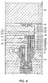
- Figure 4 is a partial sectional view of a portion of multi-layer injection molding apparatus having melt transfer bushings according to a further embodiment of the invention,
- Figure 5 is an isometric view of the melt transfer bushing shown in Figure 3,
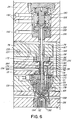
- Figure 6 is a partial sectional view of a portion of multi-layer valve gated injection molding apparatus having melt transfer bushings according to a further embodiment of the invention,
- Figure 7 is an isometric view of the melt transfer bushing shown in Figure 6, and
- Figure 8 is an enlarged sectional view showing the valve pin seen in Figure 5 in the partially open position,
- Figure 9 is a similar view showing the valve pin in the fully open position, and
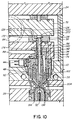
- Figure 10 is a partial sectional view of a portion of multi-layer injection molding apparatus having melt transfer bushings according to a still further embodiment of the invention.
-
- Reference is first made to Figure 1 which shows a portion of multi-cavity sprue gated injection molding apparatus for molding three layer preforms or other products by coinjection molding. A number of heated
nozzles 10 are mounted in amold 12 with arear end 14 abutting against the front face 16 of a front steelmelt distribution manifold 18. While the mold can have a greater number of plates depending upon the application, in this case, only a heatednozzle retainer plate 20, amanifold retainer plate 22 and aback plate 24 secured together bybolts 26, as well as acavity retainer plate 28 are shown for ease of illustration. Thefront end 30 of each heatednozzle 10 is aligned with agate 32 extending through a cooledgate insert 34 to acavity 36. Thiscavity 36 for making beverage bottle preforms extends between acavity insert 38 and amold core 40 in a conventional manner. - Each heated
nozzle 10 is heated by an integral electrical heating element 42 having aterminal 44. Each heatednozzle 10 is seated in an opening 46 in thenozzle retainer plate 20 with arear collar portion 48 of each heatednozzle 10 received in a circular locatingseat 50 extending around the opening 46. This provides aninsulative air space 52 between the heatednozzle 10 and the surroundingmold 12 which is cooled by pumping cooling water throughcooling conduits 54. Eachheated nozzle 10 has acentral melt channel 56 extending from itsrear end 14 to itsfront end 30. Each heatednozzle 10 has aninsert portion 58 made ofseveral pieces 60 which fit together to form an innerannular melt channel 62 extending around thecentral melt channel 56 to thefront end 30 and an outerannular melt channel 64 extending around the innerannular melt channel 62 and thecentral melt channel 56 to thefront end 30. In this configuration, theheated nozzle 10 has asingle melt bore 66 extending from itsrear end 14 to connect to the inner annular melt channel 67 and four spacedmelt bores 68 extending from therear end 14 of theheated nozzle 10 to the outerannular melt channel 64. - The front
melt distribution manifold 18 is heated by an integralelectrical heating element 70. It is located by a central locatingring 72 andscrews 74 extending into each heatednozzle 10 to have aninsulative air space 76 extending between it and the surrounding cooledmold 12. A rear steelmelt distribution manifold 78 is mounted in themold 12 extending parallel to the frontmelt distribution manifold 18 with a number of insulative andresilient spacers 80 extending between it and theback plate 24. As can be seen, the front andrear manifolds spacers 82 to provide aninsulative air space 84 between them. As described in more detail below, the rearmelt distribution manifold 78 is heated by an integralelectrical heating element 86 to a lower operating temperature than the frontmelt distribution manifold 18, and theinsulative air space 84 between them provides sufficient thermal separation to allow this temperature difference to be maintained. - A
first melt passage 88 extends from acentral inlet 90 through acylindrical manifold extension 92 and branches in the frontmelt distribution manifold 18 to extend through amelt dividing bushing 94 seated in the front face 16 of the frontmelt distribution manifold 18 in alignment with each heatednozzle 10. Themelt dividing bushing 94 is made of three steel layers integrally brazed together as described in co-pending Canadian Application Serial No. 2,219,054 entitled, "Injection Molding Apparatus Having Melt Dividing Bushings" filed concurrently herewith. In this configuration, thefirst melt passage 88 divides in themelt dividing bushing 94 to extend to thecentral melt channel 56 and the four spacedmelt bores 68 extending to the outerannular melt channel 64 in the alignedheated nozzle 10. - An elongated
melt transfer bushing 96 according to the invention extends from the rearmelt distribution manifold 78 across theinsulative air space 84 and into abore 98 which extends through the frontmelt distribution manifold 18 and eachmelt dividing bushing 94. While thetransfer bushings 96 can be made of one piece, in this embodiment, as best seen in Figure 2 eachmelt transfer bushing 96 has an elongatedcylindrical body portion 100 with aconnector bushing 102 extending forwardly from it. Theelongated body portion 100 has a threadedrear end 104, afront end 106, a central melt bore 108 extending therethrough from therear end 104 to thefront end 106 and an integralelectrical heating element 110 extending around the central melt bore 108. The threaded rear end of theelongated body portion 100 fits into a threadedseat 112 in the rearmelt distribution manifold 78. Theconnector bushing 102 also has a threaded rear end 114, afront end 116 and a central melt bore 118 extending therethrough which matches the central melt bore 108 through theelongated body portion 100 of themelt transfer bushing 96. The threaded rear end 114 of theconnector bushing 102 fits into a threadedseat 120 at thefront end 106 of theelongated body portion 100 and thefront end 116 of theconnector bushing 102 fits into amatching seat 121 in therear end 14 of theheated nozzle 10. This allows the length of themelt transfer bushing 96 to be adjusted to match the width of theair space 84 between the frontmelt distribution manifold 18 and the rearmelt distribution manifold 78. The diameter of theelongated body portion 100 of themelt transfer bushing 96 is sufficiently smaller than the diameter of thebore 98 through the frontmelt distribution manifold 18 to provide aninsulative air space 124 extending around themelt transfer bushing 96. - A
second melt passage 126 extends from asecond inlet 128 and branches in the rearmelt distribution manifold 78 to extend through the aligned melt bores 108, 118 through eachmelt transfer bushing 96 to the aligned melt bore 66 extending from therear end 14 of eachheated nozzle 10 to the innerannular melt channel 62. While only a singleheated nozzle 10 is shown for ease of illustration, it is understood that in a typical configuration there will be many heated nozzles 10 (eg. 32, 48, or 64) seated in themold 12 to receive melt through the twomelt passages - In use, the injection molding system is assembled as shown in Figure 1 and operates to form three layer preforms or other products with one barrier layer of a material such as EVOH or nylon between two layers of a PET type material as follows. Electrical power is applied to the
heating element 70 in the frontmelt distribution manifold 18 and the heating elements 42 in theheated nozzles 10 to heat them to a temperature of about 565°F. Electrical power is also applied to theheating element 86 in the rearmelt distribution manifold 78 and theheating elements 110 in themelt transfer bushings 96 to heat them to an operating temperature of about 400°F. Water is applied to thecooling conduits 54 to cool themolds 12 and the gate inserts 34. Hot pressurized melt is then injected into thecentral inlet 90 in the frontmelt distribution manifold 18 and thesecond inlet 128 in the rearmelt distribution manifold 78 according to a predetermined injection cycle. First, an injection cylinder (not shown) injects pressurized melt such as a polyethylene terephthalate (PET) type material through thefirst melt passage 88 which splits in eachmelt dividing bushing 94 to extend through both thecentral melt channel 56 and the outerannular melt channel 64 of eachheated nozzle 10 to thegates 32. After a small quantity of PET has been injected into thecavities 36, another pressurized melt which is a suitable barrier material such as ethylene vinyl alcohol copolymer (EVOH) or nylon is then simultaneously coinjected by another injection cylinder (not shown) through thesecond melt passage 126 which extends across theinsulative air space 84 through themelt transfer bushings 96 and through the innerannular melt channel 62 of eachheated nozzle 10 to thegates 32. When thecavities 36 are almost filled, the injection pressure of the barrier material is released which stops its flow, but the flow of PET continues until thecavities 36 are completely filled. Injection pressure of the PET is then released and, after a cooling period, the mold is opened for ejection. After ejection, the mold is closed and the cycle is repeated continuously with a frequency depending upon the wall thickness and number and size ofcavities 36 and the exact type of materials being molded. Thus, as can be seen, in addition to conveying the barrier material across theinsulative air space 84 between the twomanifolds melt transfer bushings 96 provide thermal separation for the barrier material and extra controlled heat if the barrier material is nylon as it flows through the frontmelt distribution manifold 18 which is at a higher temperature. - Reference is now made to Figure 3 showing injection molding apparatus according to another embodiment of the invention. As many of the elements of the various embodiments are the same as described above, not all common elements are described again and those that are described again have the same reference numerals as before. In this case, the
rear end 104 of theelongated body portion 100 of eachmelt transfer bushing 96 is not threaded. Rather, themelt transfer bushing 96 is secured to the rearmelt distribution manifold 78 by screws 130 extending into the rearmelt distribution manifold 78 throughholes 132 in aflange portion 134 of theelongated body portion 100. Otherwise, the structure and use of themelt transfer bushings 96 are the same as described above and need not be repeated. - Reference is now made to Figures 4 and 5 showing injection molding apparatus according to a further embodiment of the invention. In this case, each
melt transfer bushing 96 has a central melt bore 136 extending through arear head portion 138 and anelongated stem portion 140 which extends forwardly from therear head portion 138. Thehead portion 138 of eachmelt transfer bushing 96 forms a spacer to provide theinsulative air space 84 between the front and rearmelt distribution manifolds elongated stem portion 140 extends forwardly through thebore 98 through the frontmelt distribution manifold 18 into contact with therear end 14 of the alignedheated nozzle 10. While themelt transfer bushing 96 can be made of one piece, in the embodiment shown theelongated stem portion 140 has a threadedrear end 142 which is screwed into a threaded seat 144 in thehead portion 138. This allows theelongated stem portion 140 to be made of wear resistant tool steel and therear head portion 138 to be made of a less thermally conductive titanium alloy. As can be seen, therear head portion 138 has a number ofconcentric grooves 146 on both its front and rear faces 148, 150 to reduce thermal conduction from the frontmelt distribution manifold 18 to the lower temperature rearmelt distribution manifold 78. Theelongated stem portion 140 has a smallerouter diameter portion 152 extending between two largerouter diameter portions 154 at its ends which forms theinsulative air space 124 around themelt transfer bushing 96 as it extends through thebore 98 in the frontmelt distribution manifold 18. As mentioned above, thisinsulative air space 124 provides thermal separation for the barrier material as it flows through the frontmelt distribution manifold 18 which is at a higher temperature. - Reference is now made to Figures 6 to 9 showing injection molding apparatus according to a different embodiment of the invention for molding three layer preforms or other products by simultaneous or coinjection molding. In this case, the apparatus has
valve gates 32 provided by elongated valve pins 156 which extend through thecentral bore 136 through eachmelt transfer bushing 96 and the alignedcentral melt channel 56 in eachheated nozzle 10. Eachvalve pin 156 has afront end 158 and a rear end orhead 159. As best seen in Figures 8 and 9, eachvalve pin 156 has acentral bore 160 extending rearwardly from itsfront end 158 to four lateral melt bores 161 which extend diagonally outward to theouter surface 162 of thevalve pin 156. In this embodiment, eachvalve pin 156 has a reduceddiameter portion 163 which fits in a reduceddiameter portion 164 of thecentral melt channel 56 through theheated nozzle 10. The reduceddiameter portion 163 of thevalve pin 156 is longer than the reduceddiameter portion 164 of thecentral melt channel 56 which thus forms aspace 165 around the reduceddiameter portion 163 of thevalve pin 156. As described below, the elongated valve pins 156 are reciprocated byhydraulic actuating mechanism 166 according to a predetermined cycle between three different positions In this embodiment, eachmelt transfer bushing 96 also has acylindrical neck portion 167 which extends rearwardly into anopening 168 through the rearmelt distribution manifold 78, and thecentral bore 136 extends through thisrear neck portion 167 as well. - As can be seen, in this embodiment, the
insert portion 58 of eachheated nozzle 10 only forms a singleannular melt channel 169 extending around thecentral melt channel 56 with four spaced melt bores 170 extending rearwardly from theannular melt channel 169 to therear end 14 of theheated nozzle 10. Thefirst melt passage 88 for the PET divides in themelt dividing bushing 94 to extend to the four melt bores 170 leading to theannular melt channel 169 in the alignedheated nozzle 10. Thesecond melt passage 126 for the barrier material branches in the rearmelt distribution manifold 78 and extends through an L-shapedpassage 172 drilled in thehead portion 138 of eachmelt transfer bushing 96 to alongitudinal groove 174 machined to extend a predetermined distance rearwardly in thevalve pin 156 from thespace 165 around the reduceddiameter portion 163 of thevalve pin 156. In other embodiments, thegroove 174 can extend helically around thevalve pin 156 or thevalve pin 156 can be small enough to let the barrier material flow around it. However, in view of the relatively low volume and low viscosity of the barrier material, it is preferable to have it flow through thegroove 174. Thevalve pin 156 fits in thecentral bore 136 in themelt transfer bushing 96 tightly enough to prevent melt leakage as theelongated valve pin 156 reciprocates. Eachmelt transfer bushing 96 is retained in proper alignment by a small dowel 176 which extends between it and the frontmelt distribution manifold 18. Theinsert portion 58 of eachheated nozzle 10 also has an annularinsulative air space 178 extending between thecentral melt channel 56 and the surroundingannular melt channel 168 to provide some thermal separation between them. Further thermal separation is provided around thecentral melt channel 56 by a circle of spacedholes 180 drilled in therear end 14 of eachheated nozzle 10. Combined with theinsulative air space 124 around thestem portion 140 of eachmelt transfer bushing 96, this provides continuous thermal separation for the barrier material as it flows through the higher temperature frontmelt distribution manifold 18 and theheated nozzles 10. Thefront face 148 of thehead portion 138 of eachmelt transfer bushing 96 has anouter rim 182 which forms aninsulative air space 184 between thehead portion 138 and the frontmelt distribution manifold 18 to provide thermal separation between the front and rearmelt distribution manifolds - The rear end or
head 159 of thevalve pin 156 is connected to afront piston 186 seated in acylinder 188 in the back orcylinder plate 24. Theactuating mechanism 166 also includes arear piston 190, and the twopistons ducts 192 to reciprocate thevalve pin 156 between three different positions. Whilehydraulic actuating mechanisms 166 are shown for ease of illustration, of course, other types of actuating mechanisms such as electro-mechanical mechanisms can be used for other applications. - In use, each
valve pin 156 is initially retracted only far enough to a first partially open position to allow PET to flow through theannular melt channel 169. In this embodiment, there is a double blockage of the barrier material flow in this middle position. As seen in Figure 8, the lateral melt bores 161 in thevalve pin 156 are too far forward to connect with thespace 165 around the reduceddiameter portion 163 of thevalve pin 156. Furthermore, as seen in Figure 6, the longitudinal orhelical groove 174 in thevalve pin 156 does not extend far enough rearwardly to connect with the L-shapedpassage 172 in themelt transfer bushing 96 in this position. In other embodiments, it may only be necessary to use one or the other of these ways of blocking the flow of the barrier material. - Then, each
valve pin 156 is retracted further to a second or open position shown in Figure 9. In this position, the lateral melt bores 161 in thevalve pin 156 are connected with thespace 165 around the reduceddiameter portion 163 of eachvalve pin 156 and thelongitudinal groove 174 in thevalve pin 156 does connect with the L-shapedpassage 172 in themelt transfer bushing 96 which allows the barrier material to flow through themelt passage 126 into thecavities 36. As mentioned above, the central location of thebore 160 at thefront end 158 of thevalve pin 156 and the relatively small size of thegroove 174 and thecentral bore 160 combine with the relatively low volume and low viscosity of the barrier material to ensure that the flow of the barrier material is reliable to provide a uniform and very thin layer of the barrier material which is quite expensive. As seen in Figure 9, the barrier material flowing simultaneously with the PET splits the PET flow in two and provides acentral layer 194 of the barrier material between twoouter layers 196 of PET. - When the
cavities 36 are almost filled, the front end of eachvalve member 156 is returned to the first position closing off the flow of the barrier material through thecentral bore 160. The flow of PET through theannular melt channel 169 continues untilcavities 36 are completely filled. Eachvalve pin 156 is then driven to the third or forward closed position in which itsfront end 158 is seated in thegate 32 flush with thecavity 36. After a short cooling period, the mold is opened for ejection. After ejection, the mold is closed and the cycle is repeated continuously every 15 to 30 seconds with a frequency depending upon the wall thickness and number and size ofcavities 36 and the exact materials being molded. - Reference is now made to Figure 10 showing injection molding apparatus according to another embodiment of the invention. In this case, each
melt transfer bushing 96 again has thecentral bore 136 extending through anelongated stem portion 140 and arear head portion 138 which forms a spacer between the twomelt distribution manifolds elongated pin 198 is fixed in place with itshead 200 seated in therear face 202 of thehead portion 138 of eachmelt transfer bushing 96 and its partially taperedfront end 204 adjacent to and in alignment with one of thegates 32. Although not seen in Figure 10 because of the scale of the drawing, the elongated pin has acentral bore 160 extending to itsfront end 204 andlateral bores 161 the same as seen in Figure 9. During each cycle, PET is first injected through thefirst melt passage 88 and flows through theannular melt channel 168 in eachheated nozzle 10 to thegates 32 leading to thecavities 36. A short time after the start of PET injection, a predetermined quantity of the less viscose barrier material is then simultaneously injected through thesecond melt passage 126 which forms acentral layer 194 of the barrier material between two outer PET layers 196. When thecavities 36 are almost filled, the injection pressure of the barrier material is released which stops its flow and the PET injection is continued to completely fill thecavities 36. Injection pressure of the PET is then released and, after a short cooling period, the mold is opened for ejection. After ejection, themold 12 is closed and the cycle is repeated continuously every 15 to 30 seconds with a frequency depending upon the wall thickness and number and size of thecavities 36 and the exact materials being molded. - While the description of the injection molding apparatus having melt transfer bushings extending across the
air space 84 between the front and rearmelt distribution manifolds
Claims (24)
- In a multi-cavity hot runner injection molding apparatus for multi-layer molding having a front melt distribution manifold and a rear melt distribution manifold mounted in a mold extending substantially parallel to each other with an insulative air space therebetween, a plurality of heated nozzles, each heated nozzle having a rear end, a front end, a central melt channel extending therethrough from the rear end to the front end, an inner annular melt channel extending to the front end around the central melt channel with a first melt bore extending from the rear end of the heated nozzle to the inner annular melt channel and an outer annular melt channel extending to the front end around the central melt channel and the inner annular melt channel with at least one second melt bore extending from the rear end of the heated nozzle to the outer annular melt channel, the heated nozzles being mounted in the mold with the rear end of each heated nozzle abutting against the front melt distribution manifold, a first melt passage from a first melt source branching in the front melt distribution manifold and dividing again to extend through the central melt channel and the at least one second melt bore extending from the rear end of the heated nozzle to the outer annular melt channel and the outer annular melt channel in each heated nozzle to a gate adjacent the front end of the heated nozzle leading to a cavity in the mold, and a second melt passage from a second melt source branching in the rear melt distribution manifold and extending through the first melt bore and the inner annular melt channel in each heated nozzle to the gate, the improvement further comprising;a plurality of melt transfer bushings, each melt transfer bushing having a rear end, a front end, and a central melt bore extending therethrough from the rear end to the front end, each melt transfer bushing being mounted in a position to extend from the rear melt distribution manifold forwardly across the insulative air space between the rear melt distribution manifold and the front melt distribution manifold and into a bore extending through the front melt distribution manifold to the first melt bore extending from the rear end of one of the heated nozzles to the inner annular melt channel, whereby the central bore through each melt transfer bushing forms a part of the second melt passage.
- Injection molding apparatus as claimed in claim 1 wherein each melt transfer bushing extends through the bore through the front melt distribution manifold into sealing contact with the rear end of said one of the heated nozzles.
- Injection molding apparatus as claimed in claim 2 wherein there is an insulative air gap between each melt transfer bushing and the surrounding front melt distribution manifold.
- Injection molding apparatus as claimed in claim 3 wherein each melt transfer bushing has an integral electrical heating element, the electrical heating element having a helical portion extending around at least part of the central melt bore extending through the melt transfer bushing.
- Injection molding apparatus as claimed in claim 2 wherein each melt transfer bushing comprises an elongated body portion and a connector bushing, the elongated body portion having a rear end, a front end, and a central melt bore extending therethrough from the rear end to the front end, the connector bushing having a rear end, a front end, and a central melt bore extending therethrough which matches the central melt bore extending through the elongated body portion, the connector bushing extending forwardly from the elongated body portion.
- Injection molding apparatus as claimed in claim 5 wherein the rear end of the elongated body portion of each melt transfer bushing is threaded to screw into a threaded seat extending around the second melt passage in the rear melt distribution manifold.
- Injection molding apparatus as claimed in claim 6 wherein one of the central melt bore at the front end of the elongated body portion of each melt transfer bushing and the first melt bore extending from the rear end of the aligned heated nozzle has a threaded seat therearound and one of the front and rear ends of the connector bushing is threaded, the threaded end of the connector bushing being screwed into said threaded seat in one of the central melt bore at the front end of the elongated body portion of each melt transfer bushing and the first melt bore extending from the rear end of the heated nozzle.
- Injection molding apparatus as claimed in claim 2 wherein each melt transfer bushing has a head portion and an elongated stem portion, the head portion extending between the rear melt distribution manifold and the front melt distribution manifold to be a spacer to provide the insulative air space therebetween, the elongated stem portion extending from the head portion forwardly through the bore extending through the front melt distribution manifold.
- In a multi-cavity hot runner injection molding apparatus for multi-layer molding having a front melt distribution manifold and a rear melt distribution manifold mounted in a mold extending substantially parallel to each other with an insulative air space therebetween, a plurality of heated nozzles, each heated nozzle having a rear end, a front end, a central melt channel extending therethrough from the rear end to the front end and an annular melt channel extending around the central melt channel to the front end with at least one melt bore extending from the rear end of the heated nozzle to the annular melt channel, the heated nozzles being mounted in the mold with the rear end of each heated nozzle abutting against the front melt distribution manifold, a first melt passage from a first melt source branching in the front melt distribution manifold and extending through the at least one melt bore and the annular melt channel in each heated nozzle to a gate adjacent the front end of the heated nozzle leading to a cavity in the mold, and a second melt passage from a second melt source branching in the rear melt distribution manifold and extending through the central melt channel in each heated nozzle to the gate, the improvement further comprising;a plurality of melt transfer bushings, each melt transfer bushing having a head portion at a rear end, an elongated stem portion extending from the head portion forwardly to a front end and a central bore extending therethrough from the rear end to the front end, each melt transfer bushing being mounted in alignment with the central melt channel of one of the heated nozzles, the head portion extending between the rear melt distribution manifold and the front melt distribution manifold to be a spacer to provide the insulative air space therebetween, the elongated stem portion extending from the head portion forwardly into a bore extending through the front melt distribution manifold in alignment with the central melt channel through the aligned heated nozzle, whereby the central bore through each melt transfer bushing receives an elongated pin which extends forwardly therefrom into the central melt channel in the aligned heated nozzle with the second melt passage from the second melt source extending along the elongated pin.
- Injection molding apparatus as claimed in claim 9 wherein the elongated stem portion of each melt transfer bushing extends through the bore through the front melt distribution manifold with the front end of each melt transfer bushing abutting against the rear end of the aligned heated nozzle.
- Injection molding apparatus as claimed in claim 10 wherein there is an insulative air gap between the elongated stem portion of each melt transfer bushing and the surrounding front melt distribution manifold.
- Injection molding apparatus as claimed in claim 11 wherein the head portion of each melt transfer bushing has an off-center melt channel extending from an inlet on the rear end to join the central melt channel and form part of the second melt passage.
- Injection molding apparatus as claimed in claim 12 wherein the off-center melt passage is L-shaped.
- Injection molding apparatus as claimed in claim 12 wherein the elongated pin is a valve pin and further including actuating mechanism to reciprocate the valve member between a retracted open position and a forward closed position.
- Injection molding apparatus as claimed in claim 14 wherein each melt transfer bushing further comprises a neck portion extending rearwardly from the head portion into an opening in the rear melt distribution manifold and the elongated valve pin fits in the central bore in the neck portion tightly enough to prevent melt leakage as the elongated valve pin reciprocates.
- Injection molding apparatus as claimed in claim 12 wherein the elongated pin is a fixed pin with a longitudinally extending melt groove therein.
- The injection molding apparatus as claimed in claim 1 wherein there is an insulative air space between each heated nozzle and the surrounding mold.
- The injection molding apparatus as claimed in claim 1 wherein the insulative air space between the rear melt distribution manifold and the front melt distribution manifold is formed by positioning a plurality of spacers therebetween.
- The injection molding apparatus as claimed in claim 1 wherein there is an insulative air space between the front melt distribution manifold and the surrounding cooled mold.
- The injection molding apparatus as claimed in claim 19 wherein the insulative air space between the front melt distribution manifold and the surrounding cooled mold is formed by positioning a central locating ring therebetween.
- The injection molding apparatus as claimed in claim 1 wherein there is an insulative air space located between the rear melt distribution manifold and a back plate.
- The injection molding apparatus as claimed in claim 19 wherein there is an insulative air space located between the rear melt distribution manifold and a back plate.
- The injection molding apparatus as claimed in claim 22 wherein there is an insulative air space between each heated nozzle and the surrounding mold.
- The injection molding apparatus as claimed in claim 1 wherein said insulative air spaces provide sufficient thermal separation to allow a temperature difference to be maintained between a first melt passing through the rear melt distribution manifold and a second melt passing through the front distribution manifold as said melts pass into said nozzles.
Applications Claiming Priority (3)
| Application Number | Priority Date | Filing Date | Title |
|---|---|---|---|
| CA002219260A CA2219260C (en) | 1997-10-23 | 1997-10-23 | Injection molding apparatus having inter-manifold melt transfer bushings |
| CA2219260 | 1997-10-23 | ||
| US08/969,756 US5935616A (en) | 1997-10-23 | 1997-11-13 | Injection molding apparatus having inter-manifold melt transfer bushings |
Publications (2)
| Publication Number | Publication Date |
|---|---|
| EP0911138A1 true EP0911138A1 (en) | 1999-04-28 |
| EP0911138B1 EP0911138B1 (en) | 2002-07-31 |
Family
ID=25679766
Family Applications (1)
| Application Number | Title | Priority Date | Filing Date |
|---|---|---|---|
| EP98120039A Expired - Lifetime EP0911138B1 (en) | 1997-10-23 | 1998-10-22 | Injection molding apparatus having inter-manifold melt transfer bushings |
Country Status (6)
| Country | Link |
|---|---|
| US (1) | US5935616A (en) |
| EP (1) | EP0911138B1 (en) |
| JP (1) | JPH11198189A (en) |
| CN (1) | CN1099952C (en) |
| CA (1) | CA2219260C (en) |
| DE (1) | DE19848817A1 (en) |
Cited By (5)
| Publication number | Priority date | Publication date | Assignee | Title |
|---|---|---|---|---|
| WO2001034365A1 (en) * | 1999-11-08 | 2001-05-17 | Husky Injection Molding Systems Ltd. | Improved mixer apparatus and method for injection molding machines |
| WO2001064419A1 (en) * | 2000-02-29 | 2001-09-07 | Bemis Manufacturing Company | Co-injection apparatus for injection molding |
| US6349886B1 (en) | 1999-11-08 | 2002-02-26 | Husky Injection Molding Systems Ltd. | Injector nozzle and method |
| WO2002078929A1 (en) * | 2001-03-30 | 2002-10-10 | Husky Injection Molding Systems Ltd. | Melt flow mixer in a shot runner |
| US6964748B2 (en) | 2000-11-30 | 2005-11-15 | Bemis Manufacturing Company | Co-injection methods using endothermic-blowing agents and products made therefrom |
Families Citing this family (21)
| Publication number | Priority date | Publication date | Assignee | Title |
|---|---|---|---|---|
| CA2219235C (en) * | 1997-10-23 | 2006-12-12 | Mold-Masters Limited | Five layer injection molding apparatus having four position valve member actuating mechanism |
| CA2219257C (en) * | 1997-10-23 | 2005-05-31 | Mold-Masters Limited | Sprue gated five layer injection molding apparatus |
| US6101791A (en) * | 1998-04-03 | 2000-08-15 | Louviere; Kent A. | Method of making a plurality of interconnected vials |
| CA2248553A1 (en) * | 1998-09-30 | 2000-03-30 | Jobst Ulrich Gellert | Injection molding nozzle screwed into mounting base |
| WO2004060631A1 (en) * | 2003-01-03 | 2004-07-22 | Xingyuan Zhu | Method and apparatus for injection molding a plastic diaphragm of filter press |
| US7862760B2 (en) * | 2003-03-07 | 2011-01-04 | Acushnet Company | Co-injection nozzle, method of its use, and resulting golf ball |
| US7261535B2 (en) * | 2003-12-31 | 2007-08-28 | Acushnet Company | Co-injection nozzle |
| DE102005049605A1 (en) * | 2004-10-19 | 2006-04-20 | Mold-Masters Ltd., Georgetown | Manifold plug for hot runner injection system lies between back plate and tool plate, fits in manifold bore, has channel linking manifold and nozzle melt channels and integral pressure disc pressed against back plate |
| JP4266019B2 (en) * | 2005-08-30 | 2009-05-20 | 本田技研工業株式会社 | Injection mold hot runner mold color changing device |
| US20070292558A1 (en) * | 2006-06-14 | 2007-12-20 | Husky Injection Molding Systems Ltd. | Rail and pillar hot runner |
| US7517214B2 (en) * | 2007-05-24 | 2009-04-14 | Mold-Masters (2007) Limited | Valve pin bushing having a thermally insulative component |
| US7845936B2 (en) * | 2009-01-21 | 2010-12-07 | Mold-Masters (2007) Limited | Sealing arrangement for an edge gated nozzle in an injection molding system |
| CN101708649B (en) * | 2009-08-13 | 2012-11-21 | 深圳市安高模具有限公司 | Layered hot runner mold |
| KR101031146B1 (en) | 2010-09-20 | 2011-04-27 | 허남욱 | Hot runner injection molding having a device for self-centering of nozzle |
| US9498911B2 (en) | 2010-09-21 | 2016-11-22 | Mold-Masters (2007) Limited | Coinjection hot runner injection molding system |
| WO2012037682A2 (en) | 2010-09-21 | 2012-03-29 | Mold-Masters (2007) Limited | Coinjection hot runner injection molding system |
| BE1022045B1 (en) * | 2011-02-03 | 2016-02-09 | Resilux | Injection molding device for the manufacture of hollow articles, I.H.B. PLASTIC PREPARATIONS, RESP.-CONTAINERS, AND METHOD FOR THIS |
| US9073246B2 (en) | 2011-09-21 | 2015-07-07 | Mold-Masters (2007) Limited | Coinjection hot runner injection molding system |
| JP2013220542A (en) * | 2012-04-13 | 2013-10-28 | Olympus Corp | Injection mold |
| CN112643980A (en) * | 2020-12-14 | 2021-04-13 | 台州市黄岩炜大塑料机械有限公司 | PVC material heat insulation runner of injection mold |
| CN114919123B (en) * | 2022-03-09 | 2023-11-03 | 上海珂明注塑系统科技有限公司 | Injection molding device |
Citations (5)
| Publication number | Priority date | Publication date | Assignee | Title |
|---|---|---|---|---|
| US4433969A (en) * | 1982-07-12 | 1984-02-28 | Gellert Jobst U | Injection molding valve pin bushing and method |
| EP0467274A2 (en) * | 1990-07-16 | 1992-01-22 | Nissei Asb Machine Co., Ltd. | Multi-ply molding hot-runner mold |
| EP0579925A1 (en) * | 1992-06-23 | 1994-01-26 | COMMER S.p.A. | A device for the co-injection in different points of a mold |
| EP0790116A2 (en) * | 1996-02-19 | 1997-08-20 | Fried. Krupp AG Hoesch-Krupp | Method for injection moulding three-layered moulded objects and apparatus for carrying out the method |
| EP0799683A2 (en) * | 1996-04-04 | 1997-10-08 | Fried. Krupp AG Hoesch-Krupp | Method for injection molding of three-layered products and device for conducting said method |
Family Cites Families (2)
| Publication number | Priority date | Publication date | Assignee | Title |
|---|---|---|---|---|
| US5223275A (en) * | 1990-10-12 | 1993-06-29 | Gellert Jobst U | Multi-cavity injection moulding system |
| JP2667594B2 (en) * | 1991-04-15 | 1997-10-27 | 株式会社日本製鋼所 | Injection molding method and injection molding die |
-
1997
- 1997-10-23 CA CA002219260A patent/CA2219260C/en not_active Expired - Fee Related
- 1997-11-13 US US08/969,756 patent/US5935616A/en not_active Expired - Lifetime
-
1998
- 1998-10-22 EP EP98120039A patent/EP0911138B1/en not_active Expired - Lifetime
- 1998-10-22 DE DE19848817A patent/DE19848817A1/en not_active Withdrawn
- 1998-10-23 CN CN98120187A patent/CN1099952C/en not_active Expired - Lifetime
- 1998-10-23 JP JP10302651A patent/JPH11198189A/en active Pending
Patent Citations (5)
| Publication number | Priority date | Publication date | Assignee | Title |
|---|---|---|---|---|
| US4433969A (en) * | 1982-07-12 | 1984-02-28 | Gellert Jobst U | Injection molding valve pin bushing and method |
| EP0467274A2 (en) * | 1990-07-16 | 1992-01-22 | Nissei Asb Machine Co., Ltd. | Multi-ply molding hot-runner mold |
| EP0579925A1 (en) * | 1992-06-23 | 1994-01-26 | COMMER S.p.A. | A device for the co-injection in different points of a mold |
| EP0790116A2 (en) * | 1996-02-19 | 1997-08-20 | Fried. Krupp AG Hoesch-Krupp | Method for injection moulding three-layered moulded objects and apparatus for carrying out the method |
| EP0799683A2 (en) * | 1996-04-04 | 1997-10-08 | Fried. Krupp AG Hoesch-Krupp | Method for injection molding of three-layered products and device for conducting said method |
Non-Patent Citations (1)
| Title |
|---|
| GOLDBACH H: "HEISSKANAL-WERKZEUGE FUER DIE VERARBEITUNG "TECHNISCHER" THERMOPLASTE (WIE ABS, PA, PBT, PC)", PLASTVERARBEITER, vol. 29, no. 12, December 1978 (1978-12-01), pages 677 - 682, XP002054208 * |
Cited By (6)
| Publication number | Priority date | Publication date | Assignee | Title |
|---|---|---|---|---|
| WO2001034365A1 (en) * | 1999-11-08 | 2001-05-17 | Husky Injection Molding Systems Ltd. | Improved mixer apparatus and method for injection molding machines |
| US6349886B1 (en) | 1999-11-08 | 2002-02-26 | Husky Injection Molding Systems Ltd. | Injector nozzle and method |
| WO2001064419A1 (en) * | 2000-02-29 | 2001-09-07 | Bemis Manufacturing Company | Co-injection apparatus for injection molding |
| US6974556B2 (en) | 2000-02-29 | 2005-12-13 | Bemis Manufacturing Company | Co-injection apparatus for injection molding |
| US6964748B2 (en) | 2000-11-30 | 2005-11-15 | Bemis Manufacturing Company | Co-injection methods using endothermic-blowing agents and products made therefrom |
| WO2002078929A1 (en) * | 2001-03-30 | 2002-10-10 | Husky Injection Molding Systems Ltd. | Melt flow mixer in a shot runner |
Also Published As
| Publication number | Publication date |
|---|---|
| CA2219260A1 (en) | 1999-04-23 |
| CN1099952C (en) | 2003-01-29 |
| US5935616A (en) | 1999-08-10 |
| JPH11198189A (en) | 1999-07-27 |
| CA2219260C (en) | 2006-12-05 |
| DE19848817A1 (en) | 1999-04-29 |
| CN1215658A (en) | 1999-05-05 |
| EP0911138B1 (en) | 2002-07-31 |
Similar Documents
| Publication | Publication Date | Title |
|---|---|---|
| US5935616A (en) | Injection molding apparatus having inter-manifold melt transfer bushings | |
| EP0911135B1 (en) | Injection molding apparatus having a melt bore through the front end of the pin | |
| US6274075B1 (en) | Five layer injection molding apparatus having four position valve member actuating mechanism | |
| CA2253042C (en) | Method of three layer injection molding with sequential and simultaneous coinjection | |
| US6062841A (en) | Sprue gated multi-layer injection molding apparatus | |
| US6113381A (en) | Injection molding valve member actuating mechanism | |
| EP0916468B1 (en) | Injection molding apparatus having melt transfer and dividing bushing | |
| US6135751A (en) | Injection molding apparatus having melt dividing bushings | |
| US5942257A (en) | Multi-layer injection molding apparatus having three position valve member | |
| MXPA98008713A (en) | Injection molding apparatus that has transfer bushings of bath fused between multip | |
| MXPA98008711A (en) | Molding apparatus for five layer injection with a four position valve member activation mechanism | |
| MXPA98008716A (en) | Injection molding apparatus with injection hole for multip five layer molding | |
| MXPA99000290A (en) | Molding apparatus by injection of multiple layers that has a three-position valve member | |
| MXPA99002251A (en) | Mechanism of actuation of valve member for molding by inyecc | |
| MXPA98008712A (en) | Injection molded apparatus with transfer bushing and division of material fund | |
| MXPA98008714A (en) | Injection molding device that has barrenode bath flooded through the front end of the ag |
Legal Events
| Date | Code | Title | Description |
|---|---|---|---|
| PUAI | Public reference made under article 153(3) epc to a published international application that has entered the european phase |
Free format text: ORIGINAL CODE: 0009012 |
|
| AK | Designated contracting states |
Kind code of ref document: A1 Designated state(s): AT BE CH CY DE DK ES FI FR GB IE IT LI LU NL PT SE |
|
| AX | Request for extension of the european patent |
Free format text: AL;LT;LV;MK;RO;SI |
|
| 17P | Request for examination filed |
Effective date: 19991011 |
|
| AKX | Designation fees paid |
Free format text: AT BE CH CY DE DK ES FI FR GB IE IT LI LU NL PT SE |
|
| 17Q | First examination report despatched |
Effective date: 20000920 |
|
| GRAG | Despatch of communication of intention to grant |
Free format text: ORIGINAL CODE: EPIDOS AGRA |
|
| GRAG | Despatch of communication of intention to grant |
Free format text: ORIGINAL CODE: EPIDOS AGRA |
|
| GRAH | Despatch of communication of intention to grant a patent |
Free format text: ORIGINAL CODE: EPIDOS IGRA |
|
| GRAH | Despatch of communication of intention to grant a patent |
Free format text: ORIGINAL CODE: EPIDOS IGRA |
|
| GRAA | (expected) grant |
Free format text: ORIGINAL CODE: 0009210 |
|
| AK | Designated contracting states |
Kind code of ref document: B1 Designated state(s): AT BE CH CY DE DK ES FI FR GB IE IT LI LU NL PT SE |
|
| PG25 | Lapsed in a contracting state [announced via postgrant information from national office to epo] |
Ref country code: FR Free format text: LAPSE BECAUSE OF FAILURE TO SUBMIT A TRANSLATION OF THE DESCRIPTION OR TO PAY THE FEE WITHIN THE PRESCRIBED TIME-LIMIT Effective date: 20020731 Ref country code: FI Free format text: LAPSE BECAUSE OF FAILURE TO SUBMIT A TRANSLATION OF THE DESCRIPTION OR TO PAY THE FEE WITHIN THE PRESCRIBED TIME-LIMIT Effective date: 20020731 Ref country code: BE Free format text: LAPSE BECAUSE OF FAILURE TO SUBMIT A TRANSLATION OF THE DESCRIPTION OR TO PAY THE FEE WITHIN THE PRESCRIBED TIME-LIMIT Effective date: 20020731 Ref country code: AT Free format text: LAPSE BECAUSE OF FAILURE TO SUBMIT A TRANSLATION OF THE DESCRIPTION OR TO PAY THE FEE WITHIN THE PRESCRIBED TIME-LIMIT Effective date: 20020731 |
|
| REF | Corresponds to: |
Ref document number: 221445 Country of ref document: AT Date of ref document: 20020815 Kind code of ref document: T |
|
| REG | Reference to a national code |
Ref country code: GB Ref legal event code: FG4D Ref country code: CH Ref legal event code: EP |
|
| REG | Reference to a national code |
Ref country code: CH Ref legal event code: NV Representative=s name: PATENTANWALTSBUERO JEAN HUNZIKER |
|
| REG | Reference to a national code |
Ref country code: IE Ref legal event code: FG4D |
|
| REF | Corresponds to: |
Ref document number: 69806881 Country of ref document: DE Date of ref document: 20020905 |
|
| PG25 | Lapsed in a contracting state [announced via postgrant information from national office to epo] |
Ref country code: IE Free format text: LAPSE BECAUSE OF NON-PAYMENT OF DUE FEES Effective date: 20021022 |
|
| PG25 | Lapsed in a contracting state [announced via postgrant information from national office to epo] |
Ref country code: SE Free format text: LAPSE BECAUSE OF FAILURE TO SUBMIT A TRANSLATION OF THE DESCRIPTION OR TO PAY THE FEE WITHIN THE PRESCRIBED TIME-LIMIT Effective date: 20021031 Ref country code: GB Free format text: LAPSE BECAUSE OF NON-PAYMENT OF DUE FEES Effective date: 20021031 Ref country code: DK Free format text: LAPSE BECAUSE OF FAILURE TO SUBMIT A TRANSLATION OF THE DESCRIPTION OR TO PAY THE FEE WITHIN THE PRESCRIBED TIME-LIMIT Effective date: 20021031 Ref country code: CY Free format text: LAPSE BECAUSE OF FAILURE TO SUBMIT A TRANSLATION OF THE DESCRIPTION OR TO PAY THE FEE WITHIN THE PRESCRIBED TIME-LIMIT Effective date: 20021031 |
|
| PG25 | Lapsed in a contracting state [announced via postgrant information from national office to epo] |
Ref country code: PT Free format text: LAPSE BECAUSE OF FAILURE TO SUBMIT A TRANSLATION OF THE DESCRIPTION OR TO PAY THE FEE WITHIN THE PRESCRIBED TIME-LIMIT Effective date: 20021114 |
|
| PG25 | Lapsed in a contracting state [announced via postgrant information from national office to epo] |
Ref country code: ES Free format text: LAPSE BECAUSE OF FAILURE TO SUBMIT A TRANSLATION OF THE DESCRIPTION OR TO PAY THE FEE WITHIN THE PRESCRIBED TIME-LIMIT Effective date: 20030130 |
|
| PLBE | No opposition filed within time limit |
Free format text: ORIGINAL CODE: 0009261 |
|
| STAA | Information on the status of an ep patent application or granted ep patent |
Free format text: STATUS: NO OPPOSITION FILED WITHIN TIME LIMIT |
|
| GBPC | Gb: european patent ceased through non-payment of renewal fee | ||
| 26N | No opposition filed |
Effective date: 20030506 |
|
| REG | Reference to a national code |
Ref country code: IE Ref legal event code: MM4A |
|
| REG | Reference to a national code |
Ref country code: CH Ref legal event code: PUE Owner name: MOLD-MASTERS (2007) LIMITED Free format text: MOLD-MASTERS LIMITED#233 ARMSTRONG AVENUE#GEORGETOWN ONTARIO L7G 4X5 (CA) -TRANSFER TO- MOLD-MASTERS (2007) LIMITED#233 ARMSTRONG AVE.#GEORGETOWN, ONTARIO L7G 4X5 (CA) |
|
| NLS | Nl: assignments of ep-patents |
Owner name: MOLD-MASTERS (2007) LIMITED Effective date: 20080530 |
|
| PGFP | Annual fee paid to national office [announced via postgrant information from national office to epo] |
Ref country code: LU Payment date: 20080929 Year of fee payment: 11 Ref country code: CH Payment date: 20080926 Year of fee payment: 11 |
|
| PGFP | Annual fee paid to national office [announced via postgrant information from national office to epo] |
Ref country code: NL Payment date: 20080926 Year of fee payment: 11 |
|
| PGFP | Annual fee paid to national office [announced via postgrant information from national office to epo] |
Ref country code: IT Payment date: 20081016 Year of fee payment: 11 |
|
| REG | Reference to a national code |
Ref country code: NL Ref legal event code: V1 Effective date: 20100501 |
|
| REG | Reference to a national code |
Ref country code: CH Ref legal event code: PL |
|
| PG25 | Lapsed in a contracting state [announced via postgrant information from national office to epo] |
Ref country code: NL Free format text: LAPSE BECAUSE OF NON-PAYMENT OF DUE FEES Effective date: 20100501 |
|
| PG25 | Lapsed in a contracting state [announced via postgrant information from national office to epo] |
Ref country code: LI Free format text: LAPSE BECAUSE OF NON-PAYMENT OF DUE FEES Effective date: 20091031 Ref country code: CH Free format text: LAPSE BECAUSE OF NON-PAYMENT OF DUE FEES Effective date: 20091031 |
|
| PG25 | Lapsed in a contracting state [announced via postgrant information from national office to epo] |
Ref country code: IT Free format text: LAPSE BECAUSE OF NON-PAYMENT OF DUE FEES Effective date: 20091022 |
|
| PG25 | Lapsed in a contracting state [announced via postgrant information from national office to epo] |
Ref country code: LU Free format text: LAPSE BECAUSE OF NON-PAYMENT OF DUE FEES Effective date: 20091022 |
|
| PGFP | Annual fee paid to national office [announced via postgrant information from national office to epo] |
Ref country code: DE Payment date: 20170920 Year of fee payment: 20 |
|
| REG | Reference to a national code |
Ref country code: DE Ref legal event code: R071 Ref document number: 69806881 Country of ref document: DE |