EP0910284B1 - Optical biopsy forceps - Google Patents
Optical biopsy forceps Download PDFInfo
- Publication number
- EP0910284B1 EP0910284B1 EP97922685A EP97922685A EP0910284B1 EP 0910284 B1 EP0910284 B1 EP 0910284B1 EP 97922685 A EP97922685 A EP 97922685A EP 97922685 A EP97922685 A EP 97922685A EP 0910284 B1 EP0910284 B1 EP 0910284B1
- Authority
- EP
- European Patent Office
- Prior art keywords
- jaws
- optical
- tubular member
- optical fiber
- forceps
- Prior art date
- Legal status (The legal status is an assumption and is not a legal conclusion. Google has not performed a legal analysis and makes no representation as to the accuracy of the status listed.)
- Expired - Lifetime
Links
Images


Classifications
-
- A—HUMAN NECESSITIES
- A61—MEDICAL OR VETERINARY SCIENCE; HYGIENE
- A61B—DIAGNOSIS; SURGERY; IDENTIFICATION
- A61B10/00—Other methods or instruments for diagnosis, e.g. instruments for taking a cell sample, for biopsy, for vaccination diagnosis; Sex determination; Ovulation-period determination; Throat striking implements
- A61B10/02—Instruments for taking cell samples or for biopsy
- A61B10/06—Biopsy forceps, e.g. with cup-shaped jaws
-
- A—HUMAN NECESSITIES
- A61—MEDICAL OR VETERINARY SCIENCE; HYGIENE
- A61B—DIAGNOSIS; SURGERY; IDENTIFICATION
- A61B90/00—Instruments, implements or accessories specially adapted for surgery or diagnosis and not covered by any of the groups A61B1/00 - A61B50/00, e.g. for luxation treatment or for protecting wound edges
- A61B90/30—Devices for illuminating a surgical field, the devices having an interrelation with other surgical devices or with a surgical procedure
- A61B2090/306—Devices for illuminating a surgical field, the devices having an interrelation with other surgical devices or with a surgical procedure using optical fibres
-
- A—HUMAN NECESSITIES
- A61—MEDICAL OR VETERINARY SCIENCE; HYGIENE
- A61B—DIAGNOSIS; SURGERY; IDENTIFICATION
- A61B90/00—Instruments, implements or accessories specially adapted for surgery or diagnosis and not covered by any of the groups A61B1/00 - A61B50/00, e.g. for luxation treatment or for protecting wound edges
- A61B90/36—Image-producing devices or illumination devices not otherwise provided for
- A61B90/361—Image-producing devices, e.g. surgical cameras
- A61B2090/3614—Image-producing devices, e.g. surgical cameras using optical fibre
Definitions
- This invention pertains to the field of medical diagnosis and treatment. More specifically, the invention pertains to a forceps device having integrated optical fiber and remotely controllable biopsy forceps functions, and to the use thereof in medical diagnosis.
- the catheter is adapted for in vivo tissue identification of tissue types through optical techniques using the optical fiber, and biopsy sampling of identified tissue areas for withdrawal from the body for conventional examination and analysis.
- biopsy forceps devices Numerous type of biopsy forceps devices have been developed for in vivo medical diagnosis and treatment of various conditions. Such devices are designed for sampling tissue within the body, for example in endoscopic, laparoscopic and vascular procedures to retrieve biopsy samples for analysis and identification of tissue types.
- An urethroscope is described in U.S. Patent No. 4,557,255 which relates to a rigid main portion dimensioned to be received in the urethra and is adapted for carrying out surgical procedures under direct visual control.
- U.S. Patent No. 4,557,255 which relates to a rigid main portion dimensioned to be received in the urethra and is adapted for carrying out surgical procedures under direct visual control.
- One significant drawback with these endoscopes is that they are rigid and cumbersome to advance to an area of interest. In addition, it is difficult to view the area of interest because of the internal location within the patient.
- Biopsy forceps devices which are used in conjunction with the endoscope, generally include small cutting jaws at the distal end, operated remotely from the proximal end after the distal end of the device has been positioned or navigated to the site of interest.
- the present invention provides an integrated fiber optic biopsy forceps device, which is very thin, enabling it to be used in very small areas of interest, and which has a coaxial alignment of the optic field of view and the biopsy zone of sampling.
- the present invention provides an optical biopsy forceps which is adapted for tissue identification both by optical techniques and biopsy sampling.
- the forceps device includes an elongated catheter body for introduction into the body and navigation to an area of interest.
- the distal end of the forceps device has a pair of cutting jaws, and the tip of an optical fiber which runs through the forceps device.
- the proximal end has a control handle for manipulating the forceps device and actuating the jaws.
- the cutting jaws are mounted for pivoting or other movement bringing them together for cutting tissue placed therebetween, and coupled to and controlled by the optical fiber that extends through the catheter body to the handle at the proximal end of the device.
- the optical fiber extends through the handle and the catheter body from its proximal end for connection to electro-optical analysis equipment, to a distal tip for transmitting and/or receiving light energy from tissue at the location of the tip.
- the fiber tip is positioned coaxially with the jaws at their zone of contact and cutting, so that the biopsy sample is taken exactly at the spot in the field of view of the optical fiber.
- the cutting jaws are mounted for pivoting or other movement bringing them together for cutting tissue placed therebetween, and controlled by wires extending through the catheter body to the control handle.
- the optical fiber extends through the device, from its proximal end for connection to electro-optical analysis equipment, to a distal tip for transmitting and/or receiving light energy from tissue at the location of the tip.
- the fiber tip is positioned coaxially with the jaws at their zone of contact and cutting, so that the biopsy sample is taken exactly at the spot in the field of view of the optical fiber.
- One example of the utility of the invention is in the diagnosis of arterial or vascular obstructions, such as atherosclerotic lesions and thrombi.
- the appropriate therapeutic catheter whether balloon angioplasty, drug delivery or laser ablation, can be advanced along a guidewire and employed to treat the patient.
- the present invention is also useful in many other fields including, but not limited to: oncology, urology, gastroenterology, neurosurgery, general surgery, obstetrics/gynecology, etc. It can also be used in laparoscopic procedures for additional diagnostic information, and/or guidance of a therapeutic modality (e.g., laser or cutting/coagulation devices, such as a bipolar electrocautery device).
- a therapeutic modality e.g., laser or cutting/coagulation devices, such as a bipolar electrocautery device.
- optical biopsy forceps and method for diagnosing tissue described herein are not the invention of the present inventors, and are included only for completeness. These aspects are claimed in US Patent 5 843 000, naming as the inventors Norman S. Nishioka and Kevin T. Schomacker, and entitled "Optical Biopsy Forceps and Method of Diagnosing Tissue”.
- Forceps 10 is adapted for use internally in the body, for example in connection with endoscopic, laparoscopic or vascular procedures.
- Forceps 10 includes a control handle portion 12 at the proximal end, a middle portion 14 which extends over the main length of the device, and a distal end 16 which includes opposed forceps cutting jaws and distal end of the optical fiber, as is explained in greater detail below.
- the main body or length of the forceps 10 consists of coaxial inner and an outer tubular members.
- the inner tubular member is a hollow plastic tube 20
- the outer tubular member or catheter body is coil 22.
- the coil 22 is a finely wound spiral coil of stainless steel as is generally known and used in catheters and guidewires.
- the outer tubular member could be made using another plastic tube, or a plastic/metal composite structure, in place of coil 22.
- the plastic tube 20 is positioned within coil 22 and these components are dimensioned with respect to each other so that tube 20 may be free to move axially within coil 22 during actuation of the jaws, as is explained below.
- a pair of control wires 40, 41, and the optical fiber 50 Positioned within inner tube 20 are a pair of control wires 40, 41, and the optical fiber 50. These components, together with outer coil 22 and inner plastic tube 20 extend over the main length of the device, from the distal end 16 to the handle portion 12. At the handle, coil 22 and tube 20 pass through a plastic sleeve 24, which serves as a reinforcement and strain relief, into a bore 25 in the tip 13 of the handle 12. The plastic sleeve 24 and the proximal end of the coil 22 are received and secured, as by bonding, in the tip 13 of the handle 12.
- the inner plastic tube 20, control wires 40, 41 and fiber 50 are not secured at tip 13, but pass through bore 25, through a stainless steel reinforcing tube 29 to slider 30, which is movably received in a slot 28 in handle 12.
- Reinforcing tube 29, tube 20 and control wires 40, 41 are secured to slider 30 which together form an actuator mechanism for the forceps 10. Movement of slider 30 causes axial movement of reinforcing tube 29, tube 20 and control wires 40, 41 relative to coil 22, which is used to actuate the cutting jaws.
- Loops 26 and 27 are provided in handle 12 and slider 30, to form finger holes useful in grasping and manipulating the forceps.
- Optical fiber 50 extends through slider 30, and out of handle 12, in a protective cable or sheath 32, for connection to electro-optical units (not shown) which provide the illumination light to the fiber, and which receive and analyze the returned right from the target at distal the end of the forceps.
- the optical biopsy forceps of the present invention may be used with any type of electro-optical technique for guiding the forceps. This may include systems which use viewing or imaging, systems which use illumination with white light to excite dyes in the area of interest, and spectroscopic techniques to identify tissue types by spectral analysis of light returned from tissue illuminated with light of certain wavelengths. Such spectroscopic techniques utilize the property of certain tissue types to reflect or fluoresce light having characteristic wavelengths.
- the distal end 16 of the optical forceps includes a yoke 60, which serves as a mounting member for the cutting jaws.
- Yoke 60 may be machined from stainless steel or formed of other suitable material. It generally has a proximal portion or section indicated by reference number 61, a center section 62, and a distal section 63 having inwardly curved opposing distal end portions 63a and 63b.
- Yoke 60 has a bore 64 running therethrough.
- Each of the opposing distal end portions 63a and 63b has an arc shaped groove 65 (Figs. 5B and 5C) formed therein which defines a guide slot for the distal end of the fiber 50.
- the diameter of the bore defined by the arcuate grooves 65 can be stepped to a smaller size at distal end portions 63a and 63b.
- Sections 61 and 62 are generally circular in section. Section 61 has a diameter corresponding to the inside dimension of coil 22, while section 62 has a diameter corresponding to the outside dimension of coil 22, so that the end of coil 22 may be received and bonded to section 61.
- the proximal end surface 56 of the yoke 60 cooperates with the distal end 21 of the inner tube 20 to provide a limit stop for the fiber tube assembly 52 when it is being advanced within the outer tube 22 to open the jaws.
- Center section 62 has a pair of holes 68, 69 which receive pins 72, 73 to hold the jaws in place.
- Distal section 63 is stepped down relative to section 62, as seen in side view in Figs. 2 and 5B, to allow the jaws 80 and 81 to fold against it when the jaws are closed (Fig. 3) so as to have a thin profile for ease of introduction and navigation.
- Distal section 63 also has a vertical slot 70 provided therein which is dimensioned to the size of the mounting ends of the lever arms 85 of the jaws.
- the inner wall 71 of distal section 63 is stepped outwardly relative to the slot 70 to provide clearance for the ends of control wires 40 and 41.
- jaw 80 and 81 are similar only one is described in detail here.
- the two jaws are mirror-image identical, but with their serrations staggered so that they will mesh.
- jaw 80 has a rearward lever or mounting portion 85, and a distal cup or sample receiving portion 82, which has sharp serrations 83 used to cut the tissue sample.
- the lever portion 85 has a hole 84 formed to receive the pin 72 which thus serves to retain the jaws, and also to acts as the pivot point.
- a hole 86 is provided at the forward apex of the relieved section, to receive the end of control wire 40 (or 41) which is crimped or bent at a right angle at its tip to be effectively captured.
- the control wires are formed of wire which is stiff enough to push against the jaws to open them, but flexible enough to flex as the wires are retracted to pull the jaws together.
- the distal end 16 of the optical forceps also includes a fiber tube assembly 52. It includes a tube 54 which may be machined from stainless steel, or formed of other suitable material. The end of plastic tube 20 overlaps end 55 of the tube 54 and is bonded to tube 54. The control wires 40, 41 and the optical fiber 50 pass into it from the plastic tube 20. The optical fiber and the control wires pass axially through the tube 54 and are bonded to the tube 54 by epoxy or other suitable adhesive.
- the optical fiber 50 includes a jacket 87 of polyamide or similar material and an outer protective tube 88 made of stainless steel, for example. The jacket 87 extends the length of the optical fiber from its proximal end to its proximal end.
- the protective tube 88 extends from the distal end of the optical fiber to at least a point located within the distal end of tube 54.
- the distal end of the optical fiber 50 is flush with the end of the protective tube 88, and may have a lens or clear epoxy coating, depending on the optical properties desired.
- the protective tube 88 at the distal end of the optical fiber is designed to give strength to prevent damage to the fiber by tweezers and the like when tissue is removed from the biopsy jaws.
- the slider 30 in operation, is retracted toward the back of handle 12 to close the jaws. This causes movement (to the left in Fig. 2) of plastic tube 20, the fiber tube assembly 52, the control wires 40, 41, and the optical fiber 50. This retracts the optical fiber into the yoke 60 and the pulling of the control wires closes the jaws.
- the distal end is of the same narrow diameter as the main body of the forceps catheter, and the closed jaws have a smooth, rounded shape to facilitate introduction and navigation in the vascular, endoscopic or laproscopic systems.
- the cutting jaws are coaxially positioned with respect to the distal end of the optical fiber.
- the forceps jaws can be opened by pushing slider 30 of the control handle forward. This causes movement (to the right in Fig. 2) of plastic tube 20, the fiber tube assembly 52, the control wires 40, 41, and the optical fiber 50.
- the control wires push against the jaws, causing them to open.
- the tip of the optical fiber is axially extended.
- the distal end or tip of the optical fiber is positioned at the distal end of the catheter body with its optical view axis or view axis aligned for a tissue analysis zone adjacent the distal tip of the catheter body and positioned at the area of contact of the cutting jaws when the cutting jaws are operated to their closed cutting position.
- the device may then be used for optical tissue identification.
- slider 30 When an area of disease is identified and a biopsy of it is needed, slider 30 is pulled, retracting the tip of the fiber and simultaneously causing the jaws to close and cut a biopsy sample at the exact place being viewed by the fiber.
- the biopsy sample is cut from the exact tissue site identified by the spectroscopic analysis step without requiring moving or repositioning of the catheter body.
- the forceps may then be withdrawn from the patient to recover the sample for analysis.
- the analysis of the withdrawn sample can be conducted using known laboratory techniques to confirm the identification of the tissue sample made by spectroscopic analysis.
- the optical biopsy forceps of the invention is used for spectroscopically analyzing tissue in the tissue analysis zone adjacent the distal end of the forceps through the use of an electro-optic tissue analysis system connected to the proximal end of the optical fiber.
- the optical biopsy forceps are guided spectroscopically within the body to an area of interest as identified by the spectroscopic analysis of tissue type in the tissue analysis zone adjacent the distal tip of the catheter body.
- FIG. 7 another embodiment of an integrated optical biopsy forceps of the present invention is generally indicated by reference number 90.
- the optical forceps 90 is generally similar to the optical forceps 10 shown in Fig. 1, and accordingly, corresponding elements have been given the same reference number.
- the optical biopsy forceps is adapted for use internally in the body, for example in connection with endoscopic, laparoscopic or vascular procedures.
- Forceps 90 includes a handle portion 91 and an operating lever 92 at the proximal end, a middle portion 14 which extends over the main length of the device, and a distal end 16.
- the distal end 16 includes forceps cutting jaws 80 and 81 and the distal end of the optical fiber 50 which is contained within a plastic tube, corresponding to plastic tube 20 of forceps 10, and pass through a sleeve 24 in the manner illustrated in Figs. 1-6 for the forceps 10.
- the operating lever 92 has its upper end 93 pivoted to the handle 91 by a pivot pin 94.
- the forceps 90 includes a reinforcing tube, corresponding to reinforcing tube 29 of forceps 10, which encloses the fiber optical tube, and control wires 40 and 41.
- the control wires pass around a post 95 and are secured to the operating lever 92 near its upper end 93 located within the handle.
- the optical fiber tube extends out of the handle in a protective sheath 32 as described above with reference to optical biopsy forceps 10.
- Loops 97 are provided in the handle 91 and the operating lever 92, forming finger holes useful in grasping and manipulating the forceps.
- the operating lever also has curved regions 99 forming finger rests, which together with the depending operating lever arrangement of the forceps 90, enhance the ergonomics of the instrument.
- the jaws 80 and 81 are open when the relative position between the handle 91 and the operating lever 92 is as illustrated in Fig. 6.
- the control wires 40 and 41 are drawn around the post 95, retracting the optical fiber and operating the jaws 80 and 81 closed in a manner similar to that described for the operation of forceps 10.
- the control wires are advanced within tube 20, causing the jaws to open.
- the optical biopsy forceps includes an optical fiber 150 and opposed forceps cutting jaws 180 and 181, which can be similar to the optical fiber and the jaws of forceps 10 shown in figs. 1-6.
- the optical fiber 150 of the optical biopsy forceps includes an outer tubular, sheath-like member or catheter body 110, which corresponds to the outer sheath or coil 22 (Fig. 2), and a reinforcement cover 116, which, for example, can be a metal coil or cable, a nylon sheath, or any other suitable cover.
- the reinforced optical fiber is movable axially within the sheath 110.
- the optical biopsy forceps further includes a tubular slide member connected to the optical fiber and movable therewith, and coupled to the jaws 180 and 181 for actuating the jaws 180 and 181 as the optical fiber is moved within the outer sheath 110.
- the optical biopsy forceps includes a suitable handle (not shown) for facilitating actuation of the tubular slide member 120.
- the handle is similar to the handle 12 (Fig. 1) of the optical biopsy forceps 10, but the handle can include any type of actuating mechanism capable of imparting bidirectional axial movement to the optical fiber 150 of the optical biopsy forceps.
- the optical fiber 150 positioned within the outer sheath extends over the main length of the device, from the distal end 106 to the handle.
- the proximal end of the sheath 110 passes through a sleeve, such as sleeve 24, and is secured to the tip of the handle.
- the sleeve provides reinforcement and strain relief where the sheath 110 is attached to the handle.
- the proximal end of the optical fiber 150 also passes through sleeve 24 and is secured to the slider 30 of the handle 12 distally of the proximal end of the optical fiber 150, the end portion of which passes through the slider and out of the handle for connection to suitable electro-optical units in the manner that has been described for the optical fiber 50 of optical biopsy forceps 10.
- the slider 30 of the handle is adapted to push the reinforced optical fiber 150, which in turn pushes the tubular slide member 120, to open the jaws of the optical biopsy forceps and to pull the reinforced optical fiber, pulling the tubular slide member 120, to close the jaws.
- the optical biopsy forceps of the present invention can be used with any type of electro-optical technique for guiding the forceps.
- This may include systems which use viewing or imaging, systems which use illumination with white light to excite dyes in the area of interest, and spectroscopic techniques to identify tissue types by spectral analysis of light returned from tissue illuminated with light of certain wavelengths.
- spectroscopic techniques utilize the property of certain tissue types to reflect or fluoresce light having characteristic wavelengths.
- the sheath 110 is a flexible hollow catheter which can be made a plastic tube, or a plastic/metal composite structure that defines an opening or bore therethrough.
- the outer sheath 110 can be similar to those of disposable biopsy forceps commonly used with colonoscopes used in the upper and lower gastrointestinal tracts, and broncoscopes used in the trachea and bronchus.
- the outer sheath 110 can be a rigid tube, such as those of biopsy forceps commonly used with cystoscopes, colposcopes and laproscopes.
- the optical fiber 150 extends through a central bore 119 formed through a tubular slide member 120 which, in turn, is mounted in a mounting member or jaw support block 122 which serves as a mounting member for the cutting jaws 180, 181.
- the jaw support block 122 can be machined from stainless steel or formed of other suitable material.
- the jaw support block 122 has a bore 124 running therethrough which is generally circular in section.
- the inner dimension of the jaw support block 122 corresponds to the outer dimension of the outer sheath 110 which is secured to the support block in a suitable manner, such as with cement or by crimping.
- the jaws 180, 181 are hinged to the support block 122 which has a pair of holes which receive pins 130, 132 which pass through ears 134 of the jaws to hold the jaws 180, 181 in place.
- the attachment of the jaws to the support block by ears 134 allows the jaws 180, 181 to fold against the front end of the support block when closed so as to have a thin profile for the distal end of the forceps for ease of introduction and navigation.
- the jaw support block 122 has a slot to control travel of the jaws 180 and 181.
- the tubular slide member 120 is mounted in the bore 124 in the jaw support block 122 and is free to move axially within support block 122 during actuation of the jaws.
- the fiber 150 is secured to the tubular slide member 120 in a suitable manner such as with cement.
- the jaws 180, 181 are connected to the tubular slide member 120 by a pair of control links 136, 138, which are rigid members that function as a linkage mechanism connecting the cutting jaws to the tubular slide member.
- Control link 136 has one end 139 connected to tubular slide member 120 by a pin 140.
- the other end 141 of the control link 136 is connected to jaw 180 by a pin 142.
- control link 138 has one end 144 connected to tubular slide member 120 by a pin 146 and its other end 148 connected to jaw 181 by a pin 149.
- axial movement of the optical fiber in the direction of arrow 154 causes axial movement of tubular slide member 120, pivoting the control links 136, 138, about their ends 139 and 144, respectively, drawing the jaws together to actuate the cutting jaws 180, 181.
- the rearward surface 151 at the distal end 152 of the tubular slide member 120 is adapted to engage the forward surface 153 of the jaw support block 122, functioning as a travel limit stop surface to limit the axial movement of the tubular slide member 120 during retraction of the optical fiber 150.
- both the proximal and distal ends of the tubular slide member 120 include limit stops which prevent both over distention and over retraction of the optical fiber 150.
- the optical fiber 150 is fully retracted (by retracting the slider 30 toward the back of the handle) to move the tubular slide member 120 in the direction of the arrow 154 until its rearward surface 151 engages forward surface 152 of the jaw support block 122.
- the control links 136 and 138 have been drawn rearwardly, drawing the jaws 180, 181 together so that the jaws are closed.
- the distal end 106 of the forceps is substantially of the same narrow diameter as the outer sheath 116 which defines the main body portion of the optical biopsy forceps, and the closed jaws have a smooth, rounded shape to facilitate introduction and navigation through the biopsy channel of an endoscope, for example
- the endoscopist advances the optical biopsy forceps through the biopsy channel of the endoscope to the general area of interest, i.e., such as a tissue site or tissue analysis zone with a body, represented by the reference numeral 170.
- the forceps jaws can be opened by advancing the slider 30, thereby advancing the optical fiber 150 forwardly through the handle. This causes the tubular slide member 120 to move forwardly (to the right in Fig. 8), which in turn causes pivoting of the control links 136 and 138. As the control links pivot, the control links push against the jaws, causing the jaws to open. Simultaneously, the distal tip of the optical fiber 150 is axially extended forwardly beyond the jaws. The forceps may then be used for optical tissue identification.
- the slider 30 When an area of disease is identified and if a biopsy of it is needed, the slider 30 is retracted, retracting the optical fiber 150 and thus the tubular slide member 120, retracting the tip of the optical fiber and simultaneously causing the jaws to close and cut a biopsy sample at the exact place that has been located by viewing through the optical fiber.
- the endoscopist holding the instrument by the handle gently pulls back on the slider of the handle, retracting the optical fiber and tubular slide member 120, moving the optical fiber away from the tissue surface.
- the jaws begin to close as the tubular slide member is moved in the direction of the arrow 154.
- the endoscopist gently pushes on the instrument to urge the jaws towards the tissue surface so that a tissue sample will be captured by the jaws as they close.
- the endoscopist pulls the entire assembly away from the tissue surface and then withdraws the optical biopsy forceps from the endoscope so that the specimen tissue can be retrieved.
- the present invention has provided an optical biopsy forceps.
- An important feature of the invention is that the tip of the optical fiber 50 (and optical fiber 150) is coaxial with, and perfectly aligned with, the zone where the two jaws 80, 81 (and jaws 180, 181) intersect and the sample is taken.
- This, together with the slim and compact profile of the device when the jaws are retracted, is a great improvement over prior art devices.
- the fiber optic assembly including the optical fiber and the tubular slide member of the biopsy forceps, can be produced as a disposable assembly, with the rest of the biopsy forceps being produced as a non-disposable unit.
- the major advantage of forceps 100 as compared to forceps 10 is, because the biopsy jaw control wires 40, 41 are not required, larger diameter optical fibers can be used to increase the detected signal relative to noise.
Abstract
Description
- This invention pertains to the field of medical diagnosis and treatment. More specifically, the invention pertains to a forceps device having integrated optical fiber and remotely controllable biopsy forceps functions, and to the use thereof in medical diagnosis. The catheter is adapted for in vivo tissue identification of tissue types through optical techniques using the optical fiber, and biopsy sampling of identified tissue areas for withdrawal from the body for conventional examination and analysis.
- Numerous type of biopsy forceps devices have been developed for in vivo medical diagnosis and treatment of various conditions. Such devices are designed for sampling tissue within the body, for example in endoscopic, laparoscopic and vascular procedures to retrieve biopsy samples for analysis and identification of tissue types. One example of an urethroscope is described in U.S. Patent No. 4,557,255 which relates to a rigid main portion dimensioned to be received in the urethra and is adapted for carrying out surgical procedures under direct visual control. One significant drawback with these endoscopes is that they are rigid and cumbersome to advance to an area of interest. In addition, it is difficult to view the area of interest because of the internal location within the patient.
- Biopsy forceps devices, which are used in conjunction with the endoscope, generally include small cutting jaws at the distal end, operated remotely from the proximal end after the distal end of the device has been positioned or navigated to the site of interest.
- One difficulty in using prior art biopsy forceps devices is in knowing for certain the exact positioning of the distal tip, in relation to the suspected disease area, especially when the area of interest is very small. Various types of optical catheters or probes have been developed for use in locating or identifying sites within the body. A method of diagnosing and treating tissue in vivo using an optical guidewire is disclosed in U. S. Patent 5,439,000, assigned to SpectraScience, Inc. One type of prior art system for internal biopsy uses an optical catheter to locate the site, followed by replacement of the optical catheter with a biopsy forceps for taking a sample. However, this can result in errors and uncertainties in the final placement of the biopsy jaws with respect to a previously identified small structure or area.
- Other prior art systems have been proposed which use optical viewing or imaging and a cutting device in the same device, to visually locate and then biopsy a suspected area. However, such devices have been hampered by their thickness which is needed to accommodate the imaging system and the cutting actuation system, and which precludes their use in very small areas. Another shortcoming of such prior art systems is the offset or 'parallax' between the viewing axis or the imaging system and the cutting position of the biopsy jaws, such that the biopsy sample actually is taken from a zone slightly displaced from the zone being viewed by the optics. This can result in a loss of accuracy in the case of very small structures of interest.
- To overcome these and other problems, the present invention provides an integrated fiber optic biopsy forceps device, which is very thin, enabling it to be used in very small areas of interest, and which has a coaxial alignment of the optic field of view and the biopsy zone of sampling.
- The present invention provides an optical biopsy forceps which is adapted for tissue identification both by optical techniques and biopsy sampling. The forceps device includes an elongated catheter body for introduction into the body and navigation to an area of interest. The distal end of the forceps device has a pair of cutting jaws, and the tip of an optical fiber which runs through the forceps device. The proximal end has a control handle for manipulating the forceps device and actuating the jaws.
- In accordance with one aspect of the invention, there is provided a forceps as defined in
claim 1. - In one embodiment, the cutting jaws are mounted for pivoting or other movement bringing them together for cutting tissue placed therebetween, and coupled to and controlled by the optical fiber that extends through the catheter body to the handle at the proximal end of the device. The optical fiber extends through the handle and the catheter body from its proximal end for connection to electro-optical analysis equipment, to a distal tip for transmitting and/or receiving light energy from tissue at the location of the tip. The fiber tip is positioned coaxially with the jaws at their zone of contact and cutting, so that the biopsy sample is taken exactly at the spot in the field of view of the optical fiber.
- In another embodiment, the cutting jaws are mounted for pivoting or other movement bringing them together for cutting tissue placed therebetween, and controlled by wires extending through the catheter body to the control handle. The optical fiber extends through the device, from its proximal end for connection to electro-optical analysis equipment, to a distal tip for transmitting and/or receiving light energy from tissue at the location of the tip. The fiber tip is positioned coaxially with the jaws at their zone of contact and cutting, so that the biopsy sample is taken exactly at the spot in the field of view of the optical fiber.
- One example of the utility of the invention is in the diagnosis of arterial or vascular obstructions, such as atherosclerotic lesions and thrombi. After identification, the appropriate therapeutic catheter, whether balloon angioplasty, drug delivery or laser ablation, can be advanced along a guidewire and employed to treat the patient. The present invention is also useful in many other fields including, but not limited to: oncology, urology, gastroenterology, neurosurgery, general surgery, obstetrics/gynecology, etc. It can also be used in laparoscopic procedures for additional diagnostic information, and/or guidance of a therapeutic modality (e.g., laser or cutting/coagulation devices, such as a bipolar electrocautery device).
- Certain aspects of the optical biopsy forceps and method for diagnosing tissue described herein are not the invention of the present inventors, and are included only for completeness. These aspects are claimed in US Patent 5 843 000, naming as the inventors Norman S. Nishioka and Kevin T. Schomacker, and entitled "Optical Biopsy Forceps and Method of Diagnosing Tissue".
- These and other features and advantages of the invention will become apparent from the following description of the preferred embodiments of the invention.
-
- Figure 1 is an overall view of the optical biopsy forceps according to the present invention;
- Figure 2 is a cross-sectional view at an enlarged scale of the distal end of the forceps of Fig. 1, with the forceps jaws open;
- Figure 3 is a view of the distal end of the forceps of Fig. 1, with the forceps jaws closed;
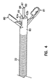
- Figure 4 is a perspective view of the fiber tube assembly and related components, for the distal end of the device of Fig. 2;
- Figure 5A is a top view, at an enlarged scale, of a component of the distal end of the device of Fig. 2;
- Figure 5B is a side sectional view taken along the
line 5B-5B of Figure 5A; - Figure 5C is an end view of the component of the distal end of the device of Fig. 2;
- Figure 6A and 6B are top and side views, respectively, of a cutting jaw component of the distal end of the device of Fig. 2;
- Figure 7 is an overall view of another embodiment of the optical biopsy forceps according to the present invention; and
- Figure 8 is a cross-sectional view of the distal end of an optical biopsy forceps provided in accordance with a further embodiment of the invention.
- One preferred embodiment of an integrated optical biopsy forceps of the present invention is generally indicated by
reference number 10 in Fig. 1.Forceps 10 is adapted for use internally in the body, for example in connection with endoscopic, laparoscopic or vascular procedures.Forceps 10 includes acontrol handle portion 12 at the proximal end, amiddle portion 14 which extends over the main length of the device, and adistal end 16 which includes opposed forceps cutting jaws and distal end of the optical fiber, as is explained in greater detail below. - As seen in the left portion of Fig. 2, the main body or length of the
forceps 10 consists of coaxial inner and an outer tubular members. In one preferred embodiment, the inner tubular member is a hollowplastic tube 20, and the outer tubular member or catheter body iscoil 22. Thecoil 22 is a finely wound spiral coil of stainless steel as is generally known and used in catheters and guidewires. Alternatively, the outer tubular member could be made using another plastic tube, or a plastic/metal composite structure, in place ofcoil 22. Theplastic tube 20 is positioned withincoil 22 and these components are dimensioned with respect to each other so thattube 20 may be free to move axially withincoil 22 during actuation of the jaws, as is explained below. - Positioned within
inner tube 20 are a pair ofcontrol wires optical fiber 50. These components, together withouter coil 22 and innerplastic tube 20 extend over the main length of the device, from thedistal end 16 to thehandle portion 12. At the handle,coil 22 andtube 20 pass through aplastic sleeve 24, which serves as a reinforcement and strain relief, into abore 25 in thetip 13 of thehandle 12. Theplastic sleeve 24 and the proximal end of thecoil 22 are received and secured, as by bonding, in thetip 13 of thehandle 12. - The inner
plastic tube 20,control wires fiber 50 are not secured attip 13, but pass throughbore 25, through a stainlesssteel reinforcing tube 29 toslider 30, which is movably received in aslot 28 inhandle 12. Reinforcingtube 29,tube 20 andcontrol wires slider 30 which together form an actuator mechanism for theforceps 10. Movement ofslider 30 causes axial movement of reinforcingtube 29,tube 20 andcontrol wires coil 22, which is used to actuate the cutting jaws.Loops handle 12 andslider 30, to form finger holes useful in grasping and manipulating the forceps. -
Optical fiber 50 extends throughslider 30, and out ofhandle 12, in a protective cable orsheath 32, for connection to electro-optical units (not shown) which provide the illumination light to the fiber, and which receive and analyze the returned right from the target at distal the end of the forceps. The optical biopsy forceps of the present invention may be used with any type of electro-optical technique for guiding the forceps. This may include systems which use viewing or imaging, systems which use illumination with white light to excite dyes in the area of interest, and spectroscopic techniques to identify tissue types by spectral analysis of light returned from tissue illuminated with light of certain wavelengths. Such spectroscopic techniques utilize the property of certain tissue types to reflect or fluoresce light having characteristic wavelengths. - As seen in Figs. 2, 5A, 5B and 5C, the
distal end 16 of the optical forceps includes ayoke 60, which serves as a mounting member for the cutting jaws.Yoke 60 may be machined from stainless steel or formed of other suitable material. It generally has a proximal portion or section indicated byreference number 61, acenter section 62, and adistal section 63 having inwardly curved opposingdistal end portions Yoke 60 has abore 64 running therethrough. Each of the opposingdistal end portions fiber 50. The diameter of the bore defined by thearcuate grooves 65 can be stepped to a smaller size atdistal end portions Sections Section 61 has a diameter corresponding to the inside dimension ofcoil 22, whilesection 62 has a diameter corresponding to the outside dimension ofcoil 22, so that the end ofcoil 22 may be received and bonded tosection 61. Theproximal end surface 56 of theyoke 60 cooperates with thedistal end 21 of theinner tube 20 to provide a limit stop for thefiber tube assembly 52 when it is being advanced within theouter tube 22 to open the jaws.Center section 62 has a pair ofholes -
Distal section 63 is stepped down relative tosection 62, as seen in side view in Figs. 2 and 5B, to allow thejaws Distal section 63 also has avertical slot 70 provided therein which is dimensioned to the size of the mounting ends of thelever arms 85 of the jaws. Theinner wall 71 ofdistal section 63 is stepped outwardly relative to theslot 70 to provide clearance for the ends ofcontrol wires - Because
jaws jaw 80 has a rearward lever or mountingportion 85, and a distal cup orsample receiving portion 82, which hassharp serrations 83 used to cut the tissue sample. Thelever portion 85 has ahole 84 formed to receive thepin 72 which thus serves to retain the jaws, and also to acts as the pivot point. Ahole 86 is provided at the forward apex of the relieved section, to receive the end of control wire 40 (or 41) which is crimped or bent at a right angle at its tip to be effectively captured. The control wires are formed of wire which is stiff enough to push against the jaws to open them, but flexible enough to flex as the wires are retracted to pull the jaws together. - As seen in Fig. 2, the
distal end 16 of the optical forceps also includes afiber tube assembly 52. It includes atube 54 which may be machined from stainless steel, or formed of other suitable material. The end ofplastic tube 20 overlaps end 55 of thetube 54 and is bonded totube 54. Thecontrol wires optical fiber 50 pass into it from theplastic tube 20. The optical fiber and the control wires pass axially through thetube 54 and are bonded to thetube 54 by epoxy or other suitable adhesive. Theoptical fiber 50 includes ajacket 87 of polyamide or similar material and an outerprotective tube 88 made of stainless steel, for example. Thejacket 87 extends the length of the optical fiber from its proximal end to its proximal end. Theprotective tube 88 extends from the distal end of the optical fiber to at least a point located within the distal end oftube 54. The distal end of theoptical fiber 50 is flush with the end of theprotective tube 88, and may have a lens or clear epoxy coating, depending on the optical properties desired. Theprotective tube 88 at the distal end of the optical fiber is designed to give strength to prevent damage to the fiber by tweezers and the like when tissue is removed from the biopsy jaws. - Referring to Figs. 1 and 2, in operation, the
slider 30 is retracted toward the back ofhandle 12 to close the jaws. This causes movement (to the left in Fig. 2) ofplastic tube 20, thefiber tube assembly 52, thecontrol wires optical fiber 50. This retracts the optical fiber into theyoke 60 and the pulling of the control wires closes the jaws. In this configuration, the distal end is of the same narrow diameter as the main body of the forceps catheter, and the closed jaws have a smooth, rounded shape to facilitate introduction and navigation in the vascular, endoscopic or laproscopic systems. Also, the cutting jaws are coaxially positioned with respect to the distal end of the optical fiber. - Once in place in the general area of interest, the forceps jaws can be opened by pushing
slider 30 of the control handle forward. This causes movement (to the right in Fig. 2) ofplastic tube 20, thefiber tube assembly 52, thecontrol wires optical fiber 50. The control wires push against the jaws, causing them to open. Simultaneously, the tip of the optical fiber is axially extended. The distal end or tip of the optical fiber is positioned at the distal end of the catheter body with its optical view axis or view axis aligned for a tissue analysis zone adjacent the distal tip of the catheter body and positioned at the area of contact of the cutting jaws when the cutting jaws are operated to their closed cutting position. The device may then be used for optical tissue identification. When an area of disease is identified and a biopsy of it is needed,slider 30 is pulled, retracting the tip of the fiber and simultaneously causing the jaws to close and cut a biopsy sample at the exact place being viewed by the fiber. The biopsy sample is cut from the exact tissue site identified by the spectroscopic analysis step without requiring moving or repositioning of the catheter body. The forceps may then be withdrawn from the patient to recover the sample for analysis. The analysis of the withdrawn sample can be conducted using known laboratory techniques to confirm the identification of the tissue sample made by spectroscopic analysis. - The optical biopsy forceps of the invention is used for spectroscopically analyzing tissue in the tissue analysis zone adjacent the distal end of the forceps through the use of an electro-optic tissue analysis system connected to the proximal end of the optical fiber. The optical biopsy forceps are guided spectroscopically within the body to an area of interest as identified by the spectroscopic analysis of tissue type in the tissue analysis zone adjacent the distal tip of the catheter body.
- Referring to Fig. 7, another embodiment of an integrated optical biopsy forceps of the present invention is generally indicated by
reference number 90. Theoptical forceps 90 is generally similar to theoptical forceps 10 shown in Fig. 1, and accordingly, corresponding elements have been given the same reference number. The optical biopsy forceps is adapted for use internally in the body, for example in connection with endoscopic, laparoscopic or vascular procedures.Forceps 90 includes ahandle portion 91 and an operatinglever 92 at the proximal end, amiddle portion 14 which extends over the main length of the device, and adistal end 16. Thedistal end 16 includesforceps cutting jaws optical fiber 50 which is contained within a plastic tube, corresponding toplastic tube 20 offorceps 10, and pass through asleeve 24 in the manner illustrated in Figs. 1-6 for theforceps 10. - The operating
lever 92 has itsupper end 93 pivoted to thehandle 91 by apivot pin 94. Theforceps 90 includes a reinforcing tube, corresponding to reinforcingtube 29 offorceps 10, which encloses the fiber optical tube, andcontrol wires post 95 and are secured to the operatinglever 92 near itsupper end 93 located within the handle. The optical fiber tube extends out of the handle in aprotective sheath 32 as described above with reference tooptical biopsy forceps 10.Loops 97 are provided in thehandle 91 and the operatinglever 92, forming finger holes useful in grasping and manipulating the forceps. The operating lever also hascurved regions 99 forming finger rests, which together with the depending operating lever arrangement of theforceps 90, enhance the ergonomics of the instrument. - The
jaws handle 91 and the operatinglever 92 is as illustrated in Fig. 6. When the operatinglever 92 is moved rearwardly toward the handle, in the direction of thearrow 89, thecontrol wires post 95, retracting the optical fiber and operating thejaws forceps 10. When the operating lever is moved in the opposite direction, the control wires are advanced withintube 20, causing the jaws to open. - Referring to Fig. 8, there is illustrated the
distal end 106 of an integrated optical biopsy forceps provided in accordance with a further embodiment of the invention. The optical biopsy forceps includes anoptical fiber 150 and opposedforceps cutting jaws forceps 10 shown in figs. 1-6. Theoptical fiber 150 of the optical biopsy forceps includes an outer tubular, sheath-like member orcatheter body 110, which corresponds to the outer sheath or coil 22 (Fig. 2), and areinforcement cover 116, which, for example, can be a metal coil or cable, a nylon sheath, or any other suitable cover. The reinforced optical fiber is movable axially within thesheath 110. The optical biopsy forceps further includes a tubular slide member connected to the optical fiber and movable therewith, and coupled to thejaws jaws outer sheath 110. - The optical biopsy forceps includes a suitable handle (not shown) for facilitating actuation of the
tubular slide member 120. Preferably, the handle is similar to the handle 12 (Fig. 1) of theoptical biopsy forceps 10, but the handle can include any type of actuating mechanism capable of imparting bidirectional axial movement to theoptical fiber 150 of the optical biopsy forceps. Referring additionally to Fig. 1, in such arrangement, theoptical fiber 150 positioned within the outer sheath, extends over the main length of the device, from thedistal end 106 to the handle. The proximal end of thesheath 110 passes through a sleeve, such assleeve 24, and is secured to the tip of the handle. The sleeve provides reinforcement and strain relief where thesheath 110 is attached to the handle. The proximal end of theoptical fiber 150 also passes throughsleeve 24 and is secured to theslider 30 of thehandle 12 distally of the proximal end of theoptical fiber 150, the end portion of which passes through the slider and out of the handle for connection to suitable electro-optical units in the manner that has been described for theoptical fiber 50 ofoptical biopsy forceps 10. Theslider 30 of the handle is adapted to push the reinforcedoptical fiber 150, which in turn pushes thetubular slide member 120, to open the jaws of the optical biopsy forceps and to pull the reinforced optical fiber, pulling thetubular slide member 120, to close the jaws. - The optical biopsy forceps of the present invention can be used with any type of electro-optical technique for guiding the forceps. This may include systems which use viewing or imaging, systems which use illumination with white light to excite dyes in the area of interest, and spectroscopic techniques to identify tissue types by spectral analysis of light returned from tissue illuminated with light of certain wavelengths. Such spectroscopic techniques utilize the property of certain tissue types to reflect or fluoresce light having characteristic wavelengths.
- Considering the optical biopsy forceps in more detail, with reference to Fig. 8, the
sheath 110 is a flexible hollow catheter which can be made a plastic tube, or a plastic/metal composite structure that defines an opening or bore therethrough. By way of example, theouter sheath 110 can be similar to those of disposable biopsy forceps commonly used with colonoscopes used in the upper and lower gastrointestinal tracts, and broncoscopes used in the trachea and bronchus. Alternatively, theouter sheath 110 can be a rigid tube, such as those of biopsy forceps commonly used with cystoscopes, colposcopes and laproscopes. - At its distal end, the
optical fiber 150 extends through acentral bore 119 formed through atubular slide member 120 which, in turn, is mounted in a mounting member or jaw support block 122 which serves as a mounting member for the cuttingjaws jaw support block 122 can be machined from stainless steel or formed of other suitable material. Thejaw support block 122 has abore 124 running therethrough which is generally circular in section. The inner dimension of thejaw support block 122 corresponds to the outer dimension of theouter sheath 110 which is secured to the support block in a suitable manner, such as with cement or by crimping. Thejaws support block 122 which has a pair of holes which receive pins 130, 132 which pass throughears 134 of the jaws to hold thejaws ears 134, as seen in side view in Fig. 8, allows thejaws jaw support block 122 has a slot to control travel of thejaws - The
tubular slide member 120 is mounted in thebore 124 in thejaw support block 122 and is free to move axially withinsupport block 122 during actuation of the jaws. Thefiber 150 is secured to thetubular slide member 120 in a suitable manner such as with cement. Thejaws tubular slide member 120 by a pair ofcontrol links Control link 136 has oneend 139 connected totubular slide member 120 by apin 140. Theother end 141 of thecontrol link 136 is connected tojaw 180 by apin 142. Similarly, control link 138 has oneend 144 connected totubular slide member 120 by apin 146 and itsother end 148 connected tojaw 181 by apin 149. Thus, axial movement of the optical fiber in the direction ofarrow 154, as the optical fiber is retracted, causes axial movement oftubular slide member 120, pivoting thecontrol links ends jaws rearward surface 151 at the distal end 152 of thetubular slide member 120 is adapted to engage theforward surface 153 of thejaw support block 122, functioning as a travel limit stop surface to limit the axial movement of thetubular slide member 120 during retraction of theoptical fiber 150. Similarly, when theoptical fiber 150 is advanced into the sheath 112, thetubular slide member 120 is moved axially in the opposite direction, causing thecontrol links forward surface 161 at the proximal end 162 of thetubular slide member 120 is adapted to engage therearward surface 163 of thejaw support block 122, functioning as a travel limit stop surface to limit the axial movement of thetubular slide member 120 during retraction of theoptical fiber 150. Thus, both the proximal and distal ends of thetubular slide member 120 include limit stops which prevent both over distention and over retraction of theoptical fiber 150. - Referring additionally to Fig. 1, in operation of the optical biopsy forceps, initially, the
optical fiber 150 is fully retracted (by retracting theslider 30 toward the back of the handle) to move thetubular slide member 120 in the direction of thearrow 154 until itsrearward surface 151 engages forward surface 152 of thejaw support block 122. In this position, thecontrol links jaws distal end 106 of the forceps is substantially of the same narrow diameter as theouter sheath 116 which defines the main body portion of the optical biopsy forceps, and the closed jaws have a smooth, rounded shape to facilitate introduction and navigation through the biopsy channel of an endoscope, for example - The endoscopist advances the optical biopsy forceps through the biopsy channel of the endoscope to the general area of interest, i.e., such as a tissue site or tissue analysis zone with a body, represented by the
reference numeral 170. Once in place in the general area of interest, the forceps jaws can be opened by advancing theslider 30, thereby advancing theoptical fiber 150 forwardly through the handle. This causes thetubular slide member 120 to move forwardly (to the right in Fig. 8), which in turn causes pivoting of thecontrol links optical fiber 150 is axially extended forwardly beyond the jaws. The forceps may then be used for optical tissue identification. - When an area of disease is identified and if a biopsy of it is needed, the
slider 30 is retracted, retracting theoptical fiber 150 and thus thetubular slide member 120, retracting the tip of the optical fiber and simultaneously causing the jaws to close and cut a biopsy sample at the exact place that has been located by viewing through the optical fiber. To take the tissue sample, the endoscopist holding the instrument by the handle, gently pulls back on the slider of the handle, retracting the optical fiber andtubular slide member 120, moving the optical fiber away from the tissue surface. As the optical fiber is being retracted, the jaws begin to close as the tubular slide member is moved in the direction of thearrow 154. While the jaws are being closed, the endoscopist gently pushes on the instrument to urge the jaws towards the tissue surface so that a tissue sample will be captured by the jaws as they close. When the jaws are closed, the endoscopist pulls the entire assembly away from the tissue surface and then withdraws the optical biopsy forceps from the endoscope so that the specimen tissue can be retrieved. - Thus, the present invention has provided an optical biopsy forceps. An important feature of the invention is that the tip of the optical fiber 50 (and optical fiber 150) is coaxial with, and perfectly aligned with, the zone where the two
jaws 80, 81 (andjaws 180, 181) intersect and the sample is taken. Thus, there is no offset or 'parallax' error between the spot where the optical measurements were taken and the spot from which the biopsy sample will be taken. This, together with the slim and compact profile of the device when the jaws are retracted, is a great improvement over prior art devices. In accordance with another feature, the fiber optic assembly, including the optical fiber and the tubular slide member of the biopsy forceps, can be produced as a disposable assembly, with the rest of the biopsy forceps being produced as a non-disposable unit. The major advantage offorceps 100 as compared toforceps 10 is, because the biopsyjaw control wires - It will be appreciated from the foregoing that we have provided an improved optical biopsy forceps which provides the physician a greater degree of accuracy and control over the diagnosis process than was previously possible. While we have illustrated the invention with two illustrative embodiments of the invention, it will be appreciated that variations of shapes, materials and assembly are possible, within the scope of the invention.
Claims (10)
- An integrated optical biopsy forceps, comprising:a flexible catheter body (22) having a bore therethrough, and having proximal and distal ends;an optical fibre (50) extending through the catheter body (22) and adapted at its proximal end for connection to an electro-optical tissue analysis system, the distal end of the optical fibre positioned at the distal end of the catheter body and having an optical viewing axis said distal end of the optical fibre and said optical viewing axis being aligned with a tissue analysis zone adjacent the distal end of the catheter body;cutting jaws (80, 81) mounted at the distal end of the catheter body for selective opening and closing in a biopsy cutting movement, said cutting jaws positioned coaxially with said viewing axis and having a closed cutting position on the optical viewing axis and enclosing the tissue analysis zone; andan actuator mechanism (27, 30) operatively connected to the cutting jaws and mounted at the proximal end of the catheter body for selectively controlling from the proximal end the opening and closing of the cutting jaws to cut a biopsy sample at the exact location of the tissue analysis zone, the actuator mechanism including control wires (40, 41) connected to the cutting jaws for causing opening and closing of the cutting jaws by axial movement of the control wires;characterised in that the actuator mechanism retracts the distal end of the optical fibre (50) as the cutting jaws close together.
- A forceps according to claim 1, wherein the catheter body includes a tubular member (29) coupled to the optical fiber (50), and wherein the actuator mechanism includes a slider (30) mounted to a handle (12) for movement relative thereto, the control wires (40, 41) being connected to the slider, the slider being operative to differentially push the tubular member to open the cutting jaws and extend the distal end of the optical fiber (50) and to pull the control wires and the tubular member to retract the distal end of the optical fiber and close the cutting jaws in taking a biopsy sample.
- A forceps according to claim 1, wherein the flexible catheter body has coaxial inner (20) and outer (22) tubular members extending between proximal and distal ends of the forceps;
a mounting member (60) connected to the outer tubular member (22) at the distal end of the forceps for mounting the jaws (80, 81) for selective opening and closing in a biopsy cutting movement,
the optical fiber (50) extending through the inner tubular member (20) of the catheter body,
a control handle (12) at the proximal end of the forceps, the control handle receiving the proximal end of the optical fiber for connection thereof to an electro-optic tissue analysis system, and receiving the inner and outer tubular members and the control wires; and
the control handle having an actuator control (26, 30) for differentially pushing the outer tubular member and pulling the control wires and inner tubular member, to retract the distal end of the optical fiber and close the cutting jaws, thereby taking a biopsy sample at the exact area of view of optical tissue analysis. - A forceps according to claim 3, wherein the actuator mechanism includes a slider (30) mounted to the handle and movable relative thereto, the control wires being secured to the slider, the slider being adapted to pull the control wires to close the jaws and to push the inner tubular member to open the jaws.
- A forceps according to claim 3, wherein the inner tubular member includes a distal tube portion (52) that is connected to the optical fiber and movable axially of the catheter body.
- A forceps according to claim 5, wherein the distal end of the inner tubular member (20) is adapted to cooperate with the mounting member (60) to provide a limit stop for the distal tube portion and the optical fiber connected thereto.
- A forceps according to claim 1, further comprising an inner tubular member (20) received by an outer tubular member (22), where the optical fiber (50) is disposed within the inner tubular member (20) and extends through the catheter body.
- A forceps according to claim 7, wherein the outer tubular member (22) is a coil, and the inner tubular member (20) is a tube.
- A forceps according to claim 7, wherein the inner tubular member (20) is co-axial with the outer tubular member (22).
- A forceps according to claim 7, wherein the cutting jaws (80, 81) are adapted to receive the inner tubular member therethrough.
Applications Claiming Priority (3)
| Application Number | Priority Date | Filing Date | Title |
|---|---|---|---|
| US644080 | 1996-05-07 | ||
| US08/644,080 US5762613A (en) | 1996-05-07 | 1996-05-07 | Optical biopsy forceps |
| PCT/US1997/007624 WO1997041776A1 (en) | 1996-05-07 | 1997-05-07 | Optical biopsy forceps |
Publications (2)
| Publication Number | Publication Date |
|---|---|
| EP0910284A1 EP0910284A1 (en) | 1999-04-28 |
| EP0910284B1 true EP0910284B1 (en) | 2007-01-24 |
Family
ID=24583369
Family Applications (1)
| Application Number | Title | Priority Date | Filing Date |
|---|---|---|---|
| EP97922685A Expired - Lifetime EP0910284B1 (en) | 1996-05-07 | 1997-05-07 | Optical biopsy forceps |
Country Status (7)
| Country | Link |
|---|---|
| US (2) | US5762613A (en) |
| EP (1) | EP0910284B1 (en) |
| JP (1) | JP3220164B2 (en) |
| AT (1) | ATE352256T1 (en) |
| CA (1) | CA2253643C (en) |
| DE (1) | DE69737289T2 (en) |
| WO (1) | WO1997041776A1 (en) |
Cited By (9)
| Publication number | Priority date | Publication date | Assignee | Title |
|---|---|---|---|---|
| US7952718B2 (en) | 2007-05-03 | 2011-05-31 | University Of Washington | High resolution optical coherence tomography based imaging for intraluminal and interstitial use implemented with a reduced form factor |
| WO2012149643A1 (en) * | 2011-05-04 | 2012-11-08 | George Klein | Ablation grasper |
| US8382662B2 (en) | 2003-12-12 | 2013-02-26 | University Of Washington | Catheterscope 3D guidance and interface system |
| US8396535B2 (en) | 2000-06-19 | 2013-03-12 | University Of Washington | Integrated optical scanning image acquisition and display |
| US8537203B2 (en) | 2005-11-23 | 2013-09-17 | University Of Washington | Scanning beam with variable sequential framing using interrupted scanning resonance |
| US8840566B2 (en) | 2007-04-02 | 2014-09-23 | University Of Washington | Catheter with imaging capability acts as guidewire for cannula tools |
| US9161684B2 (en) | 2005-02-28 | 2015-10-20 | University Of Washington | Monitoring disposition of tethered capsule endoscope in esophagus |
| US9561078B2 (en) | 2006-03-03 | 2017-02-07 | University Of Washington | Multi-cladding optical fiber scanner |
| EP2519300B1 (en) | 2009-12-29 | 2020-08-12 | Acclarent, Inc. | System for treating target tissue within the eustachian tube |
Families Citing this family (131)
| Publication number | Priority date | Publication date | Assignee | Title |
|---|---|---|---|---|
| US6564087B1 (en) | 1991-04-29 | 2003-05-13 | Massachusetts Institute Of Technology | Fiber optic needle probes for optical coherence tomography imaging |
| US6485413B1 (en) | 1991-04-29 | 2002-11-26 | The General Hospital Corporation | Methods and apparatus for forward-directed optical scanning instruments |
| US6111645A (en) | 1991-04-29 | 2000-08-29 | Massachusetts Institute Of Technology | Grating based phase control optical delay line |
| US5762613A (en) * | 1996-05-07 | 1998-06-09 | Spectrascience, Inc. | Optical biopsy forceps |
| US6296608B1 (en) * | 1996-07-08 | 2001-10-02 | Boston Scientific Corporation | Diagnosing and performing interventional procedures on tissue in vivo |
| US6508825B1 (en) | 1997-02-28 | 2003-01-21 | Lumend, Inc. | Apparatus for treating vascular occlusions |
| US6217549B1 (en) | 1997-02-28 | 2001-04-17 | Lumend, Inc. | Methods and apparatus for treating vascular occlusions |
| WO1998040015A2 (en) * | 1997-03-13 | 1998-09-17 | Biomax Technologies, Inc. | Catheters and endoscopes comprising optical probes and bioptomes and methods of using the same |
| US6201989B1 (en) | 1997-03-13 | 2001-03-13 | Biomax Technologies Inc. | Methods and apparatus for detecting the rejection of transplanted tissue |
| US6368327B2 (en) * | 1997-04-29 | 2002-04-09 | Raymond F. Lippitt | Medical device |
| US6484050B1 (en) * | 1997-11-18 | 2002-11-19 | Care Wise Medical Products Corporation | Minimally invasive surgical instrument for tissue identification, dislodgment and retrieval and methods of use |
| US5961458A (en) * | 1997-11-18 | 1999-10-05 | Carewise Medical Products Corporation | Minimally invasive surgical probe for tissue identification and retrieval and method of use |
| US6066102A (en) * | 1998-03-09 | 2000-05-23 | Spectrascience, Inc. | Optical biopsy forceps system and method of diagnosing tissue |
| US6174291B1 (en) | 1998-03-09 | 2001-01-16 | Spectrascience, Inc. | Optical biopsy system and methods for tissue diagnosis |
| US6299860B1 (en) * | 1998-10-15 | 2001-10-09 | Fluoro Probe, Inc. | Method for viewing diseased tissue located within a body cavity |
| US6652836B2 (en) | 1998-10-15 | 2003-11-25 | Fluoroprobe, Inc. | Method for viewing tumor tissue located within a body cavity |
| US6284223B1 (en) * | 1998-10-15 | 2001-09-04 | Fluoroprobe, Inc. | Method for viewing tumor tissue located within a body cavity |
| US6248124B1 (en) * | 1999-02-22 | 2001-06-19 | Tyco Healthcare Group | Arterial hole closure apparatus |
| US6445939B1 (en) | 1999-08-09 | 2002-09-03 | Lightlab Imaging, Llc | Ultra-small optical probes, imaging optics, and methods for using same |
| US6308092B1 (en) * | 1999-10-13 | 2001-10-23 | C. R. Bard Inc. | Optical fiber tissue localization device |
| JP3655785B2 (en) * | 1999-10-18 | 2005-06-02 | ペンタックス株式会社 | Endoscopic treatment tool |
| ITCE990004A1 (en) | 1999-10-25 | 2000-01-25 | Mario Immacolato Paternuosto | VALVE FOR BIOPSY FORCEPS IN DIGESTIVE ENDOSCOPY |
| US6416519B1 (en) * | 1999-11-15 | 2002-07-09 | Vandusseldorp Gregg A. | Surgical extraction device |
| US6858005B2 (en) * | 2000-04-03 | 2005-02-22 | Neo Guide Systems, Inc. | Tendon-driven endoscope and methods of insertion |
| US8517923B2 (en) | 2000-04-03 | 2013-08-27 | Intuitive Surgical Operations, Inc. | Apparatus and methods for facilitating treatment of tissue via improved delivery of energy based and non-energy based modalities |
| US6610007B2 (en) | 2000-04-03 | 2003-08-26 | Neoguide Systems, Inc. | Steerable segmented endoscope and method of insertion |
| US6468203B2 (en) | 2000-04-03 | 2002-10-22 | Neoguide Systems, Inc. | Steerable endoscope and improved method of insertion |
| US8888688B2 (en) | 2000-04-03 | 2014-11-18 | Intuitive Surgical Operations, Inc. | Connector device for a controllable instrument |
| US20020058961A1 (en) * | 2000-10-16 | 2002-05-16 | Aguilar Amiel R. | Catheter |
| US20050010235A1 (en) * | 2003-07-09 | 2005-01-13 | Vandusseldorp Gregg A. | Surgical device |
| US8062314B2 (en) * | 2000-12-06 | 2011-11-22 | Ethicon Endo-Surgery, Inc. | Methods for the endoluminal treatment of gastroesophageal reflux disease (GERD) |
| IL140136A (en) * | 2000-12-06 | 2010-06-16 | Intumed Ltd | Apparatus for self-guided intubation |
| US7232445B2 (en) * | 2000-12-06 | 2007-06-19 | Id, Llc | Apparatus for the endoluminal treatment of gastroesophageal reflux disease (GERD) |
| US20020138086A1 (en) * | 2000-12-06 | 2002-09-26 | Robert Sixto | Surgical clips particularly useful in the endoluminal treatment of gastroesophageal reflux disease (GERD) |
| US7727246B2 (en) * | 2000-12-06 | 2010-06-01 | Ethicon Endo-Surgery, Inc. | Methods for endoluminal treatment |
| US6716226B2 (en) * | 2001-06-25 | 2004-04-06 | Inscope Development, Llc | Surgical clip |
| US20020068945A1 (en) * | 2000-12-06 | 2002-06-06 | Robert Sixto | Surgical clips particularly useful in the endoluminal treatment of gastroesophageal reflux disease (GERD) |
| US20020143358A1 (en) * | 2001-02-13 | 2002-10-03 | Domingo Nicanor A. | Method and apparatus for micro-dissection of vascular occlusions |
| JP4295925B2 (en) * | 2001-03-01 | 2009-07-15 | Hoya株式会社 | Bipolar high-frequency treatment instrument for endoscope |
| US6808491B2 (en) | 2001-05-21 | 2004-10-26 | Syntheon, Llc | Methods and apparatus for on-endoscope instruments having end effectors and combinations of on-endoscope and through-endoscope instruments |
| JP5073895B2 (en) | 2001-09-25 | 2012-11-14 | オリンパス株式会社 | Endoscopic treatment tool |
| CN1764416A (en) | 2002-01-09 | 2006-04-26 | 新引导系统公司 | Apparatus and method for endoscopic colectomy |
| CN1617687A (en) | 2002-01-09 | 2005-05-18 | 新引导系统公司 | Apparatus and method for spectroscopic examination of the colon |
| JP4131011B2 (en) * | 2002-04-09 | 2008-08-13 | Hoya株式会社 | Endoscopic sputum treatment device |
| US20030225432A1 (en) * | 2002-05-31 | 2003-12-04 | Baptiste Reginald C. | Soft tissue retraction device for an endoscopic instrument |
| JP4420593B2 (en) * | 2002-07-29 | 2010-02-24 | Hoya株式会社 | Bipolar high-frequency treatment instrument for endoscope |
| DE10255082A1 (en) * | 2002-11-20 | 2004-06-17 | Aesculap Ag & Co. Kg | endoscope |
| DE10258483B3 (en) * | 2002-12-10 | 2004-06-17 | Universitätsklinikum Charité, Medizinische Fakultät der Humboldt-Universität zu Berlin | Optical biopsy instrument for extracting breast tissue sample from milk duct having endoscope displaced within cylindrical channel having side opening with cutting edge |
| US8882657B2 (en) | 2003-03-07 | 2014-11-11 | Intuitive Surgical Operations, Inc. | Instrument having radio frequency identification systems and methods for use |
| JP4131014B2 (en) * | 2003-03-18 | 2008-08-13 | Hoya株式会社 | Endoscopic sputum treatment device |
| JP4653104B2 (en) * | 2003-06-10 | 2011-03-16 | ルーメンド インコーポレイテッド | Catheter apparatus and method for opening a vascular occlusion |
| US8469993B2 (en) | 2003-06-18 | 2013-06-25 | Boston Scientific Scimed, Inc. | Endoscopic instruments |
| US20040260337A1 (en) * | 2003-06-18 | 2004-12-23 | Scimed Life Systems, Inc. | Endoscopic instruments and methods of manufacture |
| US7775989B2 (en) * | 2003-09-03 | 2010-08-17 | Granit Medical Innovations, Llc | Needle biopsy forceps with integral sample ejector |
| EP2455016B1 (en) * | 2003-09-09 | 2014-06-18 | Olympus Corporation | Treatment tool for endoscope |
| JP4593096B2 (en) * | 2003-09-09 | 2010-12-08 | オリンパス株式会社 | Endoscopic treatment tool |
| US7588545B2 (en) | 2003-09-10 | 2009-09-15 | Boston Scientific Scimed, Inc. | Forceps and collection assembly with accompanying mechanisms and related methods of use |
| US7942896B2 (en) * | 2003-11-25 | 2011-05-17 | Scimed Life Systems, Inc. | Forceps and collection assembly and related methods of use and manufacture |
| ES2409160T3 (en) * | 2004-03-23 | 2013-06-25 | Boston Scientific Limited | Live View System |
| WO2006005075A2 (en) * | 2004-06-30 | 2006-01-12 | Amir Belson | Apparatus and methods for capsule endoscopy of the esophagus |
| ATE440552T1 (en) * | 2005-01-20 | 2009-09-15 | Wilson Cook Medical Inc | BIOPSY FORCEPS |
| WO2006078694A2 (en) | 2005-01-21 | 2006-07-27 | Mayo Foundation For Medical Education And Research | Thorascopic heart valve repair method and apparatus |
| EP1885259B1 (en) * | 2005-05-11 | 2016-08-17 | Mayo Foundation For Medical Education And Research | Apparatus for internal surgical procedures |
| US7762960B2 (en) | 2005-05-13 | 2010-07-27 | Boston Scientific Scimed, Inc. | Biopsy forceps assemblies |
| JP4880251B2 (en) * | 2005-06-21 | 2012-02-22 | オリンパスメディカルシステムズ株式会社 | High frequency treatment tool |
| US7658708B2 (en) * | 2005-09-20 | 2010-02-09 | Ai Medical Devices, Inc. | Endotracheal intubation device |
| EP1948056A2 (en) * | 2005-10-24 | 2008-07-30 | Spectrascience, Inc. | System and method for non-endoscopic optical biopsy detection of diseased tissue |
| EP3788944B1 (en) | 2005-11-22 | 2024-02-28 | Intuitive Surgical Operations, Inc. | System for determining the shape of a bendable instrument |
| JP2009517608A (en) | 2005-11-23 | 2009-04-30 | ネオガイド システムズ, インコーポレイテッド | Non-metallic multi-strand control cable for steerable devices |
| US20070244510A1 (en) | 2006-04-14 | 2007-10-18 | Ethicon Endo-Surgery, Inc. | Endoscopic device |
| US7857827B2 (en) | 2006-04-14 | 2010-12-28 | Ethicon Endo-Surgery, Inc. | Endoscopic device |
| US7998167B2 (en) | 2006-04-14 | 2011-08-16 | Ethicon Endo-Surgery, Inc. | End effector and method of manufacture |
| WO2007137208A2 (en) | 2006-05-19 | 2007-11-29 | Neoguide Systems, Inc. | Methods and apparatus for displaying three-dimensional orientation of a steerable distal tip of an endoscope |
| DE102006028001B4 (en) * | 2006-06-14 | 2009-11-26 | Paul Peschke Gmbh | Surgical grasping forceps |
| US8114121B2 (en) | 2006-06-22 | 2012-02-14 | Tyco Healthcare Group Lp | Tissue vitality comparator with light pipe with fiber optic imaging bundle |
| EP2040612A2 (en) * | 2006-07-18 | 2009-04-01 | Trustees of Boston University | Device with integrated multi-fiber optical probe and methods of use |
| US20080045859A1 (en) * | 2006-08-19 | 2008-02-21 | Fritsch Michael H | Devices and Methods for In-Vivo Pathology Diagnosis |
| US20080097519A1 (en) * | 2006-10-20 | 2008-04-24 | Alfred E. Mann Foundation For Scientific Research | Medical device extraction tool |
| EP1955657B1 (en) * | 2007-02-08 | 2011-01-12 | Olympus Medical Systems Corp. | Treatment tool for endoscope |
| JP4526544B2 (en) * | 2007-02-08 | 2010-08-18 | オリンパスメディカルシステムズ株式会社 | Endoscopic treatment tool |
| BRPI0807770A2 (en) * | 2007-02-19 | 2014-06-24 | Multi Biopsy Sampling Co Aps | Biopsy Forceps for one or more samples. |
| EP1985329B1 (en) * | 2007-04-25 | 2010-06-02 | Olympus Medical Systems Corp. | Tubular member and endoscopic instrument |
| EP2197340A4 (en) * | 2007-09-19 | 2015-10-21 | Oncofluor Inc | Method for imaging and treating organs and tissues |
| US9220398B2 (en) | 2007-10-11 | 2015-12-29 | Intuitive Surgical Operations, Inc. | System for managing Bowden cables in articulating instruments |
| JP5357167B2 (en) | 2007-10-18 | 2013-12-04 | ネオコード インコーポレイテッド | Instrument for repairing pulsating leaflets in the heart with minimal invasiveness |
| WO2009060460A2 (en) * | 2007-11-09 | 2009-05-14 | Given Imaging Ltd. | Apparatus and methods for capsule endoscopy of the esophagus |
| WO2009082477A2 (en) * | 2007-12-18 | 2009-07-02 | Bovie Medical | Surgical apparatus with removable tool cartridge |
| JP5818438B2 (en) | 2007-12-21 | 2015-11-18 | スミス アンド ネフュー インコーポレーテッドSmith & Nephew,Inc. | Many portal guides |
| US9826992B2 (en) | 2007-12-21 | 2017-11-28 | Smith & Nephew, Inc. | Multiple portal guide |
| KR101707924B1 (en) | 2008-02-06 | 2017-02-17 | 인튜어티브 서지컬 오퍼레이션즈 인코포레이티드 | A segmented instrument having braking capabilities |
| US8221418B2 (en) | 2008-02-07 | 2012-07-17 | Tyco Healthcare Group Lp | Endoscopic instrument for tissue identification |
| US8182418B2 (en) | 2008-02-25 | 2012-05-22 | Intuitive Surgical Operations, Inc. | Systems and methods for articulating an elongate body |
| EP2265184A1 (en) * | 2008-03-06 | 2010-12-29 | Trustees of Boston University | Low cost disposable medical forceps to enable a hollow central channel for various functionalities |
| WO2009150563A2 (en) * | 2008-06-12 | 2009-12-17 | Koninklijke Philips Electronics N.V. | Biopsy device with acoustic element |
| US9610095B2 (en) | 2008-08-27 | 2017-04-04 | Spine View, Inc. | Retractor cannula system for accessing and visualizing spine and related methods |
| US8267869B2 (en) * | 2008-12-31 | 2012-09-18 | Manua Kea Technologies | Multi-purpose biopsy forceps |
| US9433421B2 (en) * | 2010-03-12 | 2016-09-06 | Jms Co., Ltd. | Surgical tool for anastomosis |
| US9737320B2 (en) * | 2010-03-18 | 2017-08-22 | Covidien Lp | Surgical grasper with integrated probe |
| WO2011137421A1 (en) * | 2010-04-30 | 2011-11-03 | Smith & Nephew, Inc. | Guide for drilling an irregular-shaped body |
| RU2013119074A (en) | 2010-09-27 | 2014-11-10 | Смит Энд Нефью, Инк. | DEVICE AND METHODS OF ITS USE DURING ARTHROSCOPIC OPERATION |
| WO2012061642A1 (en) | 2010-11-03 | 2012-05-10 | Smith & Nephew, Inc | Drill guide |
| CN103347464B (en) | 2010-12-29 | 2016-02-03 | 尼奥绰德有限公司 | The replaceable system of beating heart valve leaflet is repaired by Wicresoft |
| CN102232852A (en) * | 2011-05-06 | 2011-11-09 | 潘文胜 | Biopsy forceps using optical fiber for focusing |
| CA2837206C (en) | 2011-06-01 | 2019-09-24 | John Zentgraf | Minimally invasive repair of heart valve leaflets |
| CN102379727A (en) * | 2011-09-02 | 2012-03-21 | 王宝根 | Multifunctional biopsy forceps |
| WO2013056190A1 (en) * | 2011-10-15 | 2013-04-18 | Transmed7, Llc | Soft tissue coring biopsy devices and methods |
| DE102012109387A1 (en) * | 2012-10-02 | 2014-04-03 | Aesculap Ag | Surgical instrument and in particular electrosurgical instrument |
| US9592079B1 (en) * | 2013-03-14 | 2017-03-14 | Matt D. Pursley | Device and method for assisting removal of items endovascularly |
| EP3185783B1 (en) | 2014-08-28 | 2019-11-13 | Koninklijke Philips N.V. | Side-looking lung biopsy device |
| CZ2014691A3 (en) * | 2014-10-10 | 2016-01-06 | Oprox, A.S. | Catheter for optical biopsy |
| US20160256140A1 (en) * | 2015-03-03 | 2016-09-08 | United States Endoscopy Group, Inc. | Microforceps |
| USD779668S1 (en) | 2015-03-26 | 2017-02-21 | United States Endoscopy Group, Inc. | Grasper |
| US11337715B2 (en) | 2015-03-26 | 2022-05-24 | United States Endoscopy Group, Inc. | Endoscopic grasping device |
| USD758581S1 (en) | 2015-03-26 | 2016-06-07 | United States Endoscopy Group, Inc. | Grasper |
| US9883854B2 (en) | 2015-04-08 | 2018-02-06 | Synaptive Medical (Barbados) Inc. | Systems, devices and methods for tissue removal and analysis |
| US20160361051A1 (en) * | 2015-06-09 | 2016-12-15 | Boston Scientific Scimed, Inc. | System for the parallel delivery of an element into the esophageal mucosa |
| US20160367311A1 (en) * | 2015-06-16 | 2016-12-22 | Lawrence J. Gerrans | Instrumentation with Embedded Imaging Systems |
| WO2017059406A1 (en) | 2015-10-01 | 2017-04-06 | Neochord, Inc. | Ringless web for repair of heart valves |
| DK178989B1 (en) * | 2015-12-30 | 2017-07-31 | 3Dintegrated Aps | A surgical instrument assembly |
| WO2017176240A1 (en) | 2016-04-04 | 2017-10-12 | Gyrus Acmi, Inc., D.B.A. Olympus Surgical Technologies Amercia | An electrosurgical illuminating instrument |
| WO2017189442A1 (en) | 2016-04-25 | 2017-11-02 | Claria Medical, Inc. | Systems and methods for tissue capture and removal |
| US10213306B2 (en) | 2017-03-31 | 2019-02-26 | Neochord, Inc. | Minimally invasive heart valve repair in a beating heart |
| WO2019083896A1 (en) * | 2017-10-23 | 2019-05-02 | Claria Medical, Inc. | Systems and methods for tissue capture and removal |
| US10758214B2 (en) * | 2017-11-13 | 2020-09-01 | UVision360, Inc. | Biopsy device and method |
| US11896285B2 (en) | 2018-03-14 | 2024-02-13 | Gyrus Acmi, Inc. | Device with movable buttons or switches and visual indicator |
| EP3768176B1 (en) | 2018-03-23 | 2024-03-20 | NeoChord, Inc. | Device for suture attachment for minimally invasive heart valve repair |
| US11173030B2 (en) | 2018-05-09 | 2021-11-16 | Neochord, Inc. | Suture length adjustment for minimally invasive heart valve repair |
| US11253360B2 (en) | 2018-05-09 | 2022-02-22 | Neochord, Inc. | Low profile tissue anchor for minimally invasive heart valve repair |
| CN113194854A (en) | 2018-09-07 | 2021-07-30 | 尼奥绰德有限公司 | Suture attachment device for minimally invasive heart valve repair |
| US11361918B2 (en) | 2019-03-25 | 2022-06-14 | Gyrus Acmi, Inc. | Device with movable buttons or switches and tactile identifier |
| EP3955855A4 (en) | 2019-04-16 | 2023-01-25 | NeoChord, Inc. | Transverse helical cardiac anchor for minimally invasive heart valve repair |
Family Cites Families (37)
| Publication number | Priority date | Publication date | Assignee | Title |
|---|---|---|---|---|
| US3074408A (en) * | 1961-05-22 | 1963-01-22 | Martin H Chester | Ureteral stone extractor and dilator |
| DE2424749B2 (en) * | 1973-05-23 | 1976-10-21 | Olympus Optical Co. Ltd., Tokio | ENDOSCOPE WITH A CHANNEL FOR INSERTING A FORCEPS AND SUCTIONING A LIQUID SUBSTANCE |
| DK131542C (en) * | 1974-02-06 | 1976-02-09 | Akad Tekn Videnskaber | SURGICAL INSTRUMENT FOR SAMPLING BIOLOGICAL SAMPLES |
| US4027510A (en) * | 1974-05-15 | 1977-06-07 | Siegfried Hiltebrandt | Forceps |
| JPS5933388B2 (en) * | 1976-03-19 | 1984-08-15 | 高美 上原 | Single-operable biopsy fiberscope |
| GB2125702A (en) * | 1982-03-16 | 1984-03-14 | Laserscope Inc | Surgical device for internal operations |
| US4557255A (en) * | 1983-08-22 | 1985-12-10 | Goodman Tobias M | Ureteroscope |
| JPS60104915A (en) * | 1983-11-11 | 1985-06-10 | Fuji Photo Optical Co Ltd | Endoscope |
| DE3347671A1 (en) * | 1983-12-31 | 1985-07-11 | Richard Wolf Gmbh, 7134 Knittlingen | TISSUE SAMPLING INSTRUMENT |
| EP0150245A1 (en) * | 1984-01-30 | 1985-08-07 | Storz, Karl, Dr.med. h.c. | Endoscope for contact-viewing |
| DE3581665D1 (en) * | 1984-05-18 | 1991-03-14 | Harald Maslanka | SURGICAL GRIPPER INSTRUMENT. |
| DE3738692A1 (en) * | 1987-11-13 | 1989-06-01 | Hannes Dr Haberl | SURGICAL PLIERS |
| US4791913A (en) * | 1987-12-14 | 1988-12-20 | Baxter Travenol Laboratories, Inc. | Optical valvulotome |
| US4887612A (en) * | 1988-04-27 | 1989-12-19 | Esco Precision, Inc. | Endoscopic biopsy forceps |
| DE3920706A1 (en) * | 1989-06-24 | 1991-01-10 | Foerster Ernst | Catheter for carrying out a biopsy - has mini-endoscope and a forceps combined with an inner sheath which slides in an outer sheath |
| US4949993A (en) * | 1989-07-31 | 1990-08-21 | Laguna Tectrix, Inc. | Exercise apparatus having high durability mechanism for user energy transmission |
| US5228451A (en) * | 1990-05-10 | 1993-07-20 | Symbiosis Corporation | Biopsy forceps device having stiff distal end |
| US5482054A (en) * | 1990-05-10 | 1996-01-09 | Symbiosis Corporation | Edoscopic biopsy forceps devices with selective bipolar cautery |
| JP3003944B2 (en) * | 1990-10-04 | 2000-01-31 | オリンパス光学工業株式会社 | Solid-state imaging device |
| US5280788A (en) * | 1991-02-26 | 1994-01-25 | Massachusetts Institute Of Technology | Devices and methods for optical diagnosis of tissue |
| US5318023A (en) * | 1991-04-03 | 1994-06-07 | Cedars-Sinai Medical Center | Apparatus and method of use for a photosensitizer enhanced fluorescence based biopsy needle |
| US5536248A (en) * | 1992-05-11 | 1996-07-16 | Arrow Precision Products, Inc. | Method and apparatus for electrosurgically obtaining access to the biliary tree and placing a stent therein |
| CA2106039A1 (en) * | 1992-09-23 | 1994-03-24 | David A. Nicholas | Surgical biopsy forceps apparatus |
| US5354291A (en) * | 1992-10-09 | 1994-10-11 | Symbiosis Corporation | Probe for endoscopic suction-irrigation instruments having a proximal port for receiving an additional probe therethrough |
| US5439000A (en) * | 1992-11-18 | 1995-08-08 | Spectrascience, Inc. | Method of diagnosing tissue with guidewire |
| US5373854A (en) * | 1993-07-15 | 1994-12-20 | Kolozsi; William Z. | Biopsy apparatus for use in endoscopy |
| US5471992A (en) * | 1994-02-08 | 1995-12-05 | Boston Scientific Corporation | Multi-motion cutter multiple biopsy sampling device |
| US5667472A (en) * | 1994-03-18 | 1997-09-16 | Clarus Medical Systems, Inc. | Surgical instrument and method for use with a viewing system |
| US5562102A (en) * | 1994-11-21 | 1996-10-08 | Taylor; Thomas V. | Multiple biopsy device |
| US5558100A (en) * | 1994-12-19 | 1996-09-24 | Ballard Medical Products | Biopsy forceps for obtaining tissue specimen and optionally for coagulation |
| US5571129A (en) * | 1995-05-15 | 1996-11-05 | Portlyn Corporation | Surgical cutting instrument with improved cleaning capability and ease of use |
| US5857961A (en) * | 1995-06-07 | 1999-01-12 | Clarus Medical Systems, Inc. | Surgical instrument for use with a viewing system |
| DE19533856A1 (en) * | 1995-09-13 | 1997-03-20 | Balazs Mattias | Instrument for carrying out operations by minimal invasive techniques |
| US5848978A (en) * | 1995-11-14 | 1998-12-15 | Genx International, Inc. | Surgical biopsy device |
| US5762613A (en) * | 1996-05-07 | 1998-06-09 | Spectrascience, Inc. | Optical biopsy forceps |
| US5843000A (en) * | 1996-05-07 | 1998-12-01 | The General Hospital Corporation | Optical biopsy forceps and method of diagnosing tissue |
| US5908381A (en) * | 1997-04-30 | 1999-06-01 | C. R. Bard Inc. | Directional surgical device for use with endoscope, gastroscope, colonoscope or the like |
-
1996
- 1996-05-07 US US08/644,080 patent/US5762613A/en not_active Expired - Lifetime
-
1997
- 1997-05-07 CA CA002253643A patent/CA2253643C/en not_active Expired - Fee Related
- 1997-05-07 WO PCT/US1997/007624 patent/WO1997041776A1/en active IP Right Grant
- 1997-05-07 DE DE69737289T patent/DE69737289T2/en not_active Expired - Lifetime
- 1997-05-07 AT AT97922685T patent/ATE352256T1/en not_active IP Right Cessation
- 1997-05-07 JP JP54014297A patent/JP3220164B2/en not_active Expired - Fee Related
- 1997-05-07 EP EP97922685A patent/EP0910284B1/en not_active Expired - Lifetime
- 1997-11-21 US US08/975,734 patent/US6129683A/en not_active Expired - Lifetime
Cited By (12)
| Publication number | Priority date | Publication date | Assignee | Title |
|---|---|---|---|---|
| US8396535B2 (en) | 2000-06-19 | 2013-03-12 | University Of Washington | Integrated optical scanning image acquisition and display |
| US8382662B2 (en) | 2003-12-12 | 2013-02-26 | University Of Washington | Catheterscope 3D guidance and interface system |
| US9226687B2 (en) | 2003-12-12 | 2016-01-05 | University Of Washington | Catheterscope 3D guidance and interface system |
| US9554729B2 (en) | 2003-12-12 | 2017-01-31 | University Of Washington | Catheterscope 3D guidance and interface system |
| US9161684B2 (en) | 2005-02-28 | 2015-10-20 | University Of Washington | Monitoring disposition of tethered capsule endoscope in esophagus |
| US9872613B2 (en) | 2005-02-28 | 2018-01-23 | University Of Washington | Monitoring disposition of tethered capsule endoscope in esophagus |
| US8537203B2 (en) | 2005-11-23 | 2013-09-17 | University Of Washington | Scanning beam with variable sequential framing using interrupted scanning resonance |
| US9561078B2 (en) | 2006-03-03 | 2017-02-07 | University Of Washington | Multi-cladding optical fiber scanner |
| US8840566B2 (en) | 2007-04-02 | 2014-09-23 | University Of Washington | Catheter with imaging capability acts as guidewire for cannula tools |
| US7952718B2 (en) | 2007-05-03 | 2011-05-31 | University Of Washington | High resolution optical coherence tomography based imaging for intraluminal and interstitial use implemented with a reduced form factor |
| EP2519300B1 (en) | 2009-12-29 | 2020-08-12 | Acclarent, Inc. | System for treating target tissue within the eustachian tube |
| WO2012149643A1 (en) * | 2011-05-04 | 2012-11-08 | George Klein | Ablation grasper |
Also Published As
| Publication number | Publication date |
|---|---|
| JPH11509132A (en) | 1999-08-17 |
| JP3220164B2 (en) | 2001-10-22 |
| DE69737289T2 (en) | 2007-09-06 |
| US6129683A (en) | 2000-10-10 |
| EP0910284A1 (en) | 1999-04-28 |
| WO1997041776A1 (en) | 1997-11-13 |
| CA2253643C (en) | 2003-10-21 |
| DE69737289D1 (en) | 2007-03-15 |
| CA2253643A1 (en) | 1997-11-13 |
| US5762613A (en) | 1998-06-09 |
| ATE352256T1 (en) | 2007-02-15 |
Similar Documents
| Publication | Publication Date | Title |
|---|---|---|
| EP0910284B1 (en) | Optical biopsy forceps | |
| EP0902647B1 (en) | Optical biopsy forceps | |
| US6066102A (en) | Optical biopsy forceps system and method of diagnosing tissue | |
| US7063659B2 (en) | Endoscope treatment-tool, endoscope device, treatment-tool fixing method and catheter-replacing method | |
| US8840566B2 (en) | Catheter with imaging capability acts as guidewire for cannula tools | |
| EP1383432B1 (en) | Biopsy forceps device with transparent outer sheath | |
| US7261728B2 (en) | Biopsy forceps device and method | |
| US5562102A (en) | Multiple biopsy device | |
| US20110060188A1 (en) | Low cost disposable medical forceps to enable a hollow central channel for various functionalities | |
| US20070093703A1 (en) | System and method for non-endoscopic optical biopsy detection of diseased tissue | |
| JPH04500619A (en) | Medical detection method and device using fiber bundles for remote optical transmission | |
| EP0638279A1 (en) | Endoscope with retractable tool | |
| CN115137412A (en) | Biopsy forceps for visual endoscope | |
| US20240016483A1 (en) | Optically enhanced instrument with laser fluorescing capabilities | |
| WO2023279055A1 (en) | Biopsy device with loose light conductor | |
| CN116194026A (en) | Catheter and catheter kit comprising such a catheter |
Legal Events
| Date | Code | Title | Description |
|---|---|---|---|
| PUAI | Public reference made under article 153(3) epc to a published international application that has entered the european phase |
Free format text: ORIGINAL CODE: 0009012 |
|
| 17P | Request for examination filed |
Effective date: 19981204 |
|
| AK | Designated contracting states |
Kind code of ref document: A1 Designated state(s): AT BE CH DE DK ES FI FR GB GR IE IT LI LU MC NL PT SE |
|
| 17Q | First examination report despatched |
Effective date: 20030425 |
|
| GRAP | Despatch of communication of intention to grant a patent |
Free format text: ORIGINAL CODE: EPIDOSNIGR1 |
|
| GRAS | Grant fee paid |
Free format text: ORIGINAL CODE: EPIDOSNIGR3 |
|
| GRAA | (expected) grant |
Free format text: ORIGINAL CODE: 0009210 |
|
| AK | Designated contracting states |
Kind code of ref document: B1 Designated state(s): AT BE CH DE DK ES FI FR GB GR IE IT LI LU MC NL PT SE |
|
| PG25 | Lapsed in a contracting state [announced via postgrant information from national office to epo] |
Ref country code: NL Free format text: LAPSE BECAUSE OF FAILURE TO SUBMIT A TRANSLATION OF THE DESCRIPTION OR TO PAY THE FEE WITHIN THE PRESCRIBED TIME-LIMIT Effective date: 20070124 Ref country code: FI Free format text: LAPSE BECAUSE OF FAILURE TO SUBMIT A TRANSLATION OF THE DESCRIPTION OR TO PAY THE FEE WITHIN THE PRESCRIBED TIME-LIMIT Effective date: 20070124 Ref country code: DK Free format text: LAPSE BECAUSE OF FAILURE TO SUBMIT A TRANSLATION OF THE DESCRIPTION OR TO PAY THE FEE WITHIN THE PRESCRIBED TIME-LIMIT Effective date: 20070124 Ref country code: AT Free format text: LAPSE BECAUSE OF FAILURE TO SUBMIT A TRANSLATION OF THE DESCRIPTION OR TO PAY THE FEE WITHIN THE PRESCRIBED TIME-LIMIT Effective date: 20070124 |
|
| REG | Reference to a national code |
Ref country code: GB Ref legal event code: FG4D |
|
| REG | Reference to a national code |
Ref country code: CH Ref legal event code: EP |
|
| REG | Reference to a national code |
Ref country code: IE Ref legal event code: FG4D |
|
| REF | Corresponds to: |
Ref document number: 69737289 Country of ref document: DE Date of ref document: 20070315 Kind code of ref document: P |
|
| PG25 | Lapsed in a contracting state [announced via postgrant information from national office to epo] |
Ref country code: SE Free format text: LAPSE BECAUSE OF FAILURE TO SUBMIT A TRANSLATION OF THE DESCRIPTION OR TO PAY THE FEE WITHIN THE PRESCRIBED TIME-LIMIT Effective date: 20070424 |
|
| PG25 | Lapsed in a contracting state [announced via postgrant information from national office to epo] |
Ref country code: ES Free format text: LAPSE BECAUSE OF FAILURE TO SUBMIT A TRANSLATION OF THE DESCRIPTION OR TO PAY THE FEE WITHIN THE PRESCRIBED TIME-LIMIT Effective date: 20070505 |
|
| PG25 | Lapsed in a contracting state [announced via postgrant information from national office to epo] |
Ref country code: PT Free format text: LAPSE BECAUSE OF FAILURE TO SUBMIT A TRANSLATION OF THE DESCRIPTION OR TO PAY THE FEE WITHIN THE PRESCRIBED TIME-LIMIT Effective date: 20070625 |
|
| REG | Reference to a national code |
Ref country code: CH Ref legal event code: NV Representative=s name: E. BLUM & CO. AG PATENT- UND MARKENANWAELTE VSP |
|
| NLV1 | Nl: lapsed or annulled due to failure to fulfill the requirements of art. 29p and 29m of the patents act | ||
| ET | Fr: translation filed | ||
| REG | Reference to a national code |
Ref country code: CH Ref legal event code: PFA Owner name: SPECTRASCIENCE, INC. Free format text: SPECTRASCIENCE, INC.#SUITE 101, 3650 ANNAPOLIS LANE#PLYMOUTH, MN 55447 (US) -TRANSFER TO- SPECTRASCIENCE, INC.#11568-11 SORRENTO VALLEY ROAD#SAN DIEGO, CA 92121 (US) |
|
| PLBE | No opposition filed within time limit |
Free format text: ORIGINAL CODE: 0009261 |
|
| STAA | Information on the status of an ep patent application or granted ep patent |
Free format text: STATUS: NO OPPOSITION FILED WITHIN TIME LIMIT |
|
| 26N | No opposition filed |
Effective date: 20071025 |
|
| PG25 | Lapsed in a contracting state [announced via postgrant information from national office to epo] |
Ref country code: BE Free format text: LAPSE BECAUSE OF FAILURE TO SUBMIT A TRANSLATION OF THE DESCRIPTION OR TO PAY THE FEE WITHIN THE PRESCRIBED TIME-LIMIT Effective date: 20070124 |
|
| PG25 | Lapsed in a contracting state [announced via postgrant information from national office to epo] |
Ref country code: MC Free format text: LAPSE BECAUSE OF NON-PAYMENT OF DUE FEES Effective date: 20070531 |
|
| REG | Reference to a national code |
Ref country code: FR Ref legal event code: CA |
|
| PG25 | Lapsed in a contracting state [announced via postgrant information from national office to epo] |
Ref country code: GR Free format text: LAPSE BECAUSE OF FAILURE TO SUBMIT A TRANSLATION OF THE DESCRIPTION OR TO PAY THE FEE WITHIN THE PRESCRIBED TIME-LIMIT Effective date: 20070425 |
|
| PG25 | Lapsed in a contracting state [announced via postgrant information from national office to epo] |
Ref country code: IE Free format text: LAPSE BECAUSE OF NON-PAYMENT OF DUE FEES Effective date: 20070508 |
|
| PG25 | Lapsed in a contracting state [announced via postgrant information from national office to epo] |
Ref country code: LU Free format text: LAPSE BECAUSE OF NON-PAYMENT OF DUE FEES Effective date: 20070507 |
|
| PGFP | Annual fee paid to national office [announced via postgrant information from national office to epo] |
Ref country code: GB Payment date: 20130528 Year of fee payment: 17 Ref country code: DE Payment date: 20130530 Year of fee payment: 17 Ref country code: CH Payment date: 20130530 Year of fee payment: 17 |
|
| PGFP | Annual fee paid to national office [announced via postgrant information from national office to epo] |
Ref country code: IT Payment date: 20130524 Year of fee payment: 17 Ref country code: FR Payment date: 20130606 Year of fee payment: 17 |
|
| REG | Reference to a national code |
Ref country code: DE Ref legal event code: R119 Ref document number: 69737289 Country of ref document: DE |
|
| REG | Reference to a national code |
Ref country code: CH Ref legal event code: PL |
|
| GBPC | Gb: european patent ceased through non-payment of renewal fee |
Effective date: 20140507 |
|
| PG25 | Lapsed in a contracting state [announced via postgrant information from national office to epo] |
Ref country code: LI Free format text: LAPSE BECAUSE OF NON-PAYMENT OF DUE FEES Effective date: 20140531 Ref country code: CH Free format text: LAPSE BECAUSE OF NON-PAYMENT OF DUE FEES Effective date: 20140531 |
|
| REG | Reference to a national code |
Ref country code: FR Ref legal event code: ST Effective date: 20150130 |
|
| REG | Reference to a national code |
Ref country code: DE Ref legal event code: R119 Ref document number: 69737289 Country of ref document: DE Effective date: 20141202 |
|
| PG25 | Lapsed in a contracting state [announced via postgrant information from national office to epo] |
Ref country code: DE Free format text: LAPSE BECAUSE OF NON-PAYMENT OF DUE FEES Effective date: 20141202 Ref country code: IT Free format text: LAPSE BECAUSE OF NON-PAYMENT OF DUE FEES Effective date: 20140507 |
|
| PG25 | Lapsed in a contracting state [announced via postgrant information from national office to epo] |
Ref country code: GB Free format text: LAPSE BECAUSE OF NON-PAYMENT OF DUE FEES Effective date: 20140507 Ref country code: FR Free format text: LAPSE BECAUSE OF NON-PAYMENT OF DUE FEES Effective date: 20140602 |