EP0909952A2 - Biosensor and method for quantitative measurement of a substrate using the same - Google Patents
Biosensor and method for quantitative measurement of a substrate using the same Download PDFInfo
- Publication number
- EP0909952A2 EP0909952A2 EP98118218A EP98118218A EP0909952A2 EP 0909952 A2 EP0909952 A2 EP 0909952A2 EP 98118218 A EP98118218 A EP 98118218A EP 98118218 A EP98118218 A EP 98118218A EP 0909952 A2 EP0909952 A2 EP 0909952A2
- Authority
- EP
- European Patent Office
- Prior art keywords
- electrode
- biosensor
- counter electrode
- substrate
- reaction layer
- Prior art date
- Legal status (The legal status is an assumption and is not a legal conclusion. Google has not performed a legal analysis and makes no representation as to the accuracy of the status listed.)
- Granted
Links
Images
Classifications
-
- C—CHEMISTRY; METALLURGY
- C12—BIOCHEMISTRY; BEER; SPIRITS; WINE; VINEGAR; MICROBIOLOGY; ENZYMOLOGY; MUTATION OR GENETIC ENGINEERING
- C12Q—MEASURING OR TESTING PROCESSES INVOLVING ENZYMES, NUCLEIC ACIDS OR MICROORGANISMS; COMPOSITIONS OR TEST PAPERS THEREFOR; PROCESSES OF PREPARING SUCH COMPOSITIONS; CONDITION-RESPONSIVE CONTROL IN MICROBIOLOGICAL OR ENZYMOLOGICAL PROCESSES
- C12Q1/00—Measuring or testing processes involving enzymes, nucleic acids or microorganisms; Compositions therefor; Processes of preparing such compositions
- C12Q1/001—Enzyme electrodes
- C12Q1/004—Enzyme electrodes mediator-assisted
-
- G—PHYSICS
- G01—MEASURING; TESTING
- G01N—INVESTIGATING OR ANALYSING MATERIALS BY DETERMINING THEIR CHEMICAL OR PHYSICAL PROPERTIES
- G01N33/00—Investigating or analysing materials by specific methods not covered by groups G01N1/00 - G01N31/00
- G01N33/48—Biological material, e.g. blood, urine; Haemocytometers
- G01N33/50—Chemical analysis of biological material, e.g. blood, urine; Testing involving biospecific ligand binding methods; Immunological testing
- G01N33/53—Immunoassay; Biospecific binding assay; Materials therefor
- G01N33/543—Immunoassay; Biospecific binding assay; Materials therefor with an insoluble carrier for immobilising immunochemicals
- G01N33/54366—Apparatus specially adapted for solid-phase testing
- G01N33/54373—Apparatus specially adapted for solid-phase testing involving physiochemical end-point determination, e.g. wave-guides, FETS, gratings
- G01N33/5438—Electrodes
-
- Y—GENERAL TAGGING OF NEW TECHNOLOGICAL DEVELOPMENTS; GENERAL TAGGING OF CROSS-SECTIONAL TECHNOLOGIES SPANNING OVER SEVERAL SECTIONS OF THE IPC; TECHNICAL SUBJECTS COVERED BY FORMER USPC CROSS-REFERENCE ART COLLECTIONS [XRACs] AND DIGESTS
- Y10—TECHNICAL SUBJECTS COVERED BY FORMER USPC
- Y10S—TECHNICAL SUBJECTS COVERED BY FORMER USPC CROSS-REFERENCE ART COLLECTIONS [XRACs] AND DIGESTS
- Y10S435/00—Chemistry: molecular biology and microbiology
- Y10S435/817—Enzyme or microbe electrode
Definitions
- the present invention relates to a biosensor for facilitating simple and high accuracy quantitation of a substrate and a method for quantitative measurement of a substrate using the same.
- This method normally uses a biosensor as disclosed in Japanese Laid-Open Patent Publication No. 2,517,153.
- the biosensor is produced by first forming an electrode system having a working electrode and a counter electrode on an electrically insulating base plate by a screen printing method or the like, subsequently forming a reaction layer including an oxidoreductase and an electron mediator on the electrode system, and finally bonding a cover and a spacer to the electrically insulating base plate.
- This biosensor facilitates quantitation of various specific components by varying the oxidoreductase.
- a glucose sensor will be described as an example of biosensor.
- Glucose oxidase selectively oxidizes a substrate ⁇ -D-glucose to D-glucono- ⁇ -lactone by utilizing oxygen dissolved in a sample solution as an electron mediator.
- oxygen used as the electron mediator is reduced to hydrogen peroxide.
- the glucose concentration can be quantitated either by measurement of the volume of oxygen consumed during this reaction using an oxygen electrode or by measurement of the volume of hydrogen peroxide produced using a hydrogen peroxide electrode of platinum or the like.
- this method has a drawback that the measurement is largely affected by the concentration of oxygen contained in a sample solution, depending on the measuring object.
- This system has another drawback that the system cannot function in the absence of oxygen.
- glucose sensor which includes an organic compound or a metal complex such as potassium ferricyanide, ferrocene derivatives, quinone derivatives, etc. as electron mediator, in place of oxygen.
- This biosensor can carry a known amount of glucose oxidase on an electrode system, together with an electron mediator in their stabilized state.
- This structure enables to combine the electrode system with the reaction layer integrally almost in dry state.
- Such biosensor is normally disposable and facilitates measurement of the concentration of glucose by a simple instillation of a measuring sample at a sensor chip mounted in a measurement device. Therefore, this biosensor has been attracting much attention recently.
- the substrate in a sample can be quantitated based on the current required for oxidizing the reductant of the electron mediator which has been produced by a series of enzyme reaction on the electrode.
- some samples are assumed to contain an easy-to-oxidize substance which is oxidized upon oxidation of an electron mediator in reduced state on the electrode to generate an oxidation current and hence produces a positive error in the current value measured.
- the measuring sample contains a high concentration of substrate, the oxidation current value may vary.
- the present inventors propose a method for quantitative measurement of a substrate based on the reduction current value which flows during reduction of the electron mediator in oxidized state on the working electrode which remains not reduced by a series of enzyme reaction. This method precludes adverse effects of any easy-to-oxidize substance on the measurement results.
- the reduction current value is measured with a two-electrode system comprising a working electrode and a counter electrode, then the presence of some amount of electron mediator in reduced state which must be oxidized on the counter electrode in correspondence with the reduction of already oxidized electron mediator on the working electrode becomes mandatory.
- the electron mediator in reduced state may be depleted, which renders the oxidation on the counter electrode to develop a rate-determining step that adversely affects the reduction current value measured.
- the object of the present invention is therefore to provide a biosensor facilitating high accuracy quantitation of a substrate concentration in a sample by eliminating the above-mentioned inconveniences.
- Another object of the present invention is to provide a method for simple and high performance quantitative measurement of a substrate with high accuracy with the aid of this biosensor.
- the present invention provides a biosensor comprising an electrically insulating base plate, an electrode system having a working electrode and a counter electrode formed on the base plate, and a reaction layer which is formed on or in the vicinity of the electrode system and contains at least an oxidoreductase and an electron mediator, wherein the counter electrode includes at least a reductant of a redox compound or a metal permitting electrolytic oxidation.
- the present invention also provides a method for quantitative measurement of a substrate by using the above-mentioned biosensor, comprising a first step of adding a sample to the reaction layer to cause a substrate contained in the sample to react with an enzyme contained in the reaction layer, a second step of applying a potential to the working electrode for reducing the electron mediator in oxidized state that remains not reduced in the course of the first step, and a third step of measuring a reduction current flowing across the working electrode and the counter electrode.
- the counter electrode includes ferrocene or a ferrocene derivative as the redox compound.
- the counter electrode includes silver or copper as the electrolytically oxidizable metal.
- the counter electrode is composed of a mixture of at least an electrolytically oxidizable metal with carbon.
- the method for quantitative measurement of a substrate in accordance with the present invention adds a sample to the reaction layer to cause the substrate to react with the enzyme.
- the electron mediator contained in the reaction layer is reduced to the extent to reflect the concentration of substrate in the sample.
- a potential is applied to the working electrode to reduce the electron mediator in oxidized state which remains not reduced during the enzyme reaction thereby to generate reduction current.
- the substrate concentration is then determined by measuring the reduction current flowing across the two electrodes.
- the reduction current reflects the concentration of substrate in the sample sharply. Therefore, if a reduction current value of a standard solution containing a known amount of substrate is calibrated preliminarily to obtain a reference calibration curve, the substrate concentration in a sample can be quantitatively determined based on the reference.
- the present invention quantifies a substrate based on the reduction current, which prevents the reduction current from being adversely affected by, if any, the presence of an easy-to-oxidize substance.
- the counter electrode includes at least a reductant of a redox compound or an electrolytically oxidizable metal. This configuration prevents the oxidation on the counter electrode from entering the rate-determining step in the course of measurement of reduction current values on the working electrode, even if the sample contains a low concentration of substrate and hence the available electron mediator in reduced state generating by the enzyme reaction is small in amount.
- the biosensor in accordance with the present invention includes an improved counter electrode, which precludes a concern about influences of the counter electrode on sensor preservation. Certain redox compounds may have adverse effects on the sensor preservation; therefore, if a redox compound is to be added to the enzyme layer, it is essential to examine its effect preliminarily.
- the present invention includes a reductant of a redox compound or an electrolytically oxidizable metal in the counter electrode, which configuration produces an advantage that they can be added in a larger amount if the substrate concentration is high, compared to a biosensor which adds those components in the reaction layer.
- the amount of redox compound or electrolytically oxidizable metal to be contained in the counter electrode is larger than the amount of electron mediator to be contained in the reaction layer.
- redox compounds may be exemplified as ferrocene, a ferrocene derivative such as vinyl ferrocene, a metal complex, hydroquinone, etc.
- preferred electrolytically oxidizable metal includes silver and copper, but iron, zinc and the like may also be used.
- This metal can be ground into a powder and mixed with a binder to make a paste for use in the counter electrode by printing the paste directly on a base plate. This simplifies the manufacturing process of a sensor.
- a counter electrode comprising a mixture of a powder of the metal with a carbon powder and a binder can reduce the production cost, which is preferable.
- hydrophilic polymers for forming the hydrophilic polymer layer include polyvinyl pyrrolidone, polyvinyl alcohol, polyamino acid such as polylysine, polystyrene sulfonate, gelatin and its derivative, a polymer of acrylic acid or an acrylate, a polymer of methacrylic acid or a methacrylate, starch and its derivative, a polymer of maleic anhydride or a maleate, cellulose derivatives such as carboxymethyl cellulose, hydroxypropyl cellulose, methyl cellulose, ethyl cellulose, hydroxyethyl cellulose, ethylhydroxyethyl cellulose, carboxymethylethyl cellulose or the like.
- carboxymethyl cellulose hydroxyethyl cellulose, hydroxypropyl cellulose, methyl cellulose, ethyl cellulose, ethylhydroxyethyl cellulose and carboxymethylethyl cellulose are preferred.
- potassium ferricyanide As the electron mediator to be contained in the reaction layer, potassium ferricyanide, p-benzoquinone, phenazine methosulfate, methylene blue, ferrocene derivatives, or the like may be used.
- Applicable oxidoreductases include glucose oxidase, glucose dehydrogenase, alcohol oxidase, lactate oxidase, lactate dehydrogenase, fructose dehydrogenase, uricase, cholesterol oxidase, cholesterol esterase, xanthine oxidase, amino acid oxidase and the like.
- a combination of plural oxidoreductases may also be used, for example, glucose oxidase plus invertase, glucose oxidase plus invertase plus mutarotase, fructose dehydrogenase plus invertase, or the like.
- the enzyme and the electron mediator may be dissolved in the sample solution, or prevented from being dissolved in the sample solution by fixing the reaction layer to the base plate. If the latter configuration is adopted, it is preferred for the reaction layer to further contain one of the hydrophilic polymers exemplified above.
- the reaction layer may further contain a pH buffer.
- the pH buffer may be exemplified as potassium dihydrogen phosphate-dipotassium phosphate, potassium dihydrogen phosphate-disodium phosphate, sodium dihydrogen phosphate-dipotassium phosphate, sodium dihydrogen phosphate-disodium phosphate, citric acid-disodium phosphate, citric acid-dipotassium phosphate, citric acid-trisodium citrate, citric acid-tripotassium citrate, potassium dihydrogen citrate-sodium hydroxide, sodium dihydrogen citrate-sodium hydroxide, sodium hydrogen maleate-sodium hydroxide, potassium hydrogen phthalate-sodium hydroxide, succinic acid-sodium tetraborate, maleic acid-tris(hydroxymethyl)aminomethane, tris(hydroxymethyl)aminomethane-tris(hydroxymethyl)aminoethane hydrochloride, [N-(
- a lecithin layer may also be formed on the reaction layer for smooth supply of a sample solution.
- the working electrode, the counter electrode and the insulating layer were formed by specific printing patterns, the present invention is not limited to those patterns.
- the voltage to be applied to the electrode is not limited to that used in the below-mentioned examples.
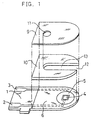
- FIG. 1 shows an exploded perspective view of a two-electrode system glucose sensor with an omission of the reaction layer.
- a silver paste is printed on an electrically insulating base plate 1 of polyethylene terephthalate by the screen printing method so as to form leads 2 and 3 on the base plate 1.
- a conductive carbon paste containing a resin binder is printed on the base plate 1 so as to form a working electrode 4.
- the working electrode 4 is in contact with the lead 2.
- an electrically insulating layer 6 is further formed on the base plate 1 by printing thereon an insulating paste.
- the electrically insulating layer 6 covers the periphery of the working electrode 4 so as to hold the exposed area of the working electrode 4 constant.
- a conductive carbon paste containing a resin binder and a redox compound or an electrolytically oxidizable metal, or a silver or copper paste including a resin binder is printed on the base plate 1 so as to cause the paste to contact the previously formed lead 3, which formed a ring-like counter electrode 5.
- the electrically insulating base plate 1, a cover 9 having an air vent 11 and a spacer 10 are bonded to each other in a positional relationship as shown by the dotted chain line in FIG. 1, which gives a biosensor used as a glucose sensor in the below-mentioned examples.
- the spacer 10 has a slit 13 for forming a sample supply path between the base plate and the cover.
- Numeral 12 corresponds to an opening of the sample supply path.
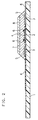
- FIG. 2 is a vertical cross-sectional view illustrating vital parts of the biosensor in accordance with the present invention from which the spacer and the cover are omitted.
- a reaction layer 7 containing reagents including an enzyme and an electron mediator is formed, above which a lecithin layer 8 is further formed later.
- the reaction layer 7 is preferably formed on the electrode system, but it may be formed in the vicinity of the electrode system, for instance, on the cover side so as to be exposed to the sample supply path.
- an electrode system having at least a counter electrode of a conductive carbon paste that includes a resin binder and ferrocene as the redox compound was formed first.
- reaction layer 7 was formed by dropping a mixed aqueous solution of glucose oxidase (EC1.1.3.4; hereinafter referred to as "GOD") with potassium ferricyanide on the electrode system and drying it.
- glucose oxidase EC1.1.3.4
- lecithin layer 8 was formed by dropping a toluene solution of lecithin on the reaction layer 7 and drying it.
- the cover 9 and the spacer 10 were then bonded to the base plate 1 in a positional relationship shown by the dotted chain line in FIG. 1, which gave a glucose sensor used in this example.
- an aqueous glucose standard solution (3 ⁇ l) was supplied to the glucose sensor through the opening 12 of the sample supply path.
- the sample solution advanced to the air vent 11 and dissolved the reaction layer 7 present above the electrode system.
- enzyme reaction where glucose contained in the sample solution is oxidized to gluconolactone by the GOD will take place. This enzyme reaction accompanies at the same time reduction of the ferricyanide ions to ferrocyanide ions.
- the current values measured using various aqueous standard solutions at different glucose concentrations showed decreases with increases in the glucose concentration. This implies that the presence of ferrocene in the counter electrode secured a sufficient amount of a reductant in the reaction system and that the current values depended on the amount of ferricyanide ions to be reduced to ferrocyanide ions on the working electrode.
- the responsive current value measured with the glucose sensor showed high accuracy.
- CMC carboxymethyl cellulose
- a glucose sensor was produced in the same manner as in Example 1 to measure the sensor responses to various glucose standard solutions. The results showed similar response characteristics for the glucose sensor of this example to those of Example 1, demonstrating less variations.
- the responsive current value of the glucose sensor was measured in the same manner as in Example 2, except for the use of various aqueous glucose standard solutions containing known amounts of ascorbic acid as the sample solutions.
- Example 2 The results showed that the glucose sensor had similar response characteristics to those of Example 2 which used mere aqueous glucose standard solutions with no ascorbic acid.
- a glucose sensor was produced in the same manner as in Example 2 except for the use of vinyl ferrocene as the redox compound and measured for its responses to the aqueous glucose standard solutions.
- the glucose sensor of Example 4 demonstrated similar response characteristics to those of Example 2.
- a glucose sensor was produced in the same manner as in Example 1 except for the use of a silver paste to form the counter electrode 5 shown in FIG. 1.
- an aqueous glucose standard solution (3 ⁇ l) as a sample solution was supplied to the glucose sensor through the opening 12 of the sample supply path.
- the sample solution advanced to the air vent 11 and dissolved the reaction layer 7 present above the electrode system.
- enzyme reaction where glucose contained in the sample solution is oxidized to gluconolactone by the GOD will take place. This enzyme reaction accompanies at the same time reduction of the ferricyanide ions to ferrocyanide ions.
- a glucose sensor was produced in the same manner as in Example 5 except for the use of a copper paste in place of silver paste to form the counter electrode 5 and measured for its responses to various aqueous glucose standard solutions.
- the glucose sensor of this example showed similar response characteristics to those of Example 5.
- Example 7 Another glucose sensor was produced in the same manner as in Example 5 except for the use of a mixed paste of silver and carbon to form the counter electrode and measured for its responses to various aqueous glucose standard solutions.
- the glucose sensor of Example 7 showed similar response characteristics to those of Example 5.
- the responsive current value of the glucose sensor of Example 5 was measured in the same manner as in Example 5, except for the use of various aqueous glucose standard solutions containing known amounts of ascorbic acid as the sample solutions.
- Example 8 As a comparative example, the same glucose sensor as in Example 5 and various aqueous glucose standard solutions containing ascorbic acid as in Example 8 were used. The glucose sensor was applied with a voltage of 0.5 V to the working electrode using the counter electrode as reference and the oxidation current value flowing across the electrodes was measured after 5 seconds. The results showed increased responsive current values with the increases in the ascorbic acid concentration in the aqueous glucose standard solution.
Abstract
Description
- The present invention relates to a biosensor for facilitating simple and high accuracy quantitation of a substrate and a method for quantitative measurement of a substrate using the same.
- There has been a conventional simple method for quantitating a specific component in a sample solution with no dilution or agitation of the sample solution. This method causes the specific component to react with an oxidoreductase whose substrate corresponds to the specific component in the presence of an electron mediator or electron acceptor and subsequently oxidizes the electron mediator reduced by the enzyme reaction electrochemically. The concentration of the specific component is then determined from the oxidation current flowing during this electrochemical oxidation.
- This method normally uses a biosensor as disclosed in Japanese Laid-Open Patent Publication No. 2,517,153.
- The biosensor is produced by first forming an electrode system having a working electrode and a counter electrode on an electrically insulating base plate by a screen printing method or the like, subsequently forming a reaction layer including an oxidoreductase and an electron mediator on the electrode system, and finally bonding a cover and a spacer to the electrically insulating base plate.
- This biosensor facilitates quantitation of various specific components by varying the oxidoreductase.
- A glucose sensor will be described as an example of biosensor.
- Conventionally known method for quantitative measurement of glucose is a system comprising a combination of glucose oxidase with an oxygen electrode or a hydrogen peroxide electrode (e.g., "Biosensor", ed. by Shuichi Suzuki, Kodansha, Japan).
- Glucose oxidase selectively oxidizes a substrate β-D-glucose to D-glucono-δ-lactone by utilizing oxygen dissolved in a sample solution as an electron mediator. When the substrate is oxidized by the glucose oxidase, the oxygen used as the electron mediator is reduced to hydrogen peroxide. The glucose concentration can be quantitated either by measurement of the volume of oxygen consumed during this reaction using an oxygen electrode or by measurement of the volume of hydrogen peroxide produced using a hydrogen peroxide electrode of platinum or the like.
- However, this method has a drawback that the measurement is largely affected by the concentration of oxygen contained in a sample solution, depending on the measuring object. This system has another drawback that the system cannot function in the absence of oxygen.
- To overcome these problems, a type of glucose sensor has been developed which includes an organic compound or a metal complex such as potassium ferricyanide, ferrocene derivatives, quinone derivatives, etc. as electron mediator, in place of oxygen.
- This biosensor can carry a known amount of glucose oxidase on an electrode system, together with an electron mediator in their stabilized state. This structure enables to combine the electrode system with the reaction layer integrally almost in dry state.
- Such biosensor is normally disposable and facilitates measurement of the concentration of glucose by a simple instillation of a measuring sample at a sensor chip mounted in a measurement device. Therefore, this biosensor has been attracting much attention recently.
- As described above, the substrate in a sample can be quantitated based on the current required for oxidizing the reductant of the electron mediator which has been produced by a series of enzyme reaction on the electrode.
- However, some samples are assumed to contain an easy-to-oxidize substance which is oxidized upon oxidation of an electron mediator in reduced state on the electrode to generate an oxidation current and hence produces a positive error in the current value measured. Moreover, if the measuring sample contains a high concentration of substrate, the oxidation current value may vary.
- In order to solve these problems, the present inventors propose a method for quantitative measurement of a substrate based on the reduction current value which flows during reduction of the electron mediator in oxidized state on the working electrode which remains not reduced by a series of enzyme reaction. This method precludes adverse effects of any easy-to-oxidize substance on the measurement results.
- However, if the reduction current value is measured with a two-electrode system comprising a working electrode and a counter electrode, then the presence of some amount of electron mediator in reduced state which must be oxidized on the counter electrode in correspondence with the reduction of already oxidized electron mediator on the working electrode becomes mandatory. With this system, however, if the substrate concentration is predicted to be low, the electron mediator in reduced state may be depleted, which renders the oxidation on the counter electrode to develop a rate-determining step that adversely affects the reduction current value measured.
- The object of the present invention is therefore to provide a biosensor facilitating high accuracy quantitation of a substrate concentration in a sample by eliminating the above-mentioned inconveniences.
- Another object of the present invention is to provide a method for simple and high performance quantitative measurement of a substrate with high accuracy with the aid of this biosensor.
- The present invention provides a biosensor comprising an electrically insulating base plate, an electrode system having a working electrode and a counter electrode formed on the base plate, and a reaction layer which is formed on or in the vicinity of the electrode system and contains at least an oxidoreductase and an electron mediator, wherein the counter electrode includes at least a reductant of a redox compound or a metal permitting electrolytic oxidation.
- The present invention also provides a method for quantitative measurement of a substrate by using the above-mentioned biosensor, comprising a first step of adding a sample to the reaction layer to cause a substrate contained in the sample to react with an enzyme contained in the reaction layer, a second step of applying a potential to the working electrode for reducing the electron mediator in oxidized state that remains not reduced in the course of the first step, and a third step of measuring a reduction current flowing across the working electrode and the counter electrode.
- In a preferred mode of the invention, the counter electrode includes ferrocene or a ferrocene derivative as the redox compound.
- In another preferred mode of the invention, the counter electrode includes silver or copper as the electrolytically oxidizable metal.
- In still another preferred mode of the invention, the counter electrode is composed of a mixture of at least an electrolytically oxidizable metal with carbon.
- While the novel features of the invention are set forth particularly in the appended claims, the invention, both as to organization and content, will be better understood and appreciated, along with other objects and features thereof, from the following detailed description taken in conjunction with the drawings.
-
- FIG. 1 is an exploded perspective view of a glucose sensor with an omission of the reaction layer in one example of the present invention.
- FIG. 2 is a vertical cross-sectional view illustrating the vital part of the glucose sensor with an omission of the spacer and the cover.
-
- As stated above, the method for quantitative measurement of a substrate in accordance with the present invention adds a sample to the reaction layer to cause the substrate to react with the enzyme. As the enzyme reaction proceeds, the electron mediator contained in the reaction layer is reduced to the extent to reflect the concentration of substrate in the sample. Then, a potential is applied to the working electrode to reduce the electron mediator in oxidized state which remains not reduced during the enzyme reaction thereby to generate reduction current. The substrate concentration is then determined by measuring the reduction current flowing across the two electrodes.
- In this method, if the amount of electron mediator is held at a constant level in the reaction layer, the reduction current reflects the concentration of substrate in the sample sharply. Therefore, if a reduction current value of a standard solution containing a known amount of substrate is calibrated preliminarily to obtain a reference calibration curve, the substrate concentration in a sample can be quantitatively determined based on the reference.
- As such, the present invention quantifies a substrate based on the reduction current, which prevents the reduction current from being adversely affected by, if any, the presence of an easy-to-oxidize substance.
- Furthermore, as described above, the counter electrode includes at least a reductant of a redox compound or an electrolytically oxidizable metal. This configuration prevents the oxidation on the counter electrode from entering the rate-determining step in the course of measurement of reduction current values on the working electrode, even if the sample contains a low concentration of substrate and hence the available electron mediator in reduced state generating by the enzyme reaction is small in amount.
- The biosensor in accordance with the present invention includes an improved counter electrode, which precludes a concern about influences of the counter electrode on sensor preservation. Certain redox compounds may have adverse effects on the sensor preservation; therefore, if a redox compound is to be added to the enzyme layer, it is essential to examine its effect preliminarily. The present invention includes a reductant of a redox compound or an electrolytically oxidizable metal in the counter electrode, which configuration produces an advantage that they can be added in a larger amount if the substrate concentration is high, compared to a biosensor which adds those components in the reaction layer.
- It is better that the amount of redox compound or electrolytically oxidizable metal to be contained in the counter electrode is larger than the amount of electron mediator to be contained in the reaction layer.
- Preferably used redox compounds may be exemplified as ferrocene, a ferrocene derivative such as vinyl ferrocene, a metal complex, hydroquinone, etc.
- On the other hand, preferred electrolytically oxidizable metal includes silver and copper, but iron, zinc and the like may also be used.
- This metal can be ground into a powder and mixed with a binder to make a paste for use in the counter electrode by printing the paste directly on a base plate. This simplifies the manufacturing process of a sensor.
- A counter electrode comprising a mixture of a powder of the metal with a carbon powder and a binder can reduce the production cost, which is preferable.
- It is also preferable to coat the entire surface of the electrode system formed on the base plate with a layer of a hydrophilic polymer so as to avoid possible contact of the enzyme and electron mediator in the reaction layer or possible adsorption of protein in the sample with or onto the surface of the electrode system.
- Available hydrophilic polymers for forming the hydrophilic polymer layer include polyvinyl pyrrolidone, polyvinyl alcohol, polyamino acid such as polylysine, polystyrene sulfonate, gelatin and its derivative, a polymer of acrylic acid or an acrylate, a polymer of methacrylic acid or a methacrylate, starch and its derivative, a polymer of maleic anhydride or a maleate, cellulose derivatives such as carboxymethyl cellulose, hydroxypropyl cellulose, methyl cellulose, ethyl cellulose, hydroxyethyl cellulose, ethylhydroxyethyl cellulose, carboxymethylethyl cellulose or the like. Among them, carboxymethyl cellulose, hydroxyethyl cellulose, hydroxypropyl cellulose, methyl cellulose, ethyl cellulose, ethylhydroxyethyl cellulose and carboxymethylethyl cellulose are preferred.
- As the electron mediator to be contained in the reaction layer, potassium ferricyanide, p-benzoquinone, phenazine methosulfate, methylene blue, ferrocene derivatives, or the like may be used.
- Applicable oxidoreductases include glucose oxidase, glucose dehydrogenase, alcohol oxidase, lactate oxidase, lactate dehydrogenase, fructose dehydrogenase, uricase, cholesterol oxidase, cholesterol esterase, xanthine oxidase, amino acid oxidase and the like.
- A combination of plural oxidoreductases may also be used, for example, glucose oxidase plus invertase, glucose oxidase plus invertase plus mutarotase, fructose dehydrogenase plus invertase, or the like.
- The enzyme and the electron mediator may be dissolved in the sample solution, or prevented from being dissolved in the sample solution by fixing the reaction layer to the base plate. If the latter configuration is adopted, it is preferred for the reaction layer to further contain one of the hydrophilic polymers exemplified above.
- The reaction layer may further contain a pH buffer. The pH buffer may be exemplified as potassium dihydrogen phosphate-dipotassium phosphate, potassium dihydrogen phosphate-disodium phosphate, sodium dihydrogen phosphate-dipotassium phosphate, sodium dihydrogen phosphate-disodium phosphate, citric acid-disodium phosphate, citric acid-dipotassium phosphate, citric acid-trisodium citrate, citric acid-tripotassium citrate, potassium dihydrogen citrate-sodium hydroxide, sodium dihydrogen citrate-sodium hydroxide, sodium hydrogen maleate-sodium hydroxide, potassium hydrogen phthalate-sodium hydroxide, succinic acid-sodium tetraborate, maleic acid-tris(hydroxymethyl)aminomethane, tris(hydroxymethyl)aminomethane-tris(hydroxymethyl)aminoethane hydrochloride, [N-(2-hydroxyethyl)piperazine-N'-2-ethanesulfonic acid]-sodium hydroxide, [N-tris(hydroxymethyl)methyl-2-aminoethanesulfonic acid]-sodium hydroxide, and [piperazine-N,N'-bis(2-ethanesulfonic acid)]-sodium hydroxide.
- A lecithin layer may also be formed on the reaction layer for smooth supply of a sample solution.
- In the following, the present invention will be described specifically by way of concrete examples.
- In the below-mentioned examples, although the working electrode, the counter electrode and the insulating layer were formed by specific printing patterns, the present invention is not limited to those patterns. Similarly, the voltage to be applied to the electrode is not limited to that used in the below-mentioned examples.
- FIG. 1 shows an exploded perspective view of a two-electrode system glucose sensor with an omission of the reaction layer. In the glucose sensor, a silver paste is printed on an electrically insulating
base plate 1 of polyethylene terephthalate by the screen printing method so as to form leads 2 and 3 on thebase plate 1. Subsequently, a conductive carbon paste containing a resin binder is printed on thebase plate 1 so as to form a workingelectrode 4. The workingelectrode 4 is in contact with thelead 2. Then, an electrically insulatinglayer 6 is further formed on thebase plate 1 by printing thereon an insulating paste. The electrically insulatinglayer 6 covers the periphery of the workingelectrode 4 so as to hold the exposed area of the workingelectrode 4 constant. Thereafter, a conductive carbon paste containing a resin binder and a redox compound or an electrolytically oxidizable metal, or a silver or copper paste including a resin binder is printed on thebase plate 1 so as to cause the paste to contact the previously formedlead 3, which formed a ring-like counter electrode 5. - Then, the electrically insulating
base plate 1, acover 9 having an air vent 11 and aspacer 10 are bonded to each other in a positional relationship as shown by the dotted chain line in FIG. 1, which gives a biosensor used as a glucose sensor in the below-mentioned examples. Thespacer 10 has aslit 13 for forming a sample supply path between the base plate and the cover.Numeral 12 corresponds to an opening of the sample supply path. - FIG. 2 is a vertical cross-sectional view illustrating vital parts of the biosensor in accordance with the present invention from which the spacer and the cover are omitted. On the electrically insulating
base plate 1 on which the electrode system is already formed as shown in FIG. 1, a reaction layer 7 containing reagents including an enzyme and an electron mediator is formed, above which alecithin layer 8 is further formed later. - The reaction layer 7 is preferably formed on the electrode system, but it may be formed in the vicinity of the electrode system, for instance, on the cover side so as to be exposed to the sample supply path.
- As shown in FIG. 1, on the
base plate 1, an electrode system having at least a counter electrode of a conductive carbon paste that includes a resin binder and ferrocene as the redox compound was formed first. - Then, the reaction layer 7 was formed by dropping a mixed aqueous solution of glucose oxidase (EC1.1.3.4; hereinafter referred to as "GOD") with potassium ferricyanide on the electrode system and drying it. Subsequently, the
lecithin layer 8 was formed by dropping a toluene solution of lecithin on the reaction layer 7 and drying it. - The
cover 9 and thespacer 10 were then bonded to thebase plate 1 in a positional relationship shown by the dotted chain line in FIG. 1, which gave a glucose sensor used in this example. - As a sample solution, an aqueous glucose standard solution (3 µl) was supplied to the glucose sensor through the
opening 12 of the sample supply path. The sample solution advanced to the air vent 11 and dissolved the reaction layer 7 present above the electrode system. Upon dissolution of the reaction layer 7, enzyme reaction where glucose contained in the sample solution is oxidized to gluconolactone by the GOD will take place. This enzyme reaction accompanies at the same time reduction of the ferricyanide ions to ferrocyanide ions. - When a certain time had lapsed after supply of the sample solution, a voltage of -1.0 V was applied to the working
electrode 4 with reference to the counter electrode 5, which induced reduction of the potassium ferricyanide which was refractory to the reduction caused by the enzyme reaction on the working electrode. On the counter electrode, on the other hand, oxidation of ferrocene contained in the counter electrode will take place to produce ferricinium ions. The reduction current value flowing across the electrodes was measured 5 seconds after application of the voltage. - The current values measured using various aqueous standard solutions at different glucose concentrations showed decreases with increases in the glucose concentration. This implies that the presence of ferrocene in the counter electrode secured a sufficient amount of a reductant in the reaction system and that the current values depended on the amount of ferricyanide ions to be reduced to ferrocyanide ions on the working electrode. The responsive current value measured with the glucose sensor showed high accuracy.
- In this example, an aqueous solution of carboxymethyl cellulose (hereinafter abbreviated to "CMC") was dropped on the electrode system identical to that of Example 1 and dried to form a CMC layer. The reaction layer and the lecithin layer were formed in this order on the CMC layer in the same manner as in Example 1.
- A glucose sensor was produced in the same manner as in Example 1 to measure the sensor responses to various glucose standard solutions. The results showed similar response characteristics for the glucose sensor of this example to those of Example 1, demonstrating less variations.
- In this example, the responsive current value of the glucose sensor was measured in the same manner as in Example 2, except for the use of various aqueous glucose standard solutions containing known amounts of ascorbic acid as the sample solutions.
- The results showed that the glucose sensor had similar response characteristics to those of Example 2 which used mere aqueous glucose standard solutions with no ascorbic acid.
- As a comparative example, identical glucose sensor and aqueous glucose standard solutions containing ascorbic acid to those of Example 3 were used to measure oxidation current values flowing 5 seconds after application of a voltage of 0.5 V to the working electrode using the counter electrode as reference.
- The results showed that the responsive current values were elevated as the amount of ascorbic acid contained in the aqueous glucose standard solution increased.
- A glucose sensor was produced in the same manner as in Example 2 except for the use of vinyl ferrocene as the redox compound and measured for its responses to the aqueous glucose standard solutions. The glucose sensor of Example 4 demonstrated similar response characteristics to those of Example 2.
- A glucose sensor was produced in the same manner as in Example 1 except for the use of a silver paste to form the counter electrode 5 shown in FIG. 1.
- Similar to Example 1, an aqueous glucose standard solution (3 µl) as a sample solution was supplied to the glucose sensor through the
opening 12 of the sample supply path. The sample solution advanced to the air vent 11 and dissolved the reaction layer 7 present above the electrode system. Upon dissolution of the reaction layer 7, enzyme reaction where glucose contained in the sample solution is oxidized to gluconolactone by the GOD will take place. This enzyme reaction accompanies at the same time reduction of the ferricyanide ions to ferrocyanide ions. - When a certain time had lapsed after supply of the sample solution, a voltage of -0.8 V was applied to the working
electrode 4 with reference to the counter electrode 5, which induced reduction of the ferricyanide ions which remained not reduced by the enzyme reaction on the working electrode to generate ferrocyanide ions. On the counter electrode, on the other hand, oxidation of silver contained in the counter electrode will take place to produce silver ions. The reduction current value flowing across the electrodes was measured 5 seconds after application of the voltage. The current values measured using various aqueous glucose standard solutions showed decreases with increases in the glucose concentration. This implies that the presence of silver in the counter electrode secured a sufficient amount of a reductant in the reaction system and that the current values depended on the amount of ferricyanide ions to be reduced to ferrocyanide ions on the working electrode. The responsive current value measured with the glucose sensor showed high accuracy. - A glucose sensor was produced in the same manner as in Example 5 except for the use of a copper paste in place of silver paste to form the counter electrode 5 and measured for its responses to various aqueous glucose standard solutions. The glucose sensor of this example showed similar response characteristics to those of Example 5.
- Another glucose sensor was produced in the same manner as in Example 5 except for the use of a mixed paste of silver and carbon to form the counter electrode and measured for its responses to various aqueous glucose standard solutions. The glucose sensor of Example 7 showed similar response characteristics to those of Example 5.
- In this example, the responsive current value of the glucose sensor of Example 5 was measured in the same manner as in Example 5, except for the use of various aqueous glucose standard solutions containing known amounts of ascorbic acid as the sample solutions.
- The results showed identical response characteristics for the glucose sensor of Example 8 to those of Example 5 which used mere aqueous glucose standard solutions with no ascorbic acid.
- As a comparative example, the same glucose sensor as in Example 5 and various aqueous glucose standard solutions containing ascorbic acid as in Example 8 were used. The glucose sensor was applied with a voltage of 0.5 V to the working electrode using the counter electrode as reference and the oxidation current value flowing across the electrodes was measured after 5 seconds. The results showed increased responsive current values with the increases in the ascorbic acid concentration in the aqueous glucose standard solution.
- Although the present invention has been described in terms of the presently preferred embodiments, it is to be understood that such disclosure is not to be interpreted as limiting. Various alterations and modifications will no doubt become apparent to those skilled in the art to which the present invention pertains, after having read the above disclosure. Accordingly, it is intended that the appended claims be interpreted as covering all alterations and modifications as fall within the true spirit and scope of the invention.
Claims (6)
- A biosensor comprising an electrically insulating base plate, an electrode system having a working electrode and a counter electrode formed on said base plate, and a reaction layer which is formed on or in the vicinity of said electrode system and contains at least an oxidoreductase and an electron mediator, said counter electrode including at least a reductant of a redox compound or a metal permitting electrolytic oxidation.
- The biosensor in accordance with claim 1, wherein said redox compound is ferrocene or a ferrocene derivative.
- The biosensor in accordance with claim 1, wherein said counter electrode is composed of a mixture of at least one electrolytically oxidizable metal with carbon.
- The biosensor in accordance with claim 1, wherein said electrolytically oxidizable metal is silver or copper.
- The biosensor in accordance with claim 1, wherein said reaction layer further contains a hydrophilic polymer.
- A method for quantitative measurement of a substrate by using a biosensor which comprises an electrically insulating base plate, an electrode system having a working electrode and a counter electrode including at least a reductant of a redox compound and an electrically oxidizable metal, both being formed on said base plate, and a reaction layer which is formed on or in the vicinity of said electrode system and contains at least an oxidoreductase and an electron mediator, said method comprising:a first step of adding a sample to said reaction layer to cause a substrate contained in said sample to react with an enzyme contained in said reaction layer,a second step of applying a potential to said working electrode for reducing said electron mediator in oxidized state that remains not reduced in the course of said first step, anda third step of measuring a reduction current flowing across said working electrode and said counter electrode.
Applications Claiming Priority (6)
| Application Number | Priority Date | Filing Date | Title |
|---|---|---|---|
| JP26349297A JP3267907B2 (en) | 1997-09-29 | 1997-09-29 | Biosensor and Substrate Quantification Method Using It |
| JP26349297 | 1997-09-29 | ||
| JP26348397A JP3245103B2 (en) | 1997-09-29 | 1997-09-29 | Biosensor and Substrate Quantification Method Using It |
| JP263492/97 | 1997-09-29 | ||
| JP263483/97 | 1997-09-29 | ||
| JP26348397 | 1997-09-29 |
Publications (3)
| Publication Number | Publication Date |
|---|---|
| EP0909952A2 true EP0909952A2 (en) | 1999-04-21 |
| EP0909952A3 EP0909952A3 (en) | 2000-08-30 |
| EP0909952B1 EP0909952B1 (en) | 2005-11-30 |
Family
ID=26546032
Family Applications (1)
| Application Number | Title | Priority Date | Filing Date |
|---|---|---|---|
| EP98118218A Expired - Lifetime EP0909952B1 (en) | 1997-09-29 | 1998-09-25 | Biosensor and method for quantitative measurement of a substrate using the same |
Country Status (4)
| Country | Link |
|---|---|
| US (1) | US5906921A (en) |
| EP (1) | EP0909952B1 (en) |
| CN (1) | CN1163743C (en) |
| DE (1) | DE69832572T2 (en) |
Cited By (21)
| Publication number | Priority date | Publication date | Assignee | Title |
|---|---|---|---|---|
| EP1065501A1 (en) * | 1998-02-26 | 2001-01-03 | Kyoto Daiichi Kagaku Co., Ltd. | Blood measuring instrument |
| EP1124131A2 (en) * | 2000-01-27 | 2001-08-16 | Matsushita Electric Industrial Co., Ltd. | Biosensor and method of producing the same |
| DE10032042A1 (en) * | 2000-07-05 | 2002-01-24 | Inventus Biotec Gesellschaft Fuer Innovative Bioanalytik, Biosensoren Und Diagnostika Mbh & Co. Kg | Disposable electrochemical biosensor for the quantitative determination of analyte concentrations in liquids |
| GB2365123A (en) * | 2000-07-20 | 2002-02-13 | Hypoguard Ltd | Test strip |
| WO2002054055A1 (en) * | 2001-01-04 | 2002-07-11 | Tyson Bioresearch, Inc. | Biosensors having improved sample application |
| WO2002097419A1 (en) * | 2001-05-31 | 2002-12-05 | Instrumentation Laboratory Company | Cross-linked enzyme matrix and uses thereof |
| WO2003087801A1 (en) * | 2002-04-09 | 2003-10-23 | University Of Warwick | Biosensor for purines |
| US6652720B1 (en) | 2001-05-31 | 2003-11-25 | Instrumentation Laboratory Company | Analytical instruments, biosensors and methods thereof |
| US6827899B2 (en) | 2000-08-30 | 2004-12-07 | Hypoguard Limited | Test device |
| US6872297B2 (en) | 2001-05-31 | 2005-03-29 | Instrumentation Laboratory Company | Analytical instruments, biosensors and methods thereof |
| WO2005040407A1 (en) * | 2003-10-24 | 2005-05-06 | Bayer Healthcare Llc | Enzymatic electrochemical biosensor |
| US6896793B2 (en) | 2001-03-07 | 2005-05-24 | Instrumentation Laboratory Company | Liquid junction reference electrode and methods of use thereof |
| US6982027B2 (en) | 2000-10-27 | 2006-01-03 | Arkray, Inc. | Biosensor |
| US7118667B2 (en) | 2004-06-02 | 2006-10-10 | Jin Po Lee | Biosensors having improved sample application and uses thereof |
| US7138089B2 (en) | 2000-07-20 | 2006-11-21 | Hypoguard Limited | Test device for analyzing blood glucose or other analytes in bodily fluids |
| US7416699B2 (en) | 1998-08-14 | 2008-08-26 | The Board Of Trustees Of The Leland Stanford Junior University | Carbon nanotube devices |
| US7422903B2 (en) | 2002-12-11 | 2008-09-09 | Instrumentation Laboratory Company | Multi-analyte reference solutions |
| US8137529B2 (en) | 2004-02-06 | 2012-03-20 | Bayer Healthcare Llc | Methods of using an electrochemical biosensor |
| USRE44521E1 (en) | 1999-08-02 | 2013-10-08 | Bayer Healthcare Llc | Electrochemical-sensor design |
| US8550295B2 (en) | 2010-02-22 | 2013-10-08 | Roche Diagnostics Operations, Inc. | Container for dispensing a single test strip |
| EP1074832B2 (en) † | 1999-08-02 | 2014-08-13 | Bayer HealthCare LLC | Improved electrochemical-sensor design |
Families Citing this family (98)
| Publication number | Priority date | Publication date | Assignee | Title |
|---|---|---|---|---|
| DE69809391T2 (en) | 1997-02-06 | 2003-07-10 | Therasense Inc | SMALL VOLUME SENSOR FOR IN-VITRO DETERMINATION |
| US6036924A (en) | 1997-12-04 | 2000-03-14 | Hewlett-Packard Company | Cassette of lancet cartridges for sampling blood |
| US6103033A (en) | 1998-03-04 | 2000-08-15 | Therasense, Inc. | Process for producing an electrochemical biosensor |
| US6391005B1 (en) | 1998-03-30 | 2002-05-21 | Agilent Technologies, Inc. | Apparatus and method for penetration with shaft having a sensor for sensing penetration depth |
| US6294281B1 (en) * | 1998-06-17 | 2001-09-25 | Therasense, Inc. | Biological fuel cell and method |
| JP3267936B2 (en) * | 1998-08-26 | 2002-03-25 | 松下電器産業株式会社 | Biosensor |
| US6338790B1 (en) | 1998-10-08 | 2002-01-15 | Therasense, Inc. | Small volume in vitro analyte sensor with diffusible or non-leachable redox mediator |
| US7045054B1 (en) * | 1999-09-20 | 2006-05-16 | Roche Diagnostics Corporation | Small volume biosensor for continuous analyte monitoring |
| US8641644B2 (en) | 2000-11-21 | 2014-02-04 | Sanofi-Aventis Deutschland Gmbh | Blood testing apparatus having a rotatable cartridge with multiple lancing elements and testing means |
| US6887667B2 (en) * | 2000-12-28 | 2005-05-03 | Alfred E. Mann Institute For Biomedical Engineering At The University Of Southern California | Method and apparatus to identify small variations of biomolecules |
| US7005273B2 (en) * | 2001-05-16 | 2006-02-28 | Therasense, Inc. | Method for the determination of glycated hemoglobin |
| US9226699B2 (en) | 2002-04-19 | 2016-01-05 | Sanofi-Aventis Deutschland Gmbh | Body fluid sampling module with a continuous compression tissue interface surface |
| US7981056B2 (en) | 2002-04-19 | 2011-07-19 | Pelikan Technologies, Inc. | Methods and apparatus for lancet actuation |
| US9427532B2 (en) | 2001-06-12 | 2016-08-30 | Sanofi-Aventis Deutschland Gmbh | Tissue penetration device |
| US8337419B2 (en) | 2002-04-19 | 2012-12-25 | Sanofi-Aventis Deutschland Gmbh | Tissue penetration device |
| ATE485766T1 (en) | 2001-06-12 | 2010-11-15 | Pelikan Technologies Inc | ELECTRICAL ACTUATING ELEMENT FOR A LANCET |
| DE60234598D1 (en) | 2001-06-12 | 2010-01-14 | Pelikan Technologies Inc | SELF-OPTIMIZING LANZET DEVICE WITH ADAPTANT FOR TEMPORAL FLUCTUATIONS OF SKIN PROPERTIES |
| US9795747B2 (en) | 2010-06-02 | 2017-10-24 | Sanofi-Aventis Deutschland Gmbh | Methods and apparatus for lancet actuation |
| US7749174B2 (en) | 2001-06-12 | 2010-07-06 | Pelikan Technologies, Inc. | Method and apparatus for lancet launching device intergrated onto a blood-sampling cartridge |
| EP1404234B1 (en) | 2001-06-12 | 2011-02-09 | Pelikan Technologies Inc. | Apparatus for improving success rate of blood yield from a fingerstick |
| US7682318B2 (en) | 2001-06-12 | 2010-03-23 | Pelikan Technologies, Inc. | Blood sampling apparatus and method |
| US7025774B2 (en) | 2001-06-12 | 2006-04-11 | Pelikan Technologies, Inc. | Tissue penetration device |
| US7052591B2 (en) * | 2001-09-21 | 2006-05-30 | Therasense, Inc. | Electrodeposition of redox polymers and co-electrodeposition of enzymes by coordinative crosslinking |
| US20030119203A1 (en) | 2001-12-24 | 2003-06-26 | Kimberly-Clark Worldwide, Inc. | Lateral flow assay devices and methods for conducting assays |
| US8367013B2 (en) * | 2001-12-24 | 2013-02-05 | Kimberly-Clark Worldwide, Inc. | Reading device, method, and system for conducting lateral flow assays |
| US8267870B2 (en) | 2002-04-19 | 2012-09-18 | Sanofi-Aventis Deutschland Gmbh | Method and apparatus for body fluid sampling with hybrid actuation |
| US8221334B2 (en) | 2002-04-19 | 2012-07-17 | Sanofi-Aventis Deutschland Gmbh | Method and apparatus for penetrating tissue |
| US9314194B2 (en) | 2002-04-19 | 2016-04-19 | Sanofi-Aventis Deutschland Gmbh | Tissue penetration device |
| US8784335B2 (en) | 2002-04-19 | 2014-07-22 | Sanofi-Aventis Deutschland Gmbh | Body fluid sampling device with a capacitive sensor |
| US7674232B2 (en) | 2002-04-19 | 2010-03-09 | Pelikan Technologies, Inc. | Method and apparatus for penetrating tissue |
| US7648468B2 (en) | 2002-04-19 | 2010-01-19 | Pelikon Technologies, Inc. | Method and apparatus for penetrating tissue |
| US7226461B2 (en) | 2002-04-19 | 2007-06-05 | Pelikan Technologies, Inc. | Method and apparatus for a multi-use body fluid sampling device with sterility barrier release |
| US8579831B2 (en) | 2002-04-19 | 2013-11-12 | Sanofi-Aventis Deutschland Gmbh | Method and apparatus for penetrating tissue |
| US7892183B2 (en) | 2002-04-19 | 2011-02-22 | Pelikan Technologies, Inc. | Method and apparatus for body fluid sampling and analyte sensing |
| US7717863B2 (en) | 2002-04-19 | 2010-05-18 | Pelikan Technologies, Inc. | Method and apparatus for penetrating tissue |
| US7291117B2 (en) | 2002-04-19 | 2007-11-06 | Pelikan Technologies, Inc. | Method and apparatus for penetrating tissue |
| US7901362B2 (en) | 2002-04-19 | 2011-03-08 | Pelikan Technologies, Inc. | Method and apparatus for penetrating tissue |
| US8702624B2 (en) | 2006-09-29 | 2014-04-22 | Sanofi-Aventis Deutschland Gmbh | Analyte measurement device with a single shot actuator |
| US7229458B2 (en) | 2002-04-19 | 2007-06-12 | Pelikan Technologies, Inc. | Method and apparatus for penetrating tissue |
| US7547287B2 (en) | 2002-04-19 | 2009-06-16 | Pelikan Technologies, Inc. | Method and apparatus for penetrating tissue |
| US7371247B2 (en) | 2002-04-19 | 2008-05-13 | Pelikan Technologies, Inc | Method and apparatus for penetrating tissue |
| US8360992B2 (en) | 2002-04-19 | 2013-01-29 | Sanofi-Aventis Deutschland Gmbh | Method and apparatus for penetrating tissue |
| US7491178B2 (en) | 2002-04-19 | 2009-02-17 | Pelikan Technologies, Inc. | Method and apparatus for penetrating tissue |
| US7175642B2 (en) | 2002-04-19 | 2007-02-13 | Pelikan Technologies, Inc. | Methods and apparatus for lancet actuation |
| US7892185B2 (en) | 2002-04-19 | 2011-02-22 | Pelikan Technologies, Inc. | Method and apparatus for body fluid sampling and analyte sensing |
| US7909778B2 (en) * | 2002-04-19 | 2011-03-22 | Pelikan Technologies, Inc. | Method and apparatus for penetrating tissue |
| US7976476B2 (en) | 2002-04-19 | 2011-07-12 | Pelikan Technologies, Inc. | Device and method for variable speed lancet |
| US9795334B2 (en) | 2002-04-19 | 2017-10-24 | Sanofi-Aventis Deutschland Gmbh | Method and apparatus for penetrating tissue |
| US7331931B2 (en) | 2002-04-19 | 2008-02-19 | Pelikan Technologies, Inc. | Method and apparatus for penetrating tissue |
| US7297122B2 (en) | 2002-04-19 | 2007-11-20 | Pelikan Technologies, Inc. | Method and apparatus for penetrating tissue |
| US9248267B2 (en) | 2002-04-19 | 2016-02-02 | Sanofi-Aventis Deustchland Gmbh | Tissue penetration device |
| US7232451B2 (en) | 2002-04-19 | 2007-06-19 | Pelikan Technologies, Inc. | Method and apparatus for penetrating tissue |
| US7368190B2 (en) | 2002-05-02 | 2008-05-06 | Abbott Diabetes Care Inc. | Miniature biological fuel cell that is operational under physiological conditions, and associated devices and methods |
| US7314763B2 (en) * | 2002-08-27 | 2008-01-01 | Kimberly-Clark Worldwide, Inc. | Fluidics-based assay devices |
| US7285424B2 (en) * | 2002-08-27 | 2007-10-23 | Kimberly-Clark Worldwide, Inc. | Membrane-based assay devices |
| US7781172B2 (en) * | 2003-11-21 | 2010-08-24 | Kimberly-Clark Worldwide, Inc. | Method for extending the dynamic detection range of assay devices |
| US20040106190A1 (en) * | 2002-12-03 | 2004-06-03 | Kimberly-Clark Worldwide, Inc. | Flow-through assay devices |
| US20040121334A1 (en) * | 2002-12-19 | 2004-06-24 | Kimberly-Clark Worldwide, Inc. | Self-calibrated flow-through assay devices |
| US7247500B2 (en) * | 2002-12-19 | 2007-07-24 | Kimberly-Clark Worldwide, Inc. | Reduction of the hook effect in membrane-based assay devices |
| US8574895B2 (en) | 2002-12-30 | 2013-11-05 | Sanofi-Aventis Deutschland Gmbh | Method and apparatus using optical techniques to measure analyte levels |
| US7851209B2 (en) * | 2003-04-03 | 2010-12-14 | Kimberly-Clark Worldwide, Inc. | Reduction of the hook effect in assay devices |
| US20040197819A1 (en) * | 2003-04-03 | 2004-10-07 | Kimberly-Clark Worldwide, Inc. | Assay devices that utilize hollow particles |
| EP1628567B1 (en) | 2003-05-30 | 2010-08-04 | Pelikan Technologies Inc. | Method and apparatus for fluid injection |
| DK1633235T3 (en) | 2003-06-06 | 2014-08-18 | Sanofi Aventis Deutschland | Apparatus for sampling body fluid and detecting analyte |
| WO2006001797A1 (en) | 2004-06-14 | 2006-01-05 | Pelikan Technologies, Inc. | Low pain penetrating |
| US8282576B2 (en) | 2003-09-29 | 2012-10-09 | Sanofi-Aventis Deutschland Gmbh | Method and apparatus for an improved sample capture device |
| EP1680014A4 (en) | 2003-10-14 | 2009-01-21 | Pelikan Technologies Inc | Method and apparatus for a variable user interface |
| US7299082B2 (en) | 2003-10-31 | 2007-11-20 | Abbott Diabetes Care, Inc. | Method of calibrating an analyte-measurement device, and associated methods, devices and systems |
| US7713748B2 (en) | 2003-11-21 | 2010-05-11 | Kimberly-Clark Worldwide, Inc. | Method of reducing the sensitivity of assay devices |
| US7943395B2 (en) * | 2003-11-21 | 2011-05-17 | Kimberly-Clark Worldwide, Inc. | Extension of the dynamic detection range of assay devices |
| US20050112703A1 (en) | 2003-11-21 | 2005-05-26 | Kimberly-Clark Worldwide, Inc. | Membrane-based lateral flow assay devices that utilize phosphorescent detection |
| US20050136550A1 (en) * | 2003-12-19 | 2005-06-23 | Kimberly-Clark Worldwide, Inc. | Flow control of electrochemical-based assay devices |
| US7943089B2 (en) * | 2003-12-19 | 2011-05-17 | Kimberly-Clark Worldwide, Inc. | Laminated assay devices |
| US7822454B1 (en) | 2005-01-03 | 2010-10-26 | Pelikan Technologies, Inc. | Fluid sampling device with improved analyte detecting member configuration |
| EP1706026B1 (en) | 2003-12-31 | 2017-03-01 | Sanofi-Aventis Deutschland GmbH | Method and apparatus for improving fluidic flow and sample capture |
| US7699964B2 (en) * | 2004-02-09 | 2010-04-20 | Abbott Diabetes Care Inc. | Membrane suitable for use in an analyte sensor, analyte sensor, and associated method |
| US8165651B2 (en) * | 2004-02-09 | 2012-04-24 | Abbott Diabetes Care Inc. | Analyte sensor, and associated system and method employing a catalytic agent |
| US8828203B2 (en) | 2004-05-20 | 2014-09-09 | Sanofi-Aventis Deutschland Gmbh | Printable hydrogels for biosensors |
| US9775553B2 (en) | 2004-06-03 | 2017-10-03 | Sanofi-Aventis Deutschland Gmbh | Method and apparatus for a fluid sampling device |
| EP1765194A4 (en) | 2004-06-03 | 2010-09-29 | Pelikan Technologies Inc | Method and apparatus for a fluid sampling device |
| US7521226B2 (en) * | 2004-06-30 | 2009-04-21 | Kimberly-Clark Worldwide, Inc. | One-step enzymatic and amine detection technique |
| US8652831B2 (en) | 2004-12-30 | 2014-02-18 | Sanofi-Aventis Deutschland Gmbh | Method and apparatus for analyte measurement test time |
| US7885698B2 (en) | 2006-02-28 | 2011-02-08 | Abbott Diabetes Care Inc. | Method and system for providing continuous calibration of implantable analyte sensors |
| EP2058651B1 (en) | 2006-10-19 | 2015-09-02 | Panasonic Healthcare Holdings Co., Ltd. | Method for measuring hematocrit value of blood sample, method for measuring concentration of analyte in blood sample, sensor chip and sensor unit |
| EP2045597B1 (en) * | 2006-10-19 | 2013-04-24 | Panasonic Corporation | Method for measuring hematocrit value of blood sample, method for measuring concentration of analyte in blood sample, sensor chip and sensor unit |
| US8709709B2 (en) | 2007-05-18 | 2014-04-29 | Luoxis Diagnostics, Inc. | Measurement and uses of oxidative status |
| JP5330381B2 (en) * | 2007-05-18 | 2013-10-30 | インスティチュート フォー モレキュラー メディスン インコーポレイテッド | Method for measuring and using redox potential (ORP) |
| MX2010003205A (en) | 2007-09-24 | 2010-04-09 | Bayer Healthcare Llc | Multi-electrode test sensors. |
| WO2009126900A1 (en) | 2008-04-11 | 2009-10-15 | Pelikan Technologies, Inc. | Method and apparatus for analyte detecting device |
| US9375169B2 (en) | 2009-01-30 | 2016-06-28 | Sanofi-Aventis Deutschland Gmbh | Cam drive for managing disposable penetrating member actions with a single motor and motor and control system |
| US20100213057A1 (en) | 2009-02-26 | 2010-08-26 | Benjamin Feldman | Self-Powered Analyte Sensor |
| US8965476B2 (en) | 2010-04-16 | 2015-02-24 | Sanofi-Aventis Deutschland Gmbh | Tissue penetration device |
| US8317997B2 (en) | 2011-02-28 | 2012-11-27 | Institute For Molecular Medicine, Inc. | Method and apparatus for measuring oxidation-reduction potential |
| US20130098775A1 (en) * | 2011-10-20 | 2013-04-25 | Nova Biomedical Corporation | Glucose biosensor with improved shelf life |
| AU2013249126B2 (en) | 2012-04-19 | 2015-10-01 | Aytu Bioscience, Inc. | Multiple layer gel |
| CA2847665A1 (en) | 2012-10-23 | 2014-04-23 | Raphael Bar-Or | Methods and systems for measuring and using the oxidation-reduction potential of a biological sample |
| CA2933166C (en) | 2013-12-31 | 2020-10-27 | Abbott Diabetes Care Inc. | Self-powered analyte sensor and devices using the same |
| CN104677905B (en) * | 2015-03-09 | 2017-03-08 | 大连工业大学 | A kind of method that amino acid concentration determines enzymatic reaction concentration of substrate in reactant liquor by detection |
Citations (5)
| Publication number | Priority date | Publication date | Assignee | Title |
|---|---|---|---|---|
| US5413690A (en) * | 1993-07-23 | 1995-05-09 | Boehringer Mannheim Corporation | Potentiometric biosensor and the method of its use |
| EP0685737A1 (en) * | 1994-06-02 | 1995-12-06 | Matsushita Electric Industrial Co., Ltd. | Biosensor and method for producing the same |
| EP0736607A1 (en) * | 1995-04-07 | 1996-10-09 | Kyoto Daiichi Kagaku Co., Ltd. | Sensor and production method of and measurement method using the same |
| US5708247A (en) * | 1996-02-14 | 1998-01-13 | Selfcare, Inc. | Disposable glucose test strips, and methods and compositions for making same |
| EP0856586A1 (en) * | 1997-01-31 | 1998-08-05 | Matsushita Electric Industrial Co., Ltd. | Biosensor and method of manufacturing the same |
Family Cites Families (6)
| Publication number | Priority date | Publication date | Assignee | Title |
|---|---|---|---|---|
| EP0359831B2 (en) * | 1988-03-31 | 2007-06-20 | Matsushita Electric Industrial Co., Ltd. | Biosensor and process for its production |
| JP2517153B2 (en) * | 1989-09-21 | 1996-07-24 | 松下電器産業株式会社 | Biosensor and manufacturing method thereof |
| US5264103A (en) * | 1991-10-18 | 1993-11-23 | Matsushita Electric Industrial Co., Ltd. | Biosensor and a method for measuring a concentration of a substrate in a sample |
| US5651869A (en) * | 1995-02-28 | 1997-07-29 | Matsushita Electric Industrial Co., Ltd. | Biosensor |
| US5650062A (en) * | 1995-03-17 | 1997-07-22 | Matsushita Electric Industrial Co., Ltd. | Biosensor, and a method and a device for quantifying a substrate in a sample liquid using the same |
| US5582697A (en) * | 1995-03-17 | 1996-12-10 | Matsushita Electric Industrial Co., Ltd. | Biosensor, and a method and a device for quantifying a substrate in a sample liquid using the same |
-
1998
- 1998-09-24 US US09/159,686 patent/US5906921A/en not_active Expired - Lifetime
- 1998-09-25 DE DE69832572T patent/DE69832572T2/en not_active Expired - Lifetime
- 1998-09-25 EP EP98118218A patent/EP0909952B1/en not_active Expired - Lifetime
- 1998-09-29 CN CNB981194494A patent/CN1163743C/en not_active Expired - Fee Related
Patent Citations (5)
| Publication number | Priority date | Publication date | Assignee | Title |
|---|---|---|---|---|
| US5413690A (en) * | 1993-07-23 | 1995-05-09 | Boehringer Mannheim Corporation | Potentiometric biosensor and the method of its use |
| EP0685737A1 (en) * | 1994-06-02 | 1995-12-06 | Matsushita Electric Industrial Co., Ltd. | Biosensor and method for producing the same |
| EP0736607A1 (en) * | 1995-04-07 | 1996-10-09 | Kyoto Daiichi Kagaku Co., Ltd. | Sensor and production method of and measurement method using the same |
| US5708247A (en) * | 1996-02-14 | 1998-01-13 | Selfcare, Inc. | Disposable glucose test strips, and methods and compositions for making same |
| EP0856586A1 (en) * | 1997-01-31 | 1998-08-05 | Matsushita Electric Industrial Co., Ltd. | Biosensor and method of manufacturing the same |
Cited By (41)
| Publication number | Priority date | Publication date | Assignee | Title |
|---|---|---|---|---|
| EP1065501A1 (en) * | 1998-02-26 | 2001-01-03 | Kyoto Daiichi Kagaku Co., Ltd. | Blood measuring instrument |
| EP1065501A4 (en) * | 1998-02-26 | 2004-03-17 | Kyoto Daiichi Kagaku Kk | Blood measuring instrument |
| US7416699B2 (en) | 1998-08-14 | 2008-08-26 | The Board Of Trustees Of The Leland Stanford Junior University | Carbon nanotube devices |
| EP1074832B2 (en) † | 1999-08-02 | 2014-08-13 | Bayer HealthCare LLC | Improved electrochemical-sensor design |
| USRE45384E1 (en) | 1999-08-02 | 2015-02-24 | Bayer Healthcare Llc | Electrochemical-sensor design |
| USRE44521E1 (en) | 1999-08-02 | 2013-10-08 | Bayer Healthcare Llc | Electrochemical-sensor design |
| EP1124131A3 (en) * | 2000-01-27 | 2002-11-20 | Matsushita Electric Industrial Co., Ltd. | Biosensor and method of producing the same |
| EP1124131A2 (en) * | 2000-01-27 | 2001-08-16 | Matsushita Electric Industrial Co., Ltd. | Biosensor and method of producing the same |
| DE10032042A1 (en) * | 2000-07-05 | 2002-01-24 | Inventus Biotec Gesellschaft Fuer Innovative Bioanalytik, Biosensoren Und Diagnostika Mbh & Co. Kg | Disposable electrochemical biosensor for the quantitative determination of analyte concentrations in liquids |
| GB2365123A (en) * | 2000-07-20 | 2002-02-13 | Hypoguard Ltd | Test strip |
| US7138089B2 (en) | 2000-07-20 | 2006-11-21 | Hypoguard Limited | Test device for analyzing blood glucose or other analytes in bodily fluids |
| US6827899B2 (en) | 2000-08-30 | 2004-12-07 | Hypoguard Limited | Test device |
| US6982027B2 (en) | 2000-10-27 | 2006-01-03 | Arkray, Inc. | Biosensor |
| US6793802B2 (en) | 2001-01-04 | 2004-09-21 | Tyson Bioresearch, Inc. | Biosensors having improved sample application and measuring properties and uses thereof |
| WO2002054055A1 (en) * | 2001-01-04 | 2002-07-11 | Tyson Bioresearch, Inc. | Biosensors having improved sample application |
| US6896793B2 (en) | 2001-03-07 | 2005-05-24 | Instrumentation Laboratory Company | Liquid junction reference electrode and methods of use thereof |
| US6960466B2 (en) | 2001-05-31 | 2005-11-01 | Instrumentation Laboratory Company | Composite membrane containing a cross-linked enzyme matrix for a biosensor |
| WO2002097419A1 (en) * | 2001-05-31 | 2002-12-05 | Instrumentation Laboratory Company | Cross-linked enzyme matrix and uses thereof |
| US6872297B2 (en) | 2001-05-31 | 2005-03-29 | Instrumentation Laboratory Company | Analytical instruments, biosensors and methods thereof |
| AU2002324430B2 (en) * | 2001-05-31 | 2007-05-31 | Instrumentation Laboratory Company | Cross-linked enzyme matrix and uses thereof |
| US6652720B1 (en) | 2001-05-31 | 2003-11-25 | Instrumentation Laboratory Company | Analytical instruments, biosensors and methods thereof |
| US9388503B2 (en) | 2001-05-31 | 2016-07-12 | Instrumentation Laboratory Company | Cross-linked enzyme matrix and uses thereof |
| US7455760B2 (en) | 2001-05-31 | 2008-11-25 | Instrumentation Laboratory Company | Analytical instruments, biosensors and methods thereof |
| US7632672B2 (en) | 2001-05-31 | 2009-12-15 | Instrumentation Laboratory Co. | Composite membrane containing a cross-linked enzyme matrix for a biosensor |
| US8426192B2 (en) | 2001-05-31 | 2013-04-23 | Instrumentation Laboratory Company | Composite membrane containing a cross-linked enzyme matrix for a biosensor |
| WO2003087801A1 (en) * | 2002-04-09 | 2003-10-23 | University Of Warwick | Biosensor for purines |
| US7732210B2 (en) | 2002-12-11 | 2010-06-08 | Instrumentation Laboratory Company | Multi-analyte reference solutions |
| US7422903B2 (en) | 2002-12-11 | 2008-09-09 | Instrumentation Laboratory Company | Multi-analyte reference solutions |
| US8007656B2 (en) | 2003-10-24 | 2011-08-30 | Bayer Healthcare Llc | Enzymatic electrochemical biosensor |
| US10457971B2 (en) | 2003-10-24 | 2019-10-29 | Ascensia Diabetes Care Holdings Ag | Method of making an electrochemical sensor strip |
| US9157111B2 (en) | 2003-10-24 | 2015-10-13 | Bayer Healthcare Llc | Method of making an electrochemical sensor strip |
| US9803228B2 (en) | 2003-10-24 | 2017-10-31 | Ascensia Diabetes Care Holdings Ag | Electrochemical sensor strip |
| US8691073B2 (en) | 2003-10-24 | 2014-04-08 | Bayer Healthcare Llc | Enzymatic electrochemical biosensor |
| US10982251B2 (en) | 2003-10-24 | 2021-04-20 | Ascensia Diabetes Care Holdings Ag | Method of making an electrochemical sensor strip |
| WO2005040407A1 (en) * | 2003-10-24 | 2005-05-06 | Bayer Healthcare Llc | Enzymatic electrochemical biosensor |
| US8137529B2 (en) | 2004-02-06 | 2012-03-20 | Bayer Healthcare Llc | Methods of using an electrochemical biosensor |
| US9377430B2 (en) | 2004-02-06 | 2016-06-28 | Ascensia Diabetes Care Holdings Ag | Electrochemical biosensor |
| US8702961B2 (en) | 2004-02-06 | 2014-04-22 | Bayer Healthcare Llc | Methods of using an electrochemical biosensor |
| US8388827B2 (en) | 2004-02-06 | 2013-03-05 | Bayer Healthcare, Llc | Methods of using an electrochemical biosensor |
| US7118667B2 (en) | 2004-06-02 | 2006-10-10 | Jin Po Lee | Biosensors having improved sample application and uses thereof |
| US8550295B2 (en) | 2010-02-22 | 2013-10-08 | Roche Diagnostics Operations, Inc. | Container for dispensing a single test strip |
Also Published As
| Publication number | Publication date |
|---|---|
| DE69832572T2 (en) | 2006-06-22 |
| US5906921A (en) | 1999-05-25 |
| EP0909952B1 (en) | 2005-11-30 |
| EP0909952A3 (en) | 2000-08-30 |
| CN1163743C (en) | 2004-08-25 |
| DE69832572D1 (en) | 2006-01-05 |
| CN1220394A (en) | 1999-06-23 |
Similar Documents
| Publication | Publication Date | Title |
|---|---|---|
| US5906921A (en) | Biosensor and method for quantitative measurement of a substrate using the same | |
| US6225078B1 (en) | Method for quantitative measurement of a substrate | |
| EP0894869B1 (en) | Biosensor using a sodium salt as mediator | |
| EP0795748B1 (en) | Biosensor and method for quantitating biochemical substrate using the same | |
| US7235170B2 (en) | Biosensor | |
| EP0969097B1 (en) | Biosensor containing an enzyme and a sugar | |
| JP3460183B2 (en) | Biosensor | |
| EP0732406B1 (en) | A method and a device for quantifying a substrate in a sample liquid using a biosensor | |
| JP3267936B2 (en) | Biosensor | |
| EP1235069B1 (en) | Biosensor | |
| JP2760234B2 (en) | Substrate concentration measurement method | |
| US6214612B1 (en) | Cholesterol sensor containing electrodes, cholesterol dehydrogenase, nicotinamide adenine dinucleotide and oxidized electron mediator | |
| JPH11344462A (en) | Method for determining substrate | |
| JP3267907B2 (en) | Biosensor and Substrate Quantification Method Using It | |
| JP2001249103A (en) | Biosensor | |
| JPH09297121A (en) | Cholesterol sensor | |
| JP3245103B2 (en) | Biosensor and Substrate Quantification Method Using It | |
| JP3494398B2 (en) | Biosensor | |
| JP3297623B2 (en) | Biosensor | |
| JP3297341B2 (en) | Biosensor |
Legal Events
| Date | Code | Title | Description |
|---|---|---|---|
| PUAI | Public reference made under article 153(3) epc to a published international application that has entered the european phase |
Free format text: ORIGINAL CODE: 0009012 |
|
| 17P | Request for examination filed |
Effective date: 19980925 |
|
| AK | Designated contracting states |
Kind code of ref document: A2 Designated state(s): DE FR GB IT |
|
| AX | Request for extension of the european patent |
Free format text: AL;LT;LV;MK;RO;SI |
|
| PUAL | Search report despatched |
Free format text: ORIGINAL CODE: 0009013 |
|
| AK | Designated contracting states |
Kind code of ref document: A3 Designated state(s): AT BE CH CY DE DK ES FI FR GB GR IE IT LI LU MC NL PT SE |
|
| AX | Request for extension of the european patent |
Free format text: AL;LT;LV;MK;RO;SI |
|
| RIC1 | Information provided on ipc code assigned before grant |
Free format text: 7G 01N 33/487 A, 7G 01N 33/50 B, 7G 01N 33/543 B, 7C 12Q 1/00 B, 7G 01N 21/55 B |
|
| AKX | Designation fees paid |
Free format text: DE FR GB IT |
|
| 17Q | First examination report despatched |
Effective date: 20040213 |
|
| GRAP | Despatch of communication of intention to grant a patent |
Free format text: ORIGINAL CODE: EPIDOSNIGR1 |
|
| GRAS | Grant fee paid |
Free format text: ORIGINAL CODE: EPIDOSNIGR3 |
|
| GRAA | (expected) grant |
Free format text: ORIGINAL CODE: 0009210 |
|
| AK | Designated contracting states |
Kind code of ref document: B1 Designated state(s): DE FR GB IT |
|
| REG | Reference to a national code |
Ref country code: GB Ref legal event code: FG4D |
|
| REF | Corresponds to: |
Ref document number: 69832572 Country of ref document: DE Date of ref document: 20060105 Kind code of ref document: P |
|
| ET | Fr: translation filed | ||
| PLBE | No opposition filed within time limit |
Free format text: ORIGINAL CODE: 0009261 |
|
| STAA | Information on the status of an ep patent application or granted ep patent |
Free format text: STATUS: NO OPPOSITION FILED WITHIN TIME LIMIT |
|
| 26N | No opposition filed |
Effective date: 20060831 |
|
| PGFP | Annual fee paid to national office [announced via postgrant information from national office to epo] |
Ref country code: GB Payment date: 20120919 Year of fee payment: 15 |
|
| PGFP | Annual fee paid to national office [announced via postgrant information from national office to epo] |
Ref country code: DE Payment date: 20120919 Year of fee payment: 15 Ref country code: FR Payment date: 20120926 Year of fee payment: 15 Ref country code: IT Payment date: 20120922 Year of fee payment: 15 |
|
| GBPC | Gb: european patent ceased through non-payment of renewal fee |
Effective date: 20130925 |
|
| REG | Reference to a national code |
Ref country code: DE Ref legal event code: R119 Ref document number: 69832572 Country of ref document: DE Effective date: 20140401 |
|
| REG | Reference to a national code |
Ref country code: FR Ref legal event code: ST Effective date: 20140530 |
|
| PG25 | Lapsed in a contracting state [announced via postgrant information from national office to epo] |
Ref country code: GB Free format text: LAPSE BECAUSE OF NON-PAYMENT OF DUE FEES Effective date: 20130925 |
|
| PG25 | Lapsed in a contracting state [announced via postgrant information from national office to epo] |
Ref country code: FR Free format text: LAPSE BECAUSE OF NON-PAYMENT OF DUE FEES Effective date: 20130930 Ref country code: DE Free format text: LAPSE BECAUSE OF NON-PAYMENT OF DUE FEES Effective date: 20140401 Ref country code: IT Free format text: LAPSE BECAUSE OF NON-PAYMENT OF DUE FEES Effective date: 20130925 |