EP0909874A2 - Completing wells in unconsolidated subterranean zones - Google Patents
Completing wells in unconsolidated subterranean zones Download PDFInfo
- Publication number
- EP0909874A2 EP0909874A2 EP98308373A EP98308373A EP0909874A2 EP 0909874 A2 EP0909874 A2 EP 0909874A2 EP 98308373 A EP98308373 A EP 98308373A EP 98308373 A EP98308373 A EP 98308373A EP 0909874 A2 EP0909874 A2 EP 0909874A2
- Authority
- EP
- European Patent Office
- Prior art keywords
- wellbore
- zone
- particulate material
- slotted liner
- sand
- Prior art date
- Legal status (The legal status is an assumption and is not a legal conclusion. Google has not performed a legal analysis and makes no representation as to the accuracy of the status listed.)
- Withdrawn
Links
Images

Classifications
-
- E—FIXED CONSTRUCTIONS
- E21—EARTH DRILLING; MINING
- E21B—EARTH DRILLING, e.g. DEEP DRILLING; OBTAINING OIL, GAS, WATER, SOLUBLE OR MELTABLE MATERIALS OR A SLURRY OF MINERALS FROM WELLS
- E21B43/00—Methods or apparatus for obtaining oil, gas, water, soluble or meltable materials or a slurry of minerals from wells
- E21B43/02—Subsoil filtering
- E21B43/10—Setting of casings, screens, liners or the like in wells
-
- E—FIXED CONSTRUCTIONS
- E21—EARTH DRILLING; MINING
- E21B—EARTH DRILLING, e.g. DEEP DRILLING; OBTAINING OIL, GAS, WATER, SOLUBLE OR MELTABLE MATERIALS OR A SLURRY OF MINERALS FROM WELLS
- E21B43/00—Methods or apparatus for obtaining oil, gas, water, soluble or meltable materials or a slurry of minerals from wells
- E21B43/02—Subsoil filtering
- E21B43/025—Consolidation of loose sand or the like round the wells without excessively decreasing the permeability thereof
-
- E—FIXED CONSTRUCTIONS
- E21—EARTH DRILLING; MINING
- E21B—EARTH DRILLING, e.g. DEEP DRILLING; OBTAINING OIL, GAS, WATER, SOLUBLE OR MELTABLE MATERIALS OR A SLURRY OF MINERALS FROM WELLS
- E21B43/00—Methods or apparatus for obtaining oil, gas, water, soluble or meltable materials or a slurry of minerals from wells
- E21B43/02—Subsoil filtering
- E21B43/04—Gravelling of wells
Definitions
- the present invention relates to a method of completing a well in an unconsolidated subterranean zone.
- Oil and gas wells are often completed in unconsolidated formations containing loose and incompetent fines and sand which migrate with fluids produced by the wells.
- the presence of formation fines and sand in the produced fluids is disadvantageous and undesirable in that the particles abrade pumping and other producing equipment and reduce the fluid production capabilities of the producing zones in the wells.
- unconsolidated subterranean zones have been stimulated by creating fractures in the zones and depositing particulate proppant material in the fractures to maintain them in open positions.
- the proppant has heretofore been consolidated within the fractures into hard permeable masses to reduce the potential of proppant flowback and migration of formation fines and sands through the fractures with produced fluids.
- costly gravel packs which include sand screens and the like have commonly been installed in the wellbores penetrating unconsolidated zones. The gravel packs serve as filters and help to assure that fines and sand do not migrate with produced fluids into the wellbores.
- a screen is placed in the wellbore and positioned within the unconsolidated subterranean zone which is to be completed.
- the screen is typically connected to a tool which includes a production packer and a cross-over, and the tool is in turn connected to a work or production string.
- a particulate material which is usually graded sand, often referred to in the art as gravel, is pumped in a slurry down the work or production string and through the cross over whereby it flows into the annulus between the screen and the wellbore.
- the liquid forming the slurry leaks off into the subterranean zone and/or through the screen which is sized to prevent the sand in the slurry from flowing there- through.
- the sand is deposited in the annulus around the screen whereby it forms a gravel pack.
- the size of the sand in the gravel pack is selected such that it prevents formation fines and sand from flowing into the wellbore with produced fluids.
- the sand bridges block further flow of the slurry through the annulus which leaves voids below the bridges formed.
- the present invention provides improved methods of completing welis, and optionally simultaneously fracture stimulating the wells, in unconsolidated subterranean zones which go towards or meet the needs described above and reduce or overcome the deficiencies of the prior art.
- the improved methods basically comprise the steps of placing a slotted liner in an unconsolidated subterranean zone, isolating the annulus between the slottedliner and the wellbore in the zone, injecting a hardenable resin composition coated particulate material into the zone by way of the slotted liner whereby the particulate material is uniformly packed into the annulus and into the slotted liner, and then causing the hardenable resin composition to harden whereby the particulate material is consolidated into a uniform hard permeable mass.
- the hard permeable mass formed in the annulus prevents the migration of formation fines and sand with fluids produced into the wellbore from the unconsolidated zone.
- the unconsolidated formation can be fractured prior to or during the injection of the hardenable resin composition coated particulate material into the unconsolidated producing zone, and the resin composition coated particulate material can be deposited in the fractures as well as in the annulus between the slotted liner and the wellbore.
- the hard permeable mass of particulate material remaining in the slotted liner can be left in the liner or drilled out of the liner as desired.
- the improved methods of this invention avoid the formation of sand bridges in the annulus between the slotted liner and the wellbore thereby producing a very effective sand screen for preventing the flowback of proppant that has been placed in the fracture, and the migration of fines and sand with produced fluids. Also, the methods are very economical to perform.
- the invention provides a method of completing an unconsolidated subterranean zone penetrated by a wellbore, which method comprises the steps of:
- Figure 1 is a side cross-sectional view of one arrangement of a wellbore penetrating an unconsolidated subterranean producing zone having casing cemented therein, and having a slotted liner and production packer connected to a work or production string disposed therein.
- Figure 2 is a side cross-sectional view of the wellbore of Figure 1 after a hardenable resin composition coated particulate material has been placed therein and caused to harden.
- Figure 3 is a side cross-sectional view of the wellbore of Figure 1 after the hardened resin composition coated particulate material has been drilled out of the slotted liner.
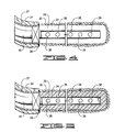
- Figure 4 is a side cross-sectional view of a horizontal open-hole wellbore penetrating an unconsolidated subterranean producing zone having a slotted liner and a production packer connected to a work or production string disposed therein.
- Figure 5 is a side cross sectional view of the horizontal open hole wellbore of Figure 4 after a hardenable resin composition coated particulate material has been placed in the annulus between the slotted liner and the wellbore and caused to harden therein and hardened resin composition particulate material has been drilled out of the slotted liner.
- the present invention provides improved methods of completing and optionally simultaneously fracture stimulating an unconsolidated subterranean zone penetrated by a wellbore.
- the methods can be performed in either vertical or horizontal wellbores which are open-hole or have casing cemented therein.
- vertical wellbore is used herein to mean the portion of a wellbore in an unconsolidated subterranean producing zone to be completed which is substantially vertical or deviated from vertical in an amount up to about 15°.
- horizontal wellbore is used herein to mean the portion of a wellbore in an unconsolidated subterranean producing zone to be completed which is substantially horizontal or at an angle from vertical in the range of from about 60° to about 120°.
- a vertical wellbore 10 having casing 14 cemented therein is illustrated extending into an unconsolidated subterranean zone 12.
- the casing 14 is bonded within the wellbore 10 by a cement sheath 16.
- a plurality of spaced perforations 18 produced in the wellbore 10 utilizing conventional perforating gun apparatus extend through the casing 14 and cement sheath 16 into the unconsolidated producing zone 12.
- a slotted liner 20 is placed in the wellbore 10 which has a length such that it substantially spans the length of the producing interval in the wellbore 10.
- the slotted liner 20 is of a diameter such that when it is disposed within the wellbore 10 an annulus 22 is formed between it and the casing 14.
- the slots 24 in the slotted liner 20 can be circular as illustrated in the drawings, or they can be rectangular or other shape. Generally, when circular slots are utilized they are at least 3/8" in diameter, and when rectangular slots are utilized they are at least 1/4" wide by 1" long.
- the slotted liner 20 is connected to a production packer 26 which is in turn connected to a work string or production string 28.
- a hardenable resin composition coated particulate material 27 which will be described further hereinbelow is injected into the perforations 18 and into the annulus 22 by way of the work or production string 28 and the slotted liner 20. That is, a carrier liquid slurry of the hardenable resin composition coated particulate material 27 is pumped from the surface through the work or production string 28 and packer 26 into the slotted liner 20.
- the slurry flows through the slots 24 and through the open end of the slotted liner 20, into the annulus 22 and into the perforations 18.
- the carrier liquid in the slurry leaks off through the perforations 18 into the unconsolidated zone 12 causing the hardenable resin composition coated particulate material 27 to be uniformly packed in the perforations 18, in the annulus 22 between the slotted liner 20 and the casing 14 and within the interior of the slotted liner 14.
- the hardenable resin composition is caused to harden by allowing it to be heated in the wellbore 10 by heat from the subterranean zone 12 or by contacting it with a hardening agent as will be described further hereinbelow.
- the hardenable resin composition hardens, it consolidates the particulate material 27 into a hard permeable uniform mass which filters out and prevents the migration of formation fines and sand with fluids produced into the wellbore from the unconsolidated subterranean zone 12.
- the consolidated particulate material 27 can be drilled out of the slotted liner 20 if a pump is to be installed in the slotted liner or for other reasons.
- a horizontal open-hole wellbore 30 is illustrated.
- the wellbore 30 extends into an unconsolidated subterranean zone 32 from a cased and cemented wellbore 34 which extends to the surface.
- a slotted liner 34 is placed in the wellbore 30.
- the slotted liner 34 is connected to a production packer 36 set within the casing 37 cemented in the wellbore 34.
- a work or production string 40 is connected to the packer 36.
- the slotted liner 34 is placed in the wellbore 30 as shown in FIGURE 4.
- the annulus 39 between the slotted liner 34 and the wellbore 30 is isolated by setting the packer 36.
- a slurry of hardenable resin composition coated particulate material is injected into the wellbore 30 and subterranean zone 32 by way of the slotted liner 34 and the slots 38 therein.
- the resin coated particulate material 40 is uniformly packed into the annulus 36 between the wellbore 30 and slotted liner 34 as shown in Figure 5.
- the hardenable resin composition is then caused to harden whereby the particulate material 40 is consolidated into a uniform hard permeable mass which filters out and prevents the migration of formation fines and sand with fluids produced into the wellbore 30 from the subterranean zone 32.
- the consolidated particulate material can be drilled out of the interior of the slotted liner if desired.
- a screen in the wellbore generally is unnecessary to prevent the movement of proppant or formation materials into the wellbore; however, a screen may be positioned within the slotted liner, if desired.
- the uncoated particulate or the resin coated particulate slurry is introduced as described hereinbefore to fill the annulus and the space between the screen and the slotted liner as well as between the slotted liner and the casing or the open hole wellbore.
- the particulate forms a uniform hard permeable mass around the screen and slotted liner which filters proppant and formation materials from fluids produced through the wellbore.
- the installed screen is perforated or slotted by introduction of a perforating gun or hydrojetting tool of conventional design to create openings in the pre-existing screen such that it may then function like the slotted liner described hereinbefore.
- a slurry of resin coated particulate then is introduced down the wellbore through an appropriate tool string to enter the now slotted or perforated screen, flow through the slots and fill uniformly any open annulus and the interior of the pre-existing screen.
- the resin coated particulate then is permitted or caused to harden into a uniform hard permeable mass that filters out and prevents the migration of particulate formation materials or proppant with fluids produced into the wellbore from the subterranean formation.
- the consolidated particulate material can be drilled out of the interior of the slotted or perforated screen if desired.
- the particulate material utilized in accordance with the present invention is preferably graded sand which is sized based on a knowledge of the size of the formation fines and sand in the unconsolidated zone to prevent the formation fines and sand from passing through the consolidated permeable sand mass formed.
- the sand generally has a particle size in the range of from about 10 to about 70 mesh, U.S. Sieve Series. Preferred sand particle size distribution ranges are 1 or more of 10-20 mesh, 20-40 mesh, 40-60 mesh or 50-70 mesh, depending on the particle size and distribution of the formation fines and sand to be screened out by the particulate material.
- the graded sand can be pre-coated and mixed with a carrier liquid to form a slurry on site or the graded sand can be both coated and slurried on site.
- the hardenable resin compositions which are useful for coating sand and consolidating it into a hard permeable mass are generally comprised of a hardenable organic resin and a resin-to-sand coupling agent. Such resin compositions are well known to those skilled in the art as is their use for consolidating sand into hard permeable masses. A number of such compositions are described in detail in U.S. Patent No. 4,042,032 issued to Anderson, et al. on August 16, 1977, U.S. Patent No.
- hardenable organic resins which are particularly suitable for use in accordance with this invention are novolac resins, polyepoxide resins, polyester resins, phenol-aldehyde resins, urea-aldehyde resins, furan resins and urethane resins. These resins are available at various viscosities depending upon the molecular weights of the resins. The preferred viscosity of the organic resin used is generally in the range of from about 1 to about 1000 centipoises at 80° F. However, as will be understood, resins of higher viscosities can be utilized when mixed or blended with one or more diluents. Diluents which are generally useful with all of the various resins mentioned above include phenols, formaldehydes, furfuryl alcohol and furfural.
- the resin-to-sand coupling agent is utilized in the hardenable resin compositions to promote coupling or adhesion to sand or other similar particulate materials.
- Particularly suitable coupling agents are aminosilane compounds or mixtures of such compounds.
- a preferred such coupling agent is N-Beta-(aminoethyl)-gamma-aminopropyltrimethoxysilane.
- the hardenable resin composition used is caused to harden by allowing it to be heated in the formation or by contacting it with a hardening agent.
- a hardening agent When a hardening agent is utilized, it can be included in the resin composition (internal hardening agent) or the resin composition can be contacted with the hardening agent after the resin composition coated particulate material has been placed in the subterranean formation being completed (external hardening agent).
- An internal hardening agent is selected for use that causes the resin composition to harden after a period of time sufficient for the resin composition coated particulate material to be placed in the subterranean zone to be completed. Retarders or accelerators to lengthen or shorten the cure times can also be utilized.
- the hardenable resin composition coated particulate material is first placed in a zone followed by an over-flush solution containing the external hardening agent.
- suitable internal hardening agents include hexachloroacetone, 1,1,3-trichlorotrifluoroacetone, benzotrichloride, benzylchloride and benzalchloride.
- external hardening agents which can be used include benzotrichloride, acetic acid, formic acid and inorganic acids such as hydrochloric acid.
- the hardenable resin compositions can also include surfactants, dispersants and other additives which are well known to those skilled in the art.
- the resin coated particulate material used in accordance with this invention can be prepared in accordance with conventional batch mixing techniques followed by the suspension of the resin coated particulate material in a viscous carrier liquid.
- the carrier liquid containing hardenable resin composition coated particulate material can be prepared in a substantially continuous manner such as in accordance with the methods disclosed in U.S. Patent No. 4,829,100 issued to Murphey, et al. on May 9, 1989 or U.S. Patent No. 5,128,390 issued to Murphey, et al, on July 7, 1992.
- the carrier liquid utilized which can also be used to fracture the unconsolidated subterranean zone if desired, can be any of the various viscous carrier liquids or fracturing fluids utilized heretofore including gelled water, oil base liquids, foams or emulsions.
- the foams utilized have generally been comprised of water based liquids containing one or more foaming agents foamed with a gas such as nitrogen.
- the emulsions have been formed with two or more immiscible liquids.
- a particularly useful emulsion is comprised of a water based liquid and a liquified normally gaseous fluid such as carbon dioxide. Upon pressure release, the liquified gaseous fluid vaporizes and rapidly flows out of the formation.
- the most common carrier liquid/fracturing fluid utilized heretofore which is also preferred for use in accordance with this invention is comprised of an aqueous liquid such as fresh water or salt water combined with a gelling agent for increasing the viscosity of the liquid.
- aqueous liquid such as fresh water or salt water
- gelling agent for increasing the viscosity of the liquid.
- the increased viscosity reduces fluid loss and allows the carrier liquid to transport significant concentrations of hardenable resin composition coated particulate material into the subterranean zone to be completed.
- gelling agents include hydratable polymers which contain one or more functional groups such as hydroxyl, cis-hydroxyl, carboxyl, sulfate, sulfonate, amino or amide.
- Particularly useful such polymers are polysaccharides and derivatives thereof which contain one or more of the monosaccharides units galactose, mannose, glucoside, glucose, xylose, arabinose, fructose, glucuronic acid or pyranosyl sulfate.
- Various natural hydratable polymers contain the foregoing functional groups and units including guar gum and derivatives thereof, cellulose and derivatives thereof, and the like. Hydratable synthetic polymers and co-polymers which contain the above mentioned functional groups can also be utilized including polyacrylate, polymethylacrylate, polyacrylamide, and the like.
- Particularly preferred hydratable polymers which yield high viscosities upon hydration at relatively low concentrations are guar gum and guar derivatives such as hydroxypropylguar and carboxymethylguar and cellulose derivatives such as hydroxyethylcellulose, carboxymethylcellulose and the like.
- the viscosities of aqueous polymer solutions of the types described above can be increased by combining cross-linking agents with the polymer solutions.
- cross-linking agents which can be utilized are multivalent metal salts or compounds which are capable of releasing such metal ions in an aqueous solution.
- the above described gelled or gelled and cross-linked carrier liquids/fracturing fluids can also include gel breakers such as those of the enzyme type, the oxidizing type or the acid buffer type which are well known to those skilled in the art.
- the gel breakers cause the viscous carrier liquids/fracturing fluids to revert to thin fluids that can be produced back to the surface after they have been utilized.
- the hydraulic fracturing process generally involves pumping a viscous liquid containing suspended particulate material into the formation or zone at a rate and pressure whereby fractures are created therein.
- the continued pumping of the fracturing fluid extends the fractures in the zone and carries the particulate material into the fractures.
- the particulate material is deposited in the fractures and the fractures are prevented from closing by the presence of the particulate material therein.
- the subterranean zone to be completed can be fractured prior to or during the injection of the resin composition coated particulate material into the zone, i.e., the pumping of the carrier liquid containing the resin coated particulate material through the slotted liner into the zone.
- the resin coated particulate material can be pumped into the fractures as well as into the annulus between the slotted liner and the wellbore.
- the consolidated particulate material in the fractures functions to prop the fractures open as well as to screen out loose or incompetent formation fines and sand.
- the test apparatus was comprised of a 5' long by 2" diameter plastic tubing for simulating a wellbore. Ten equally spaced 5/8" diameter holes were drilled in the tubing along the length thereof to simulate perforations in a wellbore. A screen was placed inside the tubing over the 5/8" holes in order to retain sand introduced into the tubing therein. No back pressure was held on the tubing so as to simulate an unconsolidated high permeability formation.
- a section of 5/8" ID plastic tubing was perforated with multiple holes of 3/8" to 1/2" diameters to simulate a slotted liner.
- the 5/8" tubing was placed inside the 2" tubing without centralization. Flow tests were performed with the apparatus in both the vertical and horizontal positions.
Abstract
Description
- The present invention relates to a method of completing a well in an unconsolidated subterranean zone.
- Oil and gas wells are often completed in unconsolidated formations containing loose and incompetent fines and sand which migrate with fluids produced by the wells. The presence of formation fines and sand in the produced fluids is disadvantageous and undesirable in that the particles abrade pumping and other producing equipment and reduce the fluid production capabilities of the producing zones in the wells.
- Heretofore, unconsolidated subterranean zones have been stimulated by creating fractures in the zones and depositing particulate proppant material in the fractures to maintain them in open positions. In addition, the proppant has heretofore been consolidated within the fractures into hard permeable masses to reduce the potential of proppant flowback and migration of formation fines and sands through the fractures with produced fluids. Further, costly gravel packs which include sand screens and the like have commonly been installed in the wellbores penetrating unconsolidated zones. The gravel packs serve as filters and help to assure that fines and sand do not migrate with produced fluids into the wellbores.
- In a typical gravel pack completion, a screen is placed in the wellbore and positioned within the unconsolidated subterranean zone which is to be completed. The screen is typically connected to a tool which includes a production packer and a cross-over, and the tool is in turn connected to a work or production string. A particulate material which is usually graded sand, often referred to in the art as gravel, is pumped in a slurry down the work or production string and through the cross over whereby it flows into the annulus between the screen and the wellbore. The liquid forming the slurry leaks off into the subterranean zone and/or through the screen which is sized to prevent the sand in the slurry from flowing there- through. As a result, the sand is deposited in the annulus around the screen whereby it forms a gravel pack. The size of the sand in the gravel pack is selected such that it prevents formation fines and sand from flowing into the wellbore with produced fluids.
- A problem which is often encountered in forming gravel packs, particularly gravel packs in long and/or deviated unconsolidated producing intervals, is the formation of sand bridges in the annulus. That is, non-uniform sand packing of the annulus between the screen and the wellbore often occurs as a result of the loss of carrier liquid from the sand slurry into high permeability portions of the subterranean zone which in turn causes the formation of sand bridges in the annulus before all the sand has been placed. The sand bridges block further flow of the slurry through the annulus which leaves voids below the bridges formed. When the well is placed on production, the flow of produced fluids is concentrated through the voids in the gravel pack which soon causes the screen to be eroded and the migration of fines and sand with the produced fluids to result.
- In attempts to prevent the formation of sand bridges in gravel pack completions, special screens having internal by-pass tubes have been developed and used. While such screens have achieved varying degrees of success in avoiding sand bridges, they, along with the gravel packing procedure, are very costly.
- Thus, there are needs for improved methods of completing wells in unconsolidated subterranean zones whereby the migration of formation fines and sand with produced fluids can be economically and permanently prevented while allowing the efficient production of hydrocarbons from the unconsolidated producing zone.
- The present invention provides improved methods of completing welis, and optionally simultaneously fracture stimulating the wells, in unconsolidated subterranean zones which go towards or meet the needs described above and reduce or overcome the deficiencies of the prior art. The improved methods basically comprise the steps of placing a slotted liner in an unconsolidated subterranean zone, isolating the annulus between the slottedliner and the wellbore in the zone, injecting a hardenable resin composition coated particulate material into the zone by way of the slotted liner whereby the particulate material is uniformly packed into the annulus and into the slotted liner, and then causing the hardenable resin composition to harden whereby the particulate material is consolidated into a uniform hard permeable mass. The hard permeable mass formed in the annulus prevents the migration of formation fines and sand with fluids produced into the wellbore from the unconsolidated zone.
- As mentioned, the unconsolidated formation can be fractured prior to or during the injection of the hardenable resin composition coated particulate material into the unconsolidated producing zone, and the resin composition coated particulate material can be deposited in the fractures as well as in the annulus between the slotted liner and the wellbore. The hard permeable mass of particulate material remaining in the slotted liner can be left in the liner or drilled out of the liner as desired.
- The improved methods of this invention avoid the formation of sand bridges in the annulus between the slotted liner and the wellbore thereby producing a very effective sand screen for preventing the flowback of proppant that has been placed in the fracture, and the migration of fines and sand with produced fluids. Also, the methods are very economical to perform.
- The invention provides a method of completing an unconsolidated subterranean zone penetrated by a wellbore, which method comprises the steps of:
- (a) placing a slotted liner in said zone;
- (b) isolating the annulus between said slotted liner and said wellbore in said zone;
- (c) injecting a hardenable resin composition coated particulate material into said zone by way of said slotted liner whereby said particulate material is uniformly packed into said annulus and into said slotted liner; and then
- (d) consolidating the particulate material into a hard permeable uniform mass by hardening of the resin, said mass filtering out and preventing the migration of formation fines and sand with fluids produced into said wellbore from said zone.
-
- In order that the invention may be more fully understood, reference will be made to the accompanying drawings illustrating preferred embodiments of the invention, wherein:
- Figure 1 is a side cross-sectional view of one arrangement of a wellbore penetrating an unconsolidated subterranean producing zone having casing cemented therein, and having a slotted liner and production packer connected to a work or production string disposed therein.
- Figure 2 is a side cross-sectional view of the wellbore of Figure 1 after a hardenable resin composition coated particulate material has been placed therein and caused to harden.
- Figure 3 is a side cross-sectional view of the wellbore of Figure 1 after the hardened resin composition coated particulate material has been drilled out of the slotted liner.
- Figure 4 is a side cross-sectional view of a horizontal open-hole wellbore penetrating an unconsolidated subterranean producing zone having a slotted liner and a production packer connected to a work or production string disposed therein.
- Figure 5 is a side cross sectional view of the horizontal open hole wellbore of Figure 4 after a hardenable resin composition coated particulate material has been placed in the annulus between the slotted liner and the wellbore and caused to harden therein and hardened resin composition particulate material has been drilled out of the slotted liner.
- The present invention provides improved methods of completing and optionally simultaneously fracture stimulating an unconsolidated subterranean zone penetrated by a wellbore. The methods can be performed in either vertical or horizontal wellbores which are open-hole or have casing cemented therein. The term "vertical wellbore" is used herein to mean the portion of a wellbore in an unconsolidated subterranean producing zone to be completed which is substantially vertical or deviated from vertical in an amount up to about 15°.
- The term "horizontal wellbore" is used herein to mean the portion of a wellbore in an unconsolidated subterranean producing zone to be completed which is substantially horizontal or at an angle from vertical in the range of from about 60° to about 120°.
- Referring now to the drawings and particularly to FIGURES 1-3, a
vertical wellbore 10 havingcasing 14 cemented therein is illustrated extending into an unconsolidatedsubterranean zone 12. Thecasing 14 is bonded within thewellbore 10 by acement sheath 16. A plurality of spacedperforations 18 produced in thewellbore 10 utilizing conventional perforating gun apparatus extend through thecasing 14 andcement sheath 16 into the unconsolidated producingzone 12. - In accordance with the methods of the present invention a
slotted liner 20 is placed in thewellbore 10 which has a length such that it substantially spans the length of the producing interval in thewellbore 10. The slottedliner 20 is of a diameter such that when it is disposed within thewellbore 10 anannulus 22 is formed between it and thecasing 14. Theslots 24 in theslotted liner 20 can be circular as illustrated in the drawings, or they can be rectangular or other shape. Generally, when circular slots are utilized they are at least 3/8" in diameter, and when rectangular slots are utilized they are at least 1/4" wide by 1" long. As shown in FIGURES 1-3, theslotted liner 20 is connected to aproduction packer 26 which is in turn connected to a work string orproduction string 28. - After the
slotted liner 20 is placed in thewellbore 10, theannulus 22 between it and thecasing 14 is isolated by setting thepacker 26 in thecasing 14 as shown in FIGURE 1. Thereafter, as shown in FIGURE 2, a hardenable resin composition coated particulate material 27 which will be described further hereinbelow is injected into theperforations 18 and into theannulus 22 by way of the work orproduction string 28 and theslotted liner 20. That is, a carrier liquid slurry of the hardenable resin composition coated particulate material 27 is pumped from the surface through the work orproduction string 28 and packer 26 into the slottedliner 20. From theslotted liner 20, the slurry flows through theslots 24 and through the open end of theslotted liner 20, into theannulus 22 and into theperforations 18. The carrier liquid in the slurry leaks off through theperforations 18 into theunconsolidated zone 12 causing the hardenable resin composition coated particulate material 27 to be uniformly packed in theperforations 18, in theannulus 22 between theslotted liner 20 and thecasing 14 and within the interior of theslotted liner 14. - After the resin composition coated particulate material 27 has been packed into the
wellbore 10 as described above, the hardenable resin composition is caused to harden by allowing it to be heated in thewellbore 10 by heat from thesubterranean zone 12 or by contacting it with a hardening agent as will be described further hereinbelow. When the hardenable resin composition hardens, it consolidates the particulate material 27 into a hard permeable uniform mass which filters out and prevents the migration of formation fines and sand with fluids produced into the wellbore from the unconsolidatedsubterranean zone 12. As shown in FIGURE 3, the consolidated particulate material 27 can be drilled out of the slottedliner 20 if a pump is to be installed in the slotted liner or for other reasons. - Referring now to Figures 4 and 5, a horizontal open-
hole wellbore 30 is illustrated. Thewellbore 30 extends into an unconsolidated subterranean zone 32 from a cased and cementedwellbore 34 which extends to the surface. As described above in connection with thewellbore 10, aslotted liner 34 is placed in thewellbore 30. Theslotted liner 34 is connected to aproduction packer 36 set within thecasing 37 cemented in thewellbore 34. A work orproduction string 40 is connected to thepacker 36. - In carrying out the methods of the present invention for completing the unconsolidated subterranean zone 32 penetrated by the
wellbore 30, theslotted liner 34 is placed in thewellbore 30 as shown in FIGURE 4. Theannulus 39 between theslotted liner 34 and thewellbore 30 is isolated by setting thepacker 36. Thereafter, a slurry of hardenable resin composition coated particulate material is injected into thewellbore 30 and subterranean zone 32 by way of the slottedliner 34 and theslots 38 therein. Because the resin coated particulate material slurry is free to flow through theslots 38 as well as the open end of the slottedliner 34, the resin coatedparticulate material 40 is uniformly packed into theannulus 36 between the wellbore 30 and slottedliner 34 as shown in Figure 5. The hardenable resin composition is then caused to harden whereby theparticulate material 40 is consolidated into a uniform hard permeable mass which filters out and prevents the migration of formation fines and sand with fluids produced into the wellbore 30 from the subterranean zone 32. As shown in Figure 5, the consolidated particulate material can be drilled out of the interior of the slotted liner if desired. - It is to be understood that in view of the present invention the presence of a screen in the wellbore generally is unnecessary to prevent the movement of proppant or formation materials into the wellbore; however, a screen may be positioned within the slotted liner, if desired. In this instance the uncoated particulate or the resin coated particulate slurry is introduced as described hereinbefore to fill the annulus and the space between the screen and the slotted liner as well as between the slotted liner and the casing or the open hole wellbore. Upon consolidation of the resin coated particulate, the particulate forms a uniform hard permeable mass around the screen and slotted liner which filters proppant and formation materials from fluids produced through the wellbore.
- It also is possible to perform a remedial treatment upon a wellbore containing a previously installed screen that has been damaged or has failed to prevent undesired particulates from entering the wellbore with produced fluids. In this instance, the installed screen is perforated or slotted by introduction of a perforating gun or hydrojetting tool of conventional design to create openings in the pre-existing screen such that it may then function like the slotted liner described hereinbefore. A slurry of resin coated particulate then is introduced down the wellbore through an appropriate tool string to enter the now slotted or perforated screen, flow through the slots and fill uniformly any open annulus and the interior of the pre-existing screen. The resin coated particulate then is permitted or caused to harden into a uniform hard permeable mass that filters out and prevents the migration of particulate formation materials or proppant with fluids produced into the wellbore from the subterranean formation. The consolidated particulate material can be drilled out of the interior of the slotted or perforated screen if desired.
- The particulate material utilized in accordance with the present invention is preferably graded sand which is sized based on a knowledge of the size of the formation fines and sand in the unconsolidated zone to prevent the formation fines and sand from passing through the consolidated permeable sand mass formed. The sand generally has a particle size in the range of from about 10 to about 70 mesh, U.S. Sieve Series. Preferred sand particle size distribution ranges are 1 or more of 10-20 mesh, 20-40 mesh, 40-60 mesh or 50-70 mesh, depending on the particle size and distribution of the formation fines and sand to be screened out by the particulate material.
- The graded sand can be pre-coated and mixed with a carrier liquid to form a slurry on site or the graded sand can be both coated and slurried on site. The hardenable resin compositions which are useful for coating sand and consolidating it into a hard permeable mass are generally comprised of a hardenable organic resin and a resin-to-sand coupling agent. Such resin compositions are well known to those skilled in the art as is their use for consolidating sand into hard permeable masses. A number of such compositions are described in detail in U.S. Patent No. 4,042,032 issued to Anderson, et al. on August 16, 1977, U.S. Patent No. 4,070,865 issued to McLaughlin on January 31, 1978, U.S. Patent No. 4,829,100 issued to Murphey, et al. on May 9, 1989, U.S. Patent No. 5,058,676 issued to Fitzpatrick, et al. on October 22, 1991 and U.S. Patent No. 5,128,390 issued to Murphey, et al. on July 7, 1992, all of which are incorporated herein by reference.
- Examples of hardenable organic resins which are particularly suitable for use in accordance with this invention are novolac resins, polyepoxide resins, polyester resins, phenol-aldehyde resins, urea-aldehyde resins, furan resins and urethane resins. These resins are available at various viscosities depending upon the molecular weights of the resins. The preferred viscosity of the organic resin used is generally in the range of from about 1 to about 1000 centipoises at 80° F. However, as will be understood, resins of higher viscosities can be utilized when mixed or blended with one or more diluents. Diluents which are generally useful with all of the various resins mentioned above include phenols, formaldehydes, furfuryl alcohol and furfural.
- The resin-to-sand coupling agent is utilized in the hardenable resin compositions to promote coupling or adhesion to sand or other similar particulate materials. Particularly suitable coupling agents are aminosilane compounds or mixtures of such compounds. A preferred such coupling agent is N-Beta-(aminoethyl)-gamma-aminopropyltrimethoxysilane.
- As mentioned, the hardenable resin composition used is caused to harden by allowing it to be heated in the formation or by contacting it with a hardening agent. When a hardening agent is utilized, it can be included in the resin composition (internal hardening agent) or the resin composition can be contacted with the hardening agent after the resin composition coated particulate material has been placed in the subterranean formation being completed (external hardening agent). An internal hardening agent is selected for use that causes the resin composition to harden after a period of time sufficient for the resin composition coated particulate material to be placed in the subterranean zone to be completed. Retarders or accelerators to lengthen or shorten the cure times can also be utilized. When an external hardening agent is used, the hardenable resin composition coated particulate material is first placed in a zone followed by an over-flush solution containing the external hardening agent. Examples of suitable internal hardening agents which can be used include hexachloroacetone, 1,1,3-trichlorotrifluoroacetone, benzotrichloride, benzylchloride and benzalchloride. Examples of external hardening agents which can be used include benzotrichloride, acetic acid, formic acid and inorganic acids such as hydrochloric acid. The hardenable resin compositions can also include surfactants, dispersants and other additives which are well known to those skilled in the art.
- The resin coated particulate material used in accordance with this invention can be prepared in accordance with conventional batch mixing techniques followed by the suspension of the resin coated particulate material in a viscous carrier liquid. Alternatively, the carrier liquid containing hardenable resin composition coated particulate material can be prepared in a substantially continuous manner such as in accordance with the methods disclosed in U.S. Patent No. 4,829,100 issued to Murphey, et al. on May 9, 1989 or U.S. Patent No. 5,128,390 issued to Murphey, et al, on July 7, 1992.
- The carrier liquid utilized, which can also be used to fracture the unconsolidated subterranean zone if desired, can be any of the various viscous carrier liquids or fracturing fluids utilized heretofore including gelled water, oil base liquids, foams or emulsions. The foams utilized have generally been comprised of water based liquids containing one or more foaming agents foamed with a gas such as nitrogen. The emulsions have been formed with two or more immiscible liquids. A particularly useful emulsion is comprised of a water based liquid and a liquified normally gaseous fluid such as carbon dioxide. Upon pressure release, the liquified gaseous fluid vaporizes and rapidly flows out of the formation.
- The most common carrier liquid/fracturing fluid utilized heretofore which is also preferred for use in accordance with this invention is comprised of an aqueous liquid such as fresh water or salt water combined with a gelling agent for increasing the viscosity of the liquid. The increased viscosity reduces fluid loss and allows the carrier liquid to transport significant concentrations of hardenable resin composition coated particulate material into the subterranean zone to be completed.
- A variety of gelling agents have been utilized including hydratable polymers which contain one or more functional groups such as hydroxyl, cis-hydroxyl, carboxyl, sulfate, sulfonate, amino or amide. Particularly useful such polymers are polysaccharides and derivatives thereof which contain one or more of the monosaccharides units galactose, mannose, glucoside, glucose, xylose, arabinose, fructose, glucuronic acid or pyranosyl sulfate. Various natural hydratable polymers contain the foregoing functional groups and units including guar gum and derivatives thereof, cellulose and derivatives thereof, and the like. Hydratable synthetic polymers and co-polymers which contain the above mentioned functional groups can also be utilized including polyacrylate, polymethylacrylate, polyacrylamide, and the like.
- Particularly preferred hydratable polymers which yield high viscosities upon hydration at relatively low concentrations are guar gum and guar derivatives such as hydroxypropylguar and carboxymethylguar and cellulose derivatives such as hydroxyethylcellulose, carboxymethylcellulose and the like.
- The viscosities of aqueous polymer solutions of the types described above can be increased by combining cross-linking agents with the polymer solutions. Examples of cross-linking agents which can be utilized are multivalent metal salts or compounds which are capable of releasing such metal ions in an aqueous solution.
- The above described gelled or gelled and cross-linked carrier liquids/fracturing fluids can also include gel breakers such as those of the enzyme type, the oxidizing type or the acid buffer type which are well known to those skilled in the art. The gel breakers cause the viscous carrier liquids/fracturing fluids to revert to thin fluids that can be produced back to the surface after they have been utilized.
- The creation of one or more fractures in the unconsolidated subterranean zone to be completed in order to stimulate the production of hydrocarbons therefrom is well known to those skilled in the art. The hydraulic fracturing process generally involves pumping a viscous liquid containing suspended particulate material into the formation or zone at a rate and pressure whereby fractures are created therein. The continued pumping of the fracturing fluid extends the fractures in the zone and carries the particulate material into the fractures. Upon the reduction of the flow of the fracturing fluid and the reduction of pressure exerted on the zone, the particulate material is deposited in the fractures and the fractures are prevented from closing by the presence of the particulate material therein.
- As mentioned, the subterranean zone to be completed can be fractured prior to or during the injection of the resin composition coated particulate material into the zone, i.e., the pumping of the carrier liquid containing the resin coated particulate material through the slotted liner into the zone. Upon the creation of one or more fractures, the resin coated particulate material can be pumped into the fractures as well as into the annulus between the slotted liner and the wellbore. Upon the hardening of the resin composition, the consolidated particulate material in the fractures functions to prop the fractures open as well as to screen out loose or incompetent formation fines and sand.
- In order to further illustrate the methods of this invention, the following example is given.
- Flow tests were performed to verify the packing performance of this invention in the annulus between a simulated wellbore and a slotted liner. The test apparatus was comprised of a 5' long by 2" diameter plastic tubing for simulating a wellbore. Ten equally spaced 5/8" diameter holes were drilled in the tubing along the length thereof to simulate perforations in a wellbore. A screen was placed inside the tubing over the 5/8" holes in order to retain sand introduced into the tubing therein. No back pressure was held on the tubing so as to simulate an unconsolidated high permeability formation.
- A section of 5/8" ID plastic tubing was perforated with multiple holes of 3/8" to 1/2" diameters to simulate a slotted liner. The 5/8" tubing was placed inside the 2" tubing without centralization. Flow tests were performed with the apparatus in both the vertical and horizontal positions.
- In one flow test, an 8 pounds per gallon slurry of 20/40 mesh sand was pumped into the 5/8" tubing. The carrier liquid utilized was a viscous aqueous solution of hydrated hydroxypropylguar (at a 60 pound per 1000 gallon concentration). The sand slurry was pumped into the test apparatus with a positive displacement pump. Despite the formation of sand bridges at the high leak off areas (at the perforations), alternate paths were provided through the slotted tubing to provide a complete sand pack in the annulus.
- In another flow test, a slurry containing two pounds per gallon of 20/40 mesh sand was pumped into the 5/8" tubing. The carrier liquid utilized was a viscous aqueous solution of hydrated hydroxypropylguar (at a concentration of 30 pounds per 1000 gallon). Sand bridges were formed at each perforation, but the slurry was still able to transport sand into the annulus and a complete sand pack was produced therein.
- In another flow test, a slurry containing two pounds per gallon of 20/40 mesh sand was pumped into the test apparatus. The carrier liquid was a viscous aqueous solution of hydrated hydroxypropylguar (at a 45 pound per 1000 gallon concentration). In spite of sand bridges being formed at the perforations, a complete sand pack was produced in the annulus.
Claims (10)
- A method of completing an unconsolidated subterranean zone penetrated by a wellbore, which method comprises the steps of:(a) placing a slotted liner in said zone;(b) isolating the annulus between said slotted liner and said wellbore in said zone;(c) injecting a hardenable resin composition coated particulate material into said zone by way of said slotted liner whereby said particulate material is uniformly packed into said annulus and into said slotted liner; and then(d) consolidating the particulate material into a hard permeable uniform mass by hardening of the resin, said mass filtering out and preventing the migration of formation fines and sand with fluids produced into said wellbore from said zone.
- A method according to claim 1, which further comprises the step of drilling the hard permeable mass of particulate material formed in accordance with step (d) out of the interior of said slotted liner.
- A method according to claim 1 or 2, wherein said particulate material is sand.
- A method according to claim 1, 2 or 3, wherein said wellbore in said subterranean zone is open-hole.
- A method according to claim 1, 2 or 3, wherein said wellbore in said subterranean zone has casing cemented therein with perforations formed through the casing and cement.
- A method according to any of claims 1 to 5, which further comprises the step of creating at least one fracture in said subterranean zone prior to or while carrying out step (c).
- A method according to any of claims 1 to 6, wherein said wellbore in said zone is horizontal.
- A method according to any of claims 1 to 7, wherein said hardenable resin composition is comprised of an organic resin selected from novolak resins, polyepoxide resins, polyester resins, phenol-aldehyde resins, urea-aldehyde resins, furan resins and urethane resins.
- A method according to any of claims 1 to 8, wherein said hardenable resin is hardened in accordance with step (d) by being heated in said subterranean zone.
- A method according to any of claims 1 to 8, wherein said hardenable resin is hardened in accordance with step (d) by being contacted with a hardening agent.
Applications Claiming Priority (2)
| Application Number | Priority Date | Filing Date | Title |
|---|---|---|---|
| US951936 | 1997-10-16 | ||
| US08/951,936 US6003600A (en) | 1997-10-16 | 1997-10-16 | Methods of completing wells in unconsolidated subterranean zones |
Publications (2)
| Publication Number | Publication Date |
|---|---|
| EP0909874A2 true EP0909874A2 (en) | 1999-04-21 |
| EP0909874A3 EP0909874A3 (en) | 1999-10-27 |
Family
ID=25492356
Family Applications (1)
| Application Number | Title | Priority Date | Filing Date |
|---|---|---|---|
| EP98308373A Withdrawn EP0909874A3 (en) | 1997-10-16 | 1998-10-14 | Completing wells in unconsolidated subterranean zones |
Country Status (5)
| Country | Link |
|---|---|
| US (2) | US6003600A (en) |
| EP (1) | EP0909874A3 (en) |
| AU (1) | AU738276B2 (en) |
| CA (1) | CA2250563A1 (en) |
| NO (1) | NO984801L (en) |
Cited By (6)
| Publication number | Priority date | Publication date | Assignee | Title |
|---|---|---|---|---|
| EP1132571A1 (en) | 2000-03-07 | 2001-09-12 | Halliburton Energy Services, Inc. | Method and apparatus for frac/gravel packs |
| US6427775B1 (en) | 1997-10-16 | 2002-08-06 | Halliburton Energy Services, Inc. | Methods and apparatus for completing wells in unconsolidated subterranean zones |
| US6557635B2 (en) | 1997-10-16 | 2003-05-06 | Halliburton Energy Services, Inc. | Methods for completing wells in unconsolidated subterranean zones |
| US6776236B1 (en) | 2002-10-16 | 2004-08-17 | Halliburton Energy Services, Inc. | Methods of completing wells in unconsolidated formations |
| EP1447523A1 (en) * | 2003-02-12 | 2004-08-18 | Halliburton Energy Services, Inc. | Completing wells in unconsolidated zones |
| WO2016048302A1 (en) * | 2014-09-24 | 2016-03-31 | Halliburton Energy Services, Inc. | Silane additives for improved sand strength and conductivity in fracturing applications |
Families Citing this family (124)
| Publication number | Priority date | Publication date | Assignee | Title |
|---|---|---|---|---|
| US6155348A (en) * | 1999-05-25 | 2000-12-05 | Halliburton Energy Services, Inc. | Stimulating unconsolidated producing zones in wells |
| US6311773B1 (en) * | 2000-01-28 | 2001-11-06 | Halliburton Energy Services, Inc. | Resin composition and methods of consolidating particulate solids in wells with or without closure pressure |
| US6302207B1 (en) * | 2000-02-15 | 2001-10-16 | Halliburton Energy Services, Inc. | Methods of completing unconsolidated subterranean producing zones |
| US7100690B2 (en) * | 2000-07-13 | 2006-09-05 | Halliburton Energy Services, Inc. | Gravel packing apparatus having an integrated sensor and method for use of same |
| US6644406B1 (en) * | 2000-07-31 | 2003-11-11 | Mobil Oil Corporation | Fracturing different levels within a completion interval of a well |
| US6799637B2 (en) | 2000-10-20 | 2004-10-05 | Schlumberger Technology Corporation | Expandable tubing and method |
| US6752206B2 (en) * | 2000-08-04 | 2004-06-22 | Schlumberger Technology Corporation | Sand control method and apparatus |
| US6464007B1 (en) * | 2000-08-22 | 2002-10-15 | Exxonmobil Oil Corporation | Method and well tool for gravel packing a long well interval using low viscosity fluids |
| GB2382610B (en) * | 2000-09-20 | 2004-12-15 | Schlumberger Holdings | Method for gravel packing open holes above fracturing pressure |
| US6530574B1 (en) | 2000-10-06 | 2003-03-11 | Gary L. Bailey | Method and apparatus for expansion sealing concentric tubular structures |
| US6491104B1 (en) | 2000-10-10 | 2002-12-10 | Halliburton Energy Services, Inc. | Open-hole test method and apparatus for subterranean wells |
| NO335594B1 (en) | 2001-01-16 | 2015-01-12 | Halliburton Energy Serv Inc | Expandable devices and methods thereof |
| US6575245B2 (en) | 2001-02-08 | 2003-06-10 | Schlumberger Technology Corporation | Apparatus and methods for gravel pack completions |
| US6557634B2 (en) | 2001-03-06 | 2003-05-06 | Halliburton Energy Services, Inc. | Apparatus and method for gravel packing an interval of a wellbore |
| US6789624B2 (en) | 2002-05-31 | 2004-09-14 | Halliburton Energy Services, Inc. | Apparatus and method for gravel packing an interval of a wellbore |
| US6659179B2 (en) | 2001-05-18 | 2003-12-09 | Halliburton Energy Serv Inc | Method of controlling proppant flowback in a well |
| US6588506B2 (en) | 2001-05-25 | 2003-07-08 | Exxonmobil Corporation | Method and apparatus for gravel packing a well |
| US6516881B2 (en) | 2001-06-27 | 2003-02-11 | Halliburton Energy Services, Inc. | Apparatus and method for gravel packing an interval of a wellbore |
| US6588507B2 (en) | 2001-06-28 | 2003-07-08 | Halliburton Energy Services, Inc. | Apparatus and method for progressively gravel packing an interval of a wellbore |
| US6581689B2 (en) | 2001-06-28 | 2003-06-24 | Halliburton Energy Services, Inc. | Screen assembly and method for gravel packing an interval of a wellbore |
| US6601646B2 (en) | 2001-06-28 | 2003-08-05 | Halliburton Energy Services, Inc. | Apparatus and method for sequentially packing an interval of a wellbore |
| US6516882B2 (en) | 2001-07-16 | 2003-02-11 | Halliburton Energy Services, Inc. | Apparatus and method for gravel packing an interval of a wellbore |
| US6837308B2 (en) * | 2001-08-10 | 2005-01-04 | Bj Services Company | Apparatus and method for gravel packing |
| US6830104B2 (en) | 2001-08-14 | 2004-12-14 | Halliburton Energy Services, Inc. | Well shroud and sand control screen apparatus and completion method |
| US6857475B2 (en) * | 2001-10-09 | 2005-02-22 | Schlumberger Technology Corporation | Apparatus and methods for flow control gravel pack |
| US6601648B2 (en) | 2001-10-22 | 2003-08-05 | Charles D. Ebinger | Well completion method |
| US6702019B2 (en) | 2001-10-22 | 2004-03-09 | Halliburton Energy Services, Inc. | Apparatus and method for progressively treating an interval of a wellbore |
| US6772837B2 (en) | 2001-10-22 | 2004-08-10 | Halliburton Energy Services, Inc. | Screen assembly having diverter members and method for progressively treating an interval of a welibore |
| US6626241B2 (en) | 2001-12-06 | 2003-09-30 | Halliburton Energy Services, Inc. | Method of frac packing through existing gravel packed screens |
| US6668926B2 (en) | 2002-01-08 | 2003-12-30 | Halliburton Energy Services, Inc. | Methods of consolidating proppant in subterranean fractures |
| US6725931B2 (en) | 2002-06-26 | 2004-04-27 | Halliburton Energy Services, Inc. | Methods of consolidating proppant and controlling fines in wells |
| US6962200B2 (en) * | 2002-01-08 | 2005-11-08 | Halliburton Energy Services, Inc. | Methods and compositions for consolidating proppant in subterranean fractures |
| US6698519B2 (en) | 2002-01-18 | 2004-03-02 | Halliburton Energy Services, Inc. | Methods of forming permeable sand screens in well bores |
| US6719051B2 (en) | 2002-01-25 | 2004-04-13 | Halliburton Energy Services, Inc. | Sand control screen assembly and treatment method using the same |
| US6899176B2 (en) | 2002-01-25 | 2005-05-31 | Halliburton Energy Services, Inc. | Sand control screen assembly and treatment method using the same |
| US7096945B2 (en) * | 2002-01-25 | 2006-08-29 | Halliburton Energy Services, Inc. | Sand control screen assembly and treatment method using the same |
| US6715545B2 (en) | 2002-03-27 | 2004-04-06 | Halliburton Energy Services, Inc. | Transition member for maintaining for fluid slurry velocity therethrough and method for use of same |
| US6761218B2 (en) * | 2002-04-01 | 2004-07-13 | Halliburton Energy Services, Inc. | Methods and apparatus for improving performance of gravel packing systems |
| US6776238B2 (en) | 2002-04-09 | 2004-08-17 | Halliburton Energy Services, Inc. | Single trip method for selectively fracture packing multiple formations traversed by a wellbore |
| US6691780B2 (en) | 2002-04-18 | 2004-02-17 | Halliburton Energy Services, Inc. | Tracking of particulate flowback in subterranean wells |
| US6793017B2 (en) | 2002-07-24 | 2004-09-21 | Halliburton Energy Services, Inc. | Method and apparatus for transferring material in a wellbore |
| US7055598B2 (en) * | 2002-08-26 | 2006-06-06 | Halliburton Energy Services, Inc. | Fluid flow control device and method for use of same |
| US6705400B1 (en) | 2002-08-28 | 2004-03-16 | Halliburton Energy Services, Inc. | Methods and compositions for forming subterranean fractures containing resilient proppant packs |
| US6814139B2 (en) * | 2002-10-17 | 2004-11-09 | Halliburton Energy Services, Inc. | Gravel packing apparatus having an integrated joint connection and method for use of same |
| US20040084186A1 (en) | 2002-10-31 | 2004-05-06 | Allison David B. | Well treatment apparatus and method |
| US20040112605A1 (en) * | 2002-12-17 | 2004-06-17 | Nguyen Philip D. | Downhole systems and methods for removing particulate matter from produced fluids |
| US6857476B2 (en) | 2003-01-15 | 2005-02-22 | Halliburton Energy Services, Inc. | Sand control screen assembly having an internal seal element and treatment method using the same |
| US6886634B2 (en) * | 2003-01-15 | 2005-05-03 | Halliburton Energy Services, Inc. | Sand control screen assembly having an internal isolation member and treatment method using the same |
| US6978840B2 (en) | 2003-02-05 | 2005-12-27 | Halliburton Energy Services, Inc. | Well screen assembly and system with controllable variable flow area and method of using same for oil well fluid production |
| US20040211561A1 (en) * | 2003-03-06 | 2004-10-28 | Nguyen Philip D. | Methods and compositions for consolidating proppant in fractures |
| US7870898B2 (en) | 2003-03-31 | 2011-01-18 | Exxonmobil Upstream Research Company | Well flow control systems and methods |
| CA2519354C (en) * | 2003-03-31 | 2010-01-12 | Exxonmobil Upstream Research Company | A wellbore apparatus and method for completion, production and injection |
| US20040211559A1 (en) * | 2003-04-25 | 2004-10-28 | Nguyen Philip D. | Methods and apparatus for completing unconsolidated lateral well bores |
| US6951250B2 (en) * | 2003-05-13 | 2005-10-04 | Halliburton Energy Services, Inc. | Sealant compositions and methods of using the same to isolate a subterranean zone from a disposal well |
| US6994170B2 (en) * | 2003-05-29 | 2006-02-07 | Halliburton Energy Services, Inc. | Expandable sand control screen assembly having fluid flow control capabilities and method for use of same |
| US7140437B2 (en) * | 2003-07-21 | 2006-11-28 | Halliburton Energy Services, Inc. | Apparatus and method for monitoring a treatment process in a production interval |
| US7032667B2 (en) * | 2003-09-10 | 2006-04-25 | Halliburtonn Energy Services, Inc. | Methods for enhancing the consolidation strength of resin coated particulates |
| US20050121192A1 (en) * | 2003-12-08 | 2005-06-09 | Hailey Travis T.Jr. | Apparatus and method for gravel packing an interval of a wellbore |
| US20050173116A1 (en) | 2004-02-10 | 2005-08-11 | Nguyen Philip D. | Resin compositions and methods of using resin compositions to control proppant flow-back |
| US7211547B2 (en) | 2004-03-03 | 2007-05-01 | Halliburton Energy Services, Inc. | Resin compositions and methods of using such resin compositions in subterranean applications |
| US7299875B2 (en) | 2004-06-08 | 2007-11-27 | Halliburton Energy Services, Inc. | Methods for controlling particulate migration |
| US20060037752A1 (en) * | 2004-08-20 | 2006-02-23 | Penno Andrew D | Rat hole bypass for gravel packing assembly |
| US7191833B2 (en) * | 2004-08-24 | 2007-03-20 | Halliburton Energy Services, Inc. | Sand control screen assembly having fluid loss control capability and method for use of same |
| US7757768B2 (en) | 2004-10-08 | 2010-07-20 | Halliburton Energy Services, Inc. | Method and composition for enhancing coverage and displacement of treatment fluids into subterranean formations |
| US7883740B2 (en) | 2004-12-12 | 2011-02-08 | Halliburton Energy Services, Inc. | Low-quality particulates and methods of making and using improved low-quality particulates |
| US8703659B2 (en) * | 2005-01-24 | 2014-04-22 | Halliburton Energy Services, Inc. | Sealant composition comprising a gel system and a reduced amount of cement for a permeable zone downhole |
| US7318473B2 (en) * | 2005-03-07 | 2008-01-15 | Halliburton Energy Services, Inc. | Methods relating to maintaining the structural integrity of deviated well bores |
| US7673686B2 (en) | 2005-03-29 | 2010-03-09 | Halliburton Energy Services, Inc. | Method of stabilizing unconsolidated formation for sand control |
| US9714371B2 (en) | 2005-05-02 | 2017-07-25 | Trican Well Service Ltd. | Method for making particulate slurries and particulate slurry compositions |
| US7318474B2 (en) | 2005-07-11 | 2008-01-15 | Halliburton Energy Services, Inc. | Methods and compositions for controlling formation fines and reducing proppant flow-back |
| US8517098B2 (en) * | 2006-02-03 | 2013-08-27 | Exxonmobil Upstream Research Company | Wellbore method and apparatus for completion, production and injection |
| US8613320B2 (en) | 2006-02-10 | 2013-12-24 | Halliburton Energy Services, Inc. | Compositions and applications of resins in treating subterranean formations |
| US7926591B2 (en) | 2006-02-10 | 2011-04-19 | Halliburton Energy Services, Inc. | Aqueous-based emulsified consolidating agents suitable for use in drill-in applications |
| US7819192B2 (en) | 2006-02-10 | 2010-10-26 | Halliburton Energy Services, Inc. | Consolidating agent emulsions and associated methods |
| US7665517B2 (en) | 2006-02-15 | 2010-02-23 | Halliburton Energy Services, Inc. | Methods of cleaning sand control screens and gravel packs |
| US20080257549A1 (en) | 2006-06-08 | 2008-10-23 | Halliburton Energy Services, Inc. | Consumable Downhole Tools |
| US20070284114A1 (en) | 2006-06-08 | 2007-12-13 | Halliburton Energy Services, Inc. | Method for removing a consumable downhole tool |
| US20080000637A1 (en) * | 2006-06-29 | 2008-01-03 | Halliburton Energy Services, Inc. | Downhole flow-back control for oil and gas wells by controlling fluid entry |
| US7661476B2 (en) * | 2006-11-15 | 2010-02-16 | Exxonmobil Upstream Research Company | Gravel packing methods |
| EA017734B1 (en) * | 2006-11-15 | 2013-02-28 | Эксонмобил Апстрим Рисерч Компани | Wellbore method and apparatus for completion, production and injection |
| US7934557B2 (en) | 2007-02-15 | 2011-05-03 | Halliburton Energy Services, Inc. | Methods of completing wells for controlling water and particulate production |
| US20080202764A1 (en) | 2007-02-22 | 2008-08-28 | Halliburton Energy Services, Inc. | Consumable downhole tools |
| BRPI0810971A2 (en) | 2007-04-26 | 2015-07-21 | Trican Well Service Ltd | Fluid particulate drag control method and aqueous sludge composition method |
| US9040468B2 (en) | 2007-07-25 | 2015-05-26 | Schlumberger Technology Corporation | Hydrolyzable particle compositions, treatment fluids and methods |
| US8490698B2 (en) * | 2007-07-25 | 2013-07-23 | Schlumberger Technology Corporation | High solids content methods and slurries |
| US9080440B2 (en) | 2007-07-25 | 2015-07-14 | Schlumberger Technology Corporation | Proppant pillar placement in a fracture with high solid content fluid |
| US8490699B2 (en) * | 2007-07-25 | 2013-07-23 | Schlumberger Technology Corporation | High solids content slurry methods |
| US10011763B2 (en) | 2007-07-25 | 2018-07-03 | Schlumberger Technology Corporation | Methods to deliver fluids on a well site with variable solids concentration from solid slurries |
| US7703520B2 (en) * | 2008-01-08 | 2010-04-27 | Halliburton Energy Services, Inc. | Sand control screen assembly and associated methods |
| US7712529B2 (en) * | 2008-01-08 | 2010-05-11 | Halliburton Energy Services, Inc. | Sand control screen assembly and method for use of same |
| US7814973B2 (en) * | 2008-08-29 | 2010-10-19 | Halliburton Energy Services, Inc. | Sand control screen assembly and method for use of same |
| US7866383B2 (en) * | 2008-08-29 | 2011-01-11 | Halliburton Energy Services, Inc. | Sand control screen assembly and method for use of same |
| US7841409B2 (en) * | 2008-08-29 | 2010-11-30 | Halliburton Energy Services, Inc. | Sand control screen assembly and method for use of same |
| EA023890B1 (en) | 2008-11-03 | 2016-07-29 | Эксонмобил Апстрим Рисерч Компани | Well flow control system |
| US7762329B1 (en) | 2009-01-27 | 2010-07-27 | Halliburton Energy Services, Inc. | Methods for servicing well bores with hardenable resin compositions |
| US8662172B2 (en) * | 2010-04-12 | 2014-03-04 | Schlumberger Technology Corporation | Methods to gravel pack a well using expanding materials |
| US8511381B2 (en) | 2010-06-30 | 2013-08-20 | Schlumberger Technology Corporation | High solids content slurry methods and systems |
| US9057251B2 (en) | 2010-10-28 | 2015-06-16 | Weatherford Technology Holdings, Llc | Gravel pack inner string hydraulic locating device |
| US9447661B2 (en) | 2010-10-28 | 2016-09-20 | Weatherford Technology Holdings, Llc | Gravel pack and sand disposal device |
| US8770290B2 (en) | 2010-10-28 | 2014-07-08 | Weatherford/Lamb, Inc. | Gravel pack assembly for bottom up/toe-to-heel packing |
| US9260950B2 (en) | 2010-10-28 | 2016-02-16 | Weatherford Technologies Holdings, LLC | One trip toe-to-heel gravel pack and liner cementing assembly |
| US9085960B2 (en) | 2010-10-28 | 2015-07-21 | Weatherford Technology Holdings, Llc | Gravel pack bypass assembly |
| US10082007B2 (en) | 2010-10-28 | 2018-09-25 | Weatherford Technology Holdings, Llc | Assembly for toe-to-heel gravel packing and reverse circulating excess slurry |
| US9068435B2 (en) | 2010-10-28 | 2015-06-30 | Weatherford Technology Holdings, Llc | Gravel pack inner string adjustment device |
| US8584753B2 (en) | 2010-11-03 | 2013-11-19 | Halliburton Energy Services, Inc. | Method and apparatus for creating an annular barrier in a subterranean wellbore |
| US8607870B2 (en) | 2010-11-19 | 2013-12-17 | Schlumberger Technology Corporation | Methods to create high conductivity fractures that connect hydraulic fracture networks in a well |
| US8646528B2 (en) * | 2010-12-16 | 2014-02-11 | Halliburton Energy Services, Inc. | Compositions and methods relating to establishing circulation in stand-alone-screens without using washpipes |
| MX337002B (en) | 2010-12-16 | 2016-02-09 | Exxonmobil Upstream Res Co | Communications module for alternate path gravel packing, and method for completing a wellbore. |
| US8763700B2 (en) | 2011-09-02 | 2014-07-01 | Robert Ray McDaniel | Dual function proppants |
| US9133387B2 (en) | 2011-06-06 | 2015-09-15 | Schlumberger Technology Corporation | Methods to improve stability of high solid content fluid |
| BR112014006520B1 (en) | 2011-10-12 | 2021-05-25 | Exxonmobil Upstream Research Company | fluid filtration device for a wellbore and method for completing a wellbore |
| US9010417B2 (en) | 2012-02-09 | 2015-04-21 | Baker Hughes Incorporated | Downhole screen with exterior bypass tubes and fluid interconnections at tubular joints therefore |
| US9863228B2 (en) | 2012-03-08 | 2018-01-09 | Schlumberger Technology Corporation | System and method for delivering treatment fluid |
| US9803457B2 (en) | 2012-03-08 | 2017-10-31 | Schlumberger Technology Corporation | System and method for delivering treatment fluid |
| US9528354B2 (en) | 2012-11-14 | 2016-12-27 | Schlumberger Technology Corporation | Downhole tool positioning system and method |
| US9638013B2 (en) | 2013-03-15 | 2017-05-02 | Exxonmobil Upstream Research Company | Apparatus and methods for well control |
| WO2014149395A2 (en) | 2013-03-15 | 2014-09-25 | Exxonmobil Upstream Research Company | Sand control screen having improved reliability |
| US10100247B2 (en) | 2013-05-17 | 2018-10-16 | Preferred Technology, Llc | Proppant with enhanced interparticle bonding |
| US9388335B2 (en) | 2013-07-25 | 2016-07-12 | Schlumberger Technology Corporation | Pickering emulsion treatment fluid |
| WO2015026330A1 (en) | 2013-08-20 | 2015-02-26 | Halliburton Energy Services, Inc. | Sand control assemblies including flow rate regulators |
| GB2526297A (en) * | 2014-05-20 | 2015-11-25 | Maersk Olie & Gas | Method for stimulation of the near-wellbore reservoir of a wellbore |
| US9862881B2 (en) | 2015-05-13 | 2018-01-09 | Preferred Technology, Llc | Hydrophobic coating of particulates for enhanced well productivity |
| US11208591B2 (en) | 2016-11-16 | 2021-12-28 | Preferred Technology, Llc | Hydrophobic coating of particulates for enhanced well productivity |
| US10696896B2 (en) | 2016-11-28 | 2020-06-30 | Prefferred Technology, Llc | Durable coatings and uses thereof |
Citations (5)
| Publication number | Priority date | Publication date | Assignee | Title |
|---|---|---|---|---|
| US4042032A (en) | 1973-06-07 | 1977-08-16 | Halliburton Company | Methods of consolidating incompetent subterranean formations using aqueous treating solutions |
| US4070865A (en) | 1976-03-10 | 1978-01-31 | Halliburton Company | Method of consolidating porous formations using vinyl polymer sealer with divinylbenzene crosslinker |
| US4829100A (en) | 1987-10-23 | 1989-05-09 | Halliburton Company | Continuously forming and transporting consolidatable resin coated particulate materials in aqueous gels |
| US5058676A (en) | 1989-10-30 | 1991-10-22 | Halliburton Company | Method for setting well casing using a resin coated particulate |
| US5128390A (en) | 1991-01-22 | 1992-07-07 | Halliburton Company | Methods of forming consolidatable resin coated particulate materials in aqueous gels |
Family Cites Families (23)
| Publication number | Priority date | Publication date | Assignee | Title |
|---|---|---|---|---|
| US2207334A (en) * | 1939-03-20 | 1940-07-09 | Union Oil Co | Method and apparatus for placing a filter body in a well |
| US2288557A (en) * | 1940-06-20 | 1942-06-30 | Gulf Research Development Co | Method of and composition for providing permeable cement packs in wells |
| US3670817A (en) * | 1970-11-05 | 1972-06-20 | Shell Oil Co | Method of gravel-packing a production well borehole |
| US3696867A (en) * | 1971-02-03 | 1972-10-10 | Shell Oil Co | Resin consolidated sandpack |
| US4428436A (en) * | 1983-02-18 | 1984-01-31 | Johnson Russell D | Seed trench digger with indexing structure |
| US4800960A (en) * | 1987-12-18 | 1989-01-31 | Texaco Inc. | Consolidatable gravel pack method |
| US4945991A (en) * | 1989-08-23 | 1990-08-07 | Mobile Oil Corporation | Method for gravel packing wells |
| US5082052A (en) * | 1991-01-31 | 1992-01-21 | Mobil Oil Corporation | Apparatus for gravel packing wells |
| US5113935A (en) * | 1991-05-01 | 1992-05-19 | Mobil Oil Corporation | Gravel packing of wells |
| US5161618A (en) * | 1991-08-16 | 1992-11-10 | Mobil Oil Corporation | Multiple fractures from a single workstring |
| US5161613A (en) * | 1991-08-16 | 1992-11-10 | Mobil Oil Corporation | Apparatus for treating formations using alternate flowpaths |
| US5333688A (en) * | 1993-01-07 | 1994-08-02 | Mobil Oil Corporation | Method and apparatus for gravel packing of wells |
| US5419394A (en) * | 1993-11-22 | 1995-05-30 | Mobil Oil Corporation | Tools for delivering fluid to spaced levels in a wellbore |
| US5559086A (en) * | 1993-12-13 | 1996-09-24 | Halliburton Company | Epoxy resin composition and well treatment method |
| JPH07205067A (en) * | 1994-01-25 | 1995-08-08 | Sony Corp | Transfer mechanism of article |
| US5417284A (en) * | 1994-06-06 | 1995-05-23 | Mobil Oil Corporation | Method for fracturing and propping a formation |
| US5435391A (en) * | 1994-08-05 | 1995-07-25 | Mobil Oil Corporation | Method for fracturing and propping a formation |
| US5515915A (en) * | 1995-04-10 | 1996-05-14 | Mobil Oil Corporation | Well screen having internal shunt tubes |
| US5560427A (en) * | 1995-07-24 | 1996-10-01 | Mobil Oil Corporation | Fracturing and propping a formation using a downhole slurry splitter |
| US5588487A (en) * | 1995-09-12 | 1996-12-31 | Mobil Oil Corporation | Tool for blocking axial flow in gravel-packed well annulus |
| US5669445A (en) * | 1996-05-20 | 1997-09-23 | Halliburton Energy Services, Inc. | Well gravel pack formation method |
| US5848645A (en) * | 1996-09-05 | 1998-12-15 | Mobil Oil Corporation | Method for fracturing and gravel-packing a well |
| CA2210087A1 (en) * | 1996-09-25 | 1998-03-25 | Mobil Oil Corporation | Alternate-path well screen with protective shroud |
-
1997
- 1997-10-16 US US08/951,936 patent/US6003600A/en not_active Expired - Lifetime
-
1998
- 1998-05-26 US US09/084,906 patent/US5934376A/en not_active Expired - Lifetime
- 1998-10-14 AU AU89294/98A patent/AU738276B2/en not_active Ceased
- 1998-10-14 EP EP98308373A patent/EP0909874A3/en not_active Withdrawn
- 1998-10-15 CA CA002250563A patent/CA2250563A1/en not_active Abandoned
- 1998-10-15 NO NO984801A patent/NO984801L/en not_active Application Discontinuation
Patent Citations (5)
| Publication number | Priority date | Publication date | Assignee | Title |
|---|---|---|---|---|
| US4042032A (en) | 1973-06-07 | 1977-08-16 | Halliburton Company | Methods of consolidating incompetent subterranean formations using aqueous treating solutions |
| US4070865A (en) | 1976-03-10 | 1978-01-31 | Halliburton Company | Method of consolidating porous formations using vinyl polymer sealer with divinylbenzene crosslinker |
| US4829100A (en) | 1987-10-23 | 1989-05-09 | Halliburton Company | Continuously forming and transporting consolidatable resin coated particulate materials in aqueous gels |
| US5058676A (en) | 1989-10-30 | 1991-10-22 | Halliburton Company | Method for setting well casing using a resin coated particulate |
| US5128390A (en) | 1991-01-22 | 1992-07-07 | Halliburton Company | Methods of forming consolidatable resin coated particulate materials in aqueous gels |
Cited By (12)
| Publication number | Priority date | Publication date | Assignee | Title |
|---|---|---|---|---|
| US6427775B1 (en) | 1997-10-16 | 2002-08-06 | Halliburton Energy Services, Inc. | Methods and apparatus for completing wells in unconsolidated subterranean zones |
| US6481494B1 (en) | 1997-10-16 | 2002-11-19 | Halliburton Energy Services, Inc. | Method and apparatus for frac/gravel packs |
| US6540022B2 (en) | 1997-10-16 | 2003-04-01 | Halliburton Energy Services, Inc. | Method and apparatus for frac/gravel packs |
| US6557635B2 (en) | 1997-10-16 | 2003-05-06 | Halliburton Energy Services, Inc. | Methods for completing wells in unconsolidated subterranean zones |
| US6571872B2 (en) | 1997-10-16 | 2003-06-03 | Halliburton Energy Services, Inc. | Apparatus for completing wells in unconsolidated subterranean zones |
| US6755245B2 (en) | 1997-10-16 | 2004-06-29 | Halliburton Energy Services, Inc. | Apparatus for completing wells in unconsolidated subterranean zones |
| EP1132571A1 (en) | 2000-03-07 | 2001-09-12 | Halliburton Energy Services, Inc. | Method and apparatus for frac/gravel packs |
| US6776236B1 (en) | 2002-10-16 | 2004-08-17 | Halliburton Energy Services, Inc. | Methods of completing wells in unconsolidated formations |
| EP1447523A1 (en) * | 2003-02-12 | 2004-08-18 | Halliburton Energy Services, Inc. | Completing wells in unconsolidated zones |
| US6866099B2 (en) | 2003-02-12 | 2005-03-15 | Halliburton Energy Services, Inc. | Methods of completing wells in unconsolidated subterranean zones |
| WO2016048302A1 (en) * | 2014-09-24 | 2016-03-31 | Halliburton Energy Services, Inc. | Silane additives for improved sand strength and conductivity in fracturing applications |
| US10155902B2 (en) | 2014-09-24 | 2018-12-18 | Halliburton Energy Services, Inc. | Silane additives for improved sand strength and conductivity in fracturing applications |
Also Published As
| Publication number | Publication date |
|---|---|
| US6003600A (en) | 1999-12-21 |
| US5934376A (en) | 1999-08-10 |
| NO984801L (en) | 1999-04-19 |
| AU8929498A (en) | 1999-05-06 |
| NO984801D0 (en) | 1998-10-15 |
| AU738276B2 (en) | 2001-09-13 |
| CA2250563A1 (en) | 1999-04-16 |
| EP0909874A3 (en) | 1999-10-27 |
Similar Documents
| Publication | Publication Date | Title |
|---|---|---|
| US6003600A (en) | Methods of completing wells in unconsolidated subterranean zones | |
| AU738914B2 (en) | Methods and apparatus for completing wells in unconsolidated subterranean zones | |
| US6866099B2 (en) | Methods of completing wells in unconsolidated subterranean zones | |
| US5960880A (en) | Unconsolidated formation stimulation with sand filtration | |
| EP0864726B1 (en) | Stimulating wells in unconsolidated formations | |
| US20040211559A1 (en) | Methods and apparatus for completing unconsolidated lateral well bores | |
| EP0933498B1 (en) | Method of rapidly consolidating particulate materials in wells | |
| US6016870A (en) | Compositions and methods for consolidating unconsolidated subterranean zones | |
| US5944105A (en) | Well stabilization methods | |
| US3815680A (en) | Method for fracturing and propping unconsolidated and dilatant subterranean formations | |
| US6732800B2 (en) | Method of completing a well in an unconsolidated formation | |
| US7013973B2 (en) | Method of completing poorly consolidated formations | |
| US6626241B2 (en) | Method of frac packing through existing gravel packed screens | |
| US5492178A (en) | Well treating methods and devices using particulate blends | |
| US6155348A (en) | Stimulating unconsolidated producing zones in wells | |
| EP1087099A1 (en) | Method of competing a well in an unconsolidated subterranean zone | |
| EP1160417A2 (en) | Method and apparatus for improved fracpacking or gravel packing operations |
Legal Events
| Date | Code | Title | Description |
|---|---|---|---|
| PUAI | Public reference made under article 153(3) epc to a published international application that has entered the european phase |
Free format text: ORIGINAL CODE: 0009012 |
|
| AK | Designated contracting states |
Kind code of ref document: A2 Designated state(s): DE DK FR GB IT NL |
|
| AX | Request for extension of the european patent |
Free format text: AL;LT;LV;MK;RO;SI |
|
| PUAL | Search report despatched |
Free format text: ORIGINAL CODE: 0009013 |
|
| AK | Designated contracting states |
Kind code of ref document: A3 Designated state(s): AT BE CH CY DE DK ES FI FR GB GR IE IT LI LU MC NL PT SE |
|
| AX | Request for extension of the european patent |
Free format text: AL;LT;LV;MK;RO;SI |
|
| RIC1 | Information provided on ipc code assigned before grant |
Free format text: 6E 21B 43/02 A, 6E 21B 43/04 B |
|
| 17P | Request for examination filed |
Effective date: 19991214 |
|
| AKX | Designation fees paid |
Free format text: DE DK FR GB IT NL |
|
| 17Q | First examination report despatched |
Effective date: 20030218 |
|
| STAA | Information on the status of an ep patent application or granted ep patent |
Free format text: STATUS: THE APPLICATION IS DEEMED TO BE WITHDRAWN |
|
| 18D | Application deemed to be withdrawn |
Effective date: 20040212 |