EP0909869A2 - Hardmetal overlay for earth boring bit - Google Patents
Hardmetal overlay for earth boring bit Download PDFInfo
- Publication number
- EP0909869A2 EP0909869A2 EP98306511A EP98306511A EP0909869A2 EP 0909869 A2 EP0909869 A2 EP 0909869A2 EP 98306511 A EP98306511 A EP 98306511A EP 98306511 A EP98306511 A EP 98306511A EP 0909869 A2 EP0909869 A2 EP 0909869A2
- Authority
- EP
- European Patent Office
- Prior art keywords
- hard material
- material particulate
- overlay
- flexible mould
- earth boring
- Prior art date
- Legal status (The legal status is an assumption and is not a legal conclusion. Google has not performed a legal analysis and makes no representation as to the accuracy of the status listed.)
- Granted
Links
Images
Classifications
-
- E—FIXED CONSTRUCTIONS
- E21—EARTH DRILLING; MINING
- E21B—EARTH DRILLING, e.g. DEEP DRILLING; OBTAINING OIL, GAS, WATER, SOLUBLE OR MELTABLE MATERIALS OR A SLURRY OF MINERALS FROM WELLS
- E21B10/00—Drill bits
- E21B10/46—Drill bits characterised by wear resisting parts, e.g. diamond inserts
-
- B—PERFORMING OPERATIONS; TRANSPORTING
- B22—CASTING; POWDER METALLURGY
- B22F—WORKING METALLIC POWDER; MANUFACTURE OF ARTICLES FROM METALLIC POWDER; MAKING METALLIC POWDER; APPARATUS OR DEVICES SPECIALLY ADAPTED FOR METALLIC POWDER
- B22F7/00—Manufacture of composite layers, workpieces, or articles, comprising metallic powder, by sintering the powder, with or without compacting wherein at least one part is obtained by sintering or compression
- B22F7/06—Manufacture of composite layers, workpieces, or articles, comprising metallic powder, by sintering the powder, with or without compacting wherein at least one part is obtained by sintering or compression of composite workpieces or articles from parts, e.g. to form tipped tools
-
- C—CHEMISTRY; METALLURGY
- C23—COATING METALLIC MATERIAL; COATING MATERIAL WITH METALLIC MATERIAL; CHEMICAL SURFACE TREATMENT; DIFFUSION TREATMENT OF METALLIC MATERIAL; COATING BY VACUUM EVAPORATION, BY SPUTTERING, BY ION IMPLANTATION OR BY CHEMICAL VAPOUR DEPOSITION, IN GENERAL; INHIBITING CORROSION OF METALLIC MATERIAL OR INCRUSTATION IN GENERAL
- C23C—COATING METALLIC MATERIAL; COATING MATERIAL WITH METALLIC MATERIAL; SURFACE TREATMENT OF METALLIC MATERIAL BY DIFFUSION INTO THE SURFACE, BY CHEMICAL CONVERSION OR SUBSTITUTION; COATING BY VACUUM EVAPORATION, BY SPUTTERING, BY ION IMPLANTATION OR BY CHEMICAL VAPOUR DEPOSITION, IN GENERAL
- C23C30/00—Coating with metallic material characterised only by the composition of the metallic material, i.e. not characterised by the coating process
- C23C30/005—Coating with metallic material characterised only by the composition of the metallic material, i.e. not characterised by the coating process on hard metal substrates
-
- B—PERFORMING OPERATIONS; TRANSPORTING
- B22—CASTING; POWDER METALLURGY
- B22F—WORKING METALLIC POWDER; MANUFACTURE OF ARTICLES FROM METALLIC POWDER; MAKING METALLIC POWDER; APPARATUS OR DEVICES SPECIALLY ADAPTED FOR METALLIC POWDER
- B22F5/00—Manufacture of workpieces or articles from metallic powder characterised by the special shape of the product
- B22F2005/001—Cutting tools, earth boring or grinding tool other than table ware
-
- B—PERFORMING OPERATIONS; TRANSPORTING
- B22—CASTING; POWDER METALLURGY
- B22F—WORKING METALLIC POWDER; MANUFACTURE OF ARTICLES FROM METALLIC POWDER; MAKING METALLIC POWDER; APPARATUS OR DEVICES SPECIALLY ADAPTED FOR METALLIC POWDER
- B22F2999/00—Aspects linked to processes or compositions used in powder metallurgy
Definitions
- This invention relates to erosion and abrasion resistant overlays on the steel surfaces of earth boring bits.
- Hardmetal inlays or overlays are employed in rock drilling bits as wear, erosion, and deformation resistant cutting edges and faying surfaces.
- These overlays typically comprise composite structures of hard particles in a tough metal matrix.
- the hard particles may be a metal carbide, such as either monocrystalline WC or the cast WC/W2C eutectic, or may themselves comprise a finer cemented carbide composite material.
- a combination of hard particle types is incorporated in the materials design, and particle size distribution is controlled to attain desired performance under rock drilling conditions, such as disclosed in US patents No. 3,800,891, No. 4,726,432 and No. 4,836,307.
- the matrix of these hardmetal overlays may be iron, nickel, cobalt, or copper based, but whether formed by weld deposition, brazing, thermal spraying, or infiltration, the matrix microstructure is necessarily a solidification product.
- the hard phase(s) remain substantially solid, but the matrix phase(s) grow from a melt during cooling and thus are limited by thermodynamic, kinetic, and heat transport constraints to narrow ranges of morphology, constituency and crystal structure.
- Welded hardmetal onlays are commonly used for protection of lug "shirttail" locations of both tooth and insert of roller cone bits, although coverage is necessarily selective, due to cost and the tendency to crack which increases with areal coverage.
- thermal spray carbide composite coatings for erosion and abrasion protection of large areas.
- Various thermally sprayed coatings for drill bits are disclosed in U.S. Patents Nos. 4,396,077; 5,279,374; 5,348,770; and 5,535,838. These coatings are typically too thin, too fine grained, and too poorly bonded to survive long in severe drilling service.
- consistency of thermal spray coatings is notoriously variable due to process control sensitivity and geometric limitations during application.
- thermal spray coatings are similarly limited to solidification microstructures and subject to other process related microstructural constraints.
- SSDPM processing methodology provides more precise control of macrostructural and microstructural features than that attainable with fused overlays, as well as lower defect levels.
- Such methods and resulting full coverage products are described in U.S. Patents Nos. 4,365,679; 4,368,788; 4,372,404; 4,398,952; 4,455,278; and 4,593,776.
- the relatively slow hot isostatic pressing densification method entails onerous economic implications. It also is restricted to thermodynamically stable materials systems, effectively limiting the potential novelty attainable in composition and microstructure.
- RSSDPM processing entails forging of powder preforms at suitable pressures and temperatures to achieve full density by plastic deformations in time frames typically of a few minutes or less. Such densification avoids the development of liquid phases and significant diffusional transport.
- RSSDPM processing can be achieved by filling a flexible mould with various powders and other components to about 55% to 65% of theoretical maxi mum density, then compressing the filled mould in a cold isostatic press (CIP) at high pressure to crate an 80% to 90% dense preform. This preform is then heated to about 2100 degrees F and forged to near 100% density by direct compression using an elastic pressure transmitting particles.
- CIP cold isostatic press
- the final densification may be achieved by other rapid solid state densification processes, such as the pneumatic isostatic forging process described in U.S. Patent No. 5,561,834.
- the size of the preform is significantly smaller than the interior of mould, and the finished part is significantly smaller than its corresponding preform, although each has about the same mass.
- RSSDPM processing provides more precise control of microstructural features than that attainable with either fused overlays or slow densified PM composites.
- Such fabrication methodologies for rock bits are disclosed in U.S. patents Nos. 4,554,130; 4,592,252; and 4,630,692. Shown in these patents and also in U.S. patents No. 4,562,892 and 4,597,456 are examples of drill bits with wear resistant hardmetal overlays which exploit the flexibility and control afforded by RSSDPM. None of these patents, however, teach or anticipate process derived physical and microstructural specificity's intrinsic to RSSDPM fabrication methods. Nor do they teach economic methods for fabrication or formulation strategies for optimization of full coverage RSSDPM inlays as a function of bit design and application.
- RSSDPM Although many unique hardmetal formulations are made possible by RSSDPM, most will not be useful as rock bit hardmetal inlays because they lack the necessary balance of wear resistance, strength, and toughness. In addition, straight forward substitution of RSSDPM processing has been found to produce hardmetals which behave differently in service than their solidification counterparts. Some have exhibited unique failure progressions which disadvantage them for use in drilling service.
- RSSDPM "clone" of a conventional weld applied hardmetal made from 65 wt. percent cemented carbide pellets (30/40 mesh WC-7% Co), and 35 wt% 4620 steel powder, was found to have lower crest wear resistance than expected due to selective hard phase pullout caused by shear localization cracking in the matrix.
- the presence of sharpened interfaces combined with the formation of ferrite "halos” around carbide pellets propitiates deformation instability under high strain conditions. Even though the primary characteristics normally used to evaluate hardmetal (volume fractions, pellet hardness, matrix hardness, and porosity) were superior to conventional material, the RSSDPM clone exhibited an unexpected weakness.
- RSSDPM hardmetal in drilling service has partially refuted conventional wisdom that maximization of volume fractions of hard phase increases robustness of cutting edges.
- tooth crests formulated with high carbide loading made possible with RSSDPM methods were found to be vulnerable to macro scale cracking.
- carbide loading and particle size were pushed beyond conventional limits with increasing benefit.
- RSSDPM hard metals entails consideration of both process derived and design derived specificity's.
- the physical demands placed on hard metals differ with location on a bit, and are dependent on bit design characteristics as well as application conditions.
- the hardmetal formulations best suited to resist deformation, cracking, and wear modes operative at cutting edges or tooth crests are not optimal to resist abrasion, erosion, and bending conditions operating on cutter or tooth flanks.
- hardmetal formulations optimized for bit faces, watercourses, and gage faces will be similarly specific to local erosion, abrasion, wear, and deformation conditions.
- One preferred method of making these mould inserts employs a metal injection mould process using sintered WC-Co cemented carbide particulate and steel powder bound with an aqueous polymeric fugitive binder such as methylcellulose.
- the resulting previously formed inserts are inserted into tooth recesses in the elastomeric CIP mould prior to filling with steel powder. After forging, the inserts become fully dense integral hardmetal inlays which can exhibit constituencies covering and exceeding ranges those attainable by various solidification means.
- U.S. patent No. 4,884,477 describes the use of a fugitive adhesive on rigid female mould tooling for incorporation of hard material particulate species to achieve a superficial composite hard metal in PDC drag bit heads.
- This type of infiltration process typically uses a copper based binder material which melts at a temperature less than about 1000 degrees C. The melted binder fills the spaces between the powders packed within the mould and produces a part which has substantially the same dimensions as the interior of the mould.
- copper based matrices exhibit lower yield strength and modulus of elasticity than those of the steel alloy matrices available in RSSDPM, making the infiltrated product inferior in service, particularly where significant strains are applied to the product in service.
- the maximum practical attainable volume fraction of hard material particulate is limited to about 70 volume percent due to packing density limitations. Typically the volume percent actually attained is much lower than 70%. This limits the wear and erosion resistance of the surface of the infiltrated product.
- the coating will have a very high volume percent hard material particulate for good wear, abrasion and erosion resistance, and have a steel alloy matrix for strength and toughness. Ideally, the coating would be economical to form, even over large areas of the steel surfaces.
- the present invention provides a metallic component of an earth boring bit having a surface formed with an erosion and abrasion resistant overlay which is economical to manufacture and which meets the above described need.
- the overlay is thin, tough and hard. It is wear and erosion resistant and comprises a hard material particulate containing a metal carbide and an alloy steel matrix.
- the volume fraction of the hard material particulate in the overlay is greater than about 75%, the average particle size of the hard material particulate is between about 40 mesh and about 80 mesh, and the thickness of the overlay is less than about 0.050 inches.
- the overlay is formed simultaneously with the surface in a rapid solid state densification powder metallurgy (RSSDPM) process, and is integral with the surface.
- RSSDPM rapid solid state densification powder metallurgy
- the present invention also provides a method of manufacturing a component for an earth boring bit.
- This new method of producing forged bits or bit components with RSSDPM hardmetal overlays entails fixing a single layer of hard material particulate mixture upon a flexible CIP mould surface, followed by back filling with a substrate powder mix and CIP processing, followed by forging to full density.
- a flexible mould is made from a pattern, and a mixture of hard material particulate with a particle size of between about 40 mesh and about 80 mesh is formed. Then, a layer of the hard material particulate is fixed to the surface of the flexible mould, and powder is introduced into the flexible mould. The powder and the hard material particulate is cold compressed into a preform and then preform is separated from the flexible mould. Finally, the preform is heated in an inert atmosphere and rapidly densified to full density.
- the hard particle layer fixed to the mould be limited to about one thickness of hard particles.
- the hard particle monolayer fixed on flexible mould surfaces is compressed laterally during densification, stacking particles up to several diameters deep in the finished overlay.
- the combination of flexible female mould tooling, isostatic cold compaction, and non-isostatic forge densification has produced unexpected outcomes due to the unique kinematics of the deformations.
- Fixing a particulate layer may be achieved by pre-coating all or a portion of the flexible mould surface with a pressure sensitive adhesive (PSA) and introducing a loose powder mix(es) in one or more steps, followed by decanting the loose residual.
- PSA pressure sensitive adhesive
- Such a powder coating may be used alone or in conjunction with previously formed inserts, in various sequences.
- this method yields a product that has hard metal coverage which can extend continuously or substantially continuously over potentially complex shaped surfaces, without the attendant cost and difficulties of providing close dimensional control of previously formed inserts.
- the method permits fabrication of thinner overlays than possible with close cavity moulded previously formed inserts.
- the overlays are integral to the part, as they are formed on the surface of the part as it is densified.
- the packing and densification mechanics of this method provide unexpected characteristics in the finished overlays, wherein volume fraction of hard phase exceeds that predicted on the basis of theoretical packing density of the hard phase alone. This results from the combination of differential compactions and particle realignments during CIP and forging, accommodated by hard particle plasticity during forging.
- Products uniquely obtainable by this method include rolling tooth type bit cutters with integrally formed large area hardmetal coverage having carbide fractions of up to 95 Vol. percent. Similar overlays can be incorporated in insert type roller cutters or PDC drag bit faces, including nozzles and hydraulic courses, extending up to inserted/brazed carbide inserts or cutter elements. RSSDPM hard metal overlay gage surfaces of drag bits or roller cone cutters, as well as other bit components such as lug shirttails and stabilizer pads are also included within the scope of this invention.
- This overlay meets the need for a tough and very wear, abrasion and erosion resistant coating for the steel surfaces of drill bits.
- the overlay has a very high volume percent hard material particulate for good wear, abrasion and erosion resistance, and has a steel alloy matrix for strength and toughness. This overlay is economical to form, even over large areas of the steel surfaces.
- a perspective view of a steel tooth drill bit 2 of the present invention is shown in Figure 1.
- a steel tooth drill bit 2 typically has three rolling cutters 4, 6, 8 with a plurality of cutting teeth 10.
- the rolling cutters are mounted on lugs 5, 7.
- the shirttail area 9 of the lug 7 often experiences excessive abrasive and erosive wear during drilling.
- the exposed surfaces 12 between the teeth 10 are exposed to both abrasive wear due to engaging the earth and to erosive wear from the flushing fluid 14 which impinges their surfaces. Similar wear behaviour also occurs on the surfaces of a steel bodied drag bits 16 as shown in Figure 2.
- the surfaces 18 near hydraulic courses 20 are prone to erosive wear, and surfaces 22 near the inserted/brazed carbide inserts 24 are subjected to abrasive wear from the earth formations being drilled.
- These exposed surfaces 9, 12, 18 on bits 2, 16 may be integrally formed with erosion and abrasion resistant onlays in a rapid solid state densification powder metallurgy (RSSDPM) process.
- RSSDPM rapid solid state densification powder metallurgy
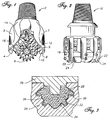
- FIG. 3 is a cross section view showing such a flexible mould 26 containing powders 28 and materials 30 for a component of an earth boring bit.
- the interior of the mould 26 shown is in the general form of one of the outer surfaces of rolling cutters 4, 6, 8 except enlarged and elongated.
- the mould 26 contains shape of teeth 32 and outer surfaces 34 of the cutter.
- a layer of hard particle particulate 36 is shown on the interior surface of the flexible mould 26.
- Powders 28 are introduced into the flexible mould 26 along with other materials 30.
- the materials 30 shown in Figure 3 are previously formed inserts as described in U.S. Patent 5,032,352. However, many other types of materials may be placed in the flexible mould 26 in addition to the previously formed inserts.
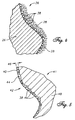
- Figure 4 is an enlarged cross section view of a portion of the hard particle layer 36 as fixed upon the flexible mould.
- the layer 36 is comprised of generally spherical particles 38 which may vary in size from about 40 mesh to about 80 mesh. Prior to densification, the layer 36 is generally a single particle in thickness (i.e. a monolayer), although due to the variations in particle size, some overlap of particles is possible.
- the particles 38 are fixed to the flexible mould 26, preferably with an adhesive (not shown). Other materials (if any) may be introduced into the mould before or after fixing the particles. Once the particles are fixed to the surface of the mould, and the other materials (if any) are introduced into the mould, back fill powders 28 are added.
- powders 28 normally contain at least some fine particles which percolate into the interstices between the hard particles 38.
- a closure 39 (shown in Figure 3) is added to the mould 26, and the entire assembly is cold densified, preferably in a CIP, to produce a preform. The preform is then heated and further densified in a rapid high pressure forging process to form a finished component.
- Shown in Figure 5 is a cross section view of a portion of the surface 40 of a steel component 41 for an earth boring drill bit with the overlay 42 of the current invention.
- the body portion 48 of the component 41 is formed from the powders 28 earlier introduced in the flexible mould 26.
- the surface 40 has an overlay 42 formed simultaneously with the surface which contains hard particles 38 and a continuous iron alloy matrix 44 between the particles 38.
- the iron alloy matrix 44 is formed from the powders 28 introduced into the flexible mould 26.
- the hard particles 38 are still generally spherical in shape, many are flattened slightly from the forces applied during densification. This deformation tends to further increase the volume density of the overlay 42.
- the particles 38 must be between about 40 mesh and about 80 mesh in diameter. This will allow stacking from one, up to about three particles deep (as shown in Figure 5) and still have an acceptable surface roughness.
- the overlay 42 on the surface 40 of the present invention greatly improves the wear, erosion, and abrasion resistance as compared to non-overlaid steel surfaces and readily survives the strains which are applied in operations.
- the thickness 46 of the overlay 42 varies, but the average thickness of the overlay rages from about one to about three times the average particle size of the hard material particulate 38.
- a rolling tooth type bit cutter 4, 6, 8 is produced with hardmetal coverage over the entire cutting structure surface.
- the cutter body 4, 6, 8 is formed from pre-alloyed steel powder and employs an integral RSSDPM composite hardmetal overlay covering the entire cutter exterior.
- the overlay 42 comprises sintered WC-Co pellets in a alloy steel matrix with thickness of about 0.010" to about 0.050".
- the fraction of sintered carbide phase in the overlay is in the rage of 75 Vol. percent to as much as 95 Vol. percent.
- the binder fraction within the hard phase is the range of 3 wt. percent to 20 wt. percent Co.
- the particle size of the hard phase is preferably between 40 mesh (.016 inches or 0.42 mm) and 80 mesh (.007 inches or 0.18 mm).
- Multi-modal size distributions may be employed to maximize final carbide density, but significant amounts of particulate 38 larger than 40 mesh will lead to wrinkling instability during densification, causing detrimental surface roughening in the finished cutter. Conversely, average particle sizes below 80 mesh exhibit reduced life in severe drilling service, especially at locations of high velocity fluid impingement.
- the preferred methods of making the above described overlay 42 on a component 41 of an earth boring bit 2, 16 include both a method for making the preform which becomes the component and a method for making the component itself.
- a pattern or other device is used to make a flexible mould 26 with interior dimensions which are scaled up representations of the finished parts.
- a mixture of hard material particulate 38 is then made by selecting powders with a particle size of between about 40 mesh and about 80 mesh.
- a layer 36 of this mixture is then fixed to a portion of the flexible mould 26.
- Powders 28 and other materials 30 are then introduced into the flexible mould 26.
- the mould 26 with its contents is then cold isostatically pressed, thereby compacting the powder and the hard material particulate into a preform.
- the complete preform is then separated from the flexible mould.
- the preform is heated in an inert atmosphere, and rapidly densified to full density.
- a pressure sensitive adhesive is applied to the interior surface of the mould 26 to fix the hard particle particulate 38.
- the component 41 may have materials 30 with differing formulations to crate thicker tooth crest and flank hardmetal inlays, while all remaining cutter shell exterior surfaces have hardmetal overlays 42 crated by the pressure sensitive adhesive method.
- insert type roller cutters or PDC drag bit faces may be covered overall, including nozzles and hydraulic courses, up to inserted/brazed carbide inserts or cutter elements.
- Receiver holes for interference fitted cutter elements may be machined after densification by some combination of electrical discharge machining (EDM), grinding, or boring.
- EDM electrical discharge machining
- the invention is not limited to any particular method of a rapid solid state densification process nor by any particular shape or configuration of the finished component.
- components such as lug shirttails, stabilizer pads, and many other components related to earth boring bits are also included within the scope of this invention.
Abstract
Description
- This invention relates to erosion and abrasion resistant overlays on the steel surfaces of earth boring bits.
- Hardmetal inlays or overlays are employed in rock drilling bits as wear, erosion, and deformation resistant cutting edges and faying surfaces.
- The strongest commonly employed hardmetals used in rock drilling bits are made by weld application of sintered tungsten carbide based tube metals or composite rods using iron alloy matrix systems. Heat input during weld deposition of such overlays is critical. Practical control limitations normally result in matrix variation due to alloying effects arising from melt incorporation of sintered carbide hard phase constituents as well as substrate material. Partial melting of cemented carbide constituents results in "blurring" of the hard phase boundaries and the incorporation of cobalt and WC particles into the matrix. Process control is typically challenged to maintain "primary" hardmetal microstructural characteristics such as constituency and volume fraction relationships of hard phases. Secondary characteristics such as matrix microstructure are derivative and cannot be readily regulated.
- These overlays typically comprise composite structures of hard particles in a tough metal matrix. The hard particles may be a metal carbide, such as either monocrystalline WC or the cast WC/W2C eutectic, or may themselves comprise a finer cemented carbide composite material. Often, a combination of hard particle types is incorporated in the materials design, and particle size distribution is controlled to attain desired performance under rock drilling conditions, such as disclosed in US patents No. 3,800,891, No. 4,726,432 and No. 4,836,307.
- The matrix of these hardmetal overlays may be iron, nickel, cobalt, or copper based, but whether formed by weld deposition, brazing, thermal spraying, or infiltration, the matrix microstructure is necessarily a solidification product. During fabrication, the hard phase(s) remain substantially solid, but the matrix phase(s) grow from a melt during cooling and thus are limited by thermodynamic, kinetic, and heat transport constraints to narrow ranges of morphology, constituency and crystal structure.
- Welded composite hard metals encounter several limitations when large areal coverage is needed such as in continuous overlays of bit cutting faces as shown in figures 1 and 2. Foremost of these is the high cost of application. Also, compatibility issues provide physical limits arising from property differentials between substrate materials and overlays, and fabrication logistics become limiting due to thermal stability issues with substrate or cutting elements. These factors have limited welded composite rod hardfacing onlays to crest and flank locations of tooth type roller cone bit cutting structures, and have precluded their use in interference fitted (insert type) roller cone bit cutting structures.
- Welded onlays have been incorporated for large areal protection of faces and gage surfaces of drag type polycrystalline diamond composite (PDC) bits. However, necessary compromises in coverage, constituency, and application method have rendered the performance/cost relationship marginal for many PDC products.
- Welded hardmetal onlays are commonly used for protection of lug "shirttail" locations of both tooth and insert of roller cone bits, although coverage is necessarily selective, due to cost and the tendency to crack which increases with areal coverage.
- Due to the aforementioned limitations, practice in both insert type roller cone and PDC drag bits has gravitated to thermal spray carbide composite coatings for erosion and abrasion protection of large areas. Various thermally sprayed coatings for drill bits are disclosed in U.S. Patents Nos. 4,396,077; 5,279,374; 5,348,770; and 5,535,838. These coatings are typically too thin, too fine grained, and too poorly bonded to survive long in severe drilling service. In addition, consistency of thermal spray coatings is notoriously variable due to process control sensitivity and geometric limitations during application. Finally, like weld applied hardmetals, thermal spray coatings are similarly limited to solidification microstructures and subject to other process related microstructural constraints.
- The development of solid state densification powder metallurgy (SSDPM) processing of composite structures has enabled the fabrication of hardmetal inlays/overlays which potentially include a range of compositions and microstructures not attainable by solidification. In addition, SSDPM processing methodology also provides more precise control of macrostructural and microstructural features than that attainable with fused overlays, as well as lower defect levels. Such methods and resulting full coverage products are described in U.S. Patents Nos. 4,365,679; 4,368,788; 4,372,404; 4,398,952; 4,455,278; and 4,593,776. However, the relatively slow hot isostatic pressing densification method entails onerous economic implications. It also is restricted to thermodynamically stable materials systems, effectively limiting the potential novelty attainable in composition and microstructure.
- The advent of rapid solid state densification powder metallurgy (RSSDPM) processing of composite structures has enabled the fabrication of hardmetal inlays/overlays which include a much broader range of possible compositions and microstructures, as well as more favourable process economics. RSSDPM processing entails forging of powder preforms at suitable pressures and temperatures to achieve full density by plastic deformations in time frames typically of a few minutes or less. Such densification avoids the development of liquid phases and significant diffusional transport. For example, RSSDPM processing can be achieved by filling a flexible mould with various powders and other components to about 55% to 65% of theoretical maxi mum density, then compressing the filled mould in a cold isostatic press (CIP) at high pressure to crate an 80% to 90% dense preform. This preform is then heated to about 2100 degrees F and forged to near 100% density by direct compression using an elastic pressure transmitting particles. Alternately, the final densification may be achieved by other rapid solid state densification processes, such as the pneumatic isostatic forging process described in U.S. Patent No. 5,561,834.
- Because the components are densified in stages, the size of the preform is significantly smaller than the interior of mould, and the finished part is significantly smaller than its corresponding preform, although each has about the same mass.
- RSSDPM processing provides more precise control of microstructural features than that attainable with either fused overlays or slow densified PM composites. Such fabrication methodologies for rock bits are disclosed in U.S. patents Nos. 4,554,130; 4,592,252; and 4,630,692. Shown in these patents and also in U.S. patents No. 4,562,892 and 4,597,456 are examples of drill bits with wear resistant hardmetal overlays which exploit the flexibility and control afforded by RSSDPM. None of these patents, however, teach or anticipate process derived physical and microstructural specificity's intrinsic to RSSDPM fabrication methods. Nor do they teach economic methods for fabrication or formulation strategies for optimization of full coverage RSSDPM inlays as a function of bit design and application.
- Although many unique hardmetal formulations are made possible by RSSDPM, most will not be useful as rock bit hardmetal inlays because they lack the necessary balance of wear resistance, strength, and toughness. In addition, straight forward substitution of RSSDPM processing has been found to produce hardmetals which behave differently in service than their solidification counterparts. Some have exhibited unique failure progressions which disadvantage them for use in drilling service.
- For example, a RSSDPM "clone" of a conventional weld applied hardmetal made from 65 wt. percent cemented carbide pellets (30/40 mesh WC-7% Co), and 35 wt% 4620 steel powder, was found to have lower crest wear resistance than expected due to selective hard phase pullout caused by shear localization cracking in the matrix. The presence of sharpened interfaces combined with the formation of ferrite "halos" around carbide pellets propitiates deformation instability under high strain conditions. Even though the primary characteristics normally used to evaluate hardmetal (volume fractions, pellet hardness, matrix hardness, and porosity) were superior to conventional material, the RSSDPM clone exhibited an unexpected weakness.
- Other experimentation with RSSDPM hardmetal in drilling service has partially refuted conventional wisdom that maximization of volume fractions of hard phase increases robustness of cutting edges. In hard formations/severe service, tooth crests formulated with high carbide loading made possible with RSSDPM methods were found to be vulnerable to macro scale cracking. However, in locations where high velocity fluid erosion dominates such as water courses and jet impinged cutter faces, carbide loading and particle size were pushed beyond conventional limits with increasing benefit.
- In U.S. Patent 5,653,299, a particular hardmetal matrix microstructure which is very advantageous for rolling cutter drill bits is shown. RSSDPM processing provides a cost effective, controllable way of achieving this matrix microstructure.
- Optimization of RSSDPM hard metals entails consideration of both process derived and design derived specificity's. The physical demands placed on hard metals differ with location on a bit, and are dependent on bit design characteristics as well as application conditions. In particular, the hardmetal formulations best suited to resist deformation, cracking, and wear modes operative at cutting edges or tooth crests are not optimal to resist abrasion, erosion, and bending conditions operating on cutter or tooth flanks. In turn, hardmetal formulations optimized for bit faces, watercourses, and gage faces will be similarly specific to local erosion, abrasion, wear, and deformation conditions.
- Forged, powder metal fabricated rock bits have been developed which incorporate composite powder pre forms in the cold isostatic press (CIP) portion of the fabrication cycle in order to produce RSSDPM hardmetal inlays. U.S. patent No. 5,032,352, herein incorporated by reference, describes in detail a R SSDPM process particularly applicable to making components for earth boring bits. In particular, the patent describes the method of incorporating previously formed inserts in a mould prior to a CIP densification cycle to form a hardmetal inlay in the finished part. The inserts are usually moulded using a powder binder mix in separate tooling.
- One preferred method of making these mould inserts employs a metal injection mould process using sintered WC-Co cemented carbide particulate and steel powder bound with an aqueous polymeric fugitive binder such as methylcellulose. The resulting previously formed inserts are inserted into tooth recesses in the elastomeric CIP mould prior to filling with steel powder. After forging, the inserts become fully dense integral hardmetal inlays which can exhibit constituencies covering and exceeding ranges those attainable by various solidification means.
- While forming a hard metal layer utilizing preformed insert structures offers performance potential not available via conventional processes, incorporation of preformed inserts requires close conformation to the flexible mould features, in order to provide dimensional control. This entails precision preform fabrication tooling and associated design effort. In addition, practical moulding limits on section thickness, aspect ratios, and particle size and volume loading of carbide prevent very thin, very large, and very dense preformed inserts such as may be desirable to achieve the most cost effective and/or functional cutter overlay configurations.
- In a completely different fabrication technology (infiltration), U.S. patent No. 4,884,477 describes the use of a fugitive adhesive on rigid female mould tooling for incorporation of hard material particulate species to achieve a superficial composite hard metal in PDC drag bit heads. This type of infiltration process typically uses a copper based binder material which melts at a temperature less than about 1000 degrees C. The melted binder fills the spaces between the powders packed within the mould and produces a part which has substantially the same dimensions as the interior of the mould. Also, copper based matrices exhibit lower yield strength and modulus of elasticity than those of the steel alloy matrices available in RSSDPM, making the infiltrated product inferior in service, particularly where significant strains are applied to the product in service. Also, in an infiltration process, the maximum practical attainable volume fraction of hard material particulate is limited to about 70 volume percent due to packing density limitations. Typically the volume percent actually attained is much lower than 70%. This limits the wear and erosion resistance of the surface of the infiltrated product.
- There is a need for a tough and very wear, abrasion and erosion resistant coating for the steel surfaces of drill bits. Preferably the coating will have a very high volume percent hard material particulate for good wear, abrasion and erosion resistance, and have a steel alloy matrix for strength and toughness. Ideally, the coating would be economical to form, even over large areas of the steel surfaces.
- The present invention provides a metallic component of an earth boring bit having a surface formed with an erosion and abrasion resistant overlay which is economical to manufacture and which meets the above described need. The overlay is thin, tough and hard. It is wear and erosion resistant and comprises a hard material particulate containing a metal carbide and an alloy steel matrix. The volume fraction of the hard material particulate in the overlay is greater than about 75%, the average particle size of the hard material particulate is between about 40 mesh and about 80 mesh, and the thickness of the overlay is less than about 0.050 inches. The overlay is formed simultaneously with the surface in a rapid solid state densification powder metallurgy (RSSDPM) process, and is integral with the surface.
- Development of the novel RSSDPM hardmetal overlay fabrication method of the present invention has resulted in heretofore unobtainable structures which provide performance benefits and process economies, as well as an optimization protocol necessary to avoid adverse surface effects while maintaining sufficient wear/erosion resistance.
- The present invention also provides a method of manufacturing a component for an earth boring bit. This new method of producing forged bits or bit components with RSSDPM hardmetal overlays entails fixing a single layer of hard material particulate mixture upon a flexible CIP mould surface, followed by back filling with a substrate powder mix and CIP processing, followed by forging to full density.
- More specifically, a flexible mould is made from a pattern, and a mixture of hard material particulate with a particle size of between about 40 mesh and about 80 mesh is formed. Then, a layer of the hard material particulate is fixed to the surface of the flexible mould, and powder is introduced into the flexible mould. The powder and the hard material particulate is cold compressed into a preform and then preform is separated from the flexible mould. Finally, the preform is heated in an inert atmosphere and rapidly densified to full density.
- It is desirable that the hard particle layer fixed to the mould be limited to about one thickness of hard particles. The hard particle monolayer fixed on flexible mould surfaces is compressed laterally during densification, stacking particles up to several diameters deep in the finished overlay. The combination of flexible female mould tooling, isostatic cold compaction, and non-isostatic forge densification has produced unexpected outcomes due to the unique kinematics of the deformations.
- Fixing a particulate layer may be achieved by pre-coating all or a portion of the flexible mould surface with a pressure sensitive adhesive (PSA) and introducing a loose powder mix(es) in one or more steps, followed by decanting the loose residual. Such a powder coating may be used alone or in conjunction with previously formed inserts, in various sequences.
- After forging, this method yields a product that has hard metal coverage which can extend continuously or substantially continuously over potentially complex shaped surfaces, without the attendant cost and difficulties of providing close dimensional control of previously formed inserts. In addition, the method permits fabrication of thinner overlays than possible with close cavity moulded previously formed inserts. The overlays are integral to the part, as they are formed on the surface of the part as it is densified.
- Moreover, the packing and densification mechanics of this method provide unexpected characteristics in the finished overlays, wherein volume fraction of hard phase exceeds that predicted on the basis of theoretical packing density of the hard phase alone. This results from the combination of differential compactions and particle realignments during CIP and forging, accommodated by hard particle plasticity during forging.
- Products uniquely obtainable by this method include rolling tooth type bit cutters with integrally formed large area hardmetal coverage having carbide fractions of up to 95 Vol. percent. Similar overlays can be incorporated in insert type roller cutters or PDC drag bit faces, including nozzles and hydraulic courses, extending up to inserted/brazed carbide inserts or cutter elements. RSSDPM hard metal overlay gage surfaces of drag bits or roller cone cutters, as well as other bit components such as lug shirttails and stabilizer pads are also included within the scope of this invention.
- This overlay meets the need for a tough and very wear, abrasion and erosion resistant coating for the steel surfaces of drill bits. The overlay has a very high volume percent hard material particulate for good wear, abrasion and erosion resistance, and has a steel alloy matrix for strength and toughness. This overlay is economical to form, even over large areas of the steel surfaces.
-
- Figure 1 is a perspective view of a steel tooth rolling cutter drill bit of the present invention,
- Figure 2 is a perspective view of a drag-type earth boring bit of the present invention,
- Figure 3 is a cross section of a flexible mould containing powders and materials for a component of an earth boring bit of the present invention,
- Figure 4 is an enlarged cross section view of a portion of the hard particle layer as fixed upon the flexible mould of the present invention, and
- Figure 5 is an enlarged cross section view of a section of the hard particle layer in a finished article of the present invention.
-
- A perspective view of a steel
tooth drill bit 2 of the present invention is shown in Figure 1. A steeltooth drill bit 2 typically has three rollingcutters teeth 10. The rolling cutters are mounted onlugs shirttail area 9 of thelug 7 often experiences excessive abrasive and erosive wear during drilling. The exposed surfaces 12 between theteeth 10 are exposed to both abrasive wear due to engaging the earth and to erosive wear from the flushingfluid 14 which impinges their surfaces. Similar wear behaviour also occurs on the surfaces of a steelbodied drag bits 16 as shown in Figure 2. Again, thesurfaces 18 nearhydraulic courses 20 are prone to erosive wear, and surfaces 22 near the inserted/brazed carbide inserts 24 are subjected to abrasive wear from the earth formations being drilled. These exposed surfaces 9, 12, 18 onbits - A
flexible mould 26 suitable for the RSSDPM process is shown in Figure 3. Figure 3 is a cross section view showing such aflexible mould 26 containingpowders 28 andmaterials 30 for a component of an earth boring bit. The interior of themould 26 shown is in the general form of one of the outer surfaces of rollingcutters mould 26 contains shape ofteeth 32 andouter surfaces 34 of the cutter. This is a typical arrangement of aflexible mould 26 used in the rapid solid state densification powder metallurgy process, just prior to the cold densification step of the RSSDPM process. A layer ofhard particle particulate 36 is shown on the interior surface of theflexible mould 26.Powders 28 are introduced into theflexible mould 26 along withother materials 30. Thematerials 30 shown in Figure 3 are previously formed inserts as described in U.S. Patent 5,032,352. However, many other types of materials may be placed in theflexible mould 26 in addition to the previously formed inserts. - Figure 4 is an enlarged cross section view of a portion of the
hard particle layer 36 as fixed upon the flexible mould. Thelayer 36 is comprised of generallyspherical particles 38 which may vary in size from about 40 mesh to about 80 mesh. Prior to densification, thelayer 36 is generally a single particle in thickness (i.e. a monolayer), although due to the variations in particle size, some overlap of particles is possible. Theparticles 38 are fixed to theflexible mould 26, preferably with an adhesive (not shown). Other materials (if any) may be introduced into the mould before or after fixing the particles. Once the particles are fixed to the surface of the mould, and the other materials (if any) are introduced into the mould, back fillpowders 28 are added. Thesepowders 28 normally contain at least some fine particles which percolate into the interstices between thehard particles 38. A closure 39 (shown in Figure 3) is added to themould 26, and the entire assembly is cold densified, preferably in a CIP, to produce a preform. The preform is then heated and further densified in a rapid high pressure forging process to form a finished component. - Shown in Figure 5 is a cross section view of a portion of the
surface 40 of asteel component 41 for an earth boring drill bit with theoverlay 42 of the current invention. Thebody portion 48 of thecomponent 41 is formed from thepowders 28 earlier introduced in theflexible mould 26. Thesurface 40 has anoverlay 42 formed simultaneously with the surface which containshard particles 38 and a continuousiron alloy matrix 44 between theparticles 38. Theiron alloy matrix 44 is formed from thepowders 28 introduced into theflexible mould 26. Although thehard particles 38 are still generally spherical in shape, many are flattened slightly from the forces applied during densification. This deformation tends to further increase the volume density of theoverlay 42. Because the hard material particulate 38 also tends to stack during densification, theparticles 38 must be between about 40 mesh and about 80 mesh in diameter. This will allow stacking from one, up to about three particles deep (as shown in Figure 5) and still have an acceptable surface roughness. Theoverlay 42 on thesurface 40 of the present invention greatly improves the wear, erosion, and abrasion resistance as compared to non-overlaid steel surfaces and readily survives the strains which are applied in operations. Thethickness 46 of theoverlay 42 varies, but the average thickness of the overlay rages from about one to about three times the average particle size of thehard material particulate 38. - In one preferred embodiment, a rolling tooth
type bit cutter cutter body overlay 42 comprises sintered WC-Co pellets in a alloy steel matrix with thickness of about 0.010" to about 0.050". The fraction of sintered carbide phase in the overlay is in the rage of 75 Vol. percent to as much as 95 Vol. percent. The binder fraction within the hard phase is the range of 3 wt. percent to 20 wt. percent Co. The particle size of the hard phase is preferably between 40 mesh (.016 inches or 0.42 mm) and 80 mesh (.007 inches or 0.18 mm). Multi-modal size distributions may be employed to maximize final carbide density, but significant amounts ofparticulate 38 larger than 40 mesh will lead to wrinkling instability during densification, causing detrimental surface roughening in the finished cutter. Conversely, average particle sizes below 80 mesh exhibit reduced life in severe drilling service, especially at locations of high velocity fluid impingement. - The preferred methods of making the above described
overlay 42 on acomponent 41 of an earthboring bit - To make the preform, a pattern or other device is used to make a
flexible mould 26 with interior dimensions which are scaled up representations of the finished parts. A mixture ofhard material particulate 38 is then made by selecting powders with a particle size of between about 40 mesh and about 80 mesh. Alayer 36 of this mixture is then fixed to a portion of theflexible mould 26.Powders 28 andother materials 30 are then introduced into theflexible mould 26. Themould 26 with its contents is then cold isostatically pressed, thereby compacting the powder and the hard material particulate into a preform. The complete preform is then separated from the flexible mould. - To make the finished component, the preform is heated in an inert atmosphere, and rapidly densified to full density.
- In the method of the preferred embodiment, a pressure sensitive adhesive is applied to the interior surface of the
mould 26 to fix thehard particle particulate 38. - In a related embodiment, the
component 41 may havematerials 30 with differing formulations to crate thicker tooth crest and flank hardmetal inlays, while all remaining cutter shell exterior surfaces havehardmetal overlays 42 crated by the pressure sensitive adhesive method. - Although the invention as described has been directed primarily to an overlay formed simultaneously with the cutters of tooth type rolling cutter bits, it is contemplated that many other types of metallic components may be similarly formed within the scope of the present invention. For instance, insert type roller cutters or PDC drag bit faces may be covered overall, including nozzles and hydraulic courses, up to inserted/brazed carbide inserts or cutter elements. Receiver holes for interference fitted cutter elements may be machined after densification by some combination of electrical discharge machining (EDM), grinding, or boring. The invention is not limited to any particular method of a rapid solid state densification process nor by any particular shape or configuration of the finished component. For instance, components such as lug shirttails, stabilizer pads, and many other components related to earth boring bits are also included within the scope of this invention.
- Whereas the present invention has been described in particular relation to the drawings attached hereto, it should be understood that other and further modifications apart from those shown or suggested herein, may be made within the scope of the present invention as defined in the appended claims.
Claims (19)
- A metallic component of an earth boring bit having a surface (40) formed with an erosion and abrasion resistant overlay (42), said overlay comprising a hard material particulate (38) containing a metal carbide and an alloy steel matrix (44), characterised in that the volume fraction of said hard material particulate (38) in said overlay (42) is greater than about 75%, the average particle size of said hard material particulate is between about 40 mesh and about 80 mesh, and the thickness of said overlay is less than about 0.050 inches.
- A metallic component of an earth boring bit according to Claim 1, wherein said metallic component is a steel component.
- A metallic component of an earth boring bit according to Claim 1 or Claim 2, wherein said metallic component is forged with rapid solid state densification powder metallurgy processing.
- A metallic component of an earth boring bit according to any of the preceding claims, wherein the thickness of said overlay (42) is greater than about 0.010 inches.
- A metallic component of an earth boring bit any of the preceding claims, wherein the volume fraction of said hard material particulate (38) in said overlay (42) is less than about 95%.
- A metallic component of an earth boring bit according to any of the preceding claims, wherein the average thickness of said overlay (42) is greater than or equal to one, and less than about three, times the average particle size of said hard material particulate (38).
- A metallic component of an earth boring bit according to any of the preceding claims, wherein said hard material particulate (38) is substantially spherical.
- A metallic component of an earth boring bit according to any of the preceding claims, wherein said hard material particulate (38) comprises sintered tungsten carbide with a cobalt binder.
- A metallic component of an earth boring bit according to Claim 8, wherein the fraction of said binder is greater than about 3 weight percent of said hard material particulate (38).
- A method of manufacturing a component of an earth boring bit with a wear and abrasion resistant overlay in a rapid solid state densification powder metallurgy process comprising the steps of:a) forming a flexible mould (26) with an interior surface and an exterior surface from a pattern,b) forming a mixture of hard material particulate (38) with a particle size of between about 40 mesh and about 80 mesh,c) fixing a layer of said hard material particulate (38) to a portion of said flexible mould (26),d) introducing powder (28) to said flexible mould,e) cold compacting said powder and said hard material particulate into a preform,f) separating said preform from said flexible mould,g) heating said preform in an inert atmosphere, andh) rapidly densifying said preform to full density.
- The method according to Claim 10, wherein said hard material particulate comprises sintered tungsten carbide pellets (38).
- The method according to Claim 10 or Claim 11, wherein said layer is substantially a monolayer of said hard material particulate (38).
- The method according to any of Claims 10 to 12, wherein said hard material particulate (38) is substantially spherical.
- A method according to any of Claims 10 to 13, including the step of applying a pressure sensitive adhesive to a portion of the interior surface of said flexible mould (26), before fixing said layer of hard material particulate (38) to a portion of said flexible mould, said layer being fixed to a portion of said pressure sensitive adhesive.
- A method of manufacturing a preform for consolidation in a rapid solid state densification powder metallurgy process comprising the steps of:a) forming a flexible mould (26) with an interior surface and an exterior surface from a pattern,b) forming a mixture of hard material particulate (38) with a particle size of between about 40 mesh and about 80 mesh,c) fixing a layer of said hard material particulate to a portion of said flexible mould,d) introducing powder (28) to said flexible mould,e) compacting said flexible mould into a preform, andf) separating said preform from said flexible mould.
- The method according to Claim 15, wherein said hard material particulate comprises sintered tungsten carbide pellets (38).
- The method according to Claim 15 or Claim 16, wherein said layer is substantially a monolayer of said hard material particulate (38).
- The method according to any of Claims 15 to 17, wherein said hard material particulate (38) is substantially spherical.
- A method according to any of Claims 15 to 18, including the step of applying a pressure sensitive adhesive to a portion of the interior surface of said flexible mould (26), before fixing said layer of hard material particulate (38) to a portion of said flexible mould, said layer being fixed to a portion of said pressure sensitive adhesive.
Applications Claiming Priority (2)
| Application Number | Priority Date | Filing Date | Title |
|---|---|---|---|
| US08/950,286 US5967248A (en) | 1997-10-14 | 1997-10-14 | Rock bit hardmetal overlay and process of manufacture |
| US950286 | 1997-10-14 |
Publications (3)
| Publication Number | Publication Date |
|---|---|
| EP0909869A2 true EP0909869A2 (en) | 1999-04-21 |
| EP0909869A3 EP0909869A3 (en) | 1999-04-28 |
| EP0909869B1 EP0909869B1 (en) | 2003-06-11 |
Family
ID=25490227
Family Applications (1)
| Application Number | Title | Priority Date | Filing Date |
|---|---|---|---|
| EP98306511A Expired - Lifetime EP0909869B1 (en) | 1997-10-14 | 1998-08-14 | Hardmetal overlay for earth boring bit |
Country Status (3)
| Country | Link |
|---|---|
| US (2) | US5967248A (en) |
| EP (1) | EP0909869B1 (en) |
| CA (1) | CA2247599C (en) |
Cited By (2)
| Publication number | Priority date | Publication date | Assignee | Title |
|---|---|---|---|---|
| GB2376242B (en) * | 2001-05-01 | 2005-11-23 | Smith International | Roller cone bits with wear and fracture resistant surface |
| US9103004B2 (en) | 2005-10-03 | 2015-08-11 | Kennametal Inc. | Hardfacing composition and article having hardfacing deposit |
Families Citing this family (64)
| Publication number | Priority date | Publication date | Assignee | Title |
|---|---|---|---|---|
| JP2000080407A (en) * | 1998-09-03 | 2000-03-21 | Ykk Corp | Manufacture of formed part |
| US6060016A (en) * | 1998-11-11 | 2000-05-09 | Camco International, Inc. | Pneumatic isostatic forging of sintered compacts |
| US6454030B1 (en) | 1999-01-25 | 2002-09-24 | Baker Hughes Incorporated | Drill bits and other articles of manufacture including a layer-manufactured shell integrally secured to a cast structure and methods of fabricating same |
| US6135218A (en) * | 1999-03-09 | 2000-10-24 | Camco International Inc. | Fixed cutter drill bits with thin, integrally formed wear and erosion resistant surfaces |
| JP3479668B2 (en) * | 1999-03-23 | 2003-12-15 | 株式会社小松製作所 | Undercarriage device for tracked vehicle and method for reinforcing hardfacing thereof |
| JP2000342986A (en) | 1999-03-30 | 2000-12-12 | Komatsu Ltd | Bit for crushing industrial waste |
| US6360832B1 (en) | 2000-01-03 | 2002-03-26 | Baker Hughes Incorporated | Hardfacing with multiple grade layers |
| US6530441B1 (en) | 2000-06-27 | 2003-03-11 | Smith International, Inc. | Cutting element geometry for roller cone drill bit |
| US6651756B1 (en) | 2000-11-17 | 2003-11-25 | Baker Hughes Incorporated | Steel body drill bits with tailored hardfacing structural elements |
| JP3915889B2 (en) * | 2001-10-26 | 2007-05-16 | Ykk株式会社 | Nickel-free white copper alloy and method for producing nickel-free white copper alloy |
| JP2003180410A (en) * | 2001-12-14 | 2003-07-02 | Ykk Corp | Method of manufacturing slide fastener and attached article with composition members |
| JP3713233B2 (en) * | 2001-12-14 | 2005-11-09 | Ykk株式会社 | Copper alloy for slide fasteners with excellent continuous castability |
| KR100437683B1 (en) * | 2001-12-18 | 2004-06-30 | 전언찬 | corner make method for micro milling cutter |
| US6766870B2 (en) | 2002-08-21 | 2004-07-27 | Baker Hughes Incorporated | Mechanically shaped hardfacing cutting/wear structures |
| US6923276B2 (en) | 2003-02-19 | 2005-08-02 | Baker Hughes Incorporated | Streamlined mill-toothed cone for earth boring bit |
| US7625521B2 (en) | 2003-06-05 | 2009-12-01 | Smith International, Inc. | Bonding of cutters in drill bits |
| US20040245024A1 (en) * | 2003-06-05 | 2004-12-09 | Kembaiyan Kumar T. | Bit body formed of multiple matrix materials and method for making the same |
| JP4363523B2 (en) * | 2004-07-01 | 2009-11-11 | 株式会社ハーモニック・ドライブ・システムズ | Manufacturing method of bearing race |
| US7398840B2 (en) * | 2005-04-14 | 2008-07-15 | Halliburton Energy Services, Inc. | Matrix drill bits and method of manufacture |
| CN100567696C (en) * | 2005-04-14 | 2009-12-09 | 霍利贝顿能源服务公司 | Matrix drill bits and manufacture method |
| US20060237236A1 (en) * | 2005-04-26 | 2006-10-26 | Harold Sreshta | Composite structure having a non-planar interface and method of making same |
| US7776256B2 (en) | 2005-11-10 | 2010-08-17 | Baker Huges Incorporated | Earth-boring rotary drill bits and methods of manufacturing earth-boring rotary drill bits having particle-matrix composite bit bodies |
| US7703555B2 (en) | 2005-09-09 | 2010-04-27 | Baker Hughes Incorporated | Drilling tools having hardfacing with nickel-based matrix materials and hard particles |
| US8002052B2 (en) | 2005-09-09 | 2011-08-23 | Baker Hughes Incorporated | Particle-matrix composite drill bits with hardfacing |
| US7997359B2 (en) | 2005-09-09 | 2011-08-16 | Baker Hughes Incorporated | Abrasive wear-resistant hardfacing materials, drill bits and drilling tools including abrasive wear-resistant hardfacing materials |
| US7597159B2 (en) | 2005-09-09 | 2009-10-06 | Baker Hughes Incorporated | Drill bits and drilling tools including abrasive wear-resistant materials |
| RU2423549C2 (en) | 2005-10-03 | 2011-07-10 | Кеннаметал Инк. | Composition for surface strengthening and item with coating for surface strengtening |
| US7913779B2 (en) * | 2005-11-10 | 2011-03-29 | Baker Hughes Incorporated | Earth-boring rotary drill bits including bit bodies having boron carbide particles in aluminum or aluminum-based alloy matrix materials, and methods for forming such bits |
| US8770324B2 (en) | 2008-06-10 | 2014-07-08 | Baker Hughes Incorporated | Earth-boring tools including sinterbonded components and partially formed tools configured to be sinterbonded |
| US7802495B2 (en) | 2005-11-10 | 2010-09-28 | Baker Hughes Incorporated | Methods of forming earth-boring rotary drill bits |
| US7784567B2 (en) | 2005-11-10 | 2010-08-31 | Baker Hughes Incorporated | Earth-boring rotary drill bits including bit bodies comprising reinforced titanium or titanium-based alloy matrix materials, and methods for forming such bits |
| US7807099B2 (en) | 2005-11-10 | 2010-10-05 | Baker Hughes Incorporated | Method for forming earth-boring tools comprising silicon carbide composite materials |
| WO2007114524A1 (en) * | 2006-03-30 | 2007-10-11 | Komatsu Ltd. | Wear-resistant particle and wear-resistant structural member |
| EP2066864A1 (en) | 2006-08-30 | 2009-06-10 | Baker Hughes Incorporated | Methods for applying wear-resistant material to exterior surfaces of earth-boring tools and resulting structures |
| US8272295B2 (en) * | 2006-12-07 | 2012-09-25 | Baker Hughes Incorporated | Displacement members and intermediate structures for use in forming at least a portion of bit bodies of earth-boring rotary drill bits |
| US7775287B2 (en) | 2006-12-12 | 2010-08-17 | Baker Hughes Incorporated | Methods of attaching a shank to a body of an earth-boring drilling tool, and tools formed by such methods |
| US7841259B2 (en) | 2006-12-27 | 2010-11-30 | Baker Hughes Incorporated | Methods of forming bit bodies |
| US8347990B2 (en) * | 2008-05-15 | 2013-01-08 | Smith International, Inc. | Matrix bit bodies with multiple matrix materials |
| US7878275B2 (en) * | 2008-05-15 | 2011-02-01 | Smith International, Inc. | Matrix bit bodies with multiple matrix materials |
| US20090321144A1 (en) * | 2008-06-30 | 2009-12-31 | Wyble Kevin J | Protecting an element from excessive surface wear by localized hardening |
| US8261632B2 (en) | 2008-07-09 | 2012-09-11 | Baker Hughes Incorporated | Methods of forming earth-boring drill bits |
| US8617289B2 (en) * | 2008-08-12 | 2013-12-31 | Smith International, Inc. | Hardfacing compositions for earth boring tools |
| US8535408B2 (en) | 2009-04-29 | 2013-09-17 | Reedhycalog, L.P. | High thermal conductivity hardfacing |
| US20100276208A1 (en) * | 2009-04-29 | 2010-11-04 | Jiinjen Albert Sue | High thermal conductivity hardfacing for drilling applications |
| US20110000718A1 (en) * | 2009-07-02 | 2011-01-06 | Smith International, Inc. | Integrated cast matrix sleeve api connection bit body and method of using and manufacturing the same |
| US8945720B2 (en) * | 2009-08-06 | 2015-02-03 | National Oilwell Varco, L.P. | Hard composite with deformable constituent and method of applying to earth-engaging tool |
| US8061408B2 (en) * | 2009-10-13 | 2011-11-22 | Varel Europe S.A.S. | Casting method for matrix drill bits and reamers |
| EP2501504B1 (en) * | 2009-11-16 | 2016-09-14 | Varel Europe S.A.S. | Compensation grooves to absorb dilatation during infiltration of a matrix drill bit |
| US8950518B2 (en) * | 2009-11-18 | 2015-02-10 | Smith International, Inc. | Matrix tool bodies with erosion resistant and/or wear resistant matrix materials |
| EP2528703A2 (en) * | 2010-01-25 | 2012-12-05 | Varel Europe S.A.S. | Self positioning of the steel blank in the graphite mold |
| US20120067651A1 (en) * | 2010-09-16 | 2012-03-22 | Smith International, Inc. | Hardfacing compositions, methods of applying the hardfacing compositions, and tools using such hardfacing compositions |
| US8997900B2 (en) | 2010-12-15 | 2015-04-07 | National Oilwell DHT, L.P. | In-situ boron doped PDC element |
| US8733475B2 (en) | 2011-01-28 | 2014-05-27 | National Oilwell DHT, L.P. | Drill bit with enhanced hydraulics and erosion-shield cutting teeth |
| US8607899B2 (en) | 2011-02-18 | 2013-12-17 | National Oilwell Varco, L.P. | Rock bit and cutter teeth geometries |
| US9364936B2 (en) | 2011-10-12 | 2016-06-14 | National Oilwell DHT, L.P. | Dispersion of hardphase particles in an infiltrant |
| US9435158B2 (en) * | 2011-10-14 | 2016-09-06 | Varel International Ind., L.P | Use of tungsten carbide tube rod to hard-face PDC matrix |
| CN104321501B (en) * | 2012-05-30 | 2017-05-17 | 哈利伯顿能源服务公司 | Manufacture of well tools with matrix materials |
| US9140071B2 (en) | 2012-11-26 | 2015-09-22 | National Oilwell DHT, L.P. | Apparatus and method for retaining inserts of a rolling cone drill bit |
| CN103726792A (en) * | 2013-12-03 | 2014-04-16 | 常州深倍超硬材料有限公司 | Abrasion-resistant tool |
| US10570669B2 (en) * | 2017-01-13 | 2020-02-25 | Baker Hughes, A Ge Company, Llc | Earth-boring tools having impregnated cutting structures and methods of forming and using the same |
| US10414949B2 (en) * | 2017-06-27 | 2019-09-17 | The Boeing Company | Coatings and coating systems containing high density metal material |
| EP3670035A1 (en) * | 2018-12-21 | 2020-06-24 | Hilti Aktiengesellschaft | Method for producing a processing segment for dry drilling of materials |
| EP3670040A1 (en) * | 2018-12-21 | 2020-06-24 | Hilti Aktiengesellschaft | Method for producing a segment for dry processing of materials |
| EP3898039A1 (en) * | 2018-12-21 | 2021-10-27 | Hilti Aktiengesellschaft | Method for producing a green body and method for further processing the green body to form a machining segment for the dry machining of concrete materials |
Citations (20)
| Publication number | Priority date | Publication date | Assignee | Title |
|---|---|---|---|---|
| US3800891A (en) | 1968-04-18 | 1974-04-02 | Hughes Tool Co | Hardfacing compositions and gage hardfacing on rolling cutter rock bits |
| US4368788A (en) | 1980-09-10 | 1983-01-18 | Reed Rock Bit Company | Metal cutting tools utilizing gradient composites |
| US4372404A (en) | 1980-09-10 | 1983-02-08 | Reed Rock Bit Company | Cutting teeth for rolling cutter drill bit |
| US4396077A (en) | 1981-09-21 | 1983-08-02 | Strata Bit Corporation | Drill bit with carbide coated cutting face |
| US4398952A (en) | 1980-09-10 | 1983-08-16 | Reed Rock Bit Company | Methods of manufacturing gradient composite metallic structures |
| US4455278A (en) | 1980-12-02 | 1984-06-19 | Skf Industrial Trading & Development Company, B.V. | Method for producing an object on which an exterior layer is applied by thermal spraying and object, in particular a drill bit, obtained pursuant to this method |
| US4554130A (en) | 1984-10-01 | 1985-11-19 | Cdp, Ltd. | Consolidation of a part from separate metallic components |
| US4562892A (en) | 1984-07-23 | 1986-01-07 | Cdp, Ltd. | Rolling cutters for drill bits |
| US4592252A (en) | 1984-07-23 | 1986-06-03 | Cdp, Ltd. | Rolling cutters for drill bits, and processes to produce same |
| US4593776A (en) | 1984-03-28 | 1986-06-10 | Smith International, Inc. | Rock bits having metallurgically bonded cutter inserts |
| US4597456A (en) | 1984-07-23 | 1986-07-01 | Cdp, Ltd. | Conical cutters for drill bits, and processes to produce same |
| US4630692A (en) | 1984-07-23 | 1986-12-23 | Cdp, Ltd. | Consolidation of a drilling element from separate metallic components |
| US4726432A (en) | 1987-07-13 | 1988-02-23 | Hughes Tool Company-Usa | Differentially hardfaced rock bit |
| US4836307A (en) | 1987-12-29 | 1989-06-06 | Smith International, Inc. | Hard facing for milled tooth rock bits |
| US4884477A (en) | 1988-03-31 | 1989-12-05 | Eastman Christensen Company | Rotary drill bit with abrasion and erosion resistant facing |
| US5032352A (en) | 1990-09-21 | 1991-07-16 | Ceracon, Inc. | Composite body formation of consolidated powder metal part |
| US5279374A (en) | 1990-08-17 | 1994-01-18 | Sievers G Kelly | Downhole drill bit cone with uninterrupted refractory coating |
| US5535838A (en) | 1993-03-19 | 1996-07-16 | Smith International, Inc. | High performance overlay for rock drilling bits |
| US5561834A (en) | 1995-05-02 | 1996-10-01 | General Motors Corporation | Pneumatic isostatic compaction of sintered compacts |
| US5653299A (en) | 1995-11-17 | 1997-08-05 | Camco International Inc. | Hardmetal facing for rolling cutter drill bit |
Family Cites Families (14)
| Publication number | Priority date | Publication date | Assignee | Title |
|---|---|---|---|---|
| US3989554A (en) * | 1973-06-18 | 1976-11-02 | Hughes Tool Company | Composite hardfacing of air hardening steel and particles of tungsten carbide |
| NL7703234A (en) * | 1977-03-25 | 1978-09-27 | Skf Ind Trading & Dev | METHOD FOR MANUFACTURING A DRILL CHUCK INCLUDING HARD WEAR-RESISTANT ELEMENTS, AND DRILL CHAPTER MADE ACCORDING TO THE METHOD |
| US4365679A (en) * | 1980-12-02 | 1982-12-28 | Skf Engineering And Research Centre, B.V. | Drill bit |
| US4499795A (en) * | 1983-09-23 | 1985-02-19 | Strata Bit Corporation | Method of drill bit manufacture |
| US4539175A (en) * | 1983-09-26 | 1985-09-03 | Metal Alloys Inc. | Method of object consolidation employing graphite particulate |
| US4856311A (en) * | 1987-06-11 | 1989-08-15 | Vital Force, Inc. | Apparatus and method for the rapid attainment of high hydrostatic pressures and concurrent delivery to a workpiece |
| GB8725671D0 (en) * | 1987-11-03 | 1987-12-09 | Reed Tool Co | Manufacture of rotary drill bits |
| US4944774A (en) * | 1987-12-29 | 1990-07-31 | Smith International, Inc. | Hard facing for milled tooth rock bits |
| US4942750A (en) * | 1989-01-23 | 1990-07-24 | Vital Force, Inc. | Apparatus and method for the rapid attainment of high hydrostatic pressures and concurrent delivery to a workpiece |
| EP0446673A1 (en) * | 1990-03-14 | 1991-09-18 | Asea Brown Boveri Ag | Process for preparing a sintered article having a compact outer layer and a smooth surface |
| US5110542A (en) * | 1991-03-04 | 1992-05-05 | Vital Force, Inc. | Rapid densification of materials |
| US5492186A (en) * | 1994-09-30 | 1996-02-20 | Baker Hughes Incorporated | Steel tooth bit with a bi-metallic gage hardfacing |
| US5663512A (en) * | 1994-11-21 | 1997-09-02 | Baker Hughes Inc. | Hardfacing composition for earth-boring bits |
| US5816090A (en) * | 1995-12-11 | 1998-10-06 | Ametek Specialty Metal Products Division | Method for pneumatic isostatic processing of a workpiece |
-
1997
- 1997-10-14 US US08/950,286 patent/US5967248A/en not_active Expired - Lifetime
-
1998
- 1998-08-14 EP EP98306511A patent/EP0909869B1/en not_active Expired - Lifetime
- 1998-09-17 CA CA002247599A patent/CA2247599C/en not_active Expired - Lifetime
-
1999
- 1999-07-26 US US09/360,751 patent/US6045750A/en not_active Expired - Lifetime
Patent Citations (21)
| Publication number | Priority date | Publication date | Assignee | Title |
|---|---|---|---|---|
| US3800891A (en) | 1968-04-18 | 1974-04-02 | Hughes Tool Co | Hardfacing compositions and gage hardfacing on rolling cutter rock bits |
| US4368788A (en) | 1980-09-10 | 1983-01-18 | Reed Rock Bit Company | Metal cutting tools utilizing gradient composites |
| US4372404A (en) | 1980-09-10 | 1983-02-08 | Reed Rock Bit Company | Cutting teeth for rolling cutter drill bit |
| US4398952A (en) | 1980-09-10 | 1983-08-16 | Reed Rock Bit Company | Methods of manufacturing gradient composite metallic structures |
| US4455278A (en) | 1980-12-02 | 1984-06-19 | Skf Industrial Trading & Development Company, B.V. | Method for producing an object on which an exterior layer is applied by thermal spraying and object, in particular a drill bit, obtained pursuant to this method |
| US4396077A (en) | 1981-09-21 | 1983-08-02 | Strata Bit Corporation | Drill bit with carbide coated cutting face |
| US4593776A (en) | 1984-03-28 | 1986-06-10 | Smith International, Inc. | Rock bits having metallurgically bonded cutter inserts |
| US4597456A (en) | 1984-07-23 | 1986-07-01 | Cdp, Ltd. | Conical cutters for drill bits, and processes to produce same |
| US4592252A (en) | 1984-07-23 | 1986-06-03 | Cdp, Ltd. | Rolling cutters for drill bits, and processes to produce same |
| US4562892A (en) | 1984-07-23 | 1986-01-07 | Cdp, Ltd. | Rolling cutters for drill bits |
| US4630692A (en) | 1984-07-23 | 1986-12-23 | Cdp, Ltd. | Consolidation of a drilling element from separate metallic components |
| US4554130A (en) | 1984-10-01 | 1985-11-19 | Cdp, Ltd. | Consolidation of a part from separate metallic components |
| US4726432A (en) | 1987-07-13 | 1988-02-23 | Hughes Tool Company-Usa | Differentially hardfaced rock bit |
| US4836307A (en) | 1987-12-29 | 1989-06-06 | Smith International, Inc. | Hard facing for milled tooth rock bits |
| US4884477A (en) | 1988-03-31 | 1989-12-05 | Eastman Christensen Company | Rotary drill bit with abrasion and erosion resistant facing |
| US5279374A (en) | 1990-08-17 | 1994-01-18 | Sievers G Kelly | Downhole drill bit cone with uninterrupted refractory coating |
| US5348770A (en) | 1990-08-17 | 1994-09-20 | Sievers G Kelly | Method of forming an uninterrupted refractory coating on a downhole drill bit cone |
| US5032352A (en) | 1990-09-21 | 1991-07-16 | Ceracon, Inc. | Composite body formation of consolidated powder metal part |
| US5535838A (en) | 1993-03-19 | 1996-07-16 | Smith International, Inc. | High performance overlay for rock drilling bits |
| US5561834A (en) | 1995-05-02 | 1996-10-01 | General Motors Corporation | Pneumatic isostatic compaction of sintered compacts |
| US5653299A (en) | 1995-11-17 | 1997-08-05 | Camco International Inc. | Hardmetal facing for rolling cutter drill bit |
Cited By (4)
| Publication number | Priority date | Publication date | Assignee | Title |
|---|---|---|---|---|
| GB2376242B (en) * | 2001-05-01 | 2005-11-23 | Smith International | Roller cone bits with wear and fracture resistant surface |
| GB2414487A (en) * | 2001-05-01 | 2005-11-30 | Smith International | A Milled tooth bit with a wear and fracture resistant surface |
| GB2414487B (en) * | 2001-05-01 | 2006-01-25 | Smith International | Roller cone bits with wear and fracture resistant surface |
| US9103004B2 (en) | 2005-10-03 | 2015-08-11 | Kennametal Inc. | Hardfacing composition and article having hardfacing deposit |
Also Published As
| Publication number | Publication date |
|---|---|
| US5967248A (en) | 1999-10-19 |
| CA2247599C (en) | 2007-05-15 |
| CA2247599A1 (en) | 1999-04-14 |
| US6045750A (en) | 2000-04-04 |
| EP0909869A3 (en) | 1999-04-28 |
| EP0909869B1 (en) | 2003-06-11 |
Similar Documents
| Publication | Publication Date | Title |
|---|---|---|
| EP0909869B1 (en) | Hardmetal overlay for earth boring bit | |
| CA2384401C (en) | Roller cone bits with wear and fracture resistant surface | |
| CA2657926C (en) | Cemented tungsten carbide rock bit cone | |
| US9347274B2 (en) | Earth-boring tools and methods of forming earth-boring tools | |
| JP6585179B2 (en) | Ultra-hard structure and its manufacturing method | |
| EP1960630B1 (en) | Methods of forming earth-boring rotary drill bits | |
| CN101356031B (en) | Earth-boring rotary drill bits and methods of manufacturing earth-boring rotary drill bits having particle-matrix composite bit bodies | |
| US8002052B2 (en) | Particle-matrix composite drill bits with hardfacing | |
| US20090301788A1 (en) | Composite metal, cemented carbide bit construction | |
| US20100104874A1 (en) | High pressure sintering with carbon additives | |
| CN101275213A (en) | Method of manufacturing a part comprising at least one block made from a dense material | |
| US20120080240A1 (en) | Diamond impregnated cutting structures, earth-boring drill bits and other tools including diamond impregnated cutting structures, and related methods | |
| WO2017009417A1 (en) | Superhard polycrystalline constructions and methods of making same | |
| WO2009140123A2 (en) | Matrix bit bodies with multiple matrix materials | |
| WO2010056476A2 (en) | Carburized monotungsten and ditungsten carbide eutectic particles, materials and earth-boring tools including such particles, and methods of forming such particles, materials, and tools | |
| EP2570245B1 (en) | Hardfacing composition having a specific particle size distribution | |
| CN109722582B (en) | Metal matrix composite materials for additive manufacturing of downhole tools | |
| WO2017011415A1 (en) | Infiltrated cutting tools and related methods | |
| US20190145180A1 (en) | Impregnated cutting structures, earth-boring tools including the impregnated cutting structures, and related methods | |
| CA2265399C (en) | Metal-matrix diamond or cubic boron nitride composites | |
| JPH0133542B2 (en) |
Legal Events
| Date | Code | Title | Description |
|---|---|---|---|
| PUAI | Public reference made under article 153(3) epc to a published international application that has entered the european phase |
Free format text: ORIGINAL CODE: 0009012 |
|
| PUAL | Search report despatched |
Free format text: ORIGINAL CODE: 0009013 |
|
| AK | Designated contracting states |
Kind code of ref document: A2 Designated state(s): FR GB IT NL |
|
| AX | Request for extension of the european patent |
Free format text: AL;LT;LV;MK;RO;SI |
|
| AK | Designated contracting states |
Kind code of ref document: A3 Designated state(s): AT BE CH CY DE DK ES FI FR GB GR IE IT LI LU MC NL PT SE |
|
| AX | Request for extension of the european patent |
Free format text: AL;LT;LV;MK;RO;SI |
|
| 17P | Request for examination filed |
Effective date: 19991020 |
|
| AKX | Designation fees paid |
Free format text: FR GB IT NL |
|
| REG | Reference to a national code |
Ref country code: DE Ref legal event code: 8566 |
|
| GRAH | Despatch of communication of intention to grant a patent |
Free format text: ORIGINAL CODE: EPIDOS IGRA |
|
| GRAH | Despatch of communication of intention to grant a patent |
Free format text: ORIGINAL CODE: EPIDOS IGRA |
|
| GRAA | (expected) grant |
Free format text: ORIGINAL CODE: 0009210 |
|
| AK | Designated contracting states |
Designated state(s): FR GB IT NL |
|
| REG | Reference to a national code |
Ref country code: GB Ref legal event code: FG4D |
|
| RAP2 | Party data changed (patent owner data changed or rights of a patent transferred) |
Owner name: CAMCO INTERNATIONAL (UK) LTD. |
|
| NLT2 | Nl: modifications (of names), taken from the european patent patent bulletin |
Owner name: CAMCO INTERNATIONAL (UK) LTD. |
|
| ET | Fr: translation filed | ||
| PLBE | No opposition filed within time limit |
Free format text: ORIGINAL CODE: 0009261 |
|
| STAA | Information on the status of an ep patent application or granted ep patent |
Free format text: STATUS: NO OPPOSITION FILED WITHIN TIME LIMIT |
|
| 26N | No opposition filed |
Effective date: 20040312 |
|
| REG | Reference to a national code |
Ref country code: FR Ref legal event code: PLFP Year of fee payment: 19 |
|
| REG | Reference to a national code |
Ref country code: FR Ref legal event code: PLFP Year of fee payment: 20 |
|
| PGFP | Annual fee paid to national office [announced via postgrant information from national office to epo] |
Ref country code: NL Payment date: 20170814 Year of fee payment: 20 |
|
| PGFP | Annual fee paid to national office [announced via postgrant information from national office to epo] |
Ref country code: IT Payment date: 20170824 Year of fee payment: 20 Ref country code: GB Payment date: 20170809 Year of fee payment: 20 Ref country code: FR Payment date: 20170714 Year of fee payment: 20 |
|
| REG | Reference to a national code |
Ref country code: NL Ref legal event code: MK Effective date: 20180813 |
|
| REG | Reference to a national code |
Ref country code: GB Ref legal event code: PE20 Expiry date: 20180813 |
|
| PG25 | Lapsed in a contracting state [announced via postgrant information from national office to epo] |
Ref country code: GB Free format text: LAPSE BECAUSE OF EXPIRATION OF PROTECTION Effective date: 20180813 |