EP0908757A2 - Liquid crystal display - Google Patents
Liquid crystal display Download PDFInfo
- Publication number
- EP0908757A2 EP0908757A2 EP98204145A EP98204145A EP0908757A2 EP 0908757 A2 EP0908757 A2 EP 0908757A2 EP 98204145 A EP98204145 A EP 98204145A EP 98204145 A EP98204145 A EP 98204145A EP 0908757 A2 EP0908757 A2 EP 0908757A2
- Authority
- EP
- European Patent Office
- Prior art keywords
- light
- liquid crystal
- plate
- crystal panel
- prism
- Prior art date
- Legal status (The legal status is an assumption and is not a legal conclusion. Google has not performed a legal analysis and makes no representation as to the accuracy of the status listed.)
- Granted
Links
Images


Classifications
-
- G—PHYSICS
- G02—OPTICS
- G02B—OPTICAL ELEMENTS, SYSTEMS OR APPARATUS
- G02B6/00—Light guides; Structural details of arrangements comprising light guides and other optical elements, e.g. couplings
- G02B6/0001—Light guides; Structural details of arrangements comprising light guides and other optical elements, e.g. couplings specially adapted for lighting devices or systems
- G02B6/0011—Light guides; Structural details of arrangements comprising light guides and other optical elements, e.g. couplings specially adapted for lighting devices or systems the light guides being planar or of plate-like form
- G02B6/0033—Means for improving the coupling-out of light from the light guide
- G02B6/005—Means for improving the coupling-out of light from the light guide provided by one optical element, or plurality thereof, placed on the light output side of the light guide
- G02B6/0053—Prismatic sheet or layer; Brightness enhancement element, sheet or layer
-
- F—MECHANICAL ENGINEERING; LIGHTING; HEATING; WEAPONS; BLASTING
- F21—LIGHTING
- F21V—FUNCTIONAL FEATURES OR DETAILS OF LIGHTING DEVICES OR SYSTEMS THEREOF; STRUCTURAL COMBINATIONS OF LIGHTING DEVICES WITH OTHER ARTICLES, NOT OTHERWISE PROVIDED FOR
- F21V5/00—Refractors for light sources
- F21V5/02—Refractors for light sources of prismatic shape
-
- G—PHYSICS
- G02—OPTICS
- G02B—OPTICAL ELEMENTS, SYSTEMS OR APPARATUS
- G02B6/00—Light guides; Structural details of arrangements comprising light guides and other optical elements, e.g. couplings
- G02B6/0001—Light guides; Structural details of arrangements comprising light guides and other optical elements, e.g. couplings specially adapted for lighting devices or systems
- G02B6/0011—Light guides; Structural details of arrangements comprising light guides and other optical elements, e.g. couplings specially adapted for lighting devices or systems the light guides being planar or of plate-like form
- G02B6/0081—Mechanical or electrical aspects of the light guide and light source in the lighting device peculiar to the adaptation to planar light guides, e.g. concerning packaging
- G02B6/0086—Positioning aspects
- G02B6/0088—Positioning aspects of the light guide or other optical sheets in the package
-
- G—PHYSICS
- G02—OPTICS
- G02B—OPTICAL ELEMENTS, SYSTEMS OR APPARATUS
- G02B6/00—Light guides; Structural details of arrangements comprising light guides and other optical elements, e.g. couplings
- G02B6/0001—Light guides; Structural details of arrangements comprising light guides and other optical elements, e.g. couplings specially adapted for lighting devices or systems
- G02B6/0011—Light guides; Structural details of arrangements comprising light guides and other optical elements, e.g. couplings specially adapted for lighting devices or systems the light guides being planar or of plate-like form
- G02B6/0081—Mechanical or electrical aspects of the light guide and light source in the lighting device peculiar to the adaptation to planar light guides, e.g. concerning packaging
- G02B6/0086—Positioning aspects
- G02B6/009—Positioning aspects of the light source in the package
-
- G—PHYSICS
- G02—OPTICS
- G02F—OPTICAL DEVICES OR ARRANGEMENTS FOR THE CONTROL OF LIGHT BY MODIFICATION OF THE OPTICAL PROPERTIES OF THE MEDIA OF THE ELEMENTS INVOLVED THEREIN; NON-LINEAR OPTICS; FREQUENCY-CHANGING OF LIGHT; OPTICAL LOGIC ELEMENTS; OPTICAL ANALOGUE/DIGITAL CONVERTERS
- G02F1/00—Devices or arrangements for the control of the intensity, colour, phase, polarisation or direction of light arriving from an independent light source, e.g. switching, gating or modulating; Non-linear optics
- G02F1/01—Devices or arrangements for the control of the intensity, colour, phase, polarisation or direction of light arriving from an independent light source, e.g. switching, gating or modulating; Non-linear optics for the control of the intensity, phase, polarisation or colour
- G02F1/13—Devices or arrangements for the control of the intensity, colour, phase, polarisation or direction of light arriving from an independent light source, e.g. switching, gating or modulating; Non-linear optics for the control of the intensity, phase, polarisation or colour based on liquid crystals, e.g. single liquid crystal display cells
- G02F1/133—Constructional arrangements; Operation of liquid crystal cells; Circuit arrangements
- G02F1/1333—Constructional arrangements; Manufacturing methods
- G02F1/1335—Structural association of cells with optical devices, e.g. polarisers or reflectors
- G02F1/1336—Illuminating devices
- G02F1/133615—Edge-illuminating devices, i.e. illuminating from the side
-
- G—PHYSICS
- G02—OPTICS
- G02F—OPTICAL DEVICES OR ARRANGEMENTS FOR THE CONTROL OF LIGHT BY MODIFICATION OF THE OPTICAL PROPERTIES OF THE MEDIA OF THE ELEMENTS INVOLVED THEREIN; NON-LINEAR OPTICS; FREQUENCY-CHANGING OF LIGHT; OPTICAL LOGIC ELEMENTS; OPTICAL ANALOGUE/DIGITAL CONVERTERS
- G02F1/00—Devices or arrangements for the control of the intensity, colour, phase, polarisation or direction of light arriving from an independent light source, e.g. switching, gating or modulating; Non-linear optics
- G02F1/01—Devices or arrangements for the control of the intensity, colour, phase, polarisation or direction of light arriving from an independent light source, e.g. switching, gating or modulating; Non-linear optics for the control of the intensity, phase, polarisation or colour
- G02F1/13—Devices or arrangements for the control of the intensity, colour, phase, polarisation or direction of light arriving from an independent light source, e.g. switching, gating or modulating; Non-linear optics for the control of the intensity, phase, polarisation or colour based on liquid crystals, e.g. single liquid crystal display cells
- G02F1/133—Constructional arrangements; Operation of liquid crystal cells; Circuit arrangements
- G02F1/1333—Constructional arrangements; Manufacturing methods
- G02F1/1345—Conductors connecting electrodes to cell terminals
- G02F1/13452—Conductors connecting driver circuitry and terminals of panels
-
- G—PHYSICS
- G02—OPTICS
- G02B—OPTICAL ELEMENTS, SYSTEMS OR APPARATUS
- G02B6/00—Light guides; Structural details of arrangements comprising light guides and other optical elements, e.g. couplings
- G02B6/0001—Light guides; Structural details of arrangements comprising light guides and other optical elements, e.g. couplings specially adapted for lighting devices or systems
- G02B6/0011—Light guides; Structural details of arrangements comprising light guides and other optical elements, e.g. couplings specially adapted for lighting devices or systems the light guides being planar or of plate-like form
- G02B6/0033—Means for improving the coupling-out of light from the light guide
- G02B6/0035—Means for improving the coupling-out of light from the light guide provided on the surface of the light guide or in the bulk of it
- G02B6/0045—Means for improving the coupling-out of light from the light guide provided on the surface of the light guide or in the bulk of it by shaping at least a portion of the light guide
- G02B6/0046—Tapered light guide, e.g. wedge-shaped light guide
-
- G—PHYSICS
- G02—OPTICS
- G02B—OPTICAL ELEMENTS, SYSTEMS OR APPARATUS
- G02B6/00—Light guides; Structural details of arrangements comprising light guides and other optical elements, e.g. couplings
- G02B6/0001—Light guides; Structural details of arrangements comprising light guides and other optical elements, e.g. couplings specially adapted for lighting devices or systems
- G02B6/0011—Light guides; Structural details of arrangements comprising light guides and other optical elements, e.g. couplings specially adapted for lighting devices or systems the light guides being planar or of plate-like form
- G02B6/0033—Means for improving the coupling-out of light from the light guide
- G02B6/005—Means for improving the coupling-out of light from the light guide provided by one optical element, or plurality thereof, placed on the light output side of the light guide
- G02B6/0051—Diffusing sheet or layer
-
- G—PHYSICS
- G02—OPTICS
- G02B—OPTICAL ELEMENTS, SYSTEMS OR APPARATUS
- G02B6/00—Light guides; Structural details of arrangements comprising light guides and other optical elements, e.g. couplings
- G02B6/0001—Light guides; Structural details of arrangements comprising light guides and other optical elements, e.g. couplings specially adapted for lighting devices or systems
- G02B6/0011—Light guides; Structural details of arrangements comprising light guides and other optical elements, e.g. couplings specially adapted for lighting devices or systems the light guides being planar or of plate-like form
- G02B6/0033—Means for improving the coupling-out of light from the light guide
- G02B6/005—Means for improving the coupling-out of light from the light guide provided by one optical element, or plurality thereof, placed on the light output side of the light guide
- G02B6/0055—Reflecting element, sheet or layer
-
- G—PHYSICS
- G02—OPTICS
- G02B—OPTICAL ELEMENTS, SYSTEMS OR APPARATUS
- G02B6/00—Light guides; Structural details of arrangements comprising light guides and other optical elements, e.g. couplings
- G02B6/0001—Light guides; Structural details of arrangements comprising light guides and other optical elements, e.g. couplings specially adapted for lighting devices or systems
- G02B6/0011—Light guides; Structural details of arrangements comprising light guides and other optical elements, e.g. couplings specially adapted for lighting devices or systems the light guides being planar or of plate-like form
- G02B6/0066—Light guides; Structural details of arrangements comprising light guides and other optical elements, e.g. couplings specially adapted for lighting devices or systems the light guides being planar or of plate-like form characterised by the light source being coupled to the light guide
- G02B6/007—Incandescent lamp or gas discharge lamp
- G02B6/0071—Incandescent lamp or gas discharge lamp with elongated shape, e.g. tube
-
- G—PHYSICS
- G02—OPTICS
- G02F—OPTICAL DEVICES OR ARRANGEMENTS FOR THE CONTROL OF LIGHT BY MODIFICATION OF THE OPTICAL PROPERTIES OF THE MEDIA OF THE ELEMENTS INVOLVED THEREIN; NON-LINEAR OPTICS; FREQUENCY-CHANGING OF LIGHT; OPTICAL LOGIC ELEMENTS; OPTICAL ANALOGUE/DIGITAL CONVERTERS
- G02F1/00—Devices or arrangements for the control of the intensity, colour, phase, polarisation or direction of light arriving from an independent light source, e.g. switching, gating or modulating; Non-linear optics
- G02F1/01—Devices or arrangements for the control of the intensity, colour, phase, polarisation or direction of light arriving from an independent light source, e.g. switching, gating or modulating; Non-linear optics for the control of the intensity, phase, polarisation or colour
- G02F1/13—Devices or arrangements for the control of the intensity, colour, phase, polarisation or direction of light arriving from an independent light source, e.g. switching, gating or modulating; Non-linear optics for the control of the intensity, phase, polarisation or colour based on liquid crystals, e.g. single liquid crystal display cells
- G02F1/133—Constructional arrangements; Operation of liquid crystal cells; Circuit arrangements
- G02F1/1333—Constructional arrangements; Manufacturing methods
- G02F1/133374—Constructional arrangements; Manufacturing methods for displaying permanent signs or marks
-
- G—PHYSICS
- G02—OPTICS
- G02F—OPTICAL DEVICES OR ARRANGEMENTS FOR THE CONTROL OF LIGHT BY MODIFICATION OF THE OPTICAL PROPERTIES OF THE MEDIA OF THE ELEMENTS INVOLVED THEREIN; NON-LINEAR OPTICS; FREQUENCY-CHANGING OF LIGHT; OPTICAL LOGIC ELEMENTS; OPTICAL ANALOGUE/DIGITAL CONVERTERS
- G02F1/00—Devices or arrangements for the control of the intensity, colour, phase, polarisation or direction of light arriving from an independent light source, e.g. switching, gating or modulating; Non-linear optics
- G02F1/01—Devices or arrangements for the control of the intensity, colour, phase, polarisation or direction of light arriving from an independent light source, e.g. switching, gating or modulating; Non-linear optics for the control of the intensity, phase, polarisation or colour
- G02F1/13—Devices or arrangements for the control of the intensity, colour, phase, polarisation or direction of light arriving from an independent light source, e.g. switching, gating or modulating; Non-linear optics for the control of the intensity, phase, polarisation or colour based on liquid crystals, e.g. single liquid crystal display cells
- G02F1/133—Constructional arrangements; Operation of liquid crystal cells; Circuit arrangements
- G02F1/1333—Constructional arrangements; Manufacturing methods
- G02F1/1335—Structural association of cells with optical devices, e.g. polarisers or reflectors
- G02F1/133502—Antiglare, refractive index matching layers
-
- G—PHYSICS
- G02—OPTICS
- G02F—OPTICAL DEVICES OR ARRANGEMENTS FOR THE CONTROL OF LIGHT BY MODIFICATION OF THE OPTICAL PROPERTIES OF THE MEDIA OF THE ELEMENTS INVOLVED THEREIN; NON-LINEAR OPTICS; FREQUENCY-CHANGING OF LIGHT; OPTICAL LOGIC ELEMENTS; OPTICAL ANALOGUE/DIGITAL CONVERTERS
- G02F1/00—Devices or arrangements for the control of the intensity, colour, phase, polarisation or direction of light arriving from an independent light source, e.g. switching, gating or modulating; Non-linear optics
- G02F1/01—Devices or arrangements for the control of the intensity, colour, phase, polarisation or direction of light arriving from an independent light source, e.g. switching, gating or modulating; Non-linear optics for the control of the intensity, phase, polarisation or colour
- G02F1/13—Devices or arrangements for the control of the intensity, colour, phase, polarisation or direction of light arriving from an independent light source, e.g. switching, gating or modulating; Non-linear optics for the control of the intensity, phase, polarisation or colour based on liquid crystals, e.g. single liquid crystal display cells
- G02F1/133—Constructional arrangements; Operation of liquid crystal cells; Circuit arrangements
- G02F1/1333—Constructional arrangements; Manufacturing methods
- G02F1/1335—Structural association of cells with optical devices, e.g. polarisers or reflectors
- G02F1/133553—Reflecting elements
-
- Y—GENERAL TAGGING OF NEW TECHNOLOGICAL DEVELOPMENTS; GENERAL TAGGING OF CROSS-SECTIONAL TECHNOLOGIES SPANNING OVER SEVERAL SECTIONS OF THE IPC; TECHNICAL SUBJECTS COVERED BY FORMER USPC CROSS-REFERENCE ART COLLECTIONS [XRACs] AND DIGESTS
- Y10—TECHNICAL SUBJECTS COVERED BY FORMER USPC
- Y10S—TECHNICAL SUBJECTS COVERED BY FORMER USPC CROSS-REFERENCE ART COLLECTIONS [XRACs] AND DIGESTS
- Y10S385/00—Optical waveguides
- Y10S385/901—Illuminating or display apparatus
Definitions
- the present invention relates to a liquid crystal display and, more particularly, to a lighting device using a prism lens for converging back light rays and for use in a back lighting device for liquid crystal displays, and a transmission type liquid crystal display for use in a portable type personal computer, word processor and liquid crystal television set and so on, and a back lighting device suitable for use in a transmission type liquid crystal display such as a portable type personal computer, a word processor, a liquid crystal television set etc., and more particularly, to a back lighting device using a light guiding plate.
- Liquid crystal displays do not radiate light and are required to be illuminated when they are being used. Accordingly, liquid crystal displays are each provided with a back light for ensuring the necessary luminosity.
- a back light is composed of a light source and a light diffusing element. Lighting from a light source such as an incandescent lamp (point-light source), a fluorescent lamp (line-light source) and the like is converted from a light diffusing element to surface light for illuminating a liquid crystal display from the back.
- a light source such as an incandescent lamp (point-light source), a fluorescent lamp (line-light source) and the like is converted from a light diffusing element to surface light for illuminating a liquid crystal display from the back.
- the publication of the unexamined patent application JP,A,2-77726 discloses a liquid crystal display which has an aspherical condenser lens placed between a point light source and a liquid crystal panel and has an aspherical Fresnel lens.
- a method for increasing the luminosity of the display light in a specified direction by converging diffused light of the back lighting device by the use of a prism lens.
- a conventional prism lens may increase the luminosity of a liquid crystal (LC) display in a specified direction but it produces a view angle with no quantity of light. This may impair the quality of the image on the LC display. Accordingly, a diffusing sheet is usually used between a prism lens and a liquid crystal (LC) panel. This means that light rays are converged and diffused again. Therefore the intended effect of the use of the prism lens cannot be attained. It is possible to omit the diffusing sheet by increasing the vertex angle of a prism lens to the level at which the effect of a non-lighting quantity angle may be negligible. However, this may have little effect on the prism lens since the prism has an increased vertex angle that has decreased the converging power.
- the conventional liquid crystal display produces such a problem that external light may be reflected by front and rear surfaces of a transparent protection plate, a front surface of and in a liquid crystal panel, thereby its image visibility is impaired.
- the conventional liquid crystal displays have a limit in achieving reduction of their thickness and, at the same time, the increase of the brightness of their display screens. For instance, it is difficult to reduce the thickness of the liquid crystal display using a direct bottom-reflecting type back light. An attempt to increase luminance of the lamp by increasing current is accompanied by heating of the lamp, which leads to the damaging of the IC chips for the horizontal and vertical drivers disposed at the periphery of the display screen. It was difficult to satisfy both above-mentioned requirements at the same time.
- any conventional back light device may leak light rays through a gap between its lamp and light guiding plate and the device and its holder that causes the weaker luminosity of an image on the liquid crystal panel.
- liquid crystal panels have a view angle characteristic that is particularly narrow in its vertical direction. Therefore, even if back light rays are applied uniformly at all visual angles to a liquid crystal display panel, the picture image quality of the display can be scarcely improved because of the very narrow viewing angle of the panel in a vertical direction.
- the present invention aims to achieve an increase in luminosity and to decrease the reflection of a liquid crystal display provided with an edge, light-type back lighting unit.
- the present invention proposes a back light that comprises a lamp (light source), a light guiding plate, a diffusing plate and a converging plate.
- a lamp light source
- a light guiding plate a light guiding plate
- a diffusing plate a converging plate
- JP,A,61-15104 and JP,U,2-62417 disclose the relevant prior art.
- the former prior art is similar to the present invention in the application of an edge light-type back lighting unit, but said unit is composed of a light source, a light-guiding plate and a double-layered diffusing plate to eliminate the unevenness of the light for illuminating a liquid crystal panel.
- the latter prior art used a direct bottom-reflecting type back light which was composed of a light source, a converging plate and a diffusing plate through which light rays illuminated the liquid crystal panel while the present back lighting device, according to the present invention, is to illuminate the liquid crystal panel with back light rays through the use of a converging plate.
- the former prior art was intended to prevent uneven luminosity within the display screen only and the latter prior art was intended to increase (to the maximum) the luminosity of a specified position within the display screen not taking into account the uneven luminosity therein.
- the present invention proposes to increase the front axial luminosity of the display screen and at the same time to prevent the uneven luminosity thereon as much as possible.
- the present invention proposes that a liquid crystal panel and a transparent protection plate having an AR coat (reflecting coat) applied on its front surface are stuck together with adhesive.
- JP,A,3-188420 discloses a device which applies a combination of a circular light-deflecting disc and a 1/4-phasing substrate to suppress light reflection in and at surface of a panel and at the rear surface of a protection plate.
- This combination requires provision of an air gap between the panel and the transparent protection plate.
- the present invention aims to eliminate the light reflection by surface of the liquid crystal panel and by the rear surface of the transparent protection plate by sticking the protection plate and the panel together with adhesive.
- the present invention proposes that a liquid crystal panel comprising at least a sheet of color filter glass and a light deflecting plate is covered with a transparent protection plate bonded thereon to protect the front surface of the panel and form the anti-reflection layer for suppressing the reflection of external light by the surface thereof.
- prism lens unit which is capable of effectively converging back light for a liquid crystal display by eliminating a non-lighting quantity angle and by giving variety to vertex angles of the prism portions with no diffusing sheet which was usually applied in the prior art.
- Application of this prism lens therefore enables a back lighting device to be thinner in size and adapted for low cost manufacturing.
- a liquid crystal display can be made thinner in size since a fluorescent lamp is disposed at the side surface of the back lighting unit.
- IC chips for drivers are disposed on a liquid crystal panel so far from a lamp unit that they may not damage, with increased luminosity, the display screen.
- a lamp unit can be removably secured to a liquid crystal display holder and therefore it can be easily replaced with a new one.
- a back lighting device wherein between a liquid crystal panel and a diffusing plate is disposed a converging plate having a large number of prism-like grooves arranged at intervals sufficiently narrower than the spacing of picture elements in the vertical direction of a liquid crystal panel, can converge upward reflecting and downward reflecting light rays in an axial direction to increase front luminosity on the display screen thereby effectively using the back light rays.
- a light-guiding type back lighting unit comprising a light guiding plate, a lower reflecting plate, a diffusing plate, a converging plate having a large number of prism-like grooves arranged at intervals sufficiently close in relation to the vertical picture elements of the liquid crystal display screen, wherein all above-mentioned components are each welded at a portion of the periphery to form an integrated back lighting unit with elements of high reflecting power covering the side surfaces of the light guiding plate, internal surfaces of a back light's holder and the protrusion of the diffusing plate.
- a thus constructed back light unit is free from uneven luminosity due to the displacement of the components during the unit assembly and has no leakage of light rays thereby ensuring the highly effective use of the back light's rays.
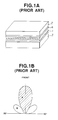
- Fig.1 is a view for explaining the converging action of a prism lens of the prior art.
- Fig.2 is a view for explaining the law of light refraction of a prism lens from the prior art.
- Fig.3 is a view for explaining the critical reflecting angle of a light for a prism lens from the prior art.
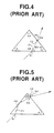
- Fig.4 is a view for explaining the refraction state of a prism lens of the prior art.
- Fig.5 is a view for explaining another refraction state of a prism lens of the prior art.
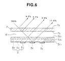
- Fig.6 is a typical conventional liquid crystal display of a transmission back-lighted type.
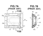
- Fig.7A is a front view of an example of a conventional liquid crystal display.
- Fig.7B is a sectional view along line VIIB-VIIB of Fig.7A.
- Fig.8A is a front view of another example of a conventional liquid crystal display.
- Fig.8B is a sectional view along line VIIIB-VIIIB of Fig.8A.
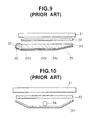
- Fig.9 is a schematic view of a conventional back lighting device of a light-guiding type.
- Fig.10 is a schematic view of a conventional back lighting device of a direct bottom reflecting type.
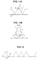
- Fig.11A shows a prism lens embodied in the present invention.
- Fig.11B shows the visual characteristic of the prism lens shown in Fig.11A.
- Fig.12 shows another embodiment of the prism lens, according to the present invention, which is capable of adjusting the visual characteristic by means of a surface area of a flat portion and a quantity of prism portions.
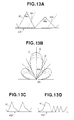
- Fig.13A shows another embodiment of a prism lens according to the present invention.
- Fig.13B shows a visual characteristic by means of a vertex angle, the surface area of a flat portion and a quantity of prism portions.
- Fig.13C shows another embodiment of the prism lens.
- Fig.13D shows another embodiment of the prism lens.
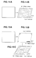
- Fig.14A shows still another embodiment of a prism lens according to the present invention.
- Fig.14B shows a prism lens, which is capable of marking by means of a non-lighting quantity angle of a prism.
- Fig.15A shows another example of a prism lens of Fig.14A.
- Fig.15B shows a display screen at a viewing angle of 36.5° shown in Fig.15A.
- Fig.15C shows a display screen at a viewing angle of 38.6° shown in Fig.15A.
- Fig.16 shows a liquid crystal display embodying the present invention.
- Fig.17 is an enlarged view of a portion A of Fig.16.
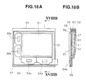
- Fig.18A is a front view of a liquid crystal display embodied in the present invention.
- Fig.18B is a sectional view along line XVIIIB-XVIIIB of Fig.18A.
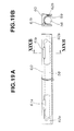
- Fig.19A is a front view of a lamp unit used in the embodiment of liquid crystal display.
- Fig.19B is a sectional view along line XIIB-XIXB of Fig.19A.
- Fig.20 is a view for explaining the construction of a back lighting device embodied in the present invention.
- Fig.21 is an enlarged section of a portion A of Fig.20.
- Fig.22 is a view of another embodiment of a back lighting device according to the present invention.
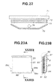
- Fig.23A is a view of still another embodiment of a back lighting device according to the present invention.
- Fig.23B is a sectional view along line XXIIIB-XXIIIB of Fig.23A.
- Fig.24 is an enlarged section of a portion B of Fig.23B.
- Fig.25A is a view of another embodiment of a back lighting device according to the present invention.
- Fig.25B is a view of another embodiment of a back lighting device shown in Fig.25A.
- Fig.26 shows a view angle versus the luminosity of a back lighting device according to the present invention.
- a method for increasing the luminosity of the display light in a specified direction by converging diffused light of the back lighting device by the use of a prism lens.
- the mechanism of a prism lens according to the prior art will be described in detail with reference to the accompanying drawings.
- Figs.1A,1B are views for explaining the converging function of a prism lens:
- Fig.1A is a general construction view of a liquid crystal display and
- Fig.1B shows a view angle characteristic of a prism lens, wherein A and B represent portions of the light's quantity distribution.
- a sheet 1 comprises small assembled pieces of prism lenses.
- Number 2 designates a liquid crystal panel and number 3 designates a back light composed of a light guiding plate, a reflecting plate, a diffusing plate and a light source, e.g. a fluorescent tube, electroluminescence or daylight and number 4 designates a diffusing sheet.
- a light source e.g. a fluorescent tube, electroluminescence or daylight
- number 4 designates a diffusing sheet.
- Fig.2 shows the law of light refraction.
- the formula (2) shows that an incident angle of light is equal to the departure angle if the incident plane and departing plane are parallel to each other.
- Fig.3 shows a critical reflecting angle of light.
- a light ray enters a medium at an incident angle of 90° and refracts at an angle ⁇ limit expressed by the following formula. Therefore, if an incident angle of a light beam exceeds this angle, no refraction can occur and all the light energy is reflected by the interface. This angle is called a critical reflection angle.
- Fig.4 shows the refractive state of a prism lens.
- a light beam enters a medium at an incident angle of ⁇ i and refracts at a refraction angle of ⁇ 1 expressed by the formula (1).
- ⁇ p a vertex angle of a prism lens
- the refracted light beam encounters the boundary of the prism lens at the angle ⁇ 2 expressed by the following formula.
- ⁇ 2 90° - ⁇ 1 - ⁇ p /2
- This departing light beam corresponds to portion A of the quantity of light distributed as shown in Fig.1.
- no-light angle If the departure angle of a light beam exceeds the above-mentioned value, no light appears and brightness is sharply reduced. This critical angle will be called no-light angle.
- Fig.5 shows another refraction state of a prism lens.
- a part of a light beam appears from the prism lens after reflecting therein.
- a light beam enters into the prism at an incident angle ⁇ i and becomes a refracted beam bent at the angle ⁇ 1 to be determined by the formula (1).
- the vertex angle of the prism is denoted by ⁇ p
- This departing light beam corresponds to portion B of the quantity of light distributed as shown in Fig.1B.
- Fig.6 is a typical conventional liquid crystal display of transmission back-lighted type that comprises a liquid crystal panel 5 including a color filter glass 5a, a deflection plate 5b, a black matrix 5c and so on, for obtaining an image transmission light from a white light emitted from a back light (not shown), and a front transparent plate 7 made of acrylic resin and the like and disposed with an air-gap layer 6 on the front side of the liquid crystal panel (opposite to the side facing to the back light).
- the front transparent plate 7 serves to protect the liquid crystal panel 5 against direct application of mechanical force and contamination by dust and dirt.
- the reflectance of light at an interface between two media having different refractive indices has the following expression:
- Reflected light rays are produced thereat at the above-mentioned reflectance.
- the conventional liquid crystal display reflects totally about 23.3% of external incident light from its front surface, that may impair the visibility of an image indicated on the display screen. Particularly, under plenty of external light, the reflected light becomes brighter than the picture image of the liquid crystal display, that may remarkably affect the display image contrast, i.e. impairing its visibility.
- the prevention of light reflection by this thin film having an anti-reflection coating is based on that the anti-reflection coating may cause an incident light beam having a certain wavelength entered thereinto to be reverse in phase to a light beam reflected by rear surface thereof to cancel each other. This eliminates the reflection of the light toward the front surface thereof.
- Increasing the quantity of anti-reflection coatings may suppress reflection of light beams of all wavelengths.
- Figs.7A and 7B show a back lighting unit using a U-shaped fluorescent lamp, wherein IC chips 14a and 14b for a horizontal driver are mounted by TAB (tape automated bonding) on the upper edge and the lower edge, respectively, of a glass plate 12, and IC chips 15a and 15b for a vertical driver are mounted by TAB on the left edge of the glass plate 12.
- the IC chips 14a, 14b and 15a, 15b are connected to a drivers' substrate 16 by means of a member enclosing a liquid crystal display holder 17.
- a lamp unit 13 composed of a U-shaped fluorescent lamp 18, a reflecting plate 19, a diffusing plate 20 and an inverter unit 21 is inserted into the liquid crystal holder 17 from the right side thereof.
- the inverter unit 21 includes a lamp driving circuit and electrically connected to the U-shaped fluorescent lamp 18.
- the fluorescent lamp 18 can be exchanged with a new one after taking out the lamp unit 13 from the holder 17 in the direction shown by the arrows A
- the driver's TAB package is bendable to reduce the size of the screen's frame, but it is difficult to make the U-shaped lamp 18 smaller in diameter, thereby the lamp unit 13 must be thick in size, increasing the total thickness of the liquid crystal display.
- Figs.8A and 8B show a liquid crystal display which uses a straight tube type fluorescent lamp 18 and is similar in construction to the liquid crystal display of Figs.7A and 7B.
- IC chips 14a, 14b for a horizontal driver, IC chips 15a, 15b for a vertical driver and a drivers' substrate 16 are mounted on the same plane with a liquid crystal panel 11 to reduce the thickness of the liquid crystal display.
- the straight tube-type fluorescent lamp 18 may have a reduced diameter. This enables the lamp unit 13 to be thinner thereby assuring the possibility of reducing the thickness of the liquid crystal display.
- Fig s.9 and 10 are construction views of conventional transmission type liquid crystal displays which are provided with, respectively, a back lighting device of a light-guiding type (Fig.9) and a back lighting device causing bottom reflection (Fig.10).
- a liquid crystal panel 31 a reflector 32, a diffusing plate 33, a light guiding plate 34 having a lateral inlet surface 34a, a front surface 34b and a bottom surface 34c, a reflecting plate 35, a fluorescent lamp 36 and a reflecting plate 37.
- Fig.9 there is illustrated the back lighting device of a light-guiding type wherein light rays from the fluorescent lamp 36 enter directly or, after being reflected at the reflector 32, into the light guiding plate 34, through the lateral inlet surface 34a, then repeatedly reflected at the bottom surface 34c and the front surface 34b thereof and then are emitted as homogeneous back lighting rays directed upward from the front surface thereof.
- the reflecting plate 35 At the back of the light guiding plate 34 is placed the reflecting plate 35 by which light rays, leaking from the bottom surface of the light-guiding plate 34, are reflected and returned into the light-guiding plate 34, thereby the light rays can be effectively used.
- Light rays emitted from the light-guiding plate 34 are diffused in the diffusing plate 33 into homogeneous diffused light having limited directionality and which illuminates the liquid crystal panel 31.
- light rays from the light-guiding plate 34 have directionality A with peak lighting obtainable when observed from a lower position, i.e., the directionality does not correspond to the view angle D of the liquid crystal panel. This means that the maximum lighting on the display cannot be obtained when observing the display screen from the front.
- the light-guiding plate 34 is generally placed at the front surface with the diffusing plate 33 to obtain homogeneous light rays of a relatively small directionality B' as shown in Fig.26.
- Another similar example of the prior art is a back lighting device which has a converging plate placed at the front surface of the light-guiding plate 34 and has a diffusing plate 33 placed on the converging plate.
- a back lighting device which has a converging plate placed at the front surface of the light-guiding plate 34 and has a diffusing plate 33 placed on the converging plate.
- All the components and a holder for the back lighting device are provided with ribs and assembled on the holder through the use of ribs. However, since the components are thin and not attached to each other, they may become displaced in the course of assembling thereby causing uneven luminosity by the back light rays.
- FIG.10 Another typical example of the prior art is a direct bottom-reflecting type back lighting device which may employ a variety of straight tubular, U-shaped and W-shaped lamps.
- the device shown in Fig.10 includes a straight tubular type fluorescent lamp.
- Back light rays from the lamp 36 are injected directly or, after reflection by a reflecting plate 37, into a diffusing plate 33 through which homogeneously diffused light rays are irradiated to a liquid crystal display panel 31.
- Figs.112 and 113 are views, respectively, showing a refraction characteristic Fig.11A and a view angle characteristic Fig.11B of a prism lens embodied in the present invention.
- numerals 41 and 42 designate a prism portion and a flat portion, respectively, of a prism lens and numeral 43 designates the prism lens itself.
- A represents a portion of a view angle characteristic of a prism portion and B represents a portion of a view angle characteristic of a flat portion and C represents a portion of a view angle characteristic of the whole system.
- a flat portion 42 is provided on the top of a prism portion 41, however, the same effect can be achieved by providing a flat portion 42 between the prism portions 41 or on the top of the prism portions and between the prism portions.
- the flat portion at which an incident angle of a light beam equal to its departure angle and ⁇ 0 is smaller than 90° so therefore the light beam appears at the angle ⁇ 0 .
- the intensity of the light beam, directed in the direction of angle ⁇ 0 can be adjusted by means of a duty ratio of the flat portioned area to the prism lens area.
- a plurality of prism portions 41 are arranged with flat portions 42 each between two prism portions, wherein the view angle characteristic of the prism lens unit can be adjusted by means of the flat area of the portions and the number of prism portions.
- the non-lighting quantity angle is 35.6° degrees according to the following formula:
- Figs.13A to 13D are construction views of another embodiment of the prism lens according to the present invention.
- numerals 41 and 43 designate a prism portion and a prism lens.
- A represents a portion of a view angle characteristic of a prism P1 and B represents a portion of a view angle characteristic of a prism P2 and C represents a portion of a view angle characteristic of the whole system.
- the design of a prism lens unit may be determined by the view angle characteristics and the necessary visual field angles of a liquid crystal display and a back lighting system.
- a single prism lens sharply loses its luminosity.
- the provision of prism lenses having different vertex angles enables the light beam to pass at the direction of angle ⁇ 01(2) .
- the intensity of the light beam directed in the angular direction ⁇ 01(2) can be adjusted by means of a duty ratio of the vertex angles and the area of the prism portions.
- Fig.13C shows a lens unit having different vertex angles at each prism portion.
- a plurality of prism portions are arranged with the prism portions each having a different vertex angle between two prism portions wherein the view angle, characteristic of the prism lens unit, can be adjusted by means of the prism portions' area and the number of prism portions.
- the non-lighting quantity angles are calculated as follows:
- the combination of the two prisms, having different vertex angles, may generally remove the non-lighting portion.
- Figs. 14A and 14B show an example for relieving a character or symbol against a background on the LC display screen only at a specified viewing angle by means of providing a flat portion on a prism sheet.
- the non-lighting quantity angles are calculated as follows:
- Fig.15A to 15C show examples for giving a plurality of non-lighting quantity angles to a prism lens unit by providing a prism having a different vertex angle on the part of the prism sheet.
- Fig.15B which includes a prism having a vertex angle of 70°
- normally invisible symbols ⁇ ⁇ ⁇ ⁇ become visible only at a viewing angle of 29.3°
- Fig.15C having a vertex angle of 100° normally invisible symbols ⁇ ⁇ ⁇ ⁇ become visible only at a viewing angle of 38.6°. In both cases such visibility is obtained by making the corresponding portions flat.
- Fig.16 shows a back-lighted transmission type liquid crystal display, by means of example, according to the present invention.
- a liquid crystal display comprises a liquid crystal panel 44 which includes a color filter glass 44a, a deflecting plate 44b and a black matrix 44c and so on for obtaining an image transmitting light from a white light emitted by a back light (not shown), and a front transparent plate 45 made of acrylic resin and the like and closely attached to the front surface of the liquid crystal panel (opposite to the side facing to the back light).
- the front transparent plate 45 serves to protect the liquid crystal panel 44 against direct application of mechanical force and contamination with dust and dirt.
- the front transparent plate 45 and the deflecting plate 44b of liquid crystal panel 44 are bonded to each other with adhesive 48 of which the refractive index is nearly equal to the deflecting plate 44b and the front transparent plate 45.
- Fig.17 is an enlarged view of the portion A of Fig.16, showing a front transparent panel 43 which has a non-glaring uneven surface portion 45a for converting reflected light to scattered and is coated at the uneven surface with a anti-reflection layer 46 of several angstroms in thickness.
- the reflection of external light at the front surface of the liquid crystal display is as follows:
- the external light reflection at a front (incident) surface 45a of the front transparent plate 45 is reduced to an amount of about 0.1% of incident light by means of the antireflection film 46.
- No reflection occurs at a surface 45a and a rear surface 45b of the front transparent plate 45 because the front transparent plate 45 bonded to the deflecting plate with the adhesive having nearly equal refractive index that the two plates have.
- an aperture ratio of picture elements is 40% and the transmittance of the color filter glass is 95%, about 11.6% of the incident light is reflected by the surface 44c 1 of the black matrix 44c.
- Total reflection of external incident light at the front surface of the liquid crystal display corresponds to about 11.8% of the external incident light and this figure means that the reflection of external light is reduced to 1/2 in comparison with the previously described conventional liquid crystal display.
- the reflection of light at a front surface 44a 1 (the boundary on the deflecting plate 44b) of the color filter glass 44a is negligible since the refractive index of color filter 44a is nearly equal to that of the deflecting plate 44b.
- the front transparent plate 45 prevents the reflection of external incident light by its antireflection film 46 and assures the improved visibility of display screen even at a bright place by scattering the reflected external light by the irregular surface portion on the antireflection coating.
- Fig.18A and 18B are construction views of a liquid crystal display embodying the present invention, which is comprised of a thin-film transistor (TFT), a glass plate 52, a liquid crystal holder 53, IC chips for a horizontal driver 54a, 54b, IC chips for a vertical driver 55a a driver's substrate 56, a reflecting plate 57, a straight tube fluorescent lamp 58, a lamp reflector 59, a lamp holder 60, a diffusing plate 61, a converging plate 62, a light-guiding plate 63.
- TFT thin-film transistor
- numeral 51 designates a flat liquid crystal panel which comprises a glass plate 52 filled with liquid crystal and having a thin-film transistor (TFT) composing picture elements, a color filter RGB, black matrices between picture elements and bus lines to each picture element, and a driver substrate 56 on which IC chips 54b, 54b for a horizontal driver and IC chips 55a, 55b for a vertical driver are mounted.
- the IC chips 54a and 54b are disposed at the lower edge of the glass plate 52 and the IC chips 55a and 55b are disposed at the left side edge of the glass plate 52. These IC chips are electrically connected with the TFT picture elements of the glass plate 52.
- the lamp unit contains a straight tube-type fluorescent lamp 58 and is disposed on a side surface (the upper surface in Fig.18B) of a back lighting unit.
- a lamp holder 60 holds the straight tube-type fluorescent lamp 58, a lamp reflector 59 enclosing the lamp, as shown in detail in Figs.19A and 19B. It also includes safety thermal fuses 61a, 61b. Lead wires of the lamp 58 through the thermal fuses 61a, 61b are electrically connected to electrode terminals 62a and 62b provided at the external surface of the lamp holder 60.
- the back light unit is composed of a light-guiding plate 63 for receiving therein light rays from the fluorescent lamp 58 through the lateral surface thereof and uniformly propagating and diffusing the light over a whole display screen, a reflecting plate 57 disposed on the rear surface of the light-guiding plate 63 so as to reflect the light therefrom, a diffusing plate 61 for diffusing light from the front surface of the light-guiding plate 63 and a converging plate 62 for converging light from the diffusing plate according to a directional characteristic substantially corresponding to a view angle characteristic of a liquid crystal panel 51. These components are disposed all in flat layers on the rear surface of the glass plate 52.
- liquid crystal panel 51 The above-mentioned liquid crystal panel 51, the lamp unit and the back light unit are held by a liquid crystal display holder 53.
- the reflecting plate 57 reflects light rays leaking from the bottom surface of the light-guiding plate 63 and injects them again into the light-guiding plate 63.
- Light rays pass through the front surface of the light-guiding plate 63 and enter into the converging plate 62 whereby they are further converged in the direction toward the front surface of the liquid crystal panel 51. Consequently, the light rays from the converging plate 62 can have a directional characteristic substantially corresponding to the view angle characteristic of the liquid crystal panel, remarkably increasing the front axial luminosity of the display screen.
- the lamp unit integrally holding the fluorescent lamp 58 together with the lamp reflector 59 can be removably secured to the liquid crystal display holder 60. Therefore, when the lamp 58 reaches the end of its useful life or is damaged, anyone can easily replace the entire lamp unit with a new one.
- Fig.20 is a construction view of a light-guiding type back lighting device embodying the present invention, which is comprised of a liquid crystal panel 71, a converging plate 72, a diffusing plate 73, a light-guiding plate 74 having a lateral inlet portion 74a, a front surface 74b and a bottom surface 74c, a reflecting plate 75, a lamp 76 and a reflector 77.
- the reflecting plate 75 At the back of the light-guiding plate 74 is placed the reflecting plate 75 by which light rays, leaking from the bottom surface of the light-guiding plate 74 are reflected and returned into the light-guiding plate 74, thereby light rays can be effectively used.
- Light rays emitted from the light-guiding plate 74 are diffused in the diffusing plate 73 to produce homogeneous by diffused light having small directionality which illuminates the liquid crystal panel 71.
- This embodiment differs from the conventional back lighting device shown in Fig.9 in that a prism-like converging plate 72 is provided between the liquid crystal panel 71 and the diffusing plate 73.
- a prism-like converging plate 72 is provided between the liquid crystal panel 71 and the diffusing plate 73.
- back lighting rays directed upward and downward at an angle are converged in an axial direction by the prism-like converging plate 72. Consequently, the embodiment may have the view angle characteristic C shown in Fig.26, which is similar in directionality with characteristic D of the liquid crystal panel and may have a remarkably increased axial luminosity in comparison with the view angle characteristics B and B', shown in Fig.26, of the conventional diffusing plates.
- converging plate 72 having prism-like grooves shown in the enlarged section in Fig.21, in a horizontal direction is effective for obtaining converging characteristics in a vertical view angle direction. If the spacing between prism-like grooves of the converging plate 72 is substantially equal to that of the vertical picture elements of the liquid crystal panel 71, there may occur periodical uneven luminosity which appears as more fringes on an image of the liquid crystal display.
- the prism-like grooves of the converging plate 72 shall be arranged at intervals of not more than 50 ⁇ m, thereby the possibility of the occurrence of moire fringes can be eliminated.
- Fig.22 is a construction view of a back lighting device of a direct bottom-reflecting type wherein a reflecting plate is designated by numeral 7B and other components similar to those of Fig.20 shown with like numerals.
- the embodiment differs from the prior art shown in Fig.10 in that a converging plate having prism-like grooves 72 arranged at narrow intervals is placed on a diffusing plate 73.
- the embodiment may have the view angle characteristic C shown in Fig.26, which is similar in direction to characteristic D of the liquid crystal panel and may attain a remarkable improvement of axial luminosity similar to the above-mentioned case.
- Figs.23A and 23B are construction views of a back lighting device using a welded light-guiding unit, and Fig.24 shows the portion B of Fig.23B in an enlarged scale.
- a converging plate 81 there are shown a converging plate 81, a diffusing plate 82 having a protrusion 82a, a light guide plate 83 having an inlet portion 83a, a front surface 83b and a bottom surface 83c, a reflecting plate 84, and image area of a liquid crystal panel 85, a reflector 86, a lamp 87, a liquid crystal panel 88, a back lighting unit 89 with a welded portion 89a and protrusions 89b, 89c, and a reflecting element 90.
- Light rays from the fluorescent lamp 87 are injected, directly or after reflection by the reflector 86, into the diffusing plate 83 through the inlet portion 83a thereof, wherein they repeatedly reflect at the bottom surface 83c and the front surface 83b and then exit from the front surface 83b.
- the reflecting plate 84 reflects light rays leaking from the bottom surface of the light guiding plate 83 and again injects them into the light guiding plate 83.
- the light rays from the light guiding plate 83 enter into the converging plate 82 wherein they are diffused to homogeneous light rays having no direction.
- the converging plate 81 is provided which enables light rays of conventional view angle characteristic B', substantially even as shown in Fig.26, to have a view angle characteristic C similar to that of the liquid crystal panel, causing upward, downward and diagonal light rays to converge in the front axial direction.
- Such light rays assure the increased front luminosity of an image on the liquid crystal panel.
- the converging plate having prism-like grooves in the horizontal direction, is effective for obtaining the required converging characteristic in a vertical visual, angled direction.
- the prism-like grooves of the converging plate when the picture elements of the liquid crystal panel are arranged, for example, at intervals of about 200 ⁇ m in a vertical direction, the prism-like grooves of the converging plate shall be arranged at intervals of not more than 50 ⁇ m, thereby eliminating moire fringes.
- the present invention also proposes a method for welding the above-mentioned components to form an integrated unit which will be described in detail as follows:
- a light guiding plate 83 and a diffusing plate 82 each made of acrylic resin having a thermal expansion coefficient of 6 to 7 x 10 -5 cm/cm/°C
- a converging plate 81 made of polycarbonate resin, having a thermal expansion coefficient of about 2 x 10 -5 cm/cm/°C and a reflecting plate having a thermal expansion coefficient of about 1.8 x 10 -5 cm/cm/°C are welded with each other at the periphery to form one unit having an area size equal to a 4-inch display screen.
- the unit in operation at temperatures of 0 to 50°C may be subjected to thermal deformation by about 0.2 to 0.3mm thereby causing on uneven luminosity of back light.
- the present invention provides such a method as shown in Fig.23A the back light unit 89 is made in a size larger than the liquid crystal display screen 88 by about 3mm at each peripheral edge and its components each are welded at one of two locating protrusions 89b, 89c provided for mounting to a back-lighting holder 91 as shown in Fig.25B.
- the proposed method may eliminate the possibility of causing an uneven luminosity in the weld portion of the unit on the display screen as well as eliminating the possibility of the occurrence of uneven luminosity due to the thermal deformation of the components since each component can freely expand and shrink.
- One of the proposed methods is to adhesively attach reflecting plates 83d,83e respectively to both side surfaces of a lighting guide 83 as shown in Fig.25A.
- the other method is such that the lighting guide plate 83 is enclosed at all surfaces by opposing surfaces of other components and by surfaces, except for upper surface 91d for mounting a liquid crystal panel, of a back lighting holder 91 shown in Fig.25B. All opposed surfaces of the components are made of or coated with a material of a high reflective power.
- Fig.24 shows a portion B of Fig.23B to an enlarged scale.
- the portion between a lamp 87 and a light inlet surface 83a of a light guiding plate 83 is enclosed by a reflector 86 and a reflecting plate 84, but, as shown in Fig.23B, a diffusing plate 82 has an end 82a protruding in the direction of the reflector 86. Therefore light rays emitted by the lamp 87 may leak through the protruding end 82a of the diffusing plate 82 and travel toward the liquid crystal panel 85 causing uneven luminosity on the display screen and resulting in a loss of illumination. Accordingly, a light reflecting element 90 is adhesively attached to the lower surface of the protrusion 82a of the diffusing plate 82 to prevent the leakage of light rays therethough.
Abstract

Description


Claims (1)
- A liquid crystal display provided with a back light, characterized by:characterized in that an integrated-circuit chip 54a, 54b for a horizontal driver and an integrated-circuit chip 55a, 55b for a vertical driver are mounted each on one of two adjacent peripheral edges of the liquid crystal panel 51 and the lamp unit is mounted on one of two remaining peripheral edges of the liquid crystal panel 51, whereon no IC chip is mounted.a display means for displaying characters and graphics, said means including a display portion comprising at least a liquid crystal panel 51;an illuminating means for illuminating the display portion of the liquid crystal panel 51, said illuminating means comprising a lamp unit integrally formed of at least a lamp 58 and a lamp reflector 59 for reflecting light rays from the lamp 58 in one direction, and a back light unit integrally formed of a light-guiding plate 63 for receiving therein light rays of the lamp 58 through a lateral surface thereof and for uniformly propagating and diffusing the light rays therein, and a reflecting plate 57 disposed on the rear surface of the light-guiding plate 63 to reflect light rays from the rear surface of the light-guiding plate 63; and a diffusing plate 61 disposed on the front surface of the light-guiding plate 63 to diffuse light rays from the front surface of the light-guiding plate 63;a converging means 62 for converging light rays from the illuminating means at the display portion of the liquid crystal panel 51; anda liquid crystal display holder 53 for holding the lamp unit, the back light unit and the liquid crystal panel 51 in definite positions,
Applications Claiming Priority (13)
| Application Number | Priority Date | Filing Date | Title |
|---|---|---|---|
| JP16529892 | 1992-06-01 | ||
| JP4165298A JP2931480B2 (en) | 1992-06-01 | 1992-06-01 | Light collecting device used for light source device |
| JP165298/92 | 1992-06-01 | ||
| JP23455692 | 1992-09-02 | ||
| JP234556/92 | 1992-09-02 | ||
| JP23455692 | 1992-09-02 | ||
| JP4345012A JPH06194652A (en) | 1992-12-25 | 1992-12-25 | Liquid crystal display device |
| JP34501292 | 1992-12-25 | ||
| JP345012/92 | 1992-12-25 | ||
| JP27457/93 | 1993-01-21 | ||
| JP02745793A JP3263460B2 (en) | 1992-09-02 | 1993-01-21 | Backlight device |
| JP2745793 | 1993-01-21 | ||
| EP93304260A EP0573268B1 (en) | 1992-06-01 | 1993-06-01 | Liquid crystal display |
Related Parent Applications (1)
| Application Number | Title | Priority Date | Filing Date |
|---|---|---|---|
| EP93304260.8 Division | 1993-06-01 |
Publications (3)
| Publication Number | Publication Date |
|---|---|
| EP0908757A2 true EP0908757A2 (en) | 1999-04-14 |
| EP0908757A3 EP0908757A3 (en) | 1999-06-16 |
| EP0908757B1 EP0908757B1 (en) | 2003-09-03 |
Family
ID=27458690
Family Applications (2)
| Application Number | Title | Priority Date | Filing Date |
|---|---|---|---|
| EP98204145A Expired - Lifetime EP0908757B1 (en) | 1992-06-01 | 1993-06-01 | Liquid crystal display |
| EP93304260A Expired - Lifetime EP0573268B1 (en) | 1992-06-01 | 1993-06-01 | Liquid crystal display |
Family Applications After (1)
| Application Number | Title | Priority Date | Filing Date |
|---|---|---|---|
| EP93304260A Expired - Lifetime EP0573268B1 (en) | 1992-06-01 | 1993-06-01 | Liquid crystal display |
Country Status (8)
| Country | Link |
|---|---|
| US (2) | US5467208A (en) |
| EP (2) | EP0908757B1 (en) |
| CN (1) | CN1043082C (en) |
| AU (3) | AU665680B2 (en) |
| CA (1) | CA2097109C (en) |
| DE (3) | DE69333355T2 (en) |
| ES (3) | ES2206831T3 (en) |
| MY (3) | MY112201A (en) |
Cited By (2)
| Publication number | Priority date | Publication date | Assignee | Title |
|---|---|---|---|---|
| EP1434082A1 (en) * | 2000-01-11 | 2004-06-30 | Kabushiki Kaisha Toshiba | Multidomain liquid crystal display device with two liquid crystal layers |
| US8686624B2 (en) | 2000-04-21 | 2014-04-01 | Semiconductor Energy Laboratory Co., Ltd. | Self-light emitting device and electrical appliance using the same |
Families Citing this family (118)
| Publication number | Priority date | Publication date | Assignee | Title |
|---|---|---|---|---|
| US6002829A (en) | 1992-03-23 | 1999-12-14 | Minnesota Mining And Manufacturing Company | Luminaire device |
| JP3136200B2 (en) * | 1992-07-22 | 2001-02-19 | 株式会社日立製作所 | Liquid crystal display |
| US5818555A (en) * | 1993-11-05 | 1998-10-06 | Enplas Corporation | Surface light source device |
| US5521725A (en) * | 1993-11-05 | 1996-05-28 | Alliedsignal Inc. | Illumination system employing an array of microprisms |
| US6129439A (en) * | 1993-11-05 | 2000-10-10 | Alliedsignal Inc. | Illumination system employing an array of multi-faceted microprisms |
| JPH07191618A (en) * | 1993-12-27 | 1995-07-28 | Satoshi Inoue | Display device formed by using light transmission plate |
| US5982540A (en) * | 1994-03-16 | 1999-11-09 | Enplas Corporation | Surface light source device with polarization function |
| JPH07270603A (en) * | 1994-03-29 | 1995-10-20 | Enplas Corp | Optical control member |
| DE19521254A1 (en) * | 1994-06-24 | 1996-01-04 | Minnesota Mining & Mfg | Display system with brightness boosting film |
| JP2742880B2 (en) * | 1994-08-12 | 1998-04-22 | 大日本印刷株式会社 | Surface light source, display device using the same, and light diffusion sheet used for them |
| JPH10506500A (en) * | 1994-09-27 | 1998-06-23 | ミネソタ マイニング アンド マニュファクチャリング カンパニー | Brightness control film |
| US5657408A (en) * | 1994-12-23 | 1997-08-12 | Alliedsignal Inc. | Optical device comprising a plurality of units having at least two geometrically-differentiated tapered optical waveguides therein |
| JP3920364B2 (en) * | 1994-12-28 | 2007-05-30 | 株式会社エンプラス | Two-beam generation method and two-beam generation type surface light source device |
| CA2212223C (en) * | 1995-03-03 | 2007-03-20 | David L. Wortman | Light directing film having variable height structured surface and light directing article constructed therefrom |
| JP3429388B2 (en) * | 1995-03-31 | 2003-07-22 | 株式会社エンプラス | Surface light source device and liquid crystal display |
| KR100257969B1 (en) * | 1995-04-11 | 2000-06-01 | 제럴드 엘. 클라인 | Daylight readable liquid crystal display |
| JP2768313B2 (en) * | 1995-06-13 | 1998-06-25 | 日本電気株式会社 | Reflective liquid crystal display |
| US7108414B2 (en) | 1995-06-27 | 2006-09-19 | Solid State Opto Limited | Light emitting panel assemblies |
| US5613751A (en) | 1995-06-27 | 1997-03-25 | Lumitex, Inc. | Light emitting panel assemblies |
| US6712481B2 (en) | 1995-06-27 | 2004-03-30 | Solid State Opto Limited | Light emitting panel assemblies |
| JP3548812B2 (en) * | 1995-08-11 | 2004-07-28 | オムロン株式会社 | Surface light source device, planar optical element used in the device, and image display device using the device |
| US5938312A (en) * | 1995-09-22 | 1999-08-17 | Rohm Co., Ltd. | Surface mounting type light emitting display device, process for making the same, and surface mounting structure of the same |
| US6011602A (en) * | 1995-11-06 | 2000-01-04 | Seiko Epson Corporation | Lighting apparatus with a light guiding body having projections in the shape of a trapezoid |
| US5895115A (en) * | 1996-01-16 | 1999-04-20 | Lumitex, Inc. | Light emitting panel assemblies for use in automotive applications and the like |
| US5917664A (en) * | 1996-02-05 | 1999-06-29 | 3M Innovative Properties Company | Brightness enhancement film with soft cutoff |
| US6072551A (en) * | 1996-02-14 | 2000-06-06 | Physical Optics Corporation | Backlight apparatus for illuminating a display with controlled light output characteristics |
| US5838403A (en) * | 1996-02-14 | 1998-11-17 | Physical Optics Corporation | Liquid crystal display system with internally reflecting waveguide for backlighting and non-Lambertian diffusing |
| US5919551A (en) * | 1996-04-12 | 1999-07-06 | 3M Innovative Properties Company | Variable pitch structured optical film |
| JP3769327B2 (en) * | 1996-07-23 | 2006-04-26 | 大日本印刷株式会社 | Prism lens sheet, backlight system and liquid crystal display device |
| US5854872A (en) * | 1996-10-08 | 1998-12-29 | Clio Technologies, Inc. | Divergent angle rotator system and method for collimating light beams |
| DE59713046D1 (en) * | 1996-12-04 | 2010-11-18 | Siteco Beleuchtungstech Gmbh | Interior light |
| KR100229615B1 (en) * | 1997-01-28 | 1999-11-15 | 구자홍 | Lcd device |
| CN1126001C (en) * | 1997-02-13 | 2003-10-29 | 联合讯号公司 | Illumination system with light recycling to enhance brightness |
| US5913594A (en) * | 1997-02-25 | 1999-06-22 | Iimura; Keiji | Flat panel light source device and passive display device utilizing the light source device |
| JP3615355B2 (en) * | 1997-06-04 | 2005-02-02 | 株式会社エンプラス | Sidelight type surface light source device and light guide plate |
| US6036322A (en) | 1997-12-01 | 2000-03-14 | Reflexite Corporation | Multi-orientation retroreflective structure |
| KR100290775B1 (en) | 1997-12-17 | 2001-06-01 | 박종섭 | Back light unit without mold frame of liquid crystal display |
| US6052165A (en) * | 1997-12-22 | 2000-04-18 | Philips Electronics North America Corporation | Reflective liquid crystal display (LCD) device having an internal reflection reducer |
| US6473220B1 (en) | 1998-01-22 | 2002-10-29 | Trivium Technologies, Inc. | Film having transmissive and reflective properties |
| DE69939647D1 (en) | 1998-02-18 | 2008-11-13 | Minnesota Mining & Mfg | OPTICAL FILM |
| JP3839998B2 (en) * | 1998-10-28 | 2006-11-01 | シャープ株式会社 | Backlight |
| AU2609800A (en) | 1999-01-14 | 2000-08-01 | Minnesota Mining And Manufacturing Company | Optical sheets suitable for spreading light |
| US7364341B2 (en) * | 1999-02-23 | 2008-04-29 | Solid State Opto Limited | Light redirecting films including non-interlockable optical elements |
| US6827456B2 (en) | 1999-02-23 | 2004-12-07 | Solid State Opto Limited | Transreflectors, transreflector systems and displays and methods of making transreflectors |
| US6752505B2 (en) | 1999-02-23 | 2004-06-22 | Solid State Opto Limited | Light redirecting films and film systems |
| US6845212B2 (en) * | 1999-10-08 | 2005-01-18 | 3M Innovative Properties Company | Optical element having programmed optical structures |
| US7046905B1 (en) * | 1999-10-08 | 2006-05-16 | 3M Innovative Properties Company | Blacklight with structured surfaces |
| US6447135B1 (en) | 1999-10-08 | 2002-09-10 | 3M Innovative Properties Company | Lightguide having a directly secured reflector and method of making the same |
| US6356391B1 (en) | 1999-10-08 | 2002-03-12 | 3M Innovative Properties Company | Optical film with variable angle prisms |
| US6581286B2 (en) | 2000-04-05 | 2003-06-24 | 3M Innovative Properties Company | Method of making tool to produce optical film |
| US7633471B2 (en) | 2000-05-12 | 2009-12-15 | Semiconductor Energy Laboratory Co., Ltd. | Light-emitting device and electric appliance |
| US6639349B1 (en) * | 2000-06-16 | 2003-10-28 | Rockwell Collins, Inc. | Dual-mode LCD backlight |
| KR20020001594A (en) * | 2000-06-26 | 2002-01-09 | 가마이 고로 | Light pipe, plane light source unit and reflection type liquid-crystal display device |
| US8054416B2 (en) * | 2000-08-15 | 2011-11-08 | Reflexite Corporation | Light polarizer |
| JP3544349B2 (en) * | 2000-09-27 | 2004-07-21 | シャープ株式会社 | Liquid crystal display |
| JP2002139630A (en) * | 2000-10-31 | 2002-05-17 | Alps Electric Co Ltd | Light transmission plate, method for manufacturing the same, surface light-emitting device and liquid crystal display |
| KR100658066B1 (en) * | 2000-11-02 | 2006-12-15 | 비오이 하이디스 테크놀로지 주식회사 | Surrounding prism band in lcd |
| KR100765304B1 (en) * | 2001-02-21 | 2007-10-09 | 삼성전자주식회사 | Backlight assembly and liquid crystal display device having the same |
| US7070315B2 (en) * | 2001-04-12 | 2006-07-04 | Samsung Electronics Co., Ltd. | Backlight unit for liquid crystal display device |
| AU2002327420B2 (en) * | 2001-08-06 | 2007-05-31 | Mei, Incorporated | Document validator subassembly |
| CN100403107C (en) * | 2001-12-11 | 2008-07-16 | 索尼公司 | LCD appts. |
| JP2006500601A (en) * | 2002-02-27 | 2006-01-05 | イノヴェイティヴ ソリューションズ アンド サポート インコーポレイテッド | Improved low reflection flat panel display |
| US7345824B2 (en) | 2002-03-26 | 2008-03-18 | Trivium Technologies, Inc. | Light collimating device |
| US7595934B2 (en) | 2002-03-26 | 2009-09-29 | Brilliant Film Llc | Integrated sub-assembly having a light collimating or transflecting device |
| KR100878206B1 (en) * | 2002-08-13 | 2009-01-13 | 삼성전자주식회사 | Optical sheet and back light assembly using the same and liquid crystal display device using the same |
| US6974235B2 (en) * | 2002-10-25 | 2005-12-13 | Acuity Brands, Inc. | Prismatic structures having shaped surfaces |
| US7236217B2 (en) * | 2003-01-16 | 2007-06-26 | 3M Innovative Properties Company | Package of optical films with zero-gap bond outside viewing area |
| KR20040074789A (en) * | 2003-02-19 | 2004-08-26 | 삼성전자주식회사 | Backlight assembly and liquid crystal display having the same |
| US7573550B2 (en) * | 2003-05-20 | 2009-08-11 | Brilliant Film, Llc | Devices for use in non-emissive displays |
| US7413336B2 (en) * | 2003-08-29 | 2008-08-19 | 3M Innovative Properties Company | Adhesive stacking for multiple optical films |
| US7142767B2 (en) * | 2003-12-31 | 2006-11-28 | 3M Innovative Properties Company | Scratch-resistant light directing films |
| US7147358B2 (en) * | 2003-12-31 | 2006-12-12 | 3M Innovative Properties Company | Cover removal tab for optical products |
| JP4845893B2 (en) * | 2004-01-20 | 2011-12-28 | シャープ株式会社 | Directional backlight and multi-view display devices |
| KR101075232B1 (en) * | 2004-02-06 | 2011-10-20 | 삼성전자주식회사 | Light guide plate, backlight unit, liquid crystal display and manufacturing method of the light guide plate |
| TWI313377B (en) * | 2004-03-16 | 2009-08-11 | Innolux Display Corp | Liquid crystal display device |
| US20050238852A1 (en) * | 2004-04-23 | 2005-10-27 | Naoki Nakayama | Optical products for displays |
| CN100381904C (en) * | 2004-05-10 | 2008-04-16 | 辅祥实业股份有限公司 | Full run-down type backlight source module of using control of plane function |
| JP2006156332A (en) * | 2004-10-28 | 2006-06-15 | Alps Electric Co Ltd | Light guide plate, surface light emitting device using the same, and liquid crystal display device using the same |
| US7367705B2 (en) | 2004-11-04 | 2008-05-06 | Solid State Opto Limited | Long curved wedges in an optical film |
| KR100580655B1 (en) * | 2004-11-06 | 2006-05-16 | 삼성전자주식회사 | Method for fabricating an one-way transparent optical system |
| US7163308B2 (en) * | 2004-11-22 | 2007-01-16 | Ferrari John S | Hand worn illuminated framework |
| US7278771B2 (en) * | 2004-11-22 | 2007-10-09 | 3M Innovative Properties Company | Optical film |
| KR101114854B1 (en) * | 2004-12-24 | 2012-03-07 | 엘지디스플레이 주식회사 | A backlight unit |
| US7339635B2 (en) * | 2005-01-14 | 2008-03-04 | 3M Innovative Properties Company | Pre-stacked optical films with adhesive layer |
| JP2006330536A (en) * | 2005-05-30 | 2006-12-07 | Sanyo Epson Imaging Devices Corp | Liquid crystal display device |
| KR101255296B1 (en) * | 2005-06-29 | 2013-04-15 | 엘지디스플레이 주식회사 | Prims sheet and back light unit using the same |
| US7777832B2 (en) * | 2005-11-18 | 2010-08-17 | 3M Innovative Properties Company | Multi-function enhancement film |
| US7499206B1 (en) | 2005-12-09 | 2009-03-03 | Brian Edward Richardson | TIR light valve |
| US8409088B2 (en) | 2006-01-18 | 2013-04-02 | Invuity, Inc. | Retractor illumination system |
| JP5352956B2 (en) * | 2006-02-14 | 2013-11-27 | セイコーエプソン株式会社 | Liquid crystal device, method for manufacturing liquid crystal device, projector and electronic apparatus |
| US8047987B2 (en) | 2006-05-26 | 2011-11-01 | Invuity, Inc. | Blade insert illuminator |
| EP2071392A4 (en) | 2006-09-28 | 2009-09-23 | Sharp Kk | Liquid crystal display panel and liquid crystal display apparatus |
| JP2008146025A (en) * | 2006-11-15 | 2008-06-26 | Sumitomo Chemical Co Ltd | Light diffuser plate, surface light source device, and liquid crystal display apparatus |
| KR20100037104A (en) | 2007-06-22 | 2010-04-08 | 쓰리엠 이노베이티브 프로퍼티즈 컴파니 | Systems and methods for controlling backlight output characteristics |
| US8088066B2 (en) | 2007-10-24 | 2012-01-03 | Invuity, Inc. | Blade insert illuminator |
| US20090147361A1 (en) * | 2007-12-07 | 2009-06-11 | 3M Innovative Properties Company | Microreplicated films having diffractive features on macro-scale features |
| US8226253B2 (en) | 2008-02-27 | 2012-07-24 | Lubart Neil D | Concentrators for solar power generating systems |
| KR101260839B1 (en) * | 2008-04-16 | 2013-05-06 | 엘지디스플레이 주식회사 | Backlight unit and Liquid crystal display module having the same |
| JP2010205713A (en) * | 2008-06-27 | 2010-09-16 | Seiko Instruments Inc | Lighting device, and display device using the same |
| US8462292B2 (en) | 2008-07-31 | 2013-06-11 | Rambus Delaware Llc | Optically transmissive substrates and light emitting assemblies and methods of making same, and methods of displaying images using the optically transmissive substrates and light emitting assemblies |
| US11382711B2 (en) | 2008-08-13 | 2022-07-12 | Invuity, Inc. | Cyclo olefin polymer and copolymer medical devices |
| JP2012514835A (en) | 2009-01-02 | 2012-06-28 | ラムバス・インターナショナル・リミテッド | Optical system for light guide with control output |
| US8272770B2 (en) | 2009-01-02 | 2012-09-25 | Rambus International Ltd. | TIR switched flat panel display |
| US8152352B2 (en) * | 2009-01-02 | 2012-04-10 | Rambus International Ltd. | Optic system for light guide with controlled output |
| US20100315836A1 (en) * | 2009-06-11 | 2010-12-16 | Brian Edward Richardson | Flat panel optical display system with highly controlled output |
| US8152318B2 (en) | 2009-06-11 | 2012-04-10 | Rambus International Ltd. | Optical system for a light emitting diode with collection, conduction, phosphor directing, and output means |
| US8297818B2 (en) | 2009-06-11 | 2012-10-30 | Rambus International Ltd. | Optical system with reflectors and light pipes |
| WO2011063145A1 (en) * | 2009-11-18 | 2011-05-26 | Brian Edward Richardson | Internal collecting reflector optics for leds |
| CN102566146B (en) * | 2010-12-23 | 2015-01-21 | 京东方科技集团股份有限公司 | Liquid crystal panel, liquid crystal panel production method and liquid crystal display |
| CN102734655A (en) * | 2011-04-15 | 2012-10-17 | 东莞万士达液晶显示器有限公司 | Light source module |
| TW201300702A (en) | 2011-05-13 | 2013-01-01 | Rambus Inc | Lighting assembly |
| TW201317675A (en) * | 2011-10-20 | 2013-05-01 | Qisda Corp | Backlight module |
| CN102955640B (en) * | 2012-11-09 | 2016-03-02 | 北京京东方光电科技有限公司 | A kind of touch-screen and method for making |
| TW201502607A (en) * | 2013-07-04 | 2015-01-16 | Era Optoelectronics Inc | Structure for guiding light into guide light plate to conduct total internal reflection |
| US9291340B2 (en) | 2013-10-23 | 2016-03-22 | Rambus Delaware Llc | Lighting assembly having n-fold rotational symmetry |
| JP6380761B2 (en) * | 2015-07-29 | 2018-08-29 | パナソニックIpマネジメント株式会社 | Line illumination display device and light guide |
| CN109859618B (en) * | 2019-01-21 | 2021-11-23 | 云谷(固安)科技有限公司 | Display panel and display device |
| CN111862788B (en) * | 2019-04-24 | 2022-03-22 | 鸿富锦精密工业(深圳)有限公司 | Display panel and electronic device using same |
Citations (4)
| Publication number | Priority date | Publication date | Assignee | Title |
|---|---|---|---|---|
| GB2215109A (en) * | 1985-01-22 | 1989-09-13 | Sharp Kk | LCD devices |
| JPH0232389A (en) * | 1988-07-21 | 1990-02-02 | Matsushita Electric Ind Co Ltd | Liquid crystal display device |
| DE4008953A1 (en) * | 1989-03-20 | 1990-09-27 | Hitachi Ltd | LIGHT SOURCE DEVICE |
| EP0469321A2 (en) * | 1990-08-03 | 1992-02-05 | Rohm Co., Ltd. | Back-light type liquid crystal display |
Family Cites Families (33)
| Publication number | Priority date | Publication date | Assignee | Title |
|---|---|---|---|---|
| GB191226965A (en) * | 1912-11-23 | 1913-05-22 | Arthur Sylvain Levy | Improvements in Prismatic Glass for Windows and the like. |
| GB317562A (en) * | 1928-06-01 | 1929-08-22 | Herbert Henry Berry | Improved advertising sign |
| JPS54137262A (en) * | 1978-04-18 | 1979-10-24 | Sony Corp | Gain switching type negative feedback amplifier circuit |
| JPS55117110A (en) * | 1979-03-01 | 1980-09-09 | Nitto Electric Ind Co Ltd | Tacky polarizing plate |
| JPS60146590A (en) * | 1984-01-10 | 1985-08-02 | Citizen Watch Co Ltd | Polychromatic image display device |
| JPS6115104A (en) * | 1984-07-02 | 1986-01-23 | Mitsubishi Rayon Co Ltd | Optical diffuser |
| US4715686A (en) * | 1984-11-16 | 1987-12-29 | Seiko Epson Corporation | Light-passive display device and method of manufacturing same |
| JPH0623817B2 (en) * | 1985-07-18 | 1994-03-30 | 旭光学工業株式会社 | LCD projection image display device |
| DE3643841A1 (en) * | 1986-12-20 | 1988-06-30 | Bosch Gmbh Robert | DISPLAY DEVICE WITH LIQUID CRYSTAL CELL |
| US4984144A (en) * | 1987-05-08 | 1991-01-08 | Minnesota Mining And Manufacturing Company | High aspect ratio light fixture and film for use therein |
| JPH0449612Y2 (en) * | 1987-07-13 | 1992-11-24 | ||
| CA1312320C (en) * | 1987-11-12 | 1993-01-05 | Makoto Oe | Plane light source unit |
| JPH0262417A (en) * | 1988-08-25 | 1990-03-02 | Toshiba Corp | Bearing device in water |
| JPH0277726A (en) * | 1988-09-14 | 1990-03-16 | Hitachi Ltd | Liquid crystal display device |
| JP2520739B2 (en) * | 1989-08-30 | 1996-07-31 | 株式会社エンプラス | Lighting equipment |
| US4975808A (en) * | 1989-10-02 | 1990-12-04 | Motorola, Inc. | Backlighting apparatus |
| JPH03170911A (en) * | 1989-11-30 | 1991-07-24 | Pioneer Electron Corp | Liquid crystal display device |
| JP2844768B2 (en) * | 1989-12-18 | 1999-01-06 | 日本電気株式会社 | Liquid crystal display |
| US5161041A (en) * | 1990-04-26 | 1992-11-03 | Ois Optical Imaging Systems, Inc. | Lighting assembly for a backlit electronic display including an integral image splitting and collimating means |
| US5262880A (en) * | 1990-04-26 | 1993-11-16 | Ois Optical Imaging Systems, Inc. | Night vision goggle compatible liquid crystal display device |
| JP2823322B2 (en) * | 1990-05-26 | 1998-11-11 | 藤森工業株式会社 | Liquid crystal display panel surface protection and inspection method |
| KR0141088B1 (en) * | 1990-09-12 | 1998-08-17 | 나가이 야따로 | Element of plane source of light |
| US5050946A (en) * | 1990-09-27 | 1991-09-24 | Compaq Computer Corporation | Faceted light pipe |
| JP3032899B2 (en) * | 1990-10-09 | 2000-04-17 | 株式会社エンプラス | Lighting equipment |
| JPH04356015A (en) * | 1991-03-22 | 1992-12-09 | Tosoh Corp | Back light |
| US5243506A (en) * | 1991-06-17 | 1993-09-07 | Tir Systems Ltd. | High aspect ratio light emitter having high uniformity and directionality |
| US5179459A (en) * | 1991-06-28 | 1993-01-12 | Compag Computer Corporation | Methods for adhering multiple stack liquid crystal display panels |
| US5243500A (en) * | 1991-08-30 | 1993-09-07 | Progressive Dynamics, Inc. | Fiber optic arc lamp system |
| EP0531939B1 (en) * | 1991-09-09 | 1999-12-29 | Enplas Corporation | Surface light source device |
| US5394255A (en) * | 1992-01-27 | 1995-02-28 | Sekisui Kagaku Kogyo Kabushiki Kaisha | Liquid crystal display using a plurality of light adjusting sheets angled at 5 degrees or more |
| US5359691A (en) * | 1992-10-08 | 1994-10-25 | Briteview Technologies | Backlighting system with a multi-reflection light injection system and using microprisms |
| US5422751A (en) * | 1992-10-14 | 1995-06-06 | Apple Computer, Inc. | Liquid crystal display assembly employing front bezel, frame holding liquid crystal cell attached to bezel, and light source and back plate attached to bezel |
| JPH071428U (en) * | 1993-06-04 | 1995-01-10 | 株式会社エンプラス | Surface light source |
-
1993
- 1993-05-27 CA CA002097109A patent/CA2097109C/en not_active Expired - Fee Related
- 1993-05-28 MY MYPI96000769A patent/MY112201A/en unknown
- 1993-05-28 MY MYPI96000772A patent/MY112202A/en unknown
- 1993-05-28 MY MYPI93001009A patent/MY112084A/en unknown
- 1993-05-28 AU AU39893/93A patent/AU665680B2/en not_active Ceased
- 1993-06-01 ES ES98204145T patent/ES2206831T3/en not_active Expired - Lifetime
- 1993-06-01 DE DE69333355T patent/DE69333355T2/en not_active Expired - Lifetime
- 1993-06-01 US US08/069,392 patent/US5467208A/en not_active Expired - Lifetime
- 1993-06-01 EP EP98204145A patent/EP0908757B1/en not_active Expired - Lifetime
- 1993-06-01 DE DE69333189T patent/DE69333189T2/en not_active Expired - Lifetime
- 1993-06-01 CN CN93108282A patent/CN1043082C/en not_active Expired - Lifetime
- 1993-06-01 DE DE69326282T patent/DE69326282T2/en not_active Expired - Lifetime
- 1993-06-01 ES ES93304260T patent/ES2137969T3/en not_active Expired - Lifetime
- 1993-06-01 EP EP93304260A patent/EP0573268B1/en not_active Expired - Lifetime
- 1993-06-01 ES ES98204144T patent/ES2212218T3/en not_active Expired - Lifetime
-
1995
- 1995-05-30 AU AU20390/95A patent/AU672552B2/en not_active Ceased
- 1995-05-30 AU AU20389/95A patent/AU671787B2/en not_active Ceased
- 1995-07-14 US US08/502,847 patent/US5596429A/en not_active Expired - Lifetime
Patent Citations (4)
| Publication number | Priority date | Publication date | Assignee | Title |
|---|---|---|---|---|
| GB2215109A (en) * | 1985-01-22 | 1989-09-13 | Sharp Kk | LCD devices |
| JPH0232389A (en) * | 1988-07-21 | 1990-02-02 | Matsushita Electric Ind Co Ltd | Liquid crystal display device |
| DE4008953A1 (en) * | 1989-03-20 | 1990-09-27 | Hitachi Ltd | LIGHT SOURCE DEVICE |
| EP0469321A2 (en) * | 1990-08-03 | 1992-02-05 | Rohm Co., Ltd. | Back-light type liquid crystal display |
Non-Patent Citations (1)
| Title |
|---|
| PATENT ABSTRACTS OF JAPAN vol. 14, no. 185 (P-1036) & JP 02 032389 A (MATSUSHITA) * |
Cited By (5)
| Publication number | Priority date | Publication date | Assignee | Title |
|---|---|---|---|---|
| EP1434082A1 (en) * | 2000-01-11 | 2004-06-30 | Kabushiki Kaisha Toshiba | Multidomain liquid crystal display device with two liquid crystal layers |
| US6987550B2 (en) | 2000-01-11 | 2006-01-17 | Kabushiki Kaisha Toshiba | Liquid crystal display device |
| US6989880B2 (en) | 2000-01-11 | 2006-01-24 | Kabushiki Kaisha Toshiba | Liquid crystal display device |
| US8686624B2 (en) | 2000-04-21 | 2014-04-01 | Semiconductor Energy Laboratory Co., Ltd. | Self-light emitting device and electrical appliance using the same |
| US9923171B2 (en) | 2000-04-21 | 2018-03-20 | Semiconductor Energy Laboratory Co., Ltd. | Self-light emitting device and electrical appliance using the same |
Also Published As
| Publication number | Publication date |
|---|---|
| CA2097109C (en) | 2000-01-11 |
| DE69333189D1 (en) | 2003-10-09 |
| AU672552B2 (en) | 1996-10-03 |
| US5467208A (en) | 1995-11-14 |
| DE69326282T2 (en) | 2000-01-20 |
| AU2038995A (en) | 1995-08-10 |
| DE69333355T2 (en) | 2004-10-07 |
| MY112084A (en) | 2001-04-30 |
| MY112202A (en) | 2001-04-30 |
| EP0573268A3 (en) | 1994-08-17 |
| DE69326282D1 (en) | 1999-10-14 |
| DE69333189T2 (en) | 2004-06-03 |
| US5596429A (en) | 1997-01-21 |
| CA2097109A1 (en) | 1993-12-02 |
| EP0908757B1 (en) | 2003-09-03 |
| DE69333355D1 (en) | 2004-01-22 |
| AU2039095A (en) | 1995-08-10 |
| AU665680B2 (en) | 1996-01-11 |
| EP0573268A2 (en) | 1993-12-08 |
| ES2212218T3 (en) | 2004-07-16 |
| EP0908757A3 (en) | 1999-06-16 |
| AU671787B2 (en) | 1996-09-05 |
| ES2206831T3 (en) | 2004-05-16 |
| MY112201A (en) | 2001-04-30 |
| EP0573268B1 (en) | 1999-09-08 |
| CN1043082C (en) | 1999-04-21 |
| ES2137969T3 (en) | 2000-01-01 |
| AU3989393A (en) | 1993-12-02 |
| CN1083226A (en) | 1994-03-02 |
Similar Documents
| Publication | Publication Date | Title |
|---|---|---|
| EP0908757B1 (en) | Liquid crystal display | |
| JP4170084B2 (en) | Planar light source device and display device | |
| JP3379043B2 (en) | Planar lighting device | |
| JP3371052B2 (en) | Sidelight type surface light source device | |
| CA2239261C (en) | Optically enhanced dual liquid crystal display backlight | |
| JP3427636B2 (en) | Surface light source device and liquid crystal display device | |
| US20030184993A1 (en) | Backlight and liquid crystal display device employing it | |
| US20070165419A1 (en) | Spread illuminating apparatus having light reflecting sheet with light diffusing portions | |
| JP2002091330A (en) | Flat display device having backlight | |
| JP2931480B2 (en) | Light collecting device used for light source device | |
| KR20110096411A (en) | Liquid crystal display apparatus | |
| KR20060093956A (en) | Back-light unit of liquid crystal display device of having packaged reflection element | |
| EP0905545B1 (en) | Liquid crystal display with backlight | |
| KR20200015110A (en) | Display apparatus | |
| CA2239477C (en) | Liquid crystal display | |
| KR20080063598A (en) | Backlight unit and liquid crystal display having the same | |
| KR20010048770A (en) | Backlight assembly | |
| KR20070064752A (en) | A back light unit | |
| KR101808518B1 (en) | Backlight unit and liquid crystal display device using the same | |
| JP2001143513A (en) | Panel light source device and liquid crystal display device using the same | |
| KR100933370B1 (en) | Backlight Unit of LCD | |
| KR20040035122A (en) | back light unit of liquid crystal display | |
| KR101239076B1 (en) | Liquid crystal display device with light guide panel of edge light type backlight unit | |
| KR20110014487A (en) | Diplay apparatus | |
| KR20060079686A (en) | Lighting emitting element package, back light assembly having the same, and liquid crystal display device having the same |
Legal Events
| Date | Code | Title | Description |
|---|---|---|---|
| PUAI | Public reference made under article 153(3) epc to a published international application that has entered the european phase |
Free format text: ORIGINAL CODE: 0009012 |
|
| AC | Divisional application: reference to earlier application |
Ref document number: 573268 Country of ref document: EP |
|
| AK | Designated contracting states |
Kind code of ref document: A2 Designated state(s): DE ES FR GB NL |
|
| PUAL | Search report despatched |
Free format text: ORIGINAL CODE: 0009013 |
|
| AK | Designated contracting states |
Kind code of ref document: A3 Designated state(s): DE ES FR GB NL |
|
| RIN1 | Information on inventor provided before grant (corrected) |
Inventor name: NISHIHARA, MICHIHARU Inventor name: SATO, YUKIKAZU Inventor name: KOKAWA, SHOZO |
|
| 17P | Request for examination filed |
Effective date: 19991102 |
|
| GRAH | Despatch of communication of intention to grant a patent |
Free format text: ORIGINAL CODE: EPIDOS IGRA |
|
| GRAS | Grant fee paid |
Free format text: ORIGINAL CODE: EPIDOSNIGR3 |
|
| GRAA | (expected) grant |
Free format text: ORIGINAL CODE: 0009210 |
|
| AC | Divisional application: reference to earlier application |
Ref document number: 0573268 Country of ref document: EP Kind code of ref document: P |
|
| AK | Designated contracting states |
Kind code of ref document: B1 Designated state(s): DE ES FR GB NL |
|
| REG | Reference to a national code |
Ref country code: GB Ref legal event code: FG4D |
|
| REF | Corresponds to: |
Ref document number: 69333189 Country of ref document: DE Date of ref document: 20031009 Kind code of ref document: P |
|
| REG | Reference to a national code |
Ref country code: ES Ref legal event code: FG2A Ref document number: 2206831 Country of ref document: ES Kind code of ref document: T3 |
|
| ET | Fr: translation filed | ||
| PLBE | No opposition filed within time limit |
Free format text: ORIGINAL CODE: 0009261 |
|
| STAA | Information on the status of an ep patent application or granted ep patent |
Free format text: STATUS: NO OPPOSITION FILED WITHIN TIME LIMIT |
|
| 26N | No opposition filed |
Effective date: 20040604 |
|
| PGFP | Annual fee paid to national office [announced via postgrant information from national office to epo] |
Ref country code: FR Payment date: 20100709 Year of fee payment: 18 |
|
| PGFP | Annual fee paid to national office [announced via postgrant information from national office to epo] |
Ref country code: ES Payment date: 20100630 Year of fee payment: 18 |
|
| PGFP | Annual fee paid to national office [announced via postgrant information from national office to epo] |
Ref country code: GB Payment date: 20100526 Year of fee payment: 18 |
|
| GBPC | Gb: european patent ceased through non-payment of renewal fee |
Effective date: 20110601 |
|
| REG | Reference to a national code |
Ref country code: FR Ref legal event code: ST Effective date: 20120229 |
|
| PG25 | Lapsed in a contracting state [announced via postgrant information from national office to epo] |
Ref country code: FR Free format text: LAPSE BECAUSE OF NON-PAYMENT OF DUE FEES Effective date: 20110630 |
|
| PG25 | Lapsed in a contracting state [announced via postgrant information from national office to epo] |
Ref country code: GB Free format text: LAPSE BECAUSE OF NON-PAYMENT OF DUE FEES Effective date: 20110601 |
|
| PGFP | Annual fee paid to national office [announced via postgrant information from national office to epo] |
Ref country code: NL Payment date: 20120626 Year of fee payment: 20 Ref country code: DE Payment date: 20120530 Year of fee payment: 20 |
|
| REG | Reference to a national code |
Ref country code: ES Ref legal event code: FD2A Effective date: 20130405 |
|
| PG25 | Lapsed in a contracting state [announced via postgrant information from national office to epo] |
Ref country code: ES Free format text: LAPSE BECAUSE OF NON-PAYMENT OF DUE FEES Effective date: 20110602 |
|
| REG | Reference to a national code |
Ref country code: DE Ref legal event code: R071 Ref document number: 69333189 Country of ref document: DE |
|
| REG | Reference to a national code |
Ref country code: NL Ref legal event code: V4 Effective date: 20130601 |
|
| PG25 | Lapsed in a contracting state [announced via postgrant information from national office to epo] |
Ref country code: DE Free format text: LAPSE BECAUSE OF EXPIRATION OF PROTECTION Effective date: 20130604 |