EP0906830B1 - Method for filling liquid into liquid container with liquid chamber, and liquid filling apparatus - Google Patents
Method for filling liquid into liquid container with liquid chamber, and liquid filling apparatus Download PDFInfo
- Publication number
- EP0906830B1 EP0906830B1 EP98114212A EP98114212A EP0906830B1 EP 0906830 B1 EP0906830 B1 EP 0906830B1 EP 98114212 A EP98114212 A EP 98114212A EP 98114212 A EP98114212 A EP 98114212A EP 0906830 B1 EP0906830 B1 EP 0906830B1
- Authority
- EP
- European Patent Office
- Prior art keywords
- liquid
- chamber
- ink
- container
- negative pressure
- Prior art date
- Legal status (The legal status is an assumption and is not a legal conclusion. Google has not performed a legal analysis and makes no representation as to the accuracy of the status listed.)
- Expired - Lifetime
Links
Images


Classifications
-
- B—PERFORMING OPERATIONS; TRANSPORTING
- B41—PRINTING; LINING MACHINES; TYPEWRITERS; STAMPS
- B41J—TYPEWRITERS; SELECTIVE PRINTING MECHANISMS, i.e. MECHANISMS PRINTING OTHERWISE THAN FROM A FORME; CORRECTION OF TYPOGRAPHICAL ERRORS
- B41J2/00—Typewriters or selective printing mechanisms characterised by the printing or marking process for which they are designed
- B41J2/005—Typewriters or selective printing mechanisms characterised by the printing or marking process for which they are designed characterised by bringing liquid or particles selectively into contact with a printing material
- B41J2/01—Ink jet
- B41J2/17—Ink jet characterised by ink handling
- B41J2/175—Ink supply systems ; Circuit parts therefor
- B41J2/17503—Ink cartridges
- B41J2/1752—Mounting within the printer
-
- B—PERFORMING OPERATIONS; TRANSPORTING
- B41—PRINTING; LINING MACHINES; TYPEWRITERS; STAMPS
- B41J—TYPEWRITERS; SELECTIVE PRINTING MECHANISMS, i.e. MECHANISMS PRINTING OTHERWISE THAN FROM A FORME; CORRECTION OF TYPOGRAPHICAL ERRORS
- B41J2/00—Typewriters or selective printing mechanisms characterised by the printing or marking process for which they are designed
- B41J2/005—Typewriters or selective printing mechanisms characterised by the printing or marking process for which they are designed characterised by bringing liquid or particles selectively into contact with a printing material
- B41J2/01—Ink jet
- B41J2/17—Ink jet characterised by ink handling
- B41J2/175—Ink supply systems ; Circuit parts therefor
- B41J2/17503—Ink cartridges
- B41J2/17506—Refilling of the cartridge
-
- B—PERFORMING OPERATIONS; TRANSPORTING
- B41—PRINTING; LINING MACHINES; TYPEWRITERS; STAMPS
- B41J—TYPEWRITERS; SELECTIVE PRINTING MECHANISMS, i.e. MECHANISMS PRINTING OTHERWISE THAN FROM A FORME; CORRECTION OF TYPOGRAPHICAL ERRORS
- B41J2/00—Typewriters or selective printing mechanisms characterised by the printing or marking process for which they are designed
- B41J2/005—Typewriters or selective printing mechanisms characterised by the printing or marking process for which they are designed characterised by bringing liquid or particles selectively into contact with a printing material
- B41J2/01—Ink jet
- B41J2/17—Ink jet characterised by ink handling
- B41J2/175—Ink supply systems ; Circuit parts therefor
- B41J2/17503—Ink cartridges
- B41J2/17513—Inner structure
Definitions
- the present invention relates to a method for filling liquid into a liquid container, in particularly, a method for filling liquid into an ejection liquid container desirable as a container for holding liquid ink or processing liquid used in an ink jet recording apparatus.
- a liquid container or a liquid ejection head cartridge used in a liquid ejecting apparatus has two ports: an ink delivery port through which liquid (ink) is supplied to a recording means such as an ink jet head, and an air vent, through which the atmospheric air is introduced into the container by a volume equivalent to the amount of ink consumption.
- This type of ink container is required to be able to stably supply the recording means with ink, without interruption, during a recording period, and also to be able to reliably prevent ink from leaking regardless of ambient conditions, during a non-recording period.
- the inventors of the present invention proposed a liquid container which had a virtually sealed space for holding liquid such as ink, and a negative pressure producing chamber.
- the negative pressure producing chamber was disposed next to the virtually sealed space, and had a negative pressure producing member.
- This container is disclosed Japanese Laid-Open Patent Application No. Hei 7-125232, U.S. Patent No. 5,509,140, Japanese Laid-Open Patent Application No. Hei 7-68778, and the like publications.
- Japanese Laid-Open Patent Application No. Hei 7-125232 discloses an invention, according to which an ink delivery tube is laterally inserted into the liquid container to create such a pressure distribution pattern, in the negative pressure producing material within the container, that allows the ink within the sealed space to be methodically consumed as the liquid (ink) is replaced by gas (air).
- U.S. Patent No. 5,509,140 discloses an invention, as a representative invention, according to which an ink container is given an internal structure which enhances gas-liquid exchange so that a region with stable negative pressure can be established within the liquid container at an early stage of ink consumption, through gas-liquid exchange.
- Japanese Laid-Open Patent Application No. Hei 7-68778 discloses an invention, according to which an ink container is structured so that ink is delivered through a part of the bottom wall, and the bottom wall is provided with a recessed portion as a temporary ink reservoir.
- This invention is in accordance with the above-described invention disclosed in the specification of U.S. Patent No. 5,509,140.
- Japanese Laid-Open Patent Application Hei 7-125232 discloses an ink container which comprises two chambers.
- One chamber is a negative pressure producing material holding chamber, which is provided with an air vent, and holds negative pressure producing material.
- the other chamber is a liquid holding chamber, which is connected to the negative pressure producing material holding chamber, and holds nothing but the ink.
- This ink is delivered to the negative pressure producing material through a minute passage only, which is disposed between the two chambers, away from the air vent.
- the ink container is stabilized in terms of negative pressure, so that ink delivery efficiency is improved.
- a method for filling an ink container (ink cartridge) with the above described structure is disclosed in Japanese Laid-Open Patent Application No. Hei 8-090785. According to this application, while ink is filled into an ink container, the ink container is held in a slanted position, and ink is filled into the container, carefully timing the opening or shutting of the ink delivery opening and the air vent.
- Another ink filling method is disclosed in Japanese Laid-Open Patent Application No. Hei 8-132636 (corresponding to EP-A-0 703 083), according to which ink is filled into an ink container by reducing the internal pressure of the ink container.
- ink filling methods for filling an ink container with ink are quite rational from the standpoint of reliably filling ink into an ink container, or an ink jet cartridge comprising an ink container and a recording head, while preventing ink from leaking.
- ink jet type recording apparatuses As usage of ink jet type recording apparatuses has spread widely and rapidly in recent years, demands for faster printing, and prints with high quality have also increased. Faster printing, and high quality prints, require ink container exchange frequency to be reduced, and in order to reduce ink container exchange frequency, an ink container with a large capacity is desired. From the standpoint of size reduction of a recording apparatus, a large capacity ink container is desired to have such a structure that liquid is delivered to a recording head through a part of the bottom wall of the ink container.
- the inventors of the present invention studied liquid containers, which comprised a liquid holding chamber, and a negative pressure producing chamber.
- the liquid holding chamber was virtually sealed, and exclusively held liquid
- the negative pressure producing chamber contained a piece of negative pressure producing material, or a negative pressure producing member.
- the inventors of the present invention also studied liquid filling methods, which were supposed to be capable of filling liquid into the above described liquid containers at a high speed even if the size of the negative pressure producing chamber, which contained the negative pressure producing material, was increased by extending the chamber in the direction parallel to the bottom wall, and at the same time, the overall space surrounded by the external walls of the liquid container was also increased.
- the ink container becomes very sensitive to the pressure of the ambience in which the ink container, having been sealed for shipment, is unsealed to be used for the first time or the like occasion; in other words, ink may leak, or air may enter the ink container through the ink delivery opening for delivering ink outward, and consequently, the liquid may be prevented from being stably delivered.
- An object of the present invention is to provide a highly productive ink filling method and a highly productive ink filling apparatus, which can assure that a liquid container structured to deliver liquid to a head through a part of its bottom wall is prevented from being nonuniformly filled with liquid, even if the container is large.
- Another object of the present invention is to provide a liquid filling method which is capable of making full use of the advantageous characteristics of the aforementioned ink container to stably deliver the liquid when the ink container is in use.
- a liquid container which includes a first chamber, provided with a liquid supply portion for supplying liquid out, to a liquid ejection head and an air vent for fluid communication with ambient air, for accommodating therein a negative pressure producing member; a second chamber forming a substantially sealed space except for a communication part with the first chamber, wherein the liquid supply portion is disposed at a bottom side; and a gas-liquid exchange promoting structure, provided in the first chamber, for introducing the ambient air into the second chamber to permit discharging of the liquid, the method comprising: a pressure reducing step of reducing a pressure of an entirety of the container, while the liquid container is hermetically sealed; first liquid supplying step of supplying the liquid into the second chamber, and completing the liquid supply before a portion adjacent to the gas-liquid exchange promoting structure of the negative pressure producing member in the first chamber is supplied with the liquid, in a reduced pressure state provided by the pressure reducing step, with the container taking the same orientation as when the
- a method of supplying liquid into a liquid container which includes a first chamber, provided with a liquid supply portion for supplying liquid out, to a liquid ejection head and an air vent for fluid communication with ambient air, for accommodating therein a negative pressure producing member; a second chamber forming a substantially sealed space except for a communication part with the first chamber, wherein the liquid supply portion is disposed at a bottom side; and a gas-liquid exchange promoting structure, provided in the first chamber, for introducing the ambient air into the second chamber to permit discharging of the liquid, the method comprising: a pressure reducing step of reducing a pressure of an entirety of the container, while the liquid container is hermetically sealed; first liquid supplying step of supplying the liquid into the second chamber, and completing the liquid supply before a portion adjacent to the gas-liquid exchange promoting structure of the negative pressure producing member in the first chamber is supplied with the liquid, in a reduced pressure state provided by the pressure reducing step, with the container taking the same
- the liquid filling method in accordance with the present invention means such a liquid filling method that can be used for not only filling a liquid container during a liquid container manufacturing step, but also desirably refilling an ink container after it is completely or partially depleted of the liquid.
- it is a liquid filling method usable for initially filling a liquid container, as well as refilling the liquid container after the liquid container is put to use.
- the second chamber can be rapidly and reliably filled with liquid. Further, the negative pressure producing member is evenly filled with liquid, without leaving any region of the negative pressure producing member unwetted, by filling liquid into the first chamber through the liquid delivery portion of the first chamber. In other words, the present invention can provide a highly productive precise liquid filling method.
- the liquid in the first chamber is discharged by a predetermined amount from the liquid delivery port, to assure that a region, which has a desirable degree of absorbency for enabling the liquid container to properly react to changes in ambience or the like, is created adjacent to the air vent, in the negative pressure producing material.
- This liquid filling method can provide high precision and high efficiency in liquid filling, on its own.
- this liquid filling methods is desirable to be used in combination with the following processes, because such a combination can enhance the merits of this method.
- the liquid ejecting method in accordance with the present invention is particularly suitable for liquid containers which have a second chamber with an internal volume of 10 cc or greater, although it is also compatible with liquid containers which have a second chamber with an internal volume of less than 10 cc.
- an apparatus for supplying liquid into a liquid container which includes a first chamber, provided with a liquid supply portion for supplying liquid out, to a liquid ejection head and an air vent for fluid communication with ambient air, for accommodating therein a negative pressure producing member; a second chamber forming a substantially sealed space except for a communication part with the first chamber, wherein the liquid supply portion is disposed at a bottom side; and a gas-liquid exchange promoting structure, provided in the first chamber, for introducing the ambient air into the second chamber to permit discharging of the liquid
- the apparatus comprising: sealing means for sealing the liquid container; pressure reducing means for reducing a pressure of an entirety of the container, while the liquid container is hermetically sealed; first liquid supplying means for supplying the liquid into the second chamber, and completing the liquid supply before a portion adjacent to the gas-liquid exchange promoting structure of the negative pressure producing member in the first chamber is supplied with the liquid, in a reduced pressure state provided by the pressure reducing step, with
- a “top portion” means the portion which directly faces the bottom wall of a liquid container. When the top portion is on the top, the communication port is at the bottom.
- region which is located adjacent to the top portion of the first chamber, and is not filled with liquid (ink) is used as a sentence that means not only an empty space (air buffer chamber), that is, a space without the negative pressure producing material, but also a region which is filled with the negative pressure producing material, but is not filled with liquid (ink).
- the structure, in accordance with the present invention, for enhancing gas-liquid exchange includes any structure that can introduce the atmospheric air into a liquid chamber to allow the liquid in the virtually sealed liquid chamber to be supplied to a negative pressure producing material chamber, without substantially changing the negative pressure (correspondent to liquid level) produced by the negative pressure producing material; for example, the atmospheric air introduction path described in the specification of the present invention, an atmospheric air priority path formed by differentiating the pore size in a predetermined region of the negative pressure producing material from the pore size in the other region, an atmospheric air introduction path constituted of a piece of tube, or an atmospheric air introduction path constituted of the minute gap formed between the absorbent material and the wall.
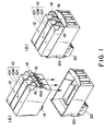
- Figure 1 is a schematic perspective view of an ink container compatible with the liquid filling method in an embodiment of the present invention, (A) and (B) presenting the ink container before and after the installation of the ink container, respectively.
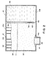
- Figure 2 is a vertical section of an ink container compatible with the liquid filling method in accordance with the present invention.
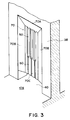
- Figure 3 is a perspective view of the essential portion of the ink container depicted in Figure 2.
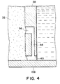
- Figure 4 is a section of the essential portion of the configuration of an ink container compatible with the liquid filling method in another embodiment of the present invention.
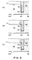
- Figure 5 is a schematic section of an ink container compatible with the ink liquid filling method in another embodiment of the present invention.
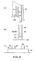
- Figure 6 are schematic perspective views of the partition wall of an ink container compatible with the liquid filling method in another embodiment of the present invention, a schematic section of the same, and a front view of the same, respectively.
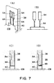
- Figure 7 are schematic perspective views of the partition wall of an ink container compatible with the liquid filling method in another embodiment of the present invention, a schematic section of the same, and a front view of the same, and a schematic section of the partition wall of an ink container compatible with the liquid filling method in another embodiment of the present invention, respectively.
- Figure 8 is a section of an ink container compatible with the liquid filling method in another embodiment of the present invention, and depicts the capillary force Hs of the absorbent material.
- Figure 9 is a section of an ink container compatible with the liquid filling method in another embodiment of the present invention, and depicts the head difference Hp between the capillary force generating portion, and the gas-liquid interface LL within the absorbent member, and the pressure loss ⁇ h of the absorbent member, in a liquid container in which gas-liquid exchange is occurring.
- Figure 10 is a section of an ink container compatible with the liquid filling method in another embodiment of the present invention, and depicts the head difference Hp between the capillary force generating portion, and the gas-liquid interface LL within the absorbent member, and the pressure loss ⁇ h of the absorbent member, in a liquid container in which gas-liquid exchange is occurring.
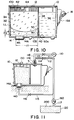
- Figure 11 is a sectional drawing which depicts a liquid filling apparatus and a liquid filling method in accordance with the present invention.
- Figure 12 is a sectional drawing which depicts a liquid filling apparatus, and a liquid filling method, in accordance with the present invention.
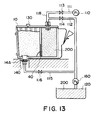
- Figure 13 is a sectional drawing which depicts a liquid filling apparatus, and a liquid filling method, in accordance with the present invention.
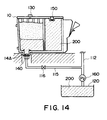
- Figure 14 is a sectional drawing which depicts a liquid filling apparatus, and a liquid filling method, in accordance with the present invention.
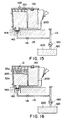
- Figure 15 is a sectional drawing which depicts a liquid filling apparatus, and a liquid filling method, in accordance with the present invention.
- Figure 16 is a sectional drawing which depicts a liquid filling apparatus, and a liquid filling method, in accordance with the present invention.
- Figure 17 is a sectional drawing which depicts a liquid filling apparatus, and a liquid filling method, in accordance with the present invention.
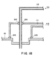
- Figure 18 is a schematic section of the essential portion of the liquid filling apparatus compatible with the liquid filling method in another embodiment of the present invention.
- Figure 1 is a schematic perspective view of an ink container compatible with the liquid filling method in accordance with the present invention, and an ink container holder in which the ink container is removably installable.
- Figure 1, (A, B) present their states before and after the installation of the container into the holder.
- An ink container 10 as a container for liquid to be ejected is approximately in the form of a parallelepiped.
- the top wall 10U of the container 10 is provided with an air vent, that is, a hole that leads to the internal space of the container 10.
- the ink container 10 is also provided with an ink delivery port 14, which is in the form of a cylinder.
- the ink delivery port 14 projects from the bottom wall 10B of the ink container 10, and has an ink delivery opening, that is, an opening through which the liquid is delivered outward when the ink container 10 is in use.
- the air vent 12 is kept sealed with a sheet of film or the like, and the cylindrical ink delivery port 14 is kept sealed with a cap as an ink delivery opening sealing member.
- a referential figure 16 designates a flexible lever, which is integrally formed with the ink container 10. It has a latching projection, which projects from the center portion of the lever.
- a referential figure 20 designates an ink container holder into which the ink container 10 is installed. It is integrally formed with a head.
- the ink container holder 20 holds, for example, an ink container 10C for cyan C ink, an ink container 10M for magenta M ink, and an ink container 10Y for yellow Y ink.
- the bottom portion of the ink container holder 20 is provided with a color ink jet head 22, which is integral with the holder 20.
- the color ink jet head 22 has a plurality of ejection outlets, which face downward (hereinafter, the head surface at which these ejection outlets open will be referred to as an ejection outlet opening surface).
- the ink container 10 is inserted into the ink container holder 20 integral with the color ink jet head 22, while being held as depicted in Figure 1, (A), so that the cylindrical ink delivery port 14 engages with the unillustrated ink receiving portion of the color ink jet head 22, and the cylindrical ink receiving port of the color ink jet head 22 enters the cylindrical ink delivery port 14. Then, the latching projection 16A of the lever 16 engages with an unillustrated projection located at a predetermined point of the ink container holder 20 integral with the head 22. Consequently, the ink container 10 is correctly held by the ink container holder 20 as depicted in Figure 1, (B).
- the ink container holder 20 After the ink container 10 is installed into the ink container holder 20 integral with the head 22, the ink container holder 20 is mounted onto the carriage of an unillustrated ink jet type recording apparatus, to be prepared for printing. As the ink container holder 20 which is holding the ink container 10 is mounted onto the carriage, a predetermined amount of head difference H is created between the bottom portion of the ink container 10 and the ejection outlet opening surface of the ink ejecting head.
- the internal space of the ink container 10 in this embodiment comprises two chambers separated by a partition wall 38; a negative pressure producing member chamber 34 (first chamber), and a liquid chamber 36 (second chamber).
- the negative pressure producing member chamber 34 holds an absorbent member 32 as a negative pressure producing member.
- the top wall of the negative pressure producing member chamber 34 has an air vent 12, through which the internal space of the negative pressure producing member chamber 34 is connected to the atmosphere, and the bottom wall of the negative pressure producing member chamber 34 has an ink delivery opening.
- the ink chamber 36 is virtually sealed, and holds liquid ink alone.
- the first chamber 34 and the second chamber 36 are connected to each other only through a communication port 40 cut through the bottom portion of the partition wall 38.
- the inward surface of the top wall 10U of the first chamber 34 is provided with a plurality of ribs 42, which are integrally formed with the wall 10U, and project straight inward.
- the absorbent member 32 is formed of thermal compression urethane foam, and is held compressed in the first chamber to produce a predetermined amount of capillary force as will be described later.
- the absolute value of the pore density of the absorbent member 32 for producing the predetermined amount of capillary force is varied depending on the type of the ink to be used, the measurement of the ink container 10, the vertical position (head difference H) of the ejection outlet opening surface of the ink jet head 22, and the like.
- the density needs to be at least approximately 50 pores per inch, because the absorbent member 32 is required to produce a capillary force greater than the capillary force produced by the capillary force producing groove, or a path, as a capillary force producing portion, which will be described later.
- a contact member 46 in the form of a disc or a circular column is disposed in the cylindrical ink delivery port 14 in the cylindrical ink delivery port 14.
- the contact member 46 is formed of propylene felt, and is not easily deformable by external force.
- the contact member 46 is inserted into the cylindrical ink delivery port 14 in such a manner that when the ink container 10 has not been inserted into the ink container holder 20, the absorbent member 32 remains locally compressed by the contact member 46 as shown in Figure 2.
- the outer edge of the cylindrical ink delivery port 14 is provided with a flange, which comes in contact with the contact member 46 as the contact member 46 is inserted into the cylindrical ink delivery port 14.
- the depth of the depression which the contact member 46 makes in the absorbent member 32 after the cylindrical ink receiving port of the aforementioned color ink jet head 22 is inserted into the cylindrical ink delivery port 14 is in a range of 1.03 - 3.0 mm, whereas the depth of the depression which the contact member 46 makes in the absorbent member 32 when the cylindrical ink receiving port of the head 22 is out of the cylindrical ink delivery port 14 is in range of 0.5 - 2.0 mm. This prevents ink from dripping after the ink container 10 is removed from the head 22, and also assures that ink desirably flows when the ink container 10 is in use.
- the contact member 46 Since the contact member 46 is disposed adjacent to the ink delivery portion, being pressed into the absorbent member 32, the portion of the absorbent member 32 which is in contact with the contact member 46 deforms. Therefore, if the ink delivery opening 14A is extremely close to a communication port 40, that is, a port through which gas-liquid exchange occurs, the deformation of the absorbent member 32 affects the gas-liquid exchange port, which causes the amount of ink filled into each container during the manufacturing process to be nonuniform. In the worst case, a proper amount of negative pressure may not be produced, and as a result, ink may drip from the ink delivery opening 14A.
- the distance between the communication port 40 and the ink delivery opening 14A is desired to be in a range of 10 - 50 mm.
- the relationship between the negative pressure producing member holding chamber 34 and the liquid holding chamber 36 will be described.
- the ink container 10 When the ink container 10 is in use, that is, when there is air in the top portion of the liquid holding chamber 36, the air expands as it is exposed to ambient temperature or pressure change. As a result, ink is sometimes forced out into the negative pressure producing holding chamber 34. This ink is absorbed by the absorbent member 32 in the negative pressure producing holding chamber 34.
- the volume of the absorbent member 32 should be set in consideration of every predictable condition under which the ink container 10 may be used; in other words, the absorbent member 32 should be rendered large enough to enable the absorbent member 32 to satisfactorily absorb even the largest amount of the ink which is possible to be formed out of the ink holding chamber 36 by the ambient temperature or pressure change.
- the actual liquid absorbing ability of the absorbent member 32 is not determined simply by the volume of the absorbent member 32, because the ink, which is forced out of the ink holding chamber 36, must be absorbed upward by the absorbent member 32 against gravity. Therefore, the ink may leak from the ink delivery opening even when the volume of the absorbent member 32 is large enough.
- the height of the absorbent member 32 is great (for example, it may be greater than 40 mm), and therefore, the ink forced out of the ink holding chamber 36 must be absorbed higher, that is, the ink level (gas-liquid interface) within the absorbent member 32 must be raised to a higher level.
- the speed at which the absorbent member 32 absorbs the ink may not be fast enough to deal with the amount of the ink being forced out of the ink holding chamber 36.
- This problem which is related to the speed at which the liquid level in the absorbent member 32 is raised, can be solved by changing the configuration of the absorbent member 32; it is desirable that size of the bottom wall of the negative pressure producing holding chamber 34 is increased.
- the volume of the negative pressure producing member holding chamber 34 also increases, which in turn reduces the volume of the ink holding chamber 36, because the overall volume available for the ink container 10 is limited. As a result, the amount of ink holdable in the ink container 10 is reduced.
- the ink absorbing speed of the absorbent member 32 is also affected by the surface tension of the ink. Therefore, when optimizing the ratio in volume between the negative pressure producing member holding chamber 34 and the ink holding chamber 36, the surface tension of the liquid to be held must be taken into consideration. For example, when an attempt was made to optimize the volume ratio between the negative pressure producing member holding chamber 34 and the ink holding chamber 36 while varying the surface tension ⁇ of the liquid to be held in a range of 30 - 50 dyn/cm, and also assuming that the normal temperature at which the ink container 10 is used was in a range of 5 - 35 deg., the optimum ratio fell in an approximate range of 1:1 - 5:3.
- the size of the air buffer chamber 44 in the negative pressure producing member holding chamber 34 it is desired to be rendered as small as possible from the standpoint of volumetric efficiency. However, it is necessary to assure that the air buffer chamber 44 has a large enough volume to prevent ink from spewing out of the air vent 12 when ink suddenly flows into the negative pressure producing member holding chamber 34. For this reason, it is desirable that the volume of the air buffer chamber 44 is set at approximately 1/5 - 1/8 of the volume of the negative pressure producing member holding chamber 34.
- the bottom portion of the negative pressure producing material holding chamber side of the partition wall 38 is provided with two parallel paths (grooves) 61 which constitute the capillary force generating portion of the atmospheric air introduction path.
- the grooves 61 extend along the lateral surface of the absorbent member 32 as the negative pressure producing material, and their bottom ends are connected to the communication port 40.
- the grooves 61 which constitute the capillary force generating portion, are thought to form such capillary tubes that generate capillary force between the surfaces of the grooves 61 cut in the partition wall 38 and the lateral surface of the absorbent member 32.
- the bottom portion of the negative pressure producing material holding chamber side of the partition wall 38 is provided with two parallel first parts (grooves) 54 as the atmospheric air introduction paths, and two parallel second paths (grooves) 55.
- the grooves 54 extend along the lateral surface of the absorbent member 32 as the negative pressure producing material, and their bottom ends are connected one for one to the top ends of the grooves 64, which also extend along the lateral surface of the absorbent member 32, and the bottom ends of which are connected to the communication port 40.
- These grooves 54 and 64, and the lateral surface of the absorbent member 32, form the atmospheric air introduction paths.
- a portion of the path 64 constitutes the capillary force generating portion.
- the bottom end portions of the second paths 64 which constitute the capillary force generating portion, may be connected, one for one, to parallel grooves 65 cut in the top surface of the communication port 40 in the longitudinal direction of the communication port 40.
- the partition wall 38 is provided with the first grooves 54 which are larger than the second grooves 64, and therefore, it is assured that a sufficient amount of the atmospheric air is introduced, reducing thereby the force that impedes the initiation of gas-liquid exchange.
- the second paths 64 are also thought to form such capillary tubes that generate capillary force between the surfaces of the grooves 61 cut in the partition wall 38 and the lateral surface of the absorbent member 32.
- the bottom edge of the second grooves 64 are tapered to make it easier for air to pass.
- the bottom portion of the negative pressure producing material chamber side of the partition wall 38 is provided with three pairs of a first groove 50 and a second groove 60, as shown in enlargement in Figure 3.
- the groove 50 extends along the lateral surface of the absorbent member 32 as the negative pressure producing material, and constitutes a part of the atmospheric air introduction path, together with the lateral surface of the absorbent member 32, and the groove 60 also extends along the lateral surface of the absorbent member 32, and constitutes another portion of the atmospheric air introduction path.
- the bottom end of the groove 50 is connected to the top end of the groove 60, and the bottom end of the groove 60 is connected to the communication port 40.
- the first grooves 50 and the second grooves 60 which constitute a capillary force generating portion, are cut in the bottom surface of a recess 70 of the partition wall 38.
- the recess 70 is cut in the negative pressure producing material chamber facing surface of the bottom end portion of the partition wall 38, being centered in terms of the width direction of the partition wall 38, and has three lateral surfaces 70A, 70B, and 70B, which are gently slanted relative to the surface of the partition wall 38 toward the center of the recess 70, and a bottom surface 70C, which is parallel to the surface of the partition wall 38.
- the width of the communication port 40 is rendered substantially equal to the width of this recess 70.
- the absorbent member 32 placed in the negative pressure producing member holding member 34 is pressed against five surfaces: the surface of the partition wall 38, the three lateral surfaces 70A, 70B, and 70B of the recess 70, and the bottom surface 70C of the recess 70.
- three capillary tubes which generate capillary force are formed by the three grooves 60 in the partition wall 38 and the lateral wall of the absorbent member 32.
- the atmospheric air introduction paths are formed by cutting the first and second grooves in the surface of the partition wall 38.
- the atmospheric air introduction path may be directly cut through the partition wall 38 as shown in Figure 4.
- an atmospheric air introduction path 56 as the first path, the opening side of which makes contact with the absorbent member 32 as the negative pressure producing material, and a capillary force generating path 66, as the second path, the internal end of which is connected to the internal end of the path 56, and the opening side, at the bottom end, of which is connected to the communication port 40 may be formed in the bottom portion of the partition wall 38.
- the capillary force generating path 66 is enabled to generate capillary force without being affected by the absorbent member 32, because it is not formed by covering the portions of the groove with the absorbent member 32 as it is in the cases of the preceding embodiments.
- Figure 8 depicts a state of the ink container 10, in which the liquid chamber 36 is being filled with ink; ink has been absorbed upward into the absorbent member 32 by the capillary force of the absorbent member 32, and the gas-liquid interface LL has risen to the level indicated in the drawing.
- the capillary force Hs of the absorbent member 32 that is, the capillary force of the absorbent member 32 expressed in terms of length by dividing the capillary force of the absorbent member by the product of the ink density ⁇ and the gravitational acceleration g, is measured as the vertical distance between the position of the gas-liquid interface LL before the beginning of gas-liquid exchange, and the position of the head of the liquid in a liquid tube extending from the gas-liquid interface LL.
- Figure 9 shows a state of the ink container 10, in which gas-liquid exchange has begun as ink consumption has started.
- Hp stands for the vertical distance between the gas-liquid interface LL within the absorbent member 32 as the negative pressure producing member, and the capillary force generating portion 60a within the second path 60 which comprises the capillary force generating portion 60a.
- a piece of thermal compression absorbent material is used as the absorbent member 32; the absorbent member 32 is thermally compressed in advance, and then, is inserted into the negative pressure producing member holding chamber 34.
- the absorbent member 32 becomes substantially uniform in terms of compression ratio. Therefore, the gas-liquid interface LL in the absorbent member 32 becomes substantially level, except for the edge portions at which it slightly rises.
- Figure 10 also shows a state of the ink container 10, in which gas-liquid exchange has begun as ink consumption has started.
- a piece of absorbent material which has not been compressed in advance is used as the absorbent member 32.
- a piece of absorbent material, the volume of which is substantially larger than the volume of the negative pressure producing member holding chamber 34 is compressed into the chamber 34, being reduced in volume by the compression, by 4 - 4.5 times.
- the absorbent member 32 is liable to become nonuniform in terms of compression ratio. Therefore, the gas-liquid interface LL in the absorbent member 34 becomes concave, with the edge portions rising much higher than the edge portions in Figure 9.
- Hp is the vertical distance between the lowest point of the gas-liquid interface LL and the capillary force generating portion 60a.
- ink is ejected from the ink jet head 22, which generates such force that works in the direction to such ink out of the ink container 10.
- the ink in the piece of negative pressure producing material that is, the absorbent member 32, in the negative pressure producing member holding chamber 34
- the top surface (gas-liquid interface) of the ink in the material descends (LL in Figure 2).
- the magnitude of the negative pressure generated at this time is determined by the capillary force, at the gas-liquid interface LL, of the negative pressure producing material, and the height of the gas-liquid interface LL from the ejection outlet opening surface.
- the gas-liquid interface LL first descends to the top end of the first path 50 of the atmospheric air introduction path, allowing the pressure in the second path 60 to increase. Then, as the pressure of the bottom portion of the liquid holding chamber 36 becomes lower than that of the second path 60, the atmospheric air is supplied into the liquid holding chamber 36 through the first and second paths 50 and 60. As a result, the pressure within the liquid holding chamber 36 increases by the amount equivalent to the amount of the introduced atmospheric air. Consequently, ink is supplied from the liquid holding chamber 36 into the absorbent member 32 through the communication port 40 to eliminate the difference between the increased pressure of the liquid holding chamber 36 and the pressure within the absorbent member 32 as the negative pressure producing member. In other words, gas is exchanged with liquid. As the gas-liquid exchange continues, the pressure in the bottom portion of the ink container increases by the amount equivalent to the amount of the ink supplied into the absorbent member 32, and eventually, the atmospheric air is prevented from being supplied into the liquid holding chamber 36.
- the ink in the liquid holding chamber 36 is supplied into the negative pressure producing member holding chamber 34 because the aforementioned gas-liquid exchange continuously occurs.
- the magnitude of the negative pressure produced in the liquid holding chamber 36 is determined by the capillary force generated in the second path 60.
- the magnitude of the negative pressure produced in the liquid holding chamber 36 while the ink is consumed can be controlled by selecting the measurement of the second path 60.
- the negative pressure producing member (absorbent member) 32 held in the negative pressure producing member holding chamber 34 has a large number of capillary tubes, and the meniscus force of these tubes generate negative pressure.
- the absorbent member 32 as the negative pressure producing member is soaked with a sufficient amount of ink, and therefore, it is assumed that the position of the head of the liquid in each theoretical capillary tube is sufficiently high.
- the magnitude of the negative pressure generated in the ink container 10 is determined by the capillary force of the theoretical capillary tubes in the negative pressure producing member 32, and the pressure head at the ejection outlet opening surface of the ink jet head 22 is determined by the pressure head difference between the gas-liquid interface LL and the ejection outlet opening surface.
- the gas-liquid interface LL descends farther to the position shown in Figure 5, (B).
- the top end of the first path 50 of the atmospheric air introduction path is slightly above the gas-liquid interface LL, allowing the atmospheric air to enter the first path 50.
- the ink container 10 is structured so that the capillary force generated in the second path 60 as the capillary force generating portion is rendered smaller than the capillary force generated by the theoretical capillary tubes of the absorbent member 32, the meniscus in the second path 60 is destroyed by the further consumption of ink.
- the atmospheric air X is introduced into the liquid holding chamber 36 through the second path 60 and the communication port 40, as shown in Figure 5, (C). During this period, the gas-liquid interface LL does not descend farther.
- the pressure in the liquid holding chamber 36 becomes higher than the pressure at the bottom of the negative pressure producing member holding chamber 34, and therefore, in order to eliminate the pressure difference, ink is supplied from the liquid holding chamber 36 to the negative pressure producing member holding chamber 34 by the amount equivalent to the amount of the pressure difference between the two chambers. Then, the pressure in the negative pressure producing member 32 becomes higher than the negative pressure produced by the second path 60, and therefore, ink flows into the second path 60, forming a meniscus. As a result, the introduction of the atmospheric air into the liquid holding chamber 36 is stopped.
- the meniscus in the second path 60 is destroyed again, without descent of the gas-liquid interface LL, and the atmospheric air is introduced into the liquid holding chamber 36, as described above.
- the destruction and regeneration of the meniscus in the second path 60 is repeated throughout the ink consumption, keeping substantially constant the negative pressure generated in the ink container 10, without the descent of the gas-liquid interface LL, that is, with the top end of the atmospheric air introduction path remaining in contact with the atmospheric air.
- the magnitude of this negative pressure is determined by the magnitude of the force necessary for the atmospheric air to destroy the meniscus in the second path 60; in other words, it is determined by the measurements of the second path 60 and the properties (surface tension, angle of contact, and density) of the ink being used.
- the magnitude of the capillary force generated in the second path 60 as the capillary force generating portion is set to a value between the highest and lowest values of the magnitude of the capillary force which tends to vary depending on the color and the type of the ink or the like processing liquid being held in the liquid chamber, the same ink container structure can be used for all types of ink or the like to be ejected, without change.
- the pressure at the ejection outlet opening surface of the ink jet head 22 is determined by the interaction among the capillary force generated in the second path 60, the pressure loss in the absorbent member 32, the difference in height between the bottom portion of the ink container and the ejection outlet opening surface, and the like.
- the negative pressure generated in the ink container 10 must be kept substantially constant. Further, after the ink container 10 has been inserted in the ink container holder 20 integral with the liquid ejection head, and the ink container holder 20 has been mounted on the carriage of an unillustrated ink jet type recording apparatus, that is, when the ink container 10 is on standby for printing, a predetermined pressure head difference has been established between the capillary force generating portion at the bottom of the ink container 10, and the ejection outlet opening surface. In this state, in order to prevent ink from leaking through the ejection outlet of the liquid ejecting head, the ink pressure at the ejection outlet opening surface in the ejection outlet must always remain below the atmospheric pressure.
- the vertical position of the gas-liquid interface LL must be kept steady; in other words, the vertical position of the meniscus at the gas-liquid interface LL within the absorbent member 32 must be kept steady in spite of the pressure loss which occurs as ink flows through absorbent member 32 while ink is consumed.
- the capillary force generated by the capillary force generating portion must satisfy the following formula: H ⁇ h ⁇ Hs - Hp - ⁇ h
- a symbol H stands for the pressure head difference between the capillary force generating portion and the ejection outlet opening surface of a liquid ejection type head
- a symbol Hp stands for the pressure head difference between the gas-liquid interface within the negative pressure producing member and the capillary force generating portion.
- L stands for the peripheral length (cm) of the tube; S, the cross sectional area of the tube (cm 2 ); ⁇ , the surface tension of ink (dyn/cm); ⁇ , , angle of contact; ⁇ , the density (g/cm 3 ) and g stands for gravitational acceleration (980 cm/s 2 ).
- the measurements of the capillary force generating portion are required to satisfy the following formula obtained by substituting Formula (1) into Formula (2). 1/cos ⁇ x ⁇ g/ ⁇ x H ⁇ L/S ⁇ 1/cos ⁇ x ⁇ g/ ⁇ x (Hs-Hp- ⁇ h)
- L stands for the peripheral length (cm) of the capillary force generating portion
- S the cross sectional area of the capillary force generating portion (cm 2 )
- ⁇ the density ink (g/cm 3 );
- g gravitational acceleration (980 cm/s 2 )
- ⁇ the surface tension of ink (dyn/cm);
- ⁇ stands for angle of contact.
- the ink pressure at the ejection outlet opening surface in the ejection outlet is desired to be rendered smaller by approximately -10 mm H 2 O than the atmospheric pressure, in view of the necessary for a safety margin.
- the capillary force h expressed in terms of length is desired to satisfy the following formula: H + hm ⁇ h ⁇ Hs - Hp - ⁇ h.
- Formula (3) can be rearranged into: 1/cos ⁇ x ⁇ g/ ⁇ x (H+hm) ⁇ L/S ⁇ 1/cos ⁇ x ⁇ g/ ⁇ x (Hs-Hp- ⁇ h)
- the width is in a range of 0.20 - 0.40 mm, and the depth is in the range of 0.20 - 0.40 mm. From the standpoint of keeping as small as possible the amount of invasion into the absorbent member 32 by the grooves, the width is desired to be less than the depth.
- the cross sectional area of the first path 50 is that it is larger than the cross sectional area of the second path 60.
- the length of the second path 60 it should extend upward 2 - 10 mm from the top edge of the communication port 40. If it is too short, the contact by the absorbent member 32 does not stabilize, whereas if it is too long, the second path 60 becomes sensitive to the invasion by the absorbent member 32. Therefore, the length of the second path 60 is desired to be approximately 4 mm.
- the vertical position of the top end of the first path 50 regulates the vertical position of the gas-liquid interface in the absorbent member 32, and therefore, the top end of the first path 50 must be positioned so that ink delivery is not interrupted, and the buffing function of the absorbent member 32 is not hindered.
- the vertical position of the top end of the first path 50 is approximately 10 - 30 mm from the top edge of the communication port 40.
- Figures 11 - 16 are schematic drawings which depict the processes, in the first embodiment, for filling liquid into a liquid container.
- a liquid container 10 which comprises a partition wall, which has an atmospheric air introduction path for introducing the atmospheric air from the negative pressure producing member chamber into a liquid chamber.
- the portion of the atmospheric introduction path constitutes a capillary force generating portion.
- the liquid container 10 in this embodiment has an ink injection port 5, which is located in the top portion of the second chamber, and through which liquid is injected.
- the "top surface portion” means the surface which faces the bottom surface of the liquid container in this embodiment.
- the liquid container is immovably placed in an ink injecting apparatus, with the communication port facing downward as shown in Figure 11. Then, the ink delivery opening 14A and the air vent 12 are sealed, and the internal pressure of the ink chamber is reduced by evacuating the air within the liquid chamber. During this process, the angle of the ink container is the same as the angle which the ink container must assume to deliver ink (liquid) to the liquid ejecting head.
- the ink ejecting apparatus in this embodiment comprises an ink reservoir 120 for holding ink 200 to be filed, and a vacuum pump 110 for reducing the internal pressure of the liquid container. It also comprises: tubes or pipes for connecting the reservoir 120 and the vacuum pump 200 to an ink container; valves placed midway along the passages; members for sealing an ink container; a locking device for firmly holding an ink container at the same angle as the angle at which the ink container is held when in use (communication port facing downward), and the like.
- the ink reservoir 120 is open to the atmosphere, and an ink transfer tube 117 is inserted in the reservoir 120.
- the ink transfer tube 117 branches into two ink injection tubes 112 and 115, and is equipped with a pump 60 for transferring ink, so that ink can be transferred from the ink reservoir 120 to the ink ejection tubes 112 and 115 at a predetermined amount per unit of time.
- Both ink injection tubes 112 and 115 are equipped with valves 114 and 116, respectively, at their middle sections, and their ink container side ends are fitted with coupling members 119 and 140, respectively.
- Ink can be flowed into the ink injecting tube 112 by opening the valve 114 while keeping the value 116 closed, and into the ink injecting tube 115 by opening the valve 116 while keeping the valve 114 closed.
- the amount of ink flowed into each ink injection tube can be varied by controlling the revolution of the motor for the pump.
- the vacuum pump 110 is connected to a vacuum tube 111 for reducing the internal pressure of a liquid container.
- the ink container side of the vacuum tube 111 turns into a tube 118, the middle section of which is connected to the ink injection tube 112, and the ink container side of which is fitted with a coupling member (sealing member) 119.
- the vacuum tube 111 is equipped with a valve 113, which is located midway between the point where the vacuum tube turns into a tube 118, and the vacuum pump 110.
- an ink container is placed in a sealed state by sealing the air vent 12 with a sealing member 130, coupling the ink delivery port 14 with the coupling member 140, closing the valve 116, and coupling the ink injection port 5 with the coupling member 119.
- the internal pressure of the sealed ink container is reduced by operating the vacuum pump 110 after closing the valve 114 and opening the valve 113.
- the internal pressure of an ink container is reduced to approximately 0.01 - 0.05 in absolute pressure.
- ink is injected into the second chamber through the ink injection port 5, as shown in Figures 12 and 13.
- ink can be injected into the second chamber through the ink injection port 5 at a predetermined high ink filling speed by closing the valve 113, stopping the vacuum pump 110, operating the pump 160, and opening the valve 114.
- Ink is first injected into the second chamber. Then, ink is also injected into the first chamber through the communication port 40 while ink is injected into the second chamber, because during this ink filling process, the internal pressure of the ink container is reduced throughout the entire internal space of the ink container.
- the speed at which liquid is filled into the second chamber is first, the amount of the ink filled into the first chamber by the time the second chamber is completely filled with liquid is very small.
- the ink having filled into the negative pressure producing member permeates mainly through the surface portion of the negative pressure producing member, forming a gas-liquid interface.
- only limited regions of the negative pressure producing member, that is, the adjacencies of the communication port, and the surface portions, are filled with ink. Therefore, it is assured that the second chamber is filled completely, that is, without leaving any of its regions unfilled with ink, before the internal pressure-reduced condition of the first chamber significantly changes from the condition at the end of the internal pressure reducing process depicted in Figure 11.
- ink is filled into the first chamber by an amount large enough to fill the negative pressure producing member, up to the adjacencies of the top end of the atmospheric air introduction path, the ink having been filled into the first chamber permeates into the region with low flow resistance in the negative pressure producing member, leaving the region with high flow resistance in the negative pressure producing member unfilled with ink.
- the inventors of the present invention paid attention to the relationship between the speed at which liquid is filled, and the speed at which the negative pressure producing member absorbs ink upward, and set up the ink filling speed at such a speed the ink is filled through the ink injection port, substantially faster than the speed at which ink permeates substantially deep into the negative pressure producing member.
- the ink injecting speed has only to be such a speed that exceeds the speed at which the capillary force of the negative pressure producing member absorbs ink upward against the flow resistance.
- the tests which were conducted by the inventors of the present invention confirmed that when the negative pressure producing member formed of compressed polyurethane foam with an average pore size of 90 - 200 pore/inch was used; surface tension of ink ⁇ was 30 - 50 dyn/cm; ink viscosity was approximately 2 cps; the length h1 and cross sectional area of the communication port illustration in Figure 12 were 2 mm and 11 - 15 mm 2 , respectively; and the bottom surface area and height of the second chamber were 4.5 - 10 mm 2 and 51.5 mm, respectively, the height to which ink was absorbed in the region adjacent to the atmospheric air introduction path, in the negative pressure producing member, could be kept below the height H of the atmospheric air introduction path as long as the aforementioned ink injection speed was kept at a speed no less than 15 cc/sec and
- the reason for setting an upper limit to the ink filling speed is that if the injection speed is excessive, it is possible that the negative pressure producing member held in the negative pressure producing member chamber may be shifted within the chamber.
- the ink injection port 5 is sealed, and then, ink is filled into the first chamber through the ink delivery opening 14A. More specifically, in this embodiment, first, the valve 114 is closed, and the coupling portion is removed from the ink injection port. Then, the ink injection port is sealed with a ball 150 formed of SUS or the same material as the material for the liquid container. Therefore, the ink delivery speed of the pump 160 is adjusted. Finally, the valve 116 is opened to start filling ink into the first chamber through the ink delivery opening 14A.
- ink into the first chamber through the ink delivery opening 14A assures, in conjunction with the ink 200 filled into the negative pressure producing member in the first chamber while ink is filled through the second chamber side as shown in Figures 12 and 13, that the ink delivery route is desirably filled with ink, and also that the negative pressure producing member is virtually evenly filled with ink, that is, without leaving any region in the negative pressure producing member unwetted with ink, as shown in Figures 14 and 15.
- the ink filling speed is slightly reduced, compared to the aforementioned speed at which ink is injected into the second chamber, by changing the ink delivery speed of the pump 160, because if the ink filling speed is too fast, ink is liable to be filled through easily passable regions, for example, the gap between the negative pressure producing member and the wall of the first chamber which is holding the negative pressure producing member. According to this embodiment, a speed of approximately 15 cc/sec was desirable.
- the ink delivery opening is sealed as shown in Figure 16, and then, the air vent is opened to introduce air into the first chamber from outside.
- the state of the liquid container in terms of internal pressure is restored from the pressure-reduced state to the normal pressure state. More specifically, in this embodiment, first, the valve 116 is closed, and then, the pump 160 is stopped. Thereafter, the sealing member 130 is removed from the air vent to allow the air to enter the first chamber.
- Restoring the internal pressure of the liquid container from the reduced state to the normal state by unsealing the air vent as in this embodiment can cause the so-called free ink, that is, the ink which oozes out of the negative pressure producing member while ink is filled into the negative pressure producing member, to be forced back into the negative pressure producing member to be held therein, if free ink happens to be present.
- a predetermined amount of liquid can be removed through the ink delivery opening 14A by operating the pump 160 in reverse, to turn a region 32a, adajcent to the buffer chamber, of the negative pressure producing member, into such a region that is not holding ink, and a region 32b, that is, the other region of the negative pressure producing member, into such a region that is holding ink in a desirable manner, so that the gas-liquid interface 220 becomes substantially horizontal as shown in Figure 16.
- This process is carried out as necessary, for example, when it must be assured that a region which is not holding ink is secured in the top portion of the negative pressure producing member, for example, the region adjacent to the buffer chamber.
- liquid filling method in accordance with the present invention reduce, by increasing the speed at which liquid is filled into the second chamber, the time necessary to inject liquid into a container, but also assures that ink is desirably filled into the second chamber. Therefore, it greatly improves productivity.
- liquid containers with a second chamber capacity of no less than 10 cc are preferable; it does not means that the present invention is not applicable to containers with a second chamber capacity of no more than 10 cc.
- the ingredients of the ink to be filled those inks which contain surfactant, for example, acetynol, by no more than 1 %, or those inks which do not contain any surfactant, are low in permeability into the negative pressure producing member, and are therefore difficult to fill into the negative pressure producing member at a high speed.
- the liquid filling method in accordance with the present invention makes it possible to fill even those inks into a liquid container at a high speed, by filling liquid into the liquid container after reducing the internal pressure of the liquid container.
- the internal space of a liquid container is opened to the atmospheric air after a liquid container is completely filled with ink.
- the internal space of a liquid container may be opened to the atmospheric air immediately before the negative pressure producing member chamber is completely filled with ink.
- opening the air vent immediately before the negative pressure producing member chamber is completely filled with ink can mitigate the effects of the sudden change which occurs to the state of the liquid container; for example, it can prevent air from being pulled into the second chamber by the sudden contraction of the certain regions of the internal space of the second chamber, which has not been filled with ink.
- Carrying out the above described process can also prevent the ink 201 from adhering to the walls of the air buffer chamber as shown in Figure 15, and therefore, can afford more latitude in designing the shape or structure of the air buffer chamber.
- process that characterizes this embodiment may be carried out in combination with the process of discharging a predetermined amount of liquid from the ink delivery opening, which was described in the first embodiment.
- ink is filled through the ink delivery opening of the first chamber after the completion of the ink filling into the second chamber.
- a small amount of ink may be filled through the ink delivery opening 14A of the first chamber before liquid is filled into the second chamber as shown in Figure 17.
- an arrangement is made to fill the small amount of ink present between the valve 116 of the ink transfer tube 115, and the coupling member 140, into a liquid container at the same time as the internal pressure of the liquid container begins to be reduced after the container is firmly held.
- Filling a minute amount of ink into the first chamber before filling liquid into the second chamber as described above can assure that the ink delivery route is desirably filled during the process of filling into the first chamber. It is desirable that the amount of the ink to be filled during this process is just enough to wet the bottom portion of the negative pressure producing member, that is, the portion adjacent to the ink delivery opening and the communication port.
- This process of filling a minute amount of ink into the first chamber may be carried out at the same time as, or after, the pressure reducing process.
- the choice of the liquid injecting apparatus compatible with the liquid filling method in accordance with the present invention described in the preceding embodiments is not limited to the liquid injecting apparatus described in the preceding embodiments.
- the structure depicted in Figure 18 may be used, in which the gaps between the vacuum tube 111 and the liquid container 10 are sealed with sealing members 215, and an ink injection tube 112 is put through a hole cut in the wall of the expanded portion of the vacuum tube 111, the gap between the edge of the hole and the vacuum tube 111 being sealed with sealing members 120.
- additional opening which is different from the ink injection opening, may be cut in the wall of the second chamber, so that one opening is connected to the vacuum tube, and the other is connected to the ink injecting tube.
- the last arrangement can prevent ink from detouring into the vacuum pump through the vacuum tube, and deteriorating the performance of the vacuum pump, during the pressure reduction.
- ink is referred to as the liquid to be filled.
- the present invention is also compatible with liquid other than ink, for example, processing liquid for improving image quality, as long as the liquid is such liquid that is ejectable from a liquid ejecting head to which a liquid container is connected.
- the liquid filling method in accordance with the present invention was described as a method for injecting liquid into a liquid container during one of the manufacturing processes for a liquid container.
- the liquid filling method in accordance with the present invention is also usable, with desirable results, for refilling a liquid container after or before the container is completely depleted of liquid.
- the liquid filling method in accordance with the present invention is such a liquid method that is usable for not only initially filling a liquid container, but also refilling a liquid container after a liquid container is put to use.
- the liquid filling method in accordance with the present invention not only can the time necessary for injecting liquid into a liquid container be reduced by increasing the speed at which liquid is filled into the second liquid chamber, but also assures that ink is accurately filled into the second chamber.
- the liquid filling method in accordance with the present invention is a liquid filling method with high injection accuracy and high productibity.
- liquid is filled into a liquid container after the pressure of the entire internal space of the liquid container is reduced, and therefore, even liquid such as ink which is slow in permeating a negative pressure producing member can be filled at a high speed.
- the liquid in the first chamber is discharged by a predetermined amount to create a region rid of liquid, in the negative pressure producing member, adjacent to the buffer chamber, after the first chamber is completely filled.
- This region rid of liquid possesses a proper degree of absorbency for cushioning the liquid container against ambience changes or the like.
- liquid is filled into the adjacencies of the communication port through the liquid delivery port of the first chamber, assuring that the portion of the negative pressure producing member, which becomes an ink delivery route while a liquid container is in use, is desirably filled with liquid. Therefore, even if container size is large, liquid is reliably delivered.
Description
- The present invention relates to a method for filling liquid into a liquid container, in particularly, a method for filling liquid into an ejection liquid container desirable as a container for holding liquid ink or processing liquid used in an ink jet recording apparatus.
- A liquid container or a liquid ejection head cartridge used in a liquid ejecting apparatus, in particular, an ink jet type recording apparatus, has two ports: an ink delivery port through which liquid (ink) is supplied to a recording means such as an ink jet head, and an air vent, through which the atmospheric air is introduced into the container by a volume equivalent to the amount of ink consumption.
- This type of ink container is required to be able to stably supply the recording means with ink, without interruption, during a recording period, and also to be able to reliably prevent ink from leaking regardless of ambient conditions, during a non-recording period.
- In order to satisfy the above requirements, the inventors of the present invention proposed a liquid container which had a virtually sealed space for holding liquid such as ink, and a negative pressure producing chamber. The negative pressure producing chamber was disposed next to the virtually sealed space, and had a negative pressure producing member. This container is disclosed Japanese Laid-Open Patent Application No. Hei 7-125232, U.S. Patent No. 5,509,140, Japanese Laid-Open Patent Application No. Hei 7-68778, and the like publications.
- As a representative invention of such a type, Japanese Laid-Open Patent Application No. Hei 7-125232 discloses an invention, according to which an ink delivery tube is laterally inserted into the liquid container to create such a pressure distribution pattern, in the negative pressure producing material within the container, that allows the ink within the sealed space to be methodically consumed as the liquid (ink) is replaced by gas (air).
- The specification of U.S. Patent No. 5,509,140 discloses an invention, as a representative invention, according to which an ink container is given an internal structure which enhances gas-liquid exchange so that a region with stable negative pressure can be established within the liquid container at an early stage of ink consumption, through gas-liquid exchange.
- Further, Japanese Laid-Open Patent Application No. Hei 7-68778 discloses an invention, according to which an ink container is structured so that ink is delivered through a part of the bottom wall, and the bottom wall is provided with a recessed portion as a temporary ink reservoir. This invention is in accordance with the above-described invention disclosed in the specification of U.S. Patent No. 5,509,140.
- Japanese Laid-Open Patent Application Hei 7-125232 discloses an ink container which comprises two chambers. One chamber is a negative pressure producing material holding chamber, which is provided with an air vent, and holds negative pressure producing material. The other chamber is a liquid holding chamber, which is connected to the negative pressure producing material holding chamber, and holds nothing but the ink. This ink is delivered to the negative pressure producing material through a minute passage only, which is disposed between the two chambers, away from the air vent. According to this invention, the ink container is stabilized in terms of negative pressure, so that ink delivery efficiency is improved.
- A method for filling an ink container (ink cartridge) with the above described structure is disclosed in Japanese Laid-Open Patent Application No. Hei 8-090785. According to this application, while ink is filled into an ink container, the ink container is held in a slanted position, and ink is filled into the container, carefully timing the opening or shutting of the ink delivery opening and the air vent. Another ink filling method is disclosed in Japanese Laid-Open Patent Application No. Hei 8-132636 (corresponding to EP-A-0 703 083), according to which ink is filled into an ink container by reducing the internal pressure of the ink container.
- The above described ink filling methods for filling an ink container with ink are quite rational from the standpoint of reliably filling ink into an ink container, or an ink jet cartridge comprising an ink container and a recording head, while preventing ink from leaking.
- However, as usage of ink jet type recording apparatuses has spread widely and rapidly in recent years, demands for faster printing, and prints with high quality have also increased. Faster printing, and high quality prints, require ink container exchange frequency to be reduced, and in order to reduce ink container exchange frequency, an ink container with a large capacity is desired. From the standpoint of size reduction of a recording apparatus, a large capacity ink container is desired to have such a structure that liquid is delivered to a recording head through a part of the bottom wall of the ink container.
- Further, such ink containers with a large ink capacity, and ink cartridges comprising such an ink container, are desired to e as inexpensive as possible in a consumer market. Therefore, a less expensive and more efficient method for filling ink into an ink container during ink container manufacturing has been sought after.
- Thus, the inventors of the present invention studied liquid containers, which comprised a liquid holding chamber, and a negative pressure producing chamber. The liquid holding chamber was virtually sealed, and exclusively held liquid, and the negative pressure producing chamber contained a piece of negative pressure producing material, or a negative pressure producing member. The inventors of the present invention also studied liquid filling methods, which were supposed to be capable of filling liquid into the above described liquid containers at a high speed even if the size of the negative pressure producing chamber, which contained the negative pressure producing material, was increased by extending the chamber in the direction parallel to the bottom wall, and at the same time, the overall space surrounded by the external walls of the liquid container was also increased.
- The studies revealed that if conventional liquid filling methods are used to fill liquid into the large capacity container which delivers liquid to a head from a part of the bottom wall of the liquid container, there sometimes will be problems in filling the liquid containers.
- For example, in the case of the ink filling method disclosed in Japanese Laid-Open Patent Application No. Hei 8-090785 (corresponding to EP-A-0 703 083), the timing with which the air vent and the ink delivery port are opened or closed, and the angle of an ink container, must be changed according to the amount of the ink having been filled into the container. Therefore, an ink filling apparatus in accordance with this ink filling method becomes too complicated, and also, it is possible that manufacturing related nonuniformity may increase due to variation in the time necessary to switch manufacturing steps.
- In the case of the ink filling method disclosed in Japanese Laid-Open Patent Application No. Hei 8-132636, the internal pressure of an ink container is first reduced, and then, ink is filled from the porous material side. In other words, in the case of this liquid filling method, ink is filled through a large piece of porous material. Therefore, ink sometimes suddenly enters an ink chamber before the porous material is completely filled with ink. This creates a problem in that a substantial portion of the ink chamber may not be filled with ink. If a substantial portion of an ink chamber is not filled with ink, the ink container becomes very sensitive to the pressure of the ambience in which the ink container, having been sealed for shipment, is unsealed to be used for the first time or the like occasion; in other words, ink may leak, or air may enter the ink container through the ink delivery opening for delivering ink outward, and consequently, the liquid may be prevented from being stably delivered.
- Further, in the case of the ink filling method disclosed in Japanese Laid-Open Patent Application No. Hei-8-230209 (corresponding to EP-A-0 719 646), as liquid is rapidly filled into a liquid container structured to be filled with liquid through a part of its bottom wall, the negative pressure producing member is nonuniformly filled with ink. This nonuniform ink distribution in the negative pressure producing material is caused because the liquid is filled into the negative pressure producing material chamber through a passage which connects the negative pressure producing material chamber and the liquid chamber. With ink being nonuniformly distributed in the negative pressure producing material, it is possible for air to be introduced into a recording head through the air vent before the liquid in the liquid chamber is consumed for recording. As a result, ink delivery is liable to be interrupted.
- An object of the present invention is to provide a highly productive ink filling method and a highly productive ink filling apparatus, which can assure that a liquid container structured to deliver liquid to a head through a part of its bottom wall is prevented from being nonuniformly filled with liquid, even if the container is large.
- Another object of the present invention is to provide a liquid filling method which is capable of making full use of the advantageous characteristics of the aforementioned ink container to stably deliver the liquid when the ink container is in use.
- According to an aspect of the present invention, there is provided method of supplying liquid into a liquid container, which includes a first chamber, provided with a liquid supply portion for supplying liquid out, to a liquid ejection head and an air vent for fluid communication with ambient air, for accommodating therein a negative pressure producing member; a second chamber forming a substantially sealed space except for a communication part with the first chamber, wherein the liquid supply portion is disposed at a bottom side; and a gas-liquid exchange promoting structure, provided in the first chamber, for introducing the ambient air into the second chamber to permit discharging of the liquid, the method comprising: a pressure reducing step of reducing a pressure of an entirety of the container, while the liquid container is hermetically sealed; first liquid supplying step of supplying the liquid into the second chamber, and completing the liquid supply before a portion adjacent to the gas-liquid exchange promoting structure of the negative pressure producing member in the first chamber is supplied with the liquid, in a reduced pressure state provided by the pressure reducing step, with the container taking the same orientation as when the liquid supplied to the liquid ejecting head; a second liquid supplying step of supplying the liquid into the first chamber through the liquid supply portion, after the first liquid supplying step into the second chamber; a releasing step of releasing the hermetically sealed state of the first chamber after the second liquid supplying step into the first chamber.
- According to anther aspect of the present invention, there is provided a method of supplying liquid into a liquid container, which includes a first chamber, provided with a liquid supply portion for supplying liquid out, to a liquid ejection head and an air vent for fluid communication with ambient air, for accommodating therein a negative pressure producing member; a second chamber forming a substantially sealed space except for a communication part with the first chamber, wherein the liquid supply portion is disposed at a bottom side; and a gas-liquid exchange promoting structure, provided in the first chamber, for introducing the ambient air into the second chamber to permit discharging of the liquid, the method comprising: a pressure reducing step of reducing a pressure of an entirety of the container, while the liquid container is hermetically sealed; first liquid supplying step of supplying the liquid into the second chamber, and completing the liquid supply before a portion adjacent to the gas-liquid exchange promoting structure of the negative pressure producing member in the first chamber is supplied with the liquid, in a reduced pressure state provided by the pressure reducing step, with the container taking the same orientation as when the liquid supplied to the liquid ejecting head; a second liquid supplying step of supplying the liquid into the first chamber through the liquid supply portion, after the first liquid supplying step into the second chamber; a liquid discharging step of discharging a predetermined quantity of the liquid from the first chamber through the liquid supply portion after the second liquid supplying step.
- The liquid filling method in accordance with the present invention means such a liquid filling method that can be used for not only filling a liquid container during a liquid container manufacturing step, but also desirably refilling an ink container after it is completely or partially depleted of the liquid. In other words, it is a liquid filling method usable for initially filling a liquid container, as well as refilling the liquid container after the liquid container is put to use.
- According to the aforementioned ink filling method based on the present invention, the second chamber can be rapidly and reliably filled with liquid. Further, the negative pressure producing member is evenly filled with liquid, without leaving any region of the negative pressure producing member unwetted, by filling liquid into the first chamber through the liquid delivery portion of the first chamber. In other words, the present invention can provide a highly productive precise liquid filling method.
- Further, after the first chamber is completely filled with liquid, the liquid in the first chamber is discharged by a predetermined amount from the liquid delivery port, to assure that a region, which has a desirable degree of absorbency for enabling the liquid container to properly react to changes in ambience or the like, is created adjacent to the air vent, in the negative pressure producing material.
- This liquid filling method can provide high precision and high efficiency in liquid filling, on its own. However, this liquid filling methods is desirable to be used in combination with the following processes, because such a combination can enhance the merits of this method.
- 1. To take a liquid container out of a sealed state just before the first chamber is completely filled with liquid. This process can prevent gas (air) from being rapidly introduced into the liquid chamber; gas (air) is prevented from unexpectedly entering the liquid chamber.
- 2. To fill liquid into the adjacencies of the communication port, through the liquid delivery port or the first chamber, before starting to fill the second chamber with liquid. This process assures that the portion of the negative pressure producing member, which becomes the ink flow route when a liquid container is use, is properly filled for stably delivering liquid even if the liquid container in use has the aforementioned structure and also is large.
-
- These processes are effective individually to enhance productivity, but they can further enhance the objects of the present invention when used in combination.
- The liquid ejecting method in accordance with the present invention is particularly suitable for liquid containers which have a second chamber with an internal volume of 10 cc or greater, although it is also compatible with liquid containers which have a second chamber with an internal volume of less than 10 cc.
- According to a further aspect of the present invention, there is provided an apparatus for supplying liquid into a liquid container, which includes a first chamber, provided with a liquid supply portion for supplying liquid out, to a liquid ejection head and an air vent for fluid communication with ambient air, for accommodating therein a negative pressure producing member; a second chamber forming a substantially sealed space except for a communication part with the first chamber, wherein the liquid supply portion is disposed at a bottom side; and a gas-liquid exchange promoting structure, provided in the first chamber, for introducing the ambient air into the second chamber to permit discharging of the liquid, the apparatus comprising: sealing means for sealing the liquid container; pressure reducing means for reducing a pressure of an entirety of the container, while the liquid container is hermetically sealed; first liquid supplying means for supplying the liquid into the second chamber, and completing the liquid supply before a portion adjacent to the gas-liquid exchange promoting structure of the negative pressure producing member in the first chamber is supplied with the liquid, in a reduced pressure state provided by the pressure reducing step, with the container taking the same orientation as when the liquid supplied to the liquid ejecting head; second liquid supplying means for supplying the liquid into the first chamber through the liquid supply portion, after the first liquid supplying step into the second chamber; releasing means for releasing the hermetically sealed state of the first chamber after the second liquid supplying step into the first chamber.
- According to this aspect of the present invention, it is possible to provide a liquid filling apparatus, with which the aforementioned liquid filling method can be desirably carried out.
- In this specification of the present invention, a "top portion" means the portion which directly faces the bottom wall of a liquid container. When the top portion is on the top, the communication port is at the bottom.
- An expression, "region which is located adjacent to the top portion of the first chamber, and is not filled with liquid (ink)" is used as a sentence that means not only an empty space (air buffer chamber), that is, a space without the negative pressure producing material, but also a region which is filled with the negative pressure producing material, but is not filled with liquid (ink).
- The expressions, "negative pressure producing material holding chamber" and "ink holding chamber", are applied to only such a chamber that meets requirements for holding or storing ink (liquid), whereas the expressions, "first chamber" and "second chamber", are more loosely used to refer to the chambers; not only are they applied to a chamber which meets the requirements for holding and storing ink (liquid), but also a chamber which is in a process of satisfying the requirements.
- The structure, in accordance with the present invention, for enhancing gas-liquid exchange includes any structure that can introduce the atmospheric air into a liquid chamber to allow the liquid in the virtually sealed liquid chamber to be supplied to a negative pressure producing material chamber, without substantially changing the negative pressure (correspondent to liquid level) produced by the negative pressure producing material; for example, the atmospheric air introduction path described in the specification of the present invention, an atmospheric air priority path formed by differentiating the pore size in a predetermined region of the negative pressure producing material from the pore size in the other region, an atmospheric air introduction path constituted of a piece of tube, or an atmospheric air introduction path constituted of the minute gap formed between the absorbent material and the wall.
- These and other objects, features and advantages of the present invention will become more apparent upon a consideration of the following description of the preferred embodiments of the present invention taken in conjunction with the accompanying drawings.
- Figure 1 is a schematic perspective view of an ink container compatible with the liquid filling method in an embodiment of the present invention, (A) and (B) presenting the ink container before and after the installation of the ink container, respectively.
- Figure 2 is a vertical section of an ink container compatible with the liquid filling method in accordance with the present invention.
- Figure 3 is a perspective view of the essential portion of the ink container depicted in Figure 2.
- Figure 4 is a section of the essential portion of the configuration of an ink container compatible with the liquid filling method in another embodiment of the present invention.
- Figure 5 is a schematic section of an ink container compatible with the ink liquid filling method in another embodiment of the present invention.
- Figure 6, (A, B and C), are schematic perspective views of the partition wall of an ink container compatible with the liquid filling method in another embodiment of the present invention, a schematic section of the same, and a front view of the same, respectively.
- Figure 7, (A, B, C and D), are schematic perspective views of the partition wall of an ink container compatible with the liquid filling method in another embodiment of the present invention, a schematic section of the same, and a front view of the same, and a schematic section of the partition wall of an ink container compatible with the liquid filling method in another embodiment of the present invention, respectively.
- Figure 8 is a section of an ink container compatible with the liquid filling method in another embodiment of the present invention, and depicts the capillary force Hs of the absorbent material.
- Figure 9 is a section of an ink container compatible with the liquid filling method in another embodiment of the present invention, and depicts the head difference Hp between the capillary force generating portion, and the gas-liquid interface LL within the absorbent member, and the pressure loss δ h of the absorbent member, in a liquid container in which gas-liquid exchange is occurring.
- Figure 10 is a section of an ink container compatible with the liquid filling method in another embodiment of the present invention, and depicts the head difference Hp between the capillary force generating portion, and the gas-liquid interface LL within the absorbent member, and the pressure loss δ h of the absorbent member, in a liquid container in which gas-liquid exchange is occurring.
- Figure 11 is a sectional drawing which depicts a liquid filling apparatus and a liquid filling method in accordance with the present invention.
- Figure 12 is a sectional drawing which depicts a liquid filling apparatus, and a liquid filling method, in accordance with the present invention.
- Figure 13 is a sectional drawing which depicts a liquid filling apparatus, and a liquid filling method, in accordance with the present invention.
- Figure 14 is a sectional drawing which depicts a liquid filling apparatus, and a liquid filling method, in accordance with the present invention.
- Figure 15 is a sectional drawing which depicts a liquid filling apparatus, and a liquid filling method, in accordance with the present invention.
- Figure 16 is a sectional drawing which depicts a liquid filling apparatus, and a liquid filling method, in accordance with the present invention.
- Figure 17 is a sectional drawing which depicts a liquid filling apparatus, and a liquid filling method, in accordance with the present invention.
- Figure 18 is a schematic section of the essential portion of the liquid filling apparatus compatible with the liquid filling method in another embodiment of the present invention.
- Hereinafter, the embodiments of the present invention will be described with reference to the drawings.
- First, referring to Figures 1 and 2, the configuration of a liquid container compatible with the liquid filling method in accordance with the present invention will be described.
- Figure 1 is a schematic perspective view of an ink container compatible with the liquid filling method in accordance with the present invention, and an ink container holder in which the ink container is removably installable. Figure 1, (A, B) present their states before and after the installation of the container into the holder.
- An
ink container 10 as a container for liquid to be ejected is approximately in the form of a parallelepiped. The top wall 10U of thecontainer 10 is provided with an air vent, that is, a hole that leads to the internal space of thecontainer 10. - The
ink container 10 is also provided with anink delivery port 14, which is in the form of a cylinder. Theink delivery port 14 projects from the bottom wall 10B of theink container 10, and has an ink delivery opening, that is, an opening through which the liquid is delivered outward when theink container 10 is in use. During shipment, theair vent 12 is kept sealed with a sheet of film or the like, and the cylindricalink delivery port 14 is kept sealed with a cap as an ink delivery opening sealing member. - A referential figure 16 designates a flexible lever, which is integrally formed with the
ink container 10. It has a latching projection, which projects from the center portion of the lever. - A referential figure 20 designates an ink container holder into which the
ink container 10 is installed. It is integrally formed with a head. In this embodiment, theink container holder 20 holds, for example, an ink container 10C for cyan C ink, an ink container 10M for magenta M ink, and an ink container 10Y for yellow Y ink. The bottom portion of theink container holder 20 is provided with a colorink jet head 22, which is integral with theholder 20. The colorink jet head 22 has a plurality of ejection outlets, which face downward (hereinafter, the head surface at which these ejection outlets open will be referred to as an ejection outlet opening surface). - The
ink container 10 is inserted into theink container holder 20 integral with the colorink jet head 22, while being held as depicted in Figure 1, (A), so that the cylindricalink delivery port 14 engages with the unillustrated ink receiving portion of the colorink jet head 22, and the cylindrical ink receiving port of the colorink jet head 22 enters the cylindricalink delivery port 14. Then, the latchingprojection 16A of thelever 16 engages with an unillustrated projection located at a predetermined point of theink container holder 20 integral with thehead 22. Consequently, theink container 10 is correctly held by theink container holder 20 as depicted in Figure 1, (B). After theink container 10 is installed into theink container holder 20 integral with thehead 22, theink container holder 20 is mounted onto the carriage of an unillustrated ink jet type recording apparatus, to be prepared for printing. As theink container holder 20 which is holding theink container 10 is mounted onto the carriage, a predetermined amount of head difference H is created between the bottom portion of theink container 10 and the ejection outlet opening surface of the ink ejecting head. - At this time, the internal structure of the
ink container 10, which is common to all the embodiments of the present invention, will be described with reference to Figure 2. - The internal space of the
ink container 10 in this embodiment comprises two chambers separated by apartition wall 38; a negative pressure producing member chamber 34 (first chamber), and a liquid chamber 36 (second chamber). The negative pressure producingmember chamber 34 holds anabsorbent member 32 as a negative pressure producing member. The top wall of the negative pressure producingmember chamber 34 has anair vent 12, through which the internal space of the negative pressure producingmember chamber 34 is connected to the atmosphere, and the bottom wall of the negative pressure producingmember chamber 34 has an ink delivery opening. Theink chamber 36 is virtually sealed, and holds liquid ink alone. Thefirst chamber 34 and thesecond chamber 36 are connected to each other only through acommunication port 40 cut through the bottom portion of thepartition wall 38. - The inward surface of the top wall 10U of the
first chamber 34 is provided with a plurality ofribs 42, which are integrally formed with the wall 10U, and project straight inward. As theabsorbent member 32 is compressed into thefirst chamber 34, it comes in contact with the plurality of theribs 42, leaving a space, as anair baffler chamber 44, between the top wall 10U and the top surface of theabsorbent member 32. Theabsorbent member 32 is formed of thermal compression urethane foam, and is held compressed in the first chamber to produce a predetermined amount of capillary force as will be described later. The absolute value of the pore density of theabsorbent member 32 for producing the predetermined amount of capillary force is varied depending on the type of the ink to be used, the measurement of theink container 10, the vertical position (head difference H) of the ejection outlet opening surface of theink jet head 22, and the like. However, the density needs to be at least approximately 50 pores per inch, because theabsorbent member 32 is required to produce a capillary force greater than the capillary force produced by the capillary force producing groove, or a path, as a capillary force producing portion, which will be described later. - In the cylindrical
ink delivery port 14, which has anink delivery opening 14A, acontact member 46 in the form of a disc or a circular column is disposed. Thecontact member 46 is formed of propylene felt, and is not easily deformable by external force. Thecontact member 46 is inserted into the cylindricalink delivery port 14 in such a manner that when theink container 10 has not been inserted into theink container holder 20, theabsorbent member 32 remains locally compressed by thecontact member 46 as shown in Figure 2. In order to keep thecontact member 46 in the state described above, the outer edge of the cylindricalink delivery port 14 is provided with a flange, which comes in contact with thecontact member 46 as thecontact member 46 is inserted into the cylindricalink delivery port 14. - It is desirable that the depth of the depression which the
contact member 46 makes in theabsorbent member 32 after the cylindrical ink receiving port of the aforementioned colorink jet head 22 is inserted into the cylindricalink delivery port 14 is in a range of 1.03 - 3.0 mm, whereas the depth of the depression which thecontact member 46 makes in theabsorbent member 32 when the cylindrical ink receiving port of thehead 22 is out of the cylindricalink delivery port 14 is in range of 0.5 - 2.0 mm. This prevents ink from dripping after theink container 10 is removed from thehead 22, and also assures that ink desirably flows when theink container 10 is in use. - Since the
contact member 46 is disposed adjacent to the ink delivery portion, being pressed into theabsorbent member 32, the portion of theabsorbent member 32 which is in contact with thecontact member 46 deforms. Therefore, if theink delivery opening 14A is extremely close to acommunication port 40, that is, a port through which gas-liquid exchange occurs, the deformation of theabsorbent member 32 affects the gas-liquid exchange port, which causes the amount of ink filled into each container during the manufacturing process to be nonuniform. In the worst case, a proper amount of negative pressure may not be produced, and as a result, ink may drip from theink delivery opening 14A. On the other hand, if theink delivery opening 14A is far away from thecommunication port 40, that is, the port through which gas-liquid exchange occurs, the flow resistance from thecommunication port 40 to theink delivery opening 14A increases during the gas-liquid exchange operation, which will be described later, and as a result, ink delivery pressure may be lost, and consequently, the ink delivery may be interrupted if ink consumption speed happens to be high. Thus, the distance between thecommunication port 40 and theink delivery opening 14A is desired to be in a range of 10 - 50 mm. - Next, the relationship between the negative pressure producing
member holding chamber 34 and theliquid holding chamber 36 will be described. When theink container 10 is in use, that is, when there is air in the top portion of theliquid holding chamber 36, the air expands as it is exposed to ambient temperature or pressure change. As a result, ink is sometimes forced out into the negative pressure producing holdingchamber 34. This ink is absorbed by theabsorbent member 32 in the negative pressure producing holdingchamber 34. Therefore, the volume of theabsorbent member 32 should be set in consideration of every predictable condition under which theink container 10 may be used; in other words, theabsorbent member 32 should be rendered large enough to enable theabsorbent member 32 to satisfactorily absorb even the largest amount of the ink which is possible to be formed out of theink holding chamber 36 by the ambient temperature or pressure change. - However, the actual liquid absorbing ability of the
absorbent member 32 is not determined simply by the volume of theabsorbent member 32, because the ink, which is forced out of theink holding chamber 36, must be absorbed upward by theabsorbent member 32 against gravity. Therefore, the ink may leak from the ink delivery opening even when the volume of theabsorbent member 32 is large enough. For example, in the case of a large capacity ink container, the height of theabsorbent member 32 is great (for example, it may be greater than 40 mm), and therefore, the ink forced out of theink holding chamber 36 must be absorbed higher, that is, the ink level (gas-liquid interface) within theabsorbent member 32 must be raised to a higher level. In this situation, the speed at which theabsorbent member 32 absorbs the ink, that is, the speed at which theabsorbent member 32 raises the liquid level in itself, may not be fast enough to deal with the amount of the ink being forced out of theink holding chamber 36. This problem, which is related to the speed at which the liquid level in theabsorbent member 32 is raised, can be solved by changing the configuration of theabsorbent member 32; it is desirable that size of the bottom wall of the negative pressure producing holdingchamber 34 is increased. - However, if the size of the bottom wall of the negative pressure producing
member holding chamber 34 is increased, the volume of the negative pressure producingmember holding chamber 34 also increases, which in turn reduces the volume of theink holding chamber 36, because the overall volume available for theink container 10 is limited. As a result, the amount of ink holdable in theink container 10 is reduced. - On the other hand, the ink absorbing speed of the
absorbent member 32 is also affected by the surface tension of the ink. Therefore, when optimizing the ratio in volume between the negative pressure producingmember holding chamber 34 and theink holding chamber 36, the surface tension of the liquid to be held must be taken into consideration. For example, when an attempt was made to optimize the volume ratio between the negative pressure producingmember holding chamber 34 and theink holding chamber 36 while varying the surface tension τ of the liquid to be held in a range of 30 - 50 dyn/cm, and also assuming that the normal temperature at which theink container 10 is used was in a range of 5 - 35 deg., the optimum ratio fell in an approximate range of 1:1 - 5:3. - As for the size of the
air buffer chamber 44 in the negative pressure producingmember holding chamber 34, it is desired to be rendered as small as possible from the standpoint of volumetric efficiency. However, it is necessary to assure that theair buffer chamber 44 has a large enough volume to prevent ink from spewing out of theair vent 12 when ink suddenly flows into the negative pressure producingmember holding chamber 34. For this reason, it is desirable that the volume of theair buffer chamber 44 is set at approximately 1/5 - 1/8 of the volume of the negative pressure producingmember holding chamber 34. - Next, the structure for controlling the negative pressure, which the
absorbent member 32 as the negative pressure producing member produces, will be described. - Referring to Figure 6, in the first embodiment, the bottom portion of the negative pressure producing material holding chamber side of the
partition wall 38 is provided with two parallel paths (grooves) 61 which constitute the capillary force generating portion of the atmospheric air introduction path. Thegrooves 61 extend along the lateral surface of theabsorbent member 32 as the negative pressure producing material, and their bottom ends are connected to thecommunication port 40. As will be described later, thegrooves 61, which constitute the capillary force generating portion, are thought to form such capillary tubes that generate capillary force between the surfaces of thegrooves 61 cut in thepartition wall 38 and the lateral surface of theabsorbent member 32. - Referring to Figure 7, in the second embodiment, the bottom portion of the negative pressure producing material holding chamber side of the
partition wall 38 is provided with two parallel first parts (grooves) 54 as the atmospheric air introduction paths, and two parallel second paths (grooves) 55. Thegrooves 54 extend along the lateral surface of theabsorbent member 32 as the negative pressure producing material, and their bottom ends are connected one for one to the top ends of thegrooves 64, which also extend along the lateral surface of theabsorbent member 32, and the bottom ends of which are connected to thecommunication port 40. Thesegrooves absorbent member 32, form the atmospheric air introduction paths. A portion of thepath 64 constitutes the capillary force generating portion. Referring to Figure 7, (D), the bottom end portions of thesecond paths 64, which constitute the capillary force generating portion, may be connected, one for one, toparallel grooves 65 cut in the top surface of thecommunication port 40 in the longitudinal direction of thecommunication port 40. With the provision of thegrooves 65, it is assured that even if theabsorbent member 32 is forced into the bottom end portion of thesecond grooves 64, the atmospheric air introduction path is not blocked. Further, according to this embodiment, thepartition wall 38 is provided with thefirst grooves 54 which are larger than thesecond grooves 64, and therefore, it is assured that a sufficient amount of the atmospheric air is introduced, reducing thereby the force that impedes the initiation of gas-liquid exchange. As will be described later, thesecond paths 64 are also thought to form such capillary tubes that generate capillary force between the surfaces of thegrooves 61 cut in thepartition wall 38 and the lateral surface of theabsorbent member 32. In the case of a modification of this embodiment depicted in Figure 7, (D), the bottom edge of thesecond grooves 64 are tapered to make it easier for air to pass. - In the case of the third embodiment, the bottom portion of the negative pressure producing material chamber side of the
partition wall 38 is provided with three pairs of afirst groove 50 and asecond groove 60, as shown in enlargement in Figure 3. Thegroove 50 extends along the lateral surface of theabsorbent member 32 as the negative pressure producing material, and constitutes a part of the atmospheric air introduction path, together with the lateral surface of theabsorbent member 32, and thegroove 60 also extends along the lateral surface of theabsorbent member 32, and constitutes another portion of the atmospheric air introduction path. The bottom end of thegroove 50 is connected to the top end of thegroove 60, and the bottom end of thegroove 60 is connected to thecommunication port 40. - In the third embodiment, the
first grooves 50 and thesecond grooves 60, which constitute a capillary force generating portion, are cut in the bottom surface of arecess 70 of thepartition wall 38. More specifically, therecess 70 is cut in the negative pressure producing material chamber facing surface of the bottom end portion of thepartition wall 38, being centered in terms of the width direction of thepartition wall 38, and has threelateral surfaces partition wall 38 toward the center of therecess 70, and abottom surface 70C, which is parallel to the surface of thepartition wall 38. The width of thecommunication port 40 is rendered substantially equal to the width of thisrecess 70. With the provision of the above structure, theabsorbent member 32 placed in the negative pressure producingmember holding member 34 is pressed against five surfaces: the surface of thepartition wall 38, the threelateral surfaces recess 70, and thebottom surface 70C of therecess 70. As a result, three capillary tubes which generate capillary force are formed by the threegrooves 60 in thepartition wall 38 and the lateral wall of theabsorbent member 32. Placing the first grooves (paths) 50 and the second grooves (paths) 60 at the bottom surface of therecess 70 as they are in this embodiment assures that the atmospheric air is more stably introduced, and gas-liquid exchange becomes more stable, compared to the structures in the preceding embodiments. It is also effective to prevent air bubbles from collecting at thecommunication port 40. - In the preceding embodiments, the atmospheric air introduction paths are formed by cutting the first and second grooves in the surface of the
partition wall 38. However, the atmospheric air introduction path may be directly cut through thepartition wall 38 as shown in Figure 4. In other words, an atmosphericair introduction path 56 as the first path, the opening side of which makes contact with theabsorbent member 32 as the negative pressure producing material, and a capillaryforce generating path 66, as the second path, the internal end of which is connected to the internal end of thepath 56, and the opening side, at the bottom end, of which is connected to thecommunication port 40, may be formed in the bottom portion of thepartition wall 38. With this arrangement, the capillaryforce generating path 66 is enabled to generate capillary force without being affected by theabsorbent member 32, because it is not formed by covering the portions of the groove with theabsorbent member 32 as it is in the cases of the preceding embodiments. - At this time, before describing the operational principles of the ink containers in the embodiments of the present invention, the definitions of the terms used in the following description of the embodiments of the present invention will be clarified with reference to Figures 8 - 10.
- Figure 8 depicts a state of the
ink container 10, in which theliquid chamber 36 is being filled with ink; ink has been absorbed upward into theabsorbent member 32 by the capillary force of theabsorbent member 32, and the gas-liquid interface LL has risen to the level indicated in the drawing. In the drawing, the capillary force Hs of theabsorbent member 32, that is, the capillary force of theabsorbent member 32 expressed in terms of length by dividing the capillary force of the absorbent member by the product of the ink density ρ and the gravitational acceleration g, is measured as the vertical distance between the position of the gas-liquid interface LL before the beginning of gas-liquid exchange, and the position of the head of the liquid in a liquid tube extending from the gas-liquid interface LL. - Figure 9 shows a state of the
ink container 10, in which gas-liquid exchange has begun as ink consumption has started. Hp stands for the vertical distance between the gas-liquid interface LL within theabsorbent member 32 as the negative pressure producing member, and the capillaryforce generating portion 60a within thesecond path 60 which comprises the capillaryforce generating portion 60a. In the ink container illustrated in Figure 9, a piece of thermal compression absorbent material is used as theabsorbent member 32; theabsorbent member 32 is thermally compressed in advance, and then, is inserted into the negative pressure producingmember holding chamber 34. As a result, theabsorbent member 32 becomes substantially uniform in terms of compression ratio. Therefore, the gas-liquid interface LL in theabsorbent member 32 becomes substantially level, except for the edge portions at which it slightly rises. - Figure 10 also shows a state of the
ink container 10, in which gas-liquid exchange has begun as ink consumption has started. But, in the case of the ink container illustrated in Figure 10, a piece of absorbent material which has not been compressed in advance is used as theabsorbent member 32. In this case, a piece of absorbent material, the volume of which is substantially larger than the volume of the negative pressure producingmember holding chamber 34 is compressed into thechamber 34, being reduced in volume by the compression, by 4 - 4.5 times. As a result, theabsorbent member 32 is liable to become nonuniform in terms of compression ratio. Therefore, the gas-liquid interface LL in theabsorbent member 34 becomes concave, with the edge portions rising much higher than the edge portions in Figure 9. In this case, Hp is the vertical distance between the lowest point of the gas-liquid interface LL and the capillaryforce generating portion 60a. - In Figures 9 and 10, δ h stands for head loss in the
absorbent member 32 as the negative pressure producing member, expressed in terms of length by dividing the pressure loss in theabsorbent member 32 by the product of the ink density ρ and the gravitational acceleration g; when the pressure loss is δ Pe, δ h = δ Pe/ρg . Since the pressure loss occurs in theabsorbent member 32, the pressure loss is pressure loss which occurs between the edge of theabsorbent member 32 and the edge of the ejectionliquid delivery opening 14A as shown in the drawing. The pressure loss between the liquid holdingchamber 36 and thecommunication port 40 is substantially zero. Therefore, δ h is obtained simply by obtaining the pressure head difference between a point in theliquid holding chamber 36, and the edge of theliquid delivery opening 14A. - In the following description of the operational principle of an ink container in accordance with the present invention, the embodiment in which a part of the atmospheric air introduction path is constituted of the
first path 50 and thesecond path 60 will be referred to. In terms of operational principle, the other embodiments, in which only the capillary force generating grooves are formed, are the same as the embodiment in which the atmosphericair introduction path 56 and the capillaryforce generating path 66 are formed. - As an ink jet type recording apparatus begins to be operated, ink is ejected from the
ink jet head 22, which generates such force that works in the direction to such ink out of theink container 10. - Then, the ink in the piece of negative pressure producing material, that is, the
absorbent member 32, in the negative pressure producingmember holding chamber 34, is consumed when the negative pressure producing material has been soaked with a sufficient amount of ink, and the top surface (gas-liquid interface) of the ink in the material descends (LL in Figure 2). The magnitude of the negative pressure generated at this time is determined by the capillary force, at the gas-liquid interface LL, of the negative pressure producing material, and the height of the gas-liquid interface LL from the ejection outlet opening surface. - As the consumption of the ink continues, the gas-liquid interface LL first descends to the top end of the
first path 50 of the atmospheric air introduction path, allowing the pressure in thesecond path 60 to increase. Then, as the pressure of the bottom portion of theliquid holding chamber 36 becomes lower than that of thesecond path 60, the atmospheric air is supplied into theliquid holding chamber 36 through the first andsecond paths liquid holding chamber 36 increases by the amount equivalent to the amount of the introduced atmospheric air. Consequently, ink is supplied from theliquid holding chamber 36 into theabsorbent member 32 through thecommunication port 40 to eliminate the difference between the increased pressure of theliquid holding chamber 36 and the pressure within theabsorbent member 32 as the negative pressure producing member. In other words, gas is exchanged with liquid. As the gas-liquid exchange continues, the pressure in the bottom portion of the ink container increases by the amount equivalent to the amount of the ink supplied into theabsorbent member 32, and eventually, the atmospheric air is prevented from being supplied into theliquid holding chamber 36. - During the consumption of the ink, the ink in the
liquid holding chamber 36 is supplied into the negative pressure producingmember holding chamber 34 because the aforementioned gas-liquid exchange continuously occurs. Thus, the magnitude of the negative pressure produced in theliquid holding chamber 36 is determined by the capillary force generated in thesecond path 60. In other words, the magnitude of the negative pressure produced in theliquid holding chamber 36 while the ink is consumed can be controlled by selecting the measurement of thesecond path 60. - Next, referring to Figure 5, the operational principle of the
ink container 10 in accordance with the present invention will be described in detail. - It is possible to theorize that the negative pressure producing member (absorbent member) 32 held in the negative pressure producing
member holding chamber 34 has a large number of capillary tubes, and the meniscus force of these tubes generate negative pressure. Normally, in theink container 10, theabsorbent member 32 as the negative pressure producing member is soaked with a sufficient amount of ink, and therefore, it is assumed that the position of the head of the liquid in each theoretical capillary tube is sufficiently high. - As ink is consumed through the
ink delivery opening 14A, the pressure at the bottom of the negative pressure producingmember holding chamber 34 decreases, and the head position in each theoretical capillary tube descends. In other words, as ink is consumed, the position of the gas-liquid interface LL in the negativepressure producing member 32 descends as shown in Figure 5, (A). In this state, the position of the head is not equal in all theoretical capillary tubes; the closer to the ink delivery opening 14A the theoretical capillary tube, the lower the position of the liquid head in the theoretical capillary tubes. This is due to the pressure loss that occurs in theabsorbent member 32 as the negative pressure producing member. - Also in this state, the magnitude of the negative pressure generated in the
ink container 10 is determined by the capillary force of the theoretical capillary tubes in the negativepressure producing member 32, and the pressure head at the ejection outlet opening surface of theink jet head 22 is determined by the pressure head difference between the gas-liquid interface LL and the ejection outlet opening surface. - As ink is further consumed, the gas-liquid interface LL descends farther to the position shown in Figure 5, (B). In this state, the top end of the
first path 50 of the atmospheric air introduction path is slightly above the gas-liquid interface LL, allowing the atmospheric air to enter thefirst path 50. Since theink container 10 is structured so that the capillary force generated in thesecond path 60 as the capillary force generating portion is rendered smaller than the capillary force generated by the theoretical capillary tubes of theabsorbent member 32, the meniscus in thesecond path 60 is destroyed by the further consumption of ink. As a result, the atmospheric air X is introduced into theliquid holding chamber 36 through thesecond path 60 and thecommunication port 40, as shown in Figure 5, (C). During this period, the gas-liquid interface LL does not descend farther. - As the atmospheric air X is introduced into the
liquid holding chamber 36, the pressure in theliquid holding chamber 36 becomes higher than the pressure at the bottom of the negative pressure producingmember holding chamber 34, and therefore, in order to eliminate the pressure difference, ink is supplied from theliquid holding chamber 36 to the negative pressure producingmember holding chamber 34 by the amount equivalent to the amount of the pressure difference between the two chambers. Then, the pressure in the negativepressure producing member 32 becomes higher than the negative pressure produced by thesecond path 60, and therefore, ink flows into thesecond path 60, forming a meniscus. As a result, the introduction of the atmospheric air into theliquid holding chamber 36 is stopped. - As the ink is further consumed from this state, the meniscus in the
second path 60 is destroyed again, without descent of the gas-liquid interface LL, and the atmospheric air is introduced into theliquid holding chamber 36, as described above. In other words, after the gas-liquid interface LL descends to the top end of thefirst path 50 of the atmospheric air introduction path, the destruction and regeneration of the meniscus in thesecond path 60 is repeated throughout the ink consumption, keeping substantially constant the negative pressure generated in theink container 10, without the descent of the gas-liquid interface LL, that is, with the top end of the atmospheric air introduction path remaining in contact with the atmospheric air. The magnitude of this negative pressure is determined by the magnitude of the force necessary for the atmospheric air to destroy the meniscus in thesecond path 60; in other words, it is determined by the measurements of thesecond path 60 and the properties (surface tension, angle of contact, and density) of the ink being used. - Therefore, when the magnitude of the capillary force generated in the
second path 60 as the capillary force generating portion is set to a value between the highest and lowest values of the magnitude of the capillary force which tends to vary depending on the color and the type of the ink or the like processing liquid being held in the liquid chamber, the same ink container structure can be used for all types of ink or the like to be ejected, without change. - The pressure at the ejection outlet opening surface of the
ink jet head 22 is determined by the interaction among the capillary force generated in thesecond path 60, the pressure loss in theabsorbent member 32, the difference in height between the bottom portion of the ink container and the ejection outlet opening surface, and the like. - At this time, the specifications, in terms of measurement, of the
second paths second paths 63 and 64, which will be described later, will be described. - As described above, in order for ink to be supplied without interruption in response to the ink consumption, the negative pressure generated in the
ink container 10 must be kept substantially constant. Further, after theink container 10 has been inserted in theink container holder 20 integral with the liquid ejection head, and theink container holder 20 has been mounted on the carriage of an unillustrated ink jet type recording apparatus, that is, when theink container 10 is on standby for printing, a predetermined pressure head difference has been established between the capillary force generating portion at the bottom of theink container 10, and the ejection outlet opening surface. In this state, in order to prevent ink from leaking through the ejection outlet of the liquid ejecting head, the ink pressure at the ejection outlet opening surface in the ejection outlet must always remain below the atmospheric pressure. - Further, until the ink within the
liquid holding chamber 36 is completely consumed, the vertical position of the gas-liquid interface LL must be kept steady; in other words, the vertical position of the meniscus at the gas-liquid interface LL within theabsorbent member 32 must be kept steady in spite of the pressure loss which occurs as ink flows throughabsorbent member 32 while ink is consumed. - In order to satisfy the above conditions, the capillary force generated by the capillary force generating portion must satisfy the following formula:
- In this formula, a symbol h stands for the magnitude, expressed in terms of length, of the capillary force generated by the capillary force generating portion, that is, a value obtained by dividing the magnitude of the capillary force generated by the capillary force generating portion, by the product of the density ρ of the liquid to be ejected, and the gravitational accelerating g; in other words, when the generated capillary force is δ Pc, h = δ Pc/ρg . A symbol H stands for the pressure head difference between the capillary force generating portion and the ejection outlet opening surface of a liquid ejection type head, and a symbol Hs stand for the magnitude, expressed in terms of length, of the capillary force generated by the negative pressure producing member, that is, a value obtained by dividing the magnitude of the capillary force generated by the negative pressure producing member, by the product of the density ρ of the liquid to be ejected, and the gravitational acceleration g: in other words, when the generated capillary force is δ Ps, Hp = δ Ps/ρg . A symbol Hp stands for the pressure head difference between the gas-liquid interface within the negative pressure producing member and the capillary force generating portion. A symbol δ h stands for the magnitude, expressed in terms of length, of the pressure head loss between the communication port and the ejection liquid delivery opening, and is obtained by dividing the magnitude of the pressure lost in the negative pressure producing member, between the communication port and the ejection liquid delivery opening, by the product of the aforementioned density ρ, and the gravitational acceleration g; in other words, when the pressure loss is δ Pe, δ h = δ Pe/Pg.
- Generally speaking, the capillary force generated in a capillary tube can be expressed in terms of the length h, and when the capillary force generated in a capillary tube is δ Pc, this length h is obtained by the following formula:
- In the formula, L stands for the peripheral length (cm) of the tube; S, the cross sectional area of the tube (cm2); γ , the surface tension of ink (dyn/cm); , , angle of contact; ρ, the density (g/cm3) and g stands for gravitational acceleration (980 cm/s2).
- Therefore, the measurements of the capillary force generating portion are required to satisfy the following formula obtained by substituting Formula (1) into Formula (2).
- In this formula, L stands for the peripheral length (cm) of the capillary force generating portion; S, the cross sectional area of the capillary force generating portion (cm2); ρ , the density ink (g/cm3); g, gravitational acceleration (980 cm/s2),γ , the surface tension of ink (dyn/cm); and stands for angle of contact.
- While an ink jet type recording apparatus is in use, it is subjected to various physical forces, such as impact or acceleration caused by the scanning movement of the carriage, and ambient change such as temperature change or pressure change. Therefore, the ink pressure at the ejection outlet opening surface in the ejection outlet is desired to be rendered smaller by approximately -10 mm H2O than the atmospheric pressure, in view of the necessary for a safety margin.
- In consideration of the above, the capillary force h expressed in terms of length is desired to satisfy the following formula:
- Therefore, Formula (3) can be rearranged into:
- As for the measurements of the cross section of the
second path 60, in order to generate sufficient capillary force, it is necessary that the width is in a range of 0.20 - 0.40 mm, and the depth is in the range of 0.20 - 0.40 mm. From the standpoint of keeping as small as possible the amount of invasion into theabsorbent member 32 by the grooves, the width is desired to be less than the depth. - The only requirement regarding the cross sectional area of the
first path 50 is that it is larger than the cross sectional area of thesecond path 60. As for the length of thesecond path 60, it should extend upward 2 - 10 mm from the top edge of thecommunication port 40. If it is too short, the contact by theabsorbent member 32 does not stabilize, whereas if it is too long, thesecond path 60 becomes sensitive to the invasion by theabsorbent member 32. Therefore, the length of thesecond path 60 is desired to be approximately 4 mm. - As described above, the vertical position of the top end of the
first path 50 regulates the vertical position of the gas-liquid interface in theabsorbent member 32, and therefore, the top end of thefirst path 50 must be positioned so that ink delivery is not interrupted, and the buffing function of theabsorbent member 32 is not hindered. Desirably, the vertical position of the top end of thefirst path 50 is approximately 10 - 30 mm from the top edge of thecommunication port 40. - Up to this point, the description has been dedicated to the desirable liquid container compatible with the present invention. These containers comprised a partition wall which had an atmospheric air introduction path, and the atmospheric air introduction path led the atmospheric air from a negative pressure producing material chamber to a liquid chamber, and a part of the path constituted a capillary force generating portion. Next, the liquid filling method in accordance with the present invention will be described with reference to the drawings.
- Figures 11 - 16 are schematic drawings which depict the processes, in the first embodiment, for filling liquid into a liquid container.
- First, referring to Figure 11, a
liquid container 10 is prepared, which comprises a partition wall, which has an atmospheric air introduction path for introducing the atmospheric air from the negative pressure producing member chamber into a liquid chamber. The portion of the atmospheric introduction path constitutes a capillary force generating portion. - Further, the
liquid container 10 in this embodiment has anink injection port 5, which is located in the top portion of the second chamber, and through which liquid is injected. The "top surface portion" means the surface which faces the bottom surface of the liquid container in this embodiment. - Next, the liquid container is immovably placed in an ink injecting apparatus, with the communication port facing downward as shown in Figure 11. Then, the
ink delivery opening 14A and theair vent 12 are sealed, and the internal pressure of the ink chamber is reduced by evacuating the air within the liquid chamber. During this process, the angle of the ink container is the same as the angle which the ink container must assume to deliver ink (liquid) to the liquid ejecting head. - The ink ejecting apparatus in this embodiment, depicted in Figure 11, comprises an
ink reservoir 120 for holdingink 200 to be filed, and avacuum pump 110 for reducing the internal pressure of the liquid container. It also comprises: tubes or pipes for connecting thereservoir 120 and thevacuum pump 200 to an ink container; valves placed midway along the passages; members for sealing an ink container; a locking device for firmly holding an ink container at the same angle as the angle at which the ink container is held when in use (communication port facing downward), and the like. - The
ink reservoir 120 is open to the atmosphere, and anink transfer tube 117 is inserted in thereservoir 120. Theink transfer tube 117 branches into twoink injection tubes pump 60 for transferring ink, so that ink can be transferred from theink reservoir 120 to theink ejection tubes ink injection tubes valves coupling members ink injecting tube 112 by opening thevalve 114 while keeping thevalue 116 closed, and into theink injecting tube 115 by opening thevalve 116 while keeping thevalve 114 closed. The amount of ink flowed into each ink injection tube can be varied by controlling the revolution of the motor for the pump. - The
vacuum pump 110 is connected to avacuum tube 111 for reducing the internal pressure of a liquid container. The ink container side of thevacuum tube 111 turns into atube 118, the middle section of which is connected to theink injection tube 112, and the ink container side of which is fitted with a coupling member (sealing member) 119. Thevacuum tube 111 is equipped with avalve 113, which is located midway between the point where the vacuum tube turns into atube 118, and thevacuum pump 110. - In this embodiment, an ink container is placed in a sealed state by sealing the
air vent 12 with a sealingmember 130, coupling theink delivery port 14 with thecoupling member 140, closing thevalve 116, and coupling theink injection port 5 with thecoupling member 119. The internal pressure of the sealed ink container is reduced by operating thevacuum pump 110 after closing thevalve 114 and opening thevalve 113. The internal pressure of an ink container is reduced to approximately 0.01 - 0.05 in absolute pressure. - After the pressure reduction, ink is injected into the second chamber through the
ink injection port 5, as shown in Figures 12 and 13. In this embodiment, ink can be injected into the second chamber through theink injection port 5 at a predetermined high ink filling speed by closing thevalve 113, stopping thevacuum pump 110, operating thepump 160, and opening thevalve 114. - Ink is first injected into the second chamber. Then, ink is also injected into the first chamber through the
communication port 40 while ink is injected into the second chamber, because during this ink filling process, the internal pressure of the ink container is reduced throughout the entire internal space of the ink container. - However, when the speed at which liquid is filled into the second chamber is first, the amount of the ink filled into the first chamber by the time the second chamber is completely filled with liquid is very small. In such a case, the ink having filled into the negative pressure producing member permeates mainly through the surface portion of the negative pressure producing member, forming a gas-liquid interface. In other words, during this ink filling process, only limited regions of the negative pressure producing member, that is, the adjacencies of the communication port, and the surface portions, are filled with ink. Therefore, it is assured that the second chamber is filled completely, that is, without leaving any of its regions unfilled with ink, before the internal pressure-reduced condition of the first chamber significantly changes from the condition at the end of the internal pressure reducing process depicted in Figure 11.
- On the other hand, when the speed at which liquid is filled into the second chamber is slower, more ink is filled into the first chamber by the amount proportional to the reduced amount of speed; the amount of ink filled into the negative pressure producing member increases. As a result, after forming the gas-liquid interface, ink permeates farther into the negative pressure producing member, allowing the internal pressure to rise. In other words, the internal pressure of the entire ink container is allowed to rise, leaving the substantial region of the second chamber unfilled with ink. Consequently, the amount of ink in the second chamber does not increase beyond a certain level, and instead, ink is filled into the first chamber.
- If ink is filled into the first chamber by an amount large enough to fill the negative pressure producing member, up to the adjacencies of the top end of the atmospheric air introduction path, the ink having been filled into the first chamber permeates into the region with low flow resistance in the negative pressure producing member, leaving the region with high flow resistance in the negative pressure producing member unfilled with ink. This sometimes makes it difficult to uniformly fill the negative pressure producing member with ink, which in turn makes it difficult for the ink to be stably delivered from a liquid container to a liquid ejecting head portion.
- Thus, in order to satisfactorily fill a liquid container with liquid, that is, in order to leave as little air as possible in the second chamber, the inventors of the present invention paid attention to the relationship between the speed at which liquid is filled, and the speed at which the negative pressure producing member absorbs ink upward, and set up the ink filling speed at such a speed the ink is filled through the ink injection port, substantially faster than the speed at which ink permeates substantially deep into the negative pressure producing member.
- More specifically, the ink injecting speed has only to be such a speed that exceeds the speed at which the capillary force of the negative pressure producing member absorbs ink upward against the flow resistance. The tests which were conducted by the inventors of the present invention confirmed that when the negative pressure producing member formed of compressed polyurethane foam with an average pore size of 90 - 200 pore/inch was used; surface tension of ink γ was 30 - 50 dyn/cm; ink viscosity was approximately 2 cps; the length h1 and cross sectional area of the communication port illustration in Figure 12 were 2 mm and 11 - 15 mm2, respectively; and the bottom surface area and height of the second chamber were 4.5 - 10 mm2 and 51.5 mm, respectively, the height to which ink was absorbed in the region adjacent to the atmospheric air introduction path, in the negative pressure producing member, could be kept below the height H of the atmospheric air introduction path as long as the aforementioned ink injection speed was kept at a speed no less than 15 cc/sec and no more than 25 cc/sec.
- The reason for setting an upper limit to the ink filling speed is that if the injection speed is excessive, it is possible that the negative pressure producing member held in the negative pressure producing member chamber may be shifted within the chamber.
- Referring to Figure 14, after the second chamber is filled with ink, the
ink injection port 5 is sealed, and then, ink is filled into the first chamber through theink delivery opening 14A. More specifically, in this embodiment, first, thevalve 114 is closed, and the coupling portion is removed from the ink injection port. Then, the ink injection port is sealed with aball 150 formed of SUS or the same material as the material for the liquid container. Therefore, the ink delivery speed of thepump 160 is adjusted. Finally, thevalve 116 is opened to start filling ink into the first chamber through theink delivery opening 14A. - Filling ink into the first chamber through the
ink delivery opening 14A assures, in conjunction with theink 200 filled into the negative pressure producing member in the first chamber while ink is filled through the second chamber side as shown in Figures 12 and 13, that the ink delivery route is desirably filled with ink, and also that the negative pressure producing member is virtually evenly filled with ink, that is, without leaving any region in the negative pressure producing member unwetted with ink, as shown in Figures 14 and 15. - It is desirable that for this process, the ink filling speed is slightly reduced, compared to the aforementioned speed at which ink is injected into the second chamber, by changing the ink delivery speed of the
pump 160, because if the ink filling speed is too fast, ink is liable to be filled through easily passable regions, for example, the gap between the negative pressure producing member and the wall of the first chamber which is holding the negative pressure producing member. According to this embodiment, a speed of approximately 15 cc/sec was desirable. - After liquid is filled into the negative pressure producing member in the first chamber as shown in Figure 15, the ink delivery opening is sealed as shown in Figure 16, and then, the air vent is opened to introduce air into the first chamber from outside. As a result, the state of the liquid container in terms of internal pressure is restored from the pressure-reduced state to the normal pressure state. More specifically, in this embodiment, first, the
valve 116 is closed, and then, thepump 160 is stopped. Thereafter, the sealingmember 130 is removed from the air vent to allow the air to enter the first chamber. - Restoring the internal pressure of the liquid container from the reduced state to the normal state by unsealing the air vent as in this embodiment can cause the so-called free ink, that is, the ink which oozes out of the negative pressure producing member while ink is filled into the negative pressure producing member, to be forced back into the negative pressure producing member to be held therein, if free ink happens to be present.
- Further, in this embodiment, a predetermined amount of liquid can be removed through the
ink delivery opening 14A by operating thepump 160 in reverse, to turn aregion 32a, adajcent to the buffer chamber, of the negative pressure producing member, into such a region that is not holding ink, and aregion 32b, that is, the other region of the negative pressure producing member, into such a region that is holding ink in a desirable manner, so that the gas-liquid interface 220 becomes substantially horizontal as shown in Figure 16. This process is carried out as necessary, for example, when it must be assured that a region which is not holding ink is secured in the top portion of the negative pressure producing member, for example, the region adjacent to the buffer chamber. - As is evident from the above description, not only does the liquid filling method in accordance with the present invention reduce, by increasing the speed at which liquid is filled into the second chamber, the time necessary to inject liquid into a container, but also assures that ink is desirably filled into the second chamber. Therefore, it greatly improves productivity. Regarding the size of a liquid container to which the present invention is applicable, liquid containers with a second chamber capacity of no less than 10 cc are preferable; it does not means that the present invention is not applicable to containers with a second chamber capacity of no more than 10 cc.
- Regarding the ingredients of the ink to be filled, those inks which contain surfactant, for example, acetynol, by no more than 1 %, or those inks which do not contain any surfactant, are low in permeability into the negative pressure producing member, and are therefore difficult to fill into the negative pressure producing member at a high speed. However, the liquid filling method in accordance with the present invention makes it possible to fill even those inks into a liquid container at a high speed, by filling liquid into the liquid container after reducing the internal pressure of the liquid container.
- In the preceding embodiment, the internal space of a liquid container is opened to the atmospheric air after a liquid container is completely filled with ink. However, the internal space of a liquid container may be opened to the atmospheric air immediately before the negative pressure producing member chamber is completely filled with ink. The reason for this alternative is that opening the air vent immediately before the negative pressure producing member chamber is completely filled with ink can mitigate the effects of the sudden change which occurs to the state of the liquid container; for example, it can prevent air from being pulled into the second chamber by the sudden contraction of the certain regions of the internal space of the second chamber, which has not been filled with ink.
- Carrying out the above described process can also prevent the
ink 201 from adhering to the walls of the air buffer chamber as shown in Figure 15, and therefore, can afford more latitude in designing the shape or structure of the air buffer chamber. - Further, the process that characterizes this embodiment may be carried out in combination with the process of discharging a predetermined amount of liquid from the ink delivery opening, which was described in the first embodiment.
- In the preceding embodiments, ink is filled through the ink delivery opening of the first chamber after the completion of the ink filling into the second chamber. However, a small amount of ink may be filled through the
ink delivery opening 14A of the first chamber before liquid is filled into the second chamber as shown in Figure 17. - In this embodiment, an arrangement is made to fill the small amount of ink present between the
valve 116 of theink transfer tube 115, and thecoupling member 140, into a liquid container at the same time as the internal pressure of the liquid container begins to be reduced after the container is firmly held. - Filling a minute amount of ink into the first chamber before filling liquid into the second chamber as described above can assure that the ink delivery route is desirably filled during the process of filling into the first chamber. It is desirable that the amount of the ink to be filled during this process is just enough to wet the bottom portion of the negative pressure producing member, that is, the portion adjacent to the ink delivery opening and the communication port.
- This process of filling a minute amount of ink into the first chamber may be carried out at the same time as, or after, the pressure reducing process.
- Needless to say, the choice of the liquid injecting apparatus compatible with the liquid filling method in accordance with the present invention described in the preceding embodiments, is not limited to the liquid injecting apparatus described in the preceding embodiments. For example, instead of using the
tube 118 integral with the ink injection tube and the vacuum tube, the structure depicted in Figure 18 may be used, in which the gaps between thevacuum tube 111 and theliquid container 10 are sealed with sealingmembers 215, and anink injection tube 112 is put through a hole cut in the wall of the expanded portion of thevacuum tube 111, the gap between the edge of the hole and thevacuum tube 111 being sealed with sealingmembers 120. Further, as additional opening, which is different from the ink injection opening, may be cut in the wall of the second chamber, so that one opening is connected to the vacuum tube, and the other is connected to the ink injecting tube. The last arrangement can prevent ink from detouring into the vacuum pump through the vacuum tube, and deteriorating the performance of the vacuum pump, during the pressure reduction. - In the preceding embodiments, ink is referred to as the liquid to be filled. However, needless to say, the present invention is also compatible with liquid other than ink, for example, processing liquid for improving image quality, as long as the liquid is such liquid that is ejectable from a liquid ejecting head to which a liquid container is connected.
- Further, in the embodiments described above, the liquid filling method in accordance with the present invention was described as a method for injecting liquid into a liquid container during one of the manufacturing processes for a liquid container. However, the liquid filling method in accordance with the present invention is also usable, with desirable results, for refilling a liquid container after or before the container is completely depleted of liquid. In other words, the liquid filling method in accordance with the present invention is such a liquid method that is usable for not only initially filling a liquid container, but also refilling a liquid container after a liquid container is put to use.
- As described above, according to the liquid filling method in accordance with the present invention, not only can the time necessary for injecting liquid into a liquid container be reduced by increasing the speed at which liquid is filled into the second liquid chamber, but also assures that ink is accurately filled into the second chamber. In other words, the liquid filling method in accordance with the present invention is a liquid filling method with high injection accuracy and high productibity.
- Further, according to an aspect of the ink filling method in accordance with the present invention, liquid is filled into a liquid container after the pressure of the entire internal space of the liquid container is reduced, and therefore, even liquid such as ink which is slow in permeating a negative pressure producing member can be filled at a high speed.
- Further, according to another aspect of the present invention, the liquid in the first chamber is discharged by a predetermined amount to create a region rid of liquid, in the negative pressure producing member, adjacent to the buffer chamber, after the first chamber is completely filled. This region rid of liquid possesses a proper degree of absorbency for cushioning the liquid container against ambience changes or the like.
- According to another aspect of the present invention, before starting to fill liquid into the second chamber, liquid is filled into the adjacencies of the communication port through the liquid delivery port of the first chamber, assuring that the portion of the negative pressure producing member, which becomes an ink delivery route while a liquid container is in use, is desirably filled with liquid. Therefore, even if container size is large, liquid is reliably delivered.
- While the invention has been described with reference to the structures disclosed herein, it is not confined to the details set forth and this application is intended to cover such modifications or changes as may come within the purposes of the improvements or the scope of the following claims.
Claims (9)
- A method of supplying liquid into a liquid container, which includes a first chamber, provided with a liquid supply portion for supplying liquid out, to a liquid ejection head and an air vent for fluid communication with ambient air, for accommodating therein a negative pressure producing member; a second chamber forming a substantially sealed space except for a communication part with the first chamber, wherein the liquid supply portion is disposed at a bottom side; and a gas-liquid exchange promoting structure, provided in the first chamber, for introducing the ambient air into the second chamber to permit discharging of the liquid, the method comprising:a pressure reducing step of reducing a pressure of an entirety of the container, while the liquid container is hermetically sealed;first liquid supplying step of supplying the liquid into the second chamber, and completing the liquid supply before a portion adjacent to the gas-liquid exchange promoting structure of the negative pressure producing member in the first chamber is supplied with the liquid, in a reduced pressure state provided by the pressure reducing step, with the container taking the same orientation as when the liquid is supplied to the liquid ejecting head;a second liquid supplying step of supplying the liquid into the first chamber through the liquid supply portion, after the first liquid supplying step into the second chamber;a releasing step of releasing the hermetically sealed state of the first chamber after the second liquid supplying step into the first chamber.
- A method according to Claim 1, wherein a small quantity of the liquid is supplied to the communicating portion through the liquid supply portion of the first chamber before the first liquid supplying step.
- A method according to Claim 1, wherein the release step is carried out immediately before the completion of the second liquid supplying step.
- A method according to Claim 1, wherein the liquid injection speed is not lower than 15cc/sec and not higher than 25cc/sec in the first liquid supplying step.
- A method according to Claim 1, wherein the air vent is disposed at a top surface of the liquid container, and the ink container is provided with an air buffer chamber, at a lower portion of the air vent, for fluid communication with the ambient air through the air vent.
- A method according to Claim 1, wherein capillary force produced by a capillary force generating portion of the liquid container satisfies:
h=δPc/ρg, wherein δPc is the generated capillary force, H is a potential head difference between the capillary force generating portion and a liquid ejecting head surface having the ejection outlets; Hs is capillary force of the negative pressure producing member in a dimension of length, provided by dividing the capillary force by the density ρ of the liquid to be ejected and by the gravitational acceleration g; Hs= δPs/ρg , wherein δPs is the capillary force, Hp is a potential head difference between a gas-liquid interface in the negative pressure producing member and the capillary force generating portion, δh is the capillary force in the dimension of length, provided by dividing a pressure loss in the negative pressure producing member between the fluid communication path and the liquid supply opening by the density ρ of the liquid to be ejected and by the gravitational acceleration g, that is, δh=δPe/ρg where δPe is the generated capillary force. - A method according to Claim 1, wherein a volume of the second chamber of the liquid container is not less than 10cc.
- A method of supplying liquid into a liquid container, which includes a first chamber, provided with a liquid supply portion for supplying liquid out, to a liquid ejection head and an air vent for fluid communication with ambient air, for accommodating therein a negative pressure producing member; a second chamber forming a substantially sealed space except for a communication part with the first chamber, wherein the liquid supply portion is disposed at a bottom side; and a gas-liquid exchange promoting structure, provided in the first chamber, for introducing the ambient air into the second chamber to permit discharging of the liquid, the method comprising:a pressure reducing step of reducing a pressure of an entirety of the container, while the liquid container is hermetically sealed;first liquid supplying step of supplying the liquid into the second chamber, and completing the liquid supply before a portion adjacent to the gas-liquid exchange promoting structure of the negative pressure producing member in the first chamber is supplied with the liquid, in a reduced pressure state provided by the pressure reducing step, with the container taking the same orientation as when the liquid is supplied to the liquid ejecting head;a second liquid supplying step of supplying the liquid into the first chamber through the liquid supply portion, after the first liquid supplying step into the second chamber;a liquid discharging step of discharging a predetermined quantity of the liquid from the first chamber through the liquid supply portion after the second liquid supplying step.
- An apparatus for supplying liquid into a liquid container, which includes a first chamber, provided with a liquid supply portion for supplying liquid out, to a liquid ejection head and an air vent for fluid communication with ambient air, for accommodating therein a negative pressure producing member; a second chamber forming a substantially sealed space except for a communication part with the first chamber, wherein the liquid supply portion is disposed at a bottom side; and a gas-liquid exchange promoting structure, provided in the first chamber, for introducing the ambient air into the second chamber to permit discharging of the liquid, the apparatus comprising:sealing means for sealing the liquid container;pressure reducing means for reducing a pressure of an entirety of the container, while the liquid container is hermetically sealed;first liquid supplying means for supplying the liquid into the second chamber, and completing the liquid supply before a portion adjacent to the gas-liquid exchange promoting structure of the negative pressure producing member in the first chamber is supplied with the liquid, in a reduced pressure state provided by the pressure reducing step, with the container taking the same orientation as when the liquid is supplied to the liquid ejecting head;second liquid supplying means for supplying the liquid into the first chamber through the liquid supply portion, after the first liquid supplying step into the second chamber;releasing means for releasing the hermetically sealed state of the first chamber after the second liquid supplying step into the first chamber.
Applications Claiming Priority (3)
| Application Number | Priority Date | Filing Date | Title |
|---|---|---|---|
| JP20447597 | 1997-07-30 | ||
| JP20447597A JP3287791B2 (en) | 1997-07-30 | 1997-07-30 | Liquid filling method and liquid filling device for liquid container having liquid container |
| JP204475/97 | 1997-07-30 |
Publications (3)
| Publication Number | Publication Date |
|---|---|
| EP0906830A2 EP0906830A2 (en) | 1999-04-07 |
| EP0906830A3 EP0906830A3 (en) | 1999-06-23 |
| EP0906830B1 true EP0906830B1 (en) | 2001-03-14 |
Family
ID=16491151
Family Applications (1)
| Application Number | Title | Priority Date | Filing Date |
|---|---|---|---|
| EP98114212A Expired - Lifetime EP0906830B1 (en) | 1997-07-30 | 1998-07-29 | Method for filling liquid into liquid container with liquid chamber, and liquid filling apparatus |
Country Status (5)
| Country | Link |
|---|---|
| US (1) | US6058984A (en) |
| EP (1) | EP0906830B1 (en) |
| JP (1) | JP3287791B2 (en) |
| DE (1) | DE69800589T2 (en) |
| ES (1) | ES2154921T3 (en) |
Cited By (1)
| Publication number | Priority date | Publication date | Assignee | Title |
|---|---|---|---|---|
| CN103237661A (en) * | 2010-12-20 | 2013-08-07 | 富士胶片株式会社 | Printing liquid filled container and image forming apparatus |
Families Citing this family (66)
| Publication number | Priority date | Publication date | Assignee | Title |
|---|---|---|---|---|
| JP3513377B2 (en) * | 1996-12-05 | 2004-03-31 | キヤノン株式会社 | Method for filling liquid into liquid container, filling unit for carrying out the method, liquid container manufactured by the method, and liquid ejection recording apparatus |
| US6293663B1 (en) | 1998-10-27 | 2001-09-25 | Canon Kabushiki Kaisha | Ink tank |
| US6390601B1 (en) * | 1998-10-27 | 2002-05-21 | Canon Kabushiki Kaisha | Ink tank, ink jet head cartridge, and ink jet recording apparatus |
| CN1108238C (en) * | 1999-03-29 | 2003-05-14 | 精工爱普生株式会社 | Method and device for filling ink into cartridge |
| JP3745161B2 (en) * | 1999-04-15 | 2006-02-15 | キヤノン株式会社 | Liquid storage container |
| JP3450798B2 (en) * | 1999-04-27 | 2003-09-29 | キヤノン株式会社 | Liquid supply system, liquid storage container used in the system, and ink jet head cartridge using the system |
| JP2001105618A (en) * | 1999-10-05 | 2001-04-17 | Nec Niigata Ltd | Ink cartridge, production method thereof and ink jet recording apparatus |
| WO2001081190A1 (en) | 2000-04-25 | 2001-11-01 | Shell Internationale Research Maatschappij B.V. | A container and a process for filling said container |
| AU2001258368A1 (en) | 2000-04-25 | 2001-11-07 | Shell Internationale Research Maatschappij B.V. | Process and machine for mixing liquids |
| ES2240455T3 (en) | 2000-04-25 | 2005-10-16 | Shell Internationale Research Maatschappij B.V. | DEVICE AND PROCEDURE FOR MIXING LIQUIDS. |
| MXPA02010508A (en) * | 2000-04-25 | 2003-05-14 | Shell Int Research | Process for the customisation of consumer products. |
| CN1177742C (en) * | 2000-04-25 | 2004-12-01 | 国际壳牌研究有限公司 | Product delivery system |
| AUPQ756300A0 (en) * | 2000-05-16 | 2000-06-08 | Champion Imaging Systems Pty Ltd | Ink supply system |
| JP3736747B2 (en) * | 2000-06-15 | 2006-01-18 | セイコーエプソン株式会社 | Liquid container manufacturing method |
| US6674523B2 (en) | 2000-07-27 | 2004-01-06 | Canon Kabushiki Kaisha | Pre-viewing inspection method for article and device therefor |
| AU2002214558A1 (en) * | 2000-10-06 | 2002-04-15 | Nu-Kote International, Inc. | Improved inkjet ink storage and delivery system for filling unit |
| AU2002214556A1 (en) | 2000-10-06 | 2002-04-15 | Nu-Kote International, Inc. | Pressurized ink filling method for dual compartment ink-jet cartridge used in ink-jet printer |
| JP3832225B2 (en) * | 2000-10-17 | 2006-10-11 | 富士ゼロックス株式会社 | Ink supply device, ink jet recording device, and ink supply method |
| US6846072B2 (en) | 2000-11-29 | 2005-01-25 | Canon Kabushiki Kaisha | Ink, ink-jet ink, ink-tank, ink-jet cartridge, ink supply device, method for introducing ink to ink tank and image recording device |
| CA2386730C (en) * | 2001-05-17 | 2011-06-14 | Seiko Epson Corporation | Ink cartridge and method of ink injection thereinto |
| CA2386999C (en) * | 2001-05-17 | 2008-10-07 | Seiko Epson Corporation | Ink cartridge and method of ink injection thereinto |
| US6749293B1 (en) | 2001-06-13 | 2004-06-15 | Nu-Kote International, Inc. | Full liquid version of ink jet cassette for use with ink jet printer |
| US6682183B2 (en) | 2001-06-13 | 2004-01-27 | Nu-Kote International, Inc. | Seal member for ink jet cartridge |
| US6923530B2 (en) * | 2001-06-13 | 2005-08-02 | Nu-Kote International, Inc. | Fused filter screen for use in ink jet cartridge and method of assembling same |
| US6814433B2 (en) * | 2001-06-13 | 2004-11-09 | Nu-Kote International, Inc. | Base aperture in ink jet cartridge with irregular edges for breaking surface tension of the ink |
| DE10133465B4 (en) * | 2001-07-10 | 2006-10-05 | Pelikan Hardcopy Production Ag | Ink cartridge with empty chamber |
| US6481837B1 (en) | 2001-08-01 | 2002-11-19 | Benjamin Alan Askren | Ink delivery system |
| EP1538000A3 (en) * | 2003-12-03 | 2010-02-24 | Dynamic Cassette International Limited | An ink cartridge |
| JP4164471B2 (en) * | 2004-06-01 | 2008-10-15 | キヤノン株式会社 | Liquid tank and liquid discharge recording apparatus equipped with the liquid tank |
| JP3840237B2 (en) * | 2004-06-02 | 2006-11-01 | キヤノン株式会社 | Liquid storage container and recording apparatus using the liquid storage container |
| JP4556686B2 (en) * | 2005-01-31 | 2010-10-06 | ブラザー工業株式会社 | Inkjet recording device |
| WO2006093470A1 (en) * | 2005-03-03 | 2006-09-08 | Inke Pte Ltd | Ink refilling apparatus |
| JP4735344B2 (en) * | 2005-03-28 | 2011-07-27 | セイコーエプソン株式会社 | Liquid container |
| JP4072967B2 (en) * | 2005-03-30 | 2008-04-09 | 富士フイルム株式会社 | Ink tank, ink jet recording apparatus, and ink tank manufacturing method |
| JP4682862B2 (en) * | 2005-03-31 | 2011-05-11 | セイコーエプソン株式会社 | Liquid container and liquid filling method thereof |
| JP4725182B2 (en) * | 2005-04-28 | 2011-07-13 | セイコーエプソン株式会社 | Method for manufacturing liquid supply system and liquid supply system |
| JP4642562B2 (en) * | 2005-06-28 | 2011-03-02 | 富士フイルム株式会社 | Ink tank manufacturing method and ink filling method |
| JP2007007902A (en) * | 2005-06-28 | 2007-01-18 | Fujifilm Holdings Corp | Ink tank and inkjet recorder |
| US8403466B1 (en) | 2010-04-02 | 2013-03-26 | Shahar Turgeman | Wide format printer cartridge refilling method and apparatus |
| US8960868B1 (en) | 2006-01-30 | 2015-02-24 | Shahar Turgeman | Ink predispense processing and cartridge fill method and apparatus |
| US10144222B1 (en) | 2006-01-30 | 2018-12-04 | Shahar Turgeman | Ink printing system |
| US9718268B1 (en) | 2006-01-30 | 2017-08-01 | Shahar Turgeman | Ink printing system comprising groups of inks, each group having a unique ink base composition |
| US8517524B1 (en) | 2006-01-30 | 2013-08-27 | Shahar Turgeman | Ink jet printer cartridge refilling method and apparatus |
| US20070176981A1 (en) | 2006-01-30 | 2007-08-02 | Shahar Turgeman | Ink jet printer cartridge refilling method and apparatus |
| JP2007326256A (en) * | 2006-06-06 | 2007-12-20 | Enex Co Ltd | Method for filling ink cartridge with ink and method for recycling ink cartridge |
| JP5055889B2 (en) * | 2006-08-11 | 2012-10-24 | セイコーエプソン株式会社 | Method for manufacturing liquid container |
| US20080100678A1 (en) * | 2006-10-30 | 2008-05-01 | Childers Winthrop D | Introducing ink into an ink cartridge |
| US7771033B2 (en) * | 2007-02-16 | 2010-08-10 | Hewlett-Packard Development Company, L.P. | Printing device |
| US20090071564A1 (en) * | 2007-09-19 | 2009-03-19 | William Jon Rittgers | Filling An Ink Pen |
| DE102007055163A1 (en) * | 2007-11-19 | 2009-05-20 | Pelikan Hardcopy Production Ag | Ink cartridge, in particular for an inkjet printer |
| DE102008013093A1 (en) | 2008-03-07 | 2009-09-24 | Andreas Lindfeld | Fluid i.e. ink, filling method for e.g. color inkjet printer, involves placing container present in vacuum chamber such that non-closed air exchange opening is present in fluid, where fluid and ink tank are exposed to vacuum |
| CN102079173B (en) * | 2010-12-24 | 2012-04-18 | 珠海纳思达企业管理有限公司 | Ink injection method for ink jet cartridges |
| JP5804727B2 (en) * | 2011-02-25 | 2015-11-04 | キヤノン株式会社 | Method and apparatus for manufacturing liquid storage container |
| JP5780785B2 (en) | 2011-03-11 | 2015-09-16 | キヤノン株式会社 | Negative pressure generating member insertion method and negative pressure generating member insertion device |
| EP2692530B1 (en) * | 2011-03-31 | 2016-08-17 | Brother Kogyo Kabushiki Kaisha | Manufacturing method for recycled liquid cartridge, and manufacturing method for liquid cartridge |
| DE202011110096U1 (en) | 2011-03-31 | 2012-11-15 | Andreas Lindfeld | Device for filling reusable containers with a liquid |
| CN102717602B (en) * | 2012-06-29 | 2014-10-22 | 珠海天威飞马打印耗材有限公司 | Ink filling device and ink filling method |
| CN102717600A (en) * | 2012-06-29 | 2012-10-10 | 珠海天威飞马打印耗材有限公司 | Ink filling device and ink filling control method |
| US10647123B2 (en) | 2012-07-23 | 2020-05-12 | Seiko Epson Corporation | Refilled cartridge and method for manufacturing refilled cartridge |
| JP6230231B2 (en) * | 2012-12-28 | 2017-11-15 | キヤノン株式会社 | Ink tank |
| CN103072381A (en) * | 2013-01-28 | 2013-05-01 | 珠海天威飞马打印耗材有限公司 | Ink-filling device |
| JP6157285B2 (en) | 2013-09-02 | 2017-07-05 | キヤノン株式会社 | Ink filling apparatus and ink filling method |
| JP2015077731A (en) * | 2013-10-17 | 2015-04-23 | キヤノン株式会社 | Ink filling device and ink filling method |
| KR101660128B1 (en) * | 2014-12-11 | 2016-10-10 | 오병이어 주식회사 | Ink filling apparatus for ink cartridge |
| JP7391637B2 (en) * | 2019-12-03 | 2023-12-05 | キヤノン株式会社 | Liquid storage device and liquid filling method |
| JP7463711B2 (en) * | 2019-12-17 | 2024-04-09 | 株式会社リコー | Liquid storage container and liquid ejection device |
Family Cites Families (13)
| Publication number | Priority date | Publication date | Assignee | Title |
|---|---|---|---|---|
| US4968998A (en) * | 1989-07-26 | 1990-11-06 | Hewlett-Packard Company | Refillable ink jet print system |
| US4967207A (en) * | 1989-07-26 | 1990-10-30 | Hewlett-Packard Company | Ink jet printer with self-regulating refilling system |
| JPH05338196A (en) * | 1992-06-08 | 1993-12-21 | Canon Inc | Ink injection method and apparatus |
| CA2290700C (en) * | 1992-07-24 | 2004-08-31 | Canon Kabushiki Kaisha | Ink container, ink and ink jet recording apparatus using ink container |
| JP2684508B2 (en) * | 1992-07-24 | 1997-12-03 | キヤノン株式会社 | Inkjet cartridge and inkjet printer |
| JP2931511B2 (en) * | 1993-09-03 | 1999-08-09 | キヤノン株式会社 | Head cartridge and printing device |
| US5479968A (en) * | 1993-08-16 | 1996-01-02 | Xerox Corporation | Ink filling apparatus and method for filling ink cartridges |
| DE69424724T2 (en) * | 1993-08-31 | 2000-11-23 | Canon Kk | Method and device for filling ink cartridges with ink |
| JPH08132636A (en) * | 1994-09-16 | 1996-05-28 | Seiko Epson Corp | Ink cartridge for ink jet printer and filling of cartridge with ink |
| JPH0890785A (en) * | 1994-09-21 | 1996-04-09 | Canon Inc | Ink-injecting method, ink-injecting apparatus, ink cartridge container with injected ink, and ink-jet recording apparatus to which the container can be installed |
| JP3347559B2 (en) * | 1994-12-28 | 2002-11-20 | キヤノン株式会社 | Ink tank, inkjet cartridge, and inkjet recording apparatus |
| US5663754A (en) * | 1995-09-05 | 1997-09-02 | Xerox Corporation | Method and apparatus for refilling ink jet cartridges |
| JP3513377B2 (en) * | 1996-12-05 | 2004-03-31 | キヤノン株式会社 | Method for filling liquid into liquid container, filling unit for carrying out the method, liquid container manufactured by the method, and liquid ejection recording apparatus |
-
1997
- 1997-07-30 JP JP20447597A patent/JP3287791B2/en not_active Expired - Fee Related
-
1998
- 1998-07-29 ES ES98114212T patent/ES2154921T3/en not_active Expired - Lifetime
- 1998-07-29 US US09/124,027 patent/US6058984A/en not_active Expired - Lifetime
- 1998-07-29 EP EP98114212A patent/EP0906830B1/en not_active Expired - Lifetime
- 1998-07-29 DE DE69800589T patent/DE69800589T2/en not_active Expired - Lifetime
Cited By (2)
| Publication number | Priority date | Publication date | Assignee | Title |
|---|---|---|---|---|
| CN103237661A (en) * | 2010-12-20 | 2013-08-07 | 富士胶片株式会社 | Printing liquid filled container and image forming apparatus |
| CN103237661B (en) * | 2010-12-20 | 2016-03-30 | 富士胶片株式会社 | Be filled with printed liquid build container and image forming apparatus |
Also Published As
| Publication number | Publication date |
|---|---|
| EP0906830A3 (en) | 1999-06-23 |
| ES2154921T3 (en) | 2001-04-16 |
| JPH1148490A (en) | 1999-02-23 |
| US6058984A (en) | 2000-05-09 |
| JP3287791B2 (en) | 2002-06-04 |
| DE69800589T2 (en) | 2001-08-23 |
| DE69800589D1 (en) | 2001-04-19 |
| EP0906830A2 (en) | 1999-04-07 |
Similar Documents
| Publication | Publication Date | Title |
|---|---|---|
| EP0906830B1 (en) | Method for filling liquid into liquid container with liquid chamber, and liquid filling apparatus | |
| KR100234799B1 (en) | Liquid ejecting container | |
| JP3513377B2 (en) | Method for filling liquid into liquid container, filling unit for carrying out the method, liquid container manufactured by the method, and liquid ejection recording apparatus | |
| JP3278410B2 (en) | Liquid container, method of manufacturing the container, package of the container, ink jet head cartridge integrating the container with a recording head, and liquid discharge recording apparatus | |
| EP0631874B1 (en) | An ink tank unit, an ink jet cartridge having said ink tank unit and an ink jet apparatus having said ink jet cartridge | |
| JP3801003B2 (en) | Liquid supply system, ink jet recording head, and liquid filling method | |
| US7090344B2 (en) | Ink cartridge for use in an ink jet recording apparatus | |
| US5821964A (en) | Cartridge for supplying liquid to a print head | |
| US6206514B1 (en) | Ink tank unit, an ink jet cartridge having said ink tank unit and an ink jet apparatus having said ink jet cartridge | |
| US6431696B1 (en) | Ink tank unit, an ink jet cartridge having said ink tank unit and an ink jet apparatus having said ink jet cartridge | |
| US6575567B2 (en) | Liquid delivery system, liquid container, and head cartridge | |
| US20070139491A1 (en) | Fluid storage container | |
| US7722173B2 (en) | Fluid container having a fluid absorbing material | |
| JP3728053B2 (en) | Liquid container for discharge | |
| MXPA98006117A (en) | Method for filling liquid in a liquid container with liquid chamber, and apparatus for filling liquid | |
| JPH1110906A (en) | Jetting liquid container | |
| JP5595789B2 (en) | Ink car ridge | |
| JP2007245569A (en) | Storage method of inkjet head during physical distribution and inkjet head | |
| JP2001105621A (en) | Liquid housing container, package thereof, ink jet head cartridge wherein liquid housing container and recording head are integrated and recording apparatus | |
| MXPA97008747A (en) | Container for liquid that goes to eyecta | |
| JP2007245570A (en) | Storage method of inkjet head during physical distribution and inkjet head |
Legal Events
| Date | Code | Title | Description |
|---|---|---|---|
| PUAI | Public reference made under article 153(3) epc to a published international application that has entered the european phase |
Free format text: ORIGINAL CODE: 0009012 |
|
| 17P | Request for examination filed |
Effective date: 19980729 |
|
| AK | Designated contracting states |
Kind code of ref document: A2 Designated state(s): CH DE ES FR GB IT LI NL |
|
| AX | Request for extension of the european patent |
Free format text: AL;LT;LV;MK;RO;SI |
|
| PUAL | Search report despatched |
Free format text: ORIGINAL CODE: 0009013 |
|
| AK | Designated contracting states |
Kind code of ref document: A3 Designated state(s): AT BE CH CY DE DK ES FI FR GB GR IE IT LI LU MC NL PT SE |
|
| AX | Request for extension of the european patent |
Free format text: AL;LT;LV;MK;RO;SI |
|
| AKX | Designation fees paid |
Free format text: CH DE ES FR GB IT LI NL |
|
| GRAG | Despatch of communication of intention to grant |
Free format text: ORIGINAL CODE: EPIDOS AGRA |
|
| 17Q | First examination report despatched |
Effective date: 20000328 |
|
| GRAG | Despatch of communication of intention to grant |
Free format text: ORIGINAL CODE: EPIDOS AGRA |
|
| GRAH | Despatch of communication of intention to grant a patent |
Free format text: ORIGINAL CODE: EPIDOS IGRA |
|
| GRAH | Despatch of communication of intention to grant a patent |
Free format text: ORIGINAL CODE: EPIDOS IGRA |
|
| GRAA | (expected) grant |
Free format text: ORIGINAL CODE: 0009210 |
|
| AK | Designated contracting states |
Kind code of ref document: B1 Designated state(s): CH DE ES FR GB IT LI NL |
|
| REG | Reference to a national code |
Ref country code: CH Ref legal event code: EP |
|
| REG | Reference to a national code |
Ref country code: CH Ref legal event code: NV Representative=s name: BOVARD AG PATENTANWAELTE |
|
| REG | Reference to a national code |
Ref country code: ES Ref legal event code: FG2A Ref document number: 2154921 Country of ref document: ES Kind code of ref document: T3 |
|
| REF | Corresponds to: |
Ref document number: 69800589 Country of ref document: DE Date of ref document: 20010419 |
|
| ET | Fr: translation filed | ||
| ITF | It: translation for a ep patent filed |
Owner name: SOCIETA' ITALIANA BREVETTI S.P.A. |
|
| REG | Reference to a national code |
Ref country code: GB Ref legal event code: IF02 |
|
| PLBE | No opposition filed within time limit |
Free format text: ORIGINAL CODE: 0009261 |
|
| STAA | Information on the status of an ep patent application or granted ep patent |
Free format text: STATUS: NO OPPOSITION FILED WITHIN TIME LIMIT |
|
| 26N | No opposition filed | ||
| REG | Reference to a national code |
Ref country code: CH Ref legal event code: PFA Owner name: CANON KABUSHIKI KAISHA Free format text: CANON KABUSHIKI KAISHA#3-30-2 SHIMOMARUKO OHTA-KU#TOKYO 146 (JP) -TRANSFER TO- CANON KABUSHIKI KAISHA#3-30-2 SHIMOMARUKO OHTA-KU#TOKYO 146 (JP) |
|
| REG | Reference to a national code |
Ref country code: FR Ref legal event code: PLFP Year of fee payment: 18 |
|
| PGFP | Annual fee paid to national office [announced via postgrant information from national office to epo] |
Ref country code: NL Payment date: 20150608 Year of fee payment: 18 |
|
| PGFP | Annual fee paid to national office [announced via postgrant information from national office to epo] |
Ref country code: GB Payment date: 20150727 Year of fee payment: 18 Ref country code: DE Payment date: 20150731 Year of fee payment: 18 Ref country code: ES Payment date: 20150714 Year of fee payment: 18 Ref country code: CH Payment date: 20150729 Year of fee payment: 18 |
|
| PGFP | Annual fee paid to national office [announced via postgrant information from national office to epo] |
Ref country code: FR Payment date: 20150729 Year of fee payment: 18 |
|
| PGFP | Annual fee paid to national office [announced via postgrant information from national office to epo] |
Ref country code: IT Payment date: 20150708 Year of fee payment: 18 |
|
| REG | Reference to a national code |
Ref country code: DE Ref legal event code: R119 Ref document number: 69800589 Country of ref document: DE |
|
| REG | Reference to a national code |
Ref country code: CH Ref legal event code: PL |
|
| REG | Reference to a national code |
Ref country code: NL Ref legal event code: MM Effective date: 20160801 |
|
| GBPC | Gb: european patent ceased through non-payment of renewal fee |
Effective date: 20160729 |
|
| PG25 | Lapsed in a contracting state [announced via postgrant information from national office to epo] |
Ref country code: FR Free format text: LAPSE BECAUSE OF NON-PAYMENT OF DUE FEES Effective date: 20160801 Ref country code: CH Free format text: LAPSE BECAUSE OF NON-PAYMENT OF DUE FEES Effective date: 20160731 Ref country code: NL Free format text: LAPSE BECAUSE OF NON-PAYMENT OF DUE FEES Effective date: 20160801 Ref country code: LI Free format text: LAPSE BECAUSE OF NON-PAYMENT OF DUE FEES Effective date: 20160731 Ref country code: DE Free format text: LAPSE BECAUSE OF NON-PAYMENT OF DUE FEES Effective date: 20170201 |
|
| REG | Reference to a national code |
Ref country code: FR Ref legal event code: ST Effective date: 20170331 |
|
| PG25 | Lapsed in a contracting state [announced via postgrant information from national office to epo] |
Ref country code: GB Free format text: LAPSE BECAUSE OF NON-PAYMENT OF DUE FEES Effective date: 20160729 |
|
| PG25 | Lapsed in a contracting state [announced via postgrant information from national office to epo] |
Ref country code: IT Free format text: LAPSE BECAUSE OF NON-PAYMENT OF DUE FEES Effective date: 20160729 |
|
| PG25 | Lapsed in a contracting state [announced via postgrant information from national office to epo] |
Ref country code: ES Free format text: LAPSE BECAUSE OF NON-PAYMENT OF DUE FEES Effective date: 20160730 |
|
| REG | Reference to a national code |
Ref country code: ES Ref legal event code: FD2A Effective date: 20180625 |