EP0905305A1 - Steel cord for reinforcing rubber product and pneumatic tyre using such steel cords - Google Patents
Steel cord for reinforcing rubber product and pneumatic tyre using such steel cords Download PDFInfo
- Publication number
- EP0905305A1 EP0905305A1 EP97307057A EP97307057A EP0905305A1 EP 0905305 A1 EP0905305 A1 EP 0905305A1 EP 97307057 A EP97307057 A EP 97307057A EP 97307057 A EP97307057 A EP 97307057A EP 0905305 A1 EP0905305 A1 EP 0905305A1
- Authority
- EP
- European Patent Office
- Prior art keywords
- steel
- core
- steel cord
- reinforcing
- rubber product
- Prior art date
- Legal status (The legal status is an assumption and is not a legal conclusion. Google has not performed a legal analysis and makes no representation as to the accuracy of the status listed.)
- Withdrawn
Links
- 229910000831 Steel Inorganic materials 0.000 title claims abstract description 81
- 239000010959 steel Substances 0.000 title claims abstract description 81
- 230000003014 reinforcing effect Effects 0.000 title claims abstract description 21
- 238000005452 bending Methods 0.000 claims abstract description 8
- 239000011324 bead Substances 0.000 claims abstract description 4
- 230000000052 comparative effect Effects 0.000 description 22
- 239000011295 pitch Substances 0.000 description 18
- 230000035515 penetration Effects 0.000 description 9
- 238000004519 manufacturing process Methods 0.000 description 5
- 230000000694 effects Effects 0.000 description 3
- 238000000926 separation method Methods 0.000 description 3
- 230000006835 compression Effects 0.000 description 2
- 238000007906 compression Methods 0.000 description 2
- 239000013013 elastic material Substances 0.000 description 2
- 238000011156 evaluation Methods 0.000 description 2
- 230000005540 biological transmission Effects 0.000 description 1
- 230000015556 catabolic process Effects 0.000 description 1
- 238000005260 corrosion Methods 0.000 description 1
- 230000007797 corrosion Effects 0.000 description 1
- 238000006731 degradation reaction Methods 0.000 description 1
- 238000002360 preparation method Methods 0.000 description 1
- 230000003252 repetitive effect Effects 0.000 description 1
- 238000005096 rolling process Methods 0.000 description 1
Images


Classifications
-
- D—TEXTILES; PAPER
- D07—ROPES; CABLES OTHER THAN ELECTRIC
- D07B—ROPES OR CABLES IN GENERAL
- D07B7/00—Details of, or auxiliary devices incorporated in, rope- or cable-making machines; Auxiliary apparatus associated with such machines
- D07B7/02—Machine details; Auxiliary devices
- D07B7/025—Preforming the wires or strands prior to closing
-
- B—PERFORMING OPERATIONS; TRANSPORTING
- B60—VEHICLES IN GENERAL
- B60C—VEHICLE TYRES; TYRE INFLATION; TYRE CHANGING; CONNECTING VALVES TO INFLATABLE ELASTIC BODIES IN GENERAL; DEVICES OR ARRANGEMENTS RELATED TO TYRES
- B60C9/00—Reinforcements or ply arrangement of pneumatic tyres
- B60C9/0057—Reinforcements comprising preshaped elements, e.g. undulated or zig-zag filaments
-
- D—TEXTILES; PAPER
- D07—ROPES; CABLES OTHER THAN ELECTRIC
- D07B—ROPES OR CABLES IN GENERAL
- D07B1/00—Constructional features of ropes or cables
- D07B1/06—Ropes or cables built-up from metal wires, e.g. of section wires around a hemp core
- D07B1/0606—Reinforcing cords for rubber or plastic articles
- D07B1/062—Reinforcing cords for rubber or plastic articles the reinforcing cords being characterised by the strand configuration
- D07B1/064—Reinforcing cords for rubber or plastic articles the reinforcing cords being characterised by the strand configuration the reinforcing cords being twisted and with at least one wire exchanging place with another wire
-
- D—TEXTILES; PAPER
- D07—ROPES; CABLES OTHER THAN ELECTRIC
- D07B—ROPES OR CABLES IN GENERAL
- D07B1/00—Constructional features of ropes or cables
- D07B1/06—Ropes or cables built-up from metal wires, e.g. of section wires around a hemp core
- D07B1/0606—Reinforcing cords for rubber or plastic articles
- D07B1/0646—Reinforcing cords for rubber or plastic articles comprising longitudinally preformed wires
- D07B1/0653—Reinforcing cords for rubber or plastic articles comprising longitudinally preformed wires in the core
-
- D—TEXTILES; PAPER
- D07—ROPES; CABLES OTHER THAN ELECTRIC
- D07B—ROPES OR CABLES IN GENERAL
- D07B2201/00—Ropes or cables
- D07B2201/20—Rope or cable components
- D07B2201/2001—Wires or filaments
- D07B2201/2007—Wires or filaments characterised by their longitudinal shape
- D07B2201/2008—Wires or filaments characterised by their longitudinal shape wavy or undulated
-
- D—TEXTILES; PAPER
- D07—ROPES; CABLES OTHER THAN ELECTRIC
- D07B—ROPES OR CABLES IN GENERAL
- D07B2201/00—Ropes or cables
- D07B2201/20—Rope or cable components
- D07B2201/2015—Strands
- D07B2201/2022—Strands coreless
-
- D—TEXTILES; PAPER
- D07—ROPES; CABLES OTHER THAN ELECTRIC
- D07B—ROPES OR CABLES IN GENERAL
- D07B2201/00—Ropes or cables
- D07B2201/20—Rope or cable components
- D07B2201/2015—Strands
- D07B2201/2023—Strands with core
-
- D—TEXTILES; PAPER
- D07—ROPES; CABLES OTHER THAN ELECTRIC
- D07B—ROPES OR CABLES IN GENERAL
- D07B2201/00—Ropes or cables
- D07B2201/20—Rope or cable components
- D07B2201/2015—Strands
- D07B2201/2024—Strands twisted
-
- D—TEXTILES; PAPER
- D07—ROPES; CABLES OTHER THAN ELECTRIC
- D07B—ROPES OR CABLES IN GENERAL
- D07B2201/00—Ropes or cables
- D07B2201/20—Rope or cable components
- D07B2201/2015—Strands
- D07B2201/2036—Strands characterised by the use of different wires or filaments
-
- D—TEXTILES; PAPER
- D07—ROPES; CABLES OTHER THAN ELECTRIC
- D07B—ROPES OR CABLES IN GENERAL
- D07B2501/00—Application field
- D07B2501/20—Application field related to ropes or cables
- D07B2501/2046—Tire cords
-
- Y—GENERAL TAGGING OF NEW TECHNOLOGICAL DEVELOPMENTS; GENERAL TAGGING OF CROSS-SECTIONAL TECHNOLOGIES SPANNING OVER SEVERAL SECTIONS OF THE IPC; TECHNICAL SUBJECTS COVERED BY FORMER USPC CROSS-REFERENCE ART COLLECTIONS [XRACs] AND DIGESTS
- Y10—TECHNICAL SUBJECTS COVERED BY FORMER USPC
- Y10S—TECHNICAL SUBJECTS COVERED BY FORMER USPC CROSS-REFERENCE ART COLLECTIONS [XRACs] AND DIGESTS
- Y10S57/00—Textiles: spinning, twisting, and twining
- Y10S57/902—Reinforcing or tire cords
Definitions
- the present invention relates to a steel cord for reinforcing a rubber product, having good penetration of rubber and high rigidity, and to a pneumatic tire having improved durability, steering stability and uniformity through the use of this steel cord as a reinforcing member.
- steel cords into which an elastic material such as rubber can penetrate have been proposed in order to improve the durability of rubber products reinforced by the steel cords.
- an open cord 100 which is composed of filaments 102 twisted together in large spirals with gaps 104 therebetween in order to permit penetration of rubber into the cord 100.
- the open cord 100 has drawbacks caused by its low rigidity due to the filaments 102 being twisted together in large spirals. For example, it is difficult to maintain good uniformity of tires when the open cord 100 is used, because the open cord 100 can easily elongate under a low tensile load such as that applied to the cord in the production process of tires.
- a steel cord which comprises at least one filament having a spiral shape prior to twisting with other filaments and in which these filaments are twisted together such that the twisting pitch of the steel cord is larger than the spiral pitch of said at least one filaments, is disclosed in Japanese Utility Model Application Laid-Open (JP-U) No. 4-60589.
- JP-U Japanese Utility Model Application Laid-Open
- a 1+3 structure in which the core filament 114 has a continuous wave shape (Fig. 6) is disclosed in Japanese Patent Application Laid-Open (JP-A) No. 5-295682.
- the present invention has been made in light of the above circumstances, and an object thereof is to provide a steel cord for reinforcing a rubber product having higher rigidity and more reliable penetration of an elastic material such as rubber.
- Another object is to provide a pneumatic tire with improved durability, steering stability and uniformity.
- a steel cord for reinforcing a rubber product according to the present invention comprises a core consisting of one steel filament and a sheath consisting of a plurality of steel filaments wound around the core, with the steel filament forming the core alternately having straight portions, whose axes are disposed on one line, and protrusions formed by bending.
- a pneumatic tire according to the present invention comprises a carcass having a toroidal shape extending over a pair of beads, and at least one belt layer reinforcing the crown portion of the carcass, and the above-described steel cord for reinforcing a rubber product is used in at least one of the carcass and the belt layer.
- the feature of the steel cord of the present invention is the shape of the filament forming the core (hereinafter called "core filament"), that is, the core filament should alternately have straight portions, whose axes are disposed on one (a single) line, and protrusions formed by bending.
- the protrusions of the core filament prevent the filaments forming the sheath (hereinafter called “sheath filaments) from contacting each other due to the tension or compression which arises in the production process of rubber products such as tires, and thus, penetration of rubber is ensured.
- steel cord of the present invention exhibits high rigidity and low elongation when a tensile load is applied thereto.
- the steel cord of the present invention can provide superior durability, steering stability and uniformity for a tire using the steel cord.
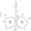
- Fig 2 shows a steel cord 10 of the present invention.
- the steel cord 10 comprises a core filament 12 and a sheath 14.
- the sheath 14 is comprised of three sheath filaments 14A, 14B and 14C.
- the diameter, d, of the core filament 12 is the same as the diameter, D, of each sheath filament 14A, 14B or 14C.
- Fig. 1 shows the core filament 12.
- the core filament 12 alternately has straight portions 16, whose axes are disposed on one line, and protrusions 18 formed by bending.
- the length of each straight portion 16 is the same and the length of each protrusion 18 is the same in the longitudinal direction of the core filament 12.
- the adjacent protrusions 18 are formed so that the direction of the tops of these protrusions 18 are opposite to each other.
- Each of the protrusions 18 has the same height, which is a height sufficient to allow each protrusion 18 to be interposed between any two of the sheath filaments 14A, 14B and 14C.
- the sheath filaments 14A, 14B and 14C are wound around the core filament 12 so that the twisting pitch of the sheath filaments 14A, 14B and 14C is substantially the same as the length between adjacent protrusions 18 which are disposed on the same side of the core filament 12, as shown in Fig. 2.
- the steel cord 10 satisfies the following formulas (1) to (3). 0.1D ⁇ H ⁇ D 0.14P ⁇ L ⁇ 0.2P 0.95P ⁇ C ⁇ 1.05P
- H is the height of each protrusion 18 in the direction perpendicular to the longitudinal direction of the core filament 12 and L is the length of each protrusion 18 in the longitudinal direction of the core filament 12, and P is the twisting pitch of the sheath 14, and C is the distance between adjacent protrusions 18 which are disposed on the same side of the core filament 12.
- the effect of reducing elongation under tensile load also deteriorates when the distance C between adjacent protrusions 18 which are disposed on the same side of the core filament 12 is shortened.
- the distance C is too large, the tensile stress generated in the core filament 12 by tensile load applied to the steel cord 10 exceeds the tensile stress in the sheath filaments 14A, 14B and 14C. This may cause earlier breakage of the core filament 12 under repetitive load, such as a load which is generated in a rolling tire, resulting in undesirable degradation of fatigue resistance of a rubber product reinforced by the steel cord 10. Therefore, it is preferable that distance C is almost same as the twisting pitch P and satisfies 0.95P ⁇ C ⁇ 1.05P.
- the length of each straight portion 16 is more than 30% of the twisting pitch P of the sheath 14.
- each straight portion 16 can have a different length.
- each protrusion 18 can have a different length and a different height.
- each filament that is, the core filament 12 or the sheath filament 14A, 14B or 14C
- each filament can have a different diameter.
- the number of sheath filaments is preferably 2 to 4 in order to maintain gaps between adjacent filaments even when all of the sheath filaments come into contact with the core filament.
- the protrusions 18 may be formed on the same side or on all sides of the core filament 12. However, it is preferable that adjacent protrusions 18 are formed on opposite sides of the core filament 12, because it is easy to produce such a core filament and it is undesirable for open gaps to collect on only one side of the core filament 12.
- each protrusion 18 shown in Fig. 1 is formed by angular bending portions
- the protrusions used in the present invention can be any shape provided that the protrusions can be interposed between the sheath filaments 14A, 14B and 14C. Therefore, protrusions formed by curved bending portions can be used in the present invention.
- a forming device 26 shown in Fig. 3 can be used for the production of the core filament 12.
- the forming device 26 includes a pair of forming rollers 24 on the periphery of which concave portions 20 and convex portions 22 are provided.
- the core filament 12 can be prepared by supplying a filament from a bobbin of a twisting machine (not shown) to the pair of forming rollers 24, and passing the filament between the pair of forming rollers 24 to bend it by the engagement of concave portion 20 and convex portion 22, as shown in Fig. 3, for the preparation of the protrusions 18.
- the sheath filaments 14A, 14B and 14C will be wound around the core filament 12 thus obtained to form the steel cord 10.
- the steel cord 10 can be used in parts of tires, such as a carcass, a belt layer and the like.
- each steel cord shown in Table 1 was composed of four filaments each having a diameter of 0.26 mm. Moreover, the steel cords in Table 1 had the same twisting pitch of 12.0 mm.
- Comparative Example 1 had a 1 ⁇ 4 open structure having open gaps between adjacent sheath filaments as shown in Fig. 5.
- Comparative Example 2 had a conventional 1 ⁇ 4 closed structure having no open gaps between adjacent sheath filaments as shown in Fig. 7. Further, Comparative Example 3 had a 1+3 structure with the core filament having a continuous wave form as shown in Fig. 6.
- Examples 1 to 4 were steel cords according to the present invention (Fig. 2) and had a core filament alternately having straight portions, whose axes were disposed on one line, and protrusions formed by bending as shown in Fig. 1.
- the adjacent protrusions were disposed on opposite sides of the core filament, the length of each straight portion was the same, the length of each protrusion was the same, and the height of each protrusion was the same.
- the length L of each protrusion and the distance C between the adjacent protrusions which were disposed on the same side of the core filament were within the respective preferred ranges, but the height H of each protrusion was larger than the upper limit of the preferred range of H.
- Example 2 the height H and the distance C were within the respective preferred ranges, but were the smallest among Examples 1 to 4. In addition, the length L fell outside of the preferred range of L in Example 2. In Example 3, the height H and the length L were within the respective preferred ranges, but the distance C was longer than the upper limit of the preferred range of C and about twice as long as the length of the twisting pitch of the sheath. Example 4 satisfied the above three conditions.
- Tires (tire size: 205/R15) of the present invention were prepared. As shown in Fig. 4, each tire 28 comprised a carcass 32 having a toroidal shape extending over a pair of beads 34, and two belt layers 30 reinforcing the crown portion of the carcass 32, and one type of the above steel cords was used in the belt layers 30.
- the belt layers 30 comprised a plurality of steel cords which were parallel to each other. The steel cords of each of the belt layers 30 were set at an angle of 20 degrees with respect to the equatorial plane of the tire 28. Further, the two belt layers 30 were disposed so that the axes of the steel cords of one of the belt layers 30 intersected the axes of the steel cords of the other belt layer 30.
- Test items are as follows:
- the first set of five pitches were the first through fifth pitches of the steel cord
- the second set was the second through sixth pitches
- the last set of five pitches was the pitches X-4, X-3, X-2, X-1, X, wherein X represent the final twisting pitch of the steel cord.
- the steel cord was given the evaluation mark B if there were one or more cross-sectional areas with full penetration of rubber in each set of five twisting pitches.
- the steel cord was given the evaluation mark C if there was at least one set of five twisting pitches in which there were no cross-sectional areas at which rubber penetrated all the gaps. The result "B" is acceptable in practical use.
- a belt layer was sampled from each tire and the arrangements of the steel cords in the belt layer were evaluated by observing an X-ray transmission image.
- Comparative Example 3 with a 1+3 structure and a core filament having a continuous wave form, the result was better than that of Comparative 1 and expressed by "B".
- the two results were used as criteria and, as for other samples, if the result was similar to that of Comparative Example 1 or 3, it is expressed by "C” or "B” and if the result was better than that of Comparative Example 3, it is expressed by "A”.
- Examples 1 to 4 show good penetration of rubber, and the tires using these steel cords shows good resistance to separation caused by cut of the tread, which was not achieved by Comparative Example 2.
- the diameters of the steel cords of Examples 1 to 4 were much smaller than that of Comparative Example 3 which showed reasonable results for all the parameters evaluated except for P.L.E.
- the thickness of the belt layer comprising the steel cords of any type of Comparative Examples 1 to 4 were thinner than that comprising the steel cord of Comparative Example 3, resulting in lighter tires.
- Example 4 which satisfied all the preferred conditions showed the best compatibility for parameters evaluated.
Abstract
Description
- The present invention relates to a steel cord for reinforcing a rubber product, having good penetration of rubber and high rigidity, and to a pneumatic tire having improved durability, steering stability and uniformity through the use of this steel cord as a reinforcing member.
- In the field of steel cords for reinforcing rubber products such as tires, steel cords into which an elastic material such as rubber can penetrate have been proposed in order to improve the durability of rubber products reinforced by the steel cords.
- For example, as shown in Fig. 5, an
open cord 100 has been proposed which is composed offilaments 102 twisted together in large spirals withgaps 104 therebetween in order to permit penetration of rubber into thecord 100. - However, the
open cord 100 has drawbacks caused by its low rigidity due to thefilaments 102 being twisted together in large spirals. For example, it is difficult to maintain good uniformity of tires when theopen cord 100 is used, because theopen cord 100 can easily elongate under a low tensile load such as that applied to the cord in the production process of tires. - Further, another drawback of the
open cord 100 is that the penetration of rubber is unreliable because thefilaments 102 can easily be made to contact each other due to the tension or compression which arises in the production process of rubber products such as tires. - In order to overcome such drawbacks of the open cord, various steel cords have been proposed.
- For example, a steel cord, which comprises at least one filament having a spiral shape prior to twisting with other filaments and in which these filaments are twisted together such that the twisting pitch of the steel cord is larger than the spiral pitch of said at least one filaments, is disclosed in Japanese Utility Model Application Laid-Open (JP-U) No. 4-60589. Further, a 1+3 structure in which the
core filament 114 has a continuous wave shape (Fig. 6) is disclosed in Japanese Patent Application Laid-Open (JP-A) No. 5-295682. - These steel cords have higher rigidity and exhibit more reliable penetration of rubber than the open cord, and can overcome the drawbacks of the open cord to a certain extent. However, the improvement is not enough to provide excellent steering stability and uniformity for tires, and thus, further improvement are required.
- The present invention has been made in light of the above circumstances, and an object thereof is to provide a steel cord for reinforcing a rubber product having higher rigidity and more reliable penetration of an elastic material such as rubber.
- Another object is to provide a pneumatic tire with improved durability, steering stability and uniformity.
- A steel cord for reinforcing a rubber product according to the present invention comprises a core consisting of one steel filament and a sheath consisting of a plurality of steel filaments wound around the core, with the steel filament forming the core alternately having straight portions, whose axes are disposed on one line, and protrusions formed by bending.
- A pneumatic tire according to the present invention comprises a carcass having a toroidal shape extending over a pair of beads, and at least one belt layer reinforcing the crown portion of the carcass, and the above-described steel cord for reinforcing a rubber product is used in at least one of the carcass and the belt layer.
- The feature of the steel cord of the present invention is the shape of the filament forming the core (hereinafter called " core filament"), that is, the core filament should alternately have straight portions, whose axes are disposed on one (a single) line, and protrusions formed by bending.
- According to the present invention, the protrusions of the core filament prevent the filaments forming the sheath (hereinafter called "sheath filaments) from contacting each other due to the tension or compression which arises in the production process of rubber products such as tires, and thus, penetration of rubber is ensured.
- Moreover, because the core filament has straight portions disposed on one (a single) line parallel to the axis of the cord, steel cord of the present invention exhibits high rigidity and low elongation when a tensile load is applied thereto.
- Therefore, the steel cord of the present invention can provide superior durability, steering stability and uniformity for a tire using the steel cord.
-
- Fig. 1 is a side view of an example of a core filament used in a steel cord of the present invention.
- Fig. 2 illustrates an embodiment of a steel cord of the present invention having the core filament shown in Fig. 1.
- Fig. 3 schematically shows a side view of a device for forming the core filament shown in Fig. 1.
- Fig. 4 is a cross-sectional view of a pneumatic tire of the present invention.
- Fig. 5 is a cross-sectional view of a conventional steel cord having an open structure.
- Fig. 6 is a side view of a core filament having a continuous wave form and used in another conventional steel cord.
- Fig. 7 is a cross-sectional view of another conventional steel cord having a closed structure.
-
- Fig 2 shows a
steel cord 10 of the present invention. Thesteel cord 10 comprises acore filament 12 and asheath 14. Thesheath 14 is comprised of threesheath filaments core filament 12 is the same as the diameter, D, of eachsheath filament - Fig. 1 shows the
core filament 12. Thecore filament 12 alternately hasstraight portions 16, whose axes are disposed on one line, andprotrusions 18 formed by bending. The length of eachstraight portion 16 is the same and the length of eachprotrusion 18 is the same in the longitudinal direction of thecore filament 12. Theadjacent protrusions 18 are formed so that the direction of the tops of theseprotrusions 18 are opposite to each other. Each of theprotrusions 18 has the same height, which is a height sufficient to allow eachprotrusion 18 to be interposed between any two of thesheath filaments - The
sheath filaments core filament 12 so that the twisting pitch of thesheath filaments adjacent protrusions 18 which are disposed on the same side of thecore filament 12, as shown in Fig. 2. - It is preferable that the
steel cord 10 satisfies the following formulas (1) to (3). - In the above formulas, as shown in Fig. 1, H is the height of each
protrusion 18 in the direction perpendicular to the longitudinal direction of thecore filament 12 and L is the length of eachprotrusion 18 in the longitudinal direction of thecore filament 12, and P is the twisting pitch of thesheath 14, and C is the distance betweenadjacent protrusions 18 which are disposed on the same side of thecore filament 12. - The reason for this is as follows: when H is less than 0.1D, the
protrusions 18 are barely interposed between two of thesheath filaments sheath filaments core filament 12. As a result, rubber penetrates into thesteel cord 10 less reliably. In contrast, when H exceeds D, thesteel cord 10 becomes too large and the thickness of the rubber which covers thesteel cord 10 must be increased, resulting in increase in weight of the rubber product. - In addition, when L is less than 0.14P, it is difficult to form
protrusions 18 which are large enough to be interposed between two of thesheath filaments protrusions 18 become too large, and the effect of reducing elongation of thesteel cord 10 under low tensile load due to the existence of thestraight portion 16 deteriorates. - The effect of reducing elongation under tensile load also deteriorates when the distance C between
adjacent protrusions 18 which are disposed on the same side of thecore filament 12 is shortened. However, when the distance C is too large, the tensile stress generated in thecore filament 12 by tensile load applied to thesteel cord 10 exceeds the tensile stress in thesheath filaments core filament 12 under repetitive load, such as a load which is generated in a rolling tire, resulting in undesirable degradation of fatigue resistance of a rubber product reinforced by thesteel cord 10. Therefore, it is preferable that distance C is almost same as the twisting pitch P and satisfies 0.95P ≤ C ≤ 1.05P. - In the present invention, it is preferable that the length of each
straight portion 16 is more than 30% of the twisting pitch P of thesheath 14. - In the present invention, each
straight portion 16 can have a different length. Similarly, eachprotrusion 18 can have a different length and a different height. However, it is preferable that the length of eachstraight portion 16 is the same and that eachprotrusion 16 has the same length and the same height. This makes production easier. - In addition, each filament, that is, the
core filament 12 or thesheath filament - Further, the
protrusions 18 may be formed on the same side or on all sides of thecore filament 12. However, it is preferable thatadjacent protrusions 18 are formed on opposite sides of thecore filament 12, because it is easy to produce such a core filament and it is undesirable for open gaps to collect on only one side of thecore filament 12. - Moreover, though each
protrusion 18 shown in Fig. 1 is formed by angular bending portions, the protrusions used in the present invention can be any shape provided that the protrusions can be interposed between thesheath filaments - For the production of the
core filament 12, a formingdevice 26 shown in Fig. 3 can be used. The formingdevice 26 includes a pair of formingrollers 24 on the periphery of whichconcave portions 20 and convexportions 22 are provided. Thecore filament 12 can be prepared by supplying a filament from a bobbin of a twisting machine (not shown) to the pair of formingrollers 24, and passing the filament between the pair of formingrollers 24 to bend it by the engagement ofconcave portion 20 and convexportion 22, as shown in Fig. 3, for the preparation of theprotrusions 18. Thesheath filaments core filament 12 thus obtained to form thesteel cord 10. - The
steel cord 10 can be used in parts of tires, such as a carcass, a belt layer and the like. - In order to assess the effect of the present invention, examples according to the invention and comparative examples, as shown in Table 1, were prepared. Each steel cord shown in Table 1 was composed of four filaments each having a diameter of 0.26 mm. Moreover, the steel cords in Table 1 had the same twisting pitch of 12.0 mm.
- Comparative Example 1 had a 1 × 4 open structure having open gaps between adjacent sheath filaments as shown in Fig. 5.
- Comparative Example 2 had a conventional 1 × 4 closed structure having no open gaps between adjacent sheath filaments as shown in Fig. 7. Further, Comparative Example 3 had a 1+3 structure with the core filament having a continuous wave form as shown in Fig. 6.
- Examples 1 to 4 were steel cords according to the present invention (Fig. 2) and had a core filament alternately having straight portions, whose axes were disposed on one line, and protrusions formed by bending as shown in Fig. 1. In each core filament of Examples 1 to 4, the adjacent protrusions were disposed on opposite sides of the core filament, the length of each straight portion was the same, the length of each protrusion was the same, and the height of each protrusion was the same. In Example 1, the length L of each protrusion and the distance C between the adjacent protrusions which were disposed on the same side of the core filament were within the respective preferred ranges, but the height H of each protrusion was larger than the upper limit of the preferred range of H. In Example 2, the height H and the distance C were within the respective preferred ranges, but were the smallest among Examples 1 to 4. In addition, the length L fell outside of the preferred range of L in Example 2. In Example 3, the height H and the length L were within the respective preferred ranges, but the distance C was longer than the upper limit of the preferred range of C and about twice as long as the length of the twisting pitch of the sheath. Example 4 satisfied the above three conditions.
- Tires (tire size: 205/R15) of the present invention were prepared. As shown in Fig. 4, each
tire 28 comprised acarcass 32 having a toroidal shape extending over a pair ofbeads 34, and twobelt layers 30 reinforcing the crown portion of thecarcass 32, and one type of the above steel cords was used in the belt layers 30. The belt layers 30 comprised a plurality of steel cords which were parallel to each other. The steel cords of each of the belt layers 30 were set at an angle of 20 degrees with respect to the equatorial plane of thetire 28. Further, the twobelt layers 30 were disposed so that the axes of the steel cords of one of the belt layers 30 intersected the axes of the steel cords of theother belt layer 30. - Test items are as follows:
- Increase in elongation of the steel cord was measured when tensile load on the cord was increased from 0.5 kg to 5 kg. This parameter is commonly known as "Part Load Elongation (P.L.E.)" A small value is desirable for this parameter. In Table 1, the test results are expressed by relative values when the value of Comparative Example 2 is set at 100.
- A piece of steel cord was sampled from the belt layer of each vulcanized tire, and the cross-sectional area of the cord over the entire length thereof was observed over every 1mm. In Table 1, the result is expressed by "A" if, at every twisting pitch of the sheath, there were one or more cross-sectional areas at which the rubber penetrated all the gaps. Then, rather than observing the cross-sectional areas per twisting pitch, cross-sectional areas over respective sets of five pitched were observed. For example, the first set of five pitches were the first through fifth pitches of the steel cord, the second set was the second through sixth pitches, and the last set of five pitches was the pitches X-4, X-3, X-2, X-1, X, wherein X represent the final twisting pitch of the steel cord. The steel cord was given the evaluation mark B if there were one or more cross-sectional areas with full penetration of rubber in each set of five twisting pitches. The steel cord was given the evaluation mark C if there was at least one set of five twisting pitches in which there were no cross-sectional areas at which rubber penetrated all the gaps. The result "B" is acceptable in practical use.
- A belt layer was sampled from each tire and the arrangements of the steel cords in the belt layer were evaluated by observing an X-ray transmission image. The uniformity of the arrangement of the steel cord in Comparative Example 1, with a 1 × 4 open structure, was worst and expressed by "C" in Table 1. In Comparative Example 3 with a 1+3 structure and a core filament having a continuous wave form, the result was better than that of Comparative 1 and expressed by "B". The two results were used as criteria and, as for other samples, if the result was similar to that of Comparative Example 1 or 3, it is expressed by "C" or "B" and if the result was better than that of Comparative Example 3, it is expressed by "A".
- After running 50,000 km on a rough road, it was determined whether there was a cut which was formed in the tread and which reached the steel cord embedded in the belt layer. If there was such a cut, the maximum length of the corroded portion of each filament caused by the cut was measured. The shorter the maximum length of the corrosion, the better the resistance to separation caused by cut of the tread. The result of Comparative Example 1 was the best and is expressed by "A" in Table 1. On the other hand, the result of Comparative Example 2 was the worst and is expressed by "C". The two results are used as criteria and, as for other samples, if the result was similar to that of Comparative Example 1 or 2, it is expressed by "A" or "C" and if the result was better than that of Comparative Example 2 and was worse than that Comparative Example 1, it is expressed by "B". The result "B" is acceptable in practical use.
- The results are shown in Table 1.

- As shown in Table 1, the amounts of elongation under low tensile load (P.L.E.) of the steel cords of Examples 1 to 4 are smaller than those of both Comparative Examples 1 and 3, and are similar to that of Comparative Example 2. Further, the results of uniformity of tires of Examples 1 to 4 are as good as that of Comparative Example 2, owing to their good workability and stable form.
- In addition to the good characteristics of elongation under low tensile load, Examples 1 to 4 show good penetration of rubber, and the tires using these steel cords shows good resistance to separation caused by cut of the tread, which was not achieved by Comparative Example 2.
- Further, the diameters of the steel cords of Examples 1 to 4 were much smaller than that of Comparative Example 3 which showed reasonable results for all the parameters evaluated except for P.L.E. As a result, the thickness of the belt layer comprising the steel cords of any type of Comparative Examples 1 to 4 were thinner than that comprising the steel cord of Comparative Example 3, resulting in lighter tires.
- Among Examples 1 to 4 , Example 4 which satisfied all the preferred conditions showed the best compatibility for parameters evaluated.
Claims (8)
- A steel cord for reinforcing a rubber product, comprising a core filament consisting of one steel filament and a sheath consisting of a plurality of steel filaments wound around the core,
wherein the steel cord filament forming the core alternately has straight portions, whose axes are disposed on one line, and protrusions formed by bending. - A steel cord for reinforcing a rubber product according to claim 1, wherein each of the protrusions has a height which allows the protrusion to be interposed between the steel filaments forming the sheath.
- A steel cord for reinforcing a rubber product according to claim 2, wherein the adjacent protrusions are disposed on opposite sides of the steel filament forming the core.
- A steel cord for reinforcing a rubber product according to claim 2 or 3, wherein the length of each straight portion is the same, and the length of each protrusion is the same in the longitudinal direction of the core.
- A steel cord for reinforcing a rubber product according to any one of claims 2 through 4, wherein the diameter of the steel filament forming the core is the same as the diameter of each steel filament forming the sheath.
- A steel cord for reinforcing a rubber product according to claim 5, wherein the number of steel filaments forming the sheath is two to four.
- A steel cord for reinforcing a rubber product according to claim 5, wherein given that the diameter of each steel filament forming the sheath is D, the height of each protrusion in the direction perpendicular to the longitudinal direction of the core is H, the length of each protrusion in the longitudinal direction of the core is L, the distance between adjacent protrusions which are disposed on the same side of the core is C, and the twisting pitch of the sheath is P, the following formulas (1) to (3) are satisfied:
- A pneumatic tire comprising a carcass having a toroidal shape extending over a pair of beads, and at least one belt layer reinforcing the crown portion of the carcass,
wherein a steel cord for reinforcing a rubber product according to any one of claims 1 through 7 is used in at least one of the carcass and the belt layer.
Priority Applications (2)
| Application Number | Priority Date | Filing Date | Title |
|---|---|---|---|
| EP97307057A EP0905305A1 (en) | 1997-09-11 | 1997-09-11 | Steel cord for reinforcing rubber product and pneumatic tyre using such steel cords |
| US08/956,706 US5911675A (en) | 1997-09-11 | 1997-10-23 | Steel cord for reinforcing rubber product and pneumatic tire using such steel cord |
Applications Claiming Priority (2)
| Application Number | Priority Date | Filing Date | Title |
|---|---|---|---|
| EP97307057A EP0905305A1 (en) | 1997-09-11 | 1997-09-11 | Steel cord for reinforcing rubber product and pneumatic tyre using such steel cords |
| US08/956,706 US5911675A (en) | 1997-09-11 | 1997-10-23 | Steel cord for reinforcing rubber product and pneumatic tire using such steel cord |
Publications (1)
| Publication Number | Publication Date |
|---|---|
| EP0905305A1 true EP0905305A1 (en) | 1999-03-31 |
Family
ID=26147600
Family Applications (1)
| Application Number | Title | Priority Date | Filing Date |
|---|---|---|---|
| EP97307057A Withdrawn EP0905305A1 (en) | 1997-09-11 | 1997-09-11 | Steel cord for reinforcing rubber product and pneumatic tyre using such steel cords |
Country Status (2)
| Country | Link |
|---|---|
| US (1) | US5911675A (en) |
| EP (1) | EP0905305A1 (en) |
Cited By (1)
| Publication number | Priority date | Publication date | Assignee | Title |
|---|---|---|---|---|
| KR100567812B1 (en) | 2004-12-31 | 2006-04-05 | 주식회사 효성 | Single wire steel cord |
Families Citing this family (7)
| Publication number | Priority date | Publication date | Assignee | Title |
|---|---|---|---|---|
| KR100916917B1 (en) * | 2007-11-06 | 2009-09-09 | 주식회사 효성 | Single wire steel cord |
| CN105040494B (en) * | 2009-01-09 | 2017-08-08 | 贝卡尔特公司 | All-steel cord for strengthening tire |
| CN109822008B (en) * | 2013-07-29 | 2021-06-18 | 贝卡尔特公司 | Straight monofilaments for use in belt plies |
| EP3420137A1 (en) * | 2016-02-23 | 2019-01-02 | NV Bekaert SA | Energy absorption assembly |
| US10246823B2 (en) * | 2016-07-11 | 2019-04-02 | Hall Labs Llc | Compressible rope |
| DE102016225234A1 (en) * | 2016-11-25 | 2018-05-30 | Continental Reifen Deutschland Gmbh | Pneumatic vehicle tire with a belt layer comprising steel reinforcement |
| CN112647328A (en) * | 2020-12-28 | 2021-04-13 | 江苏兴达钢帘线股份有限公司 | Steel cord and preparation process thereof |
Citations (5)
| Publication number | Priority date | Publication date | Assignee | Title |
|---|---|---|---|---|
| US5020312A (en) * | 1989-05-23 | 1991-06-04 | Kokoku Steel Wire Ltd. | Tire steel cords and method of manufacturing thereof |
| EP0462716A1 (en) * | 1990-06-16 | 1991-12-27 | Tokusen Kogyo Company Limited | Steel cord for reinforcing rubber product |
| EP0551124A2 (en) * | 1992-01-09 | 1993-07-14 | Bridgestone Corporation | Steel cord |
| EP0566350A1 (en) * | 1992-04-17 | 1993-10-20 | Bridgestone Corporation | Steel cords for elastomer articles and pneumatic radial tires using the same |
| JPH05295682A (en) * | 1992-04-17 | 1993-11-09 | Bridgestone Corp | Steel cord for reinforcing elastomer product |
Family Cites Families (9)
| Publication number | Priority date | Publication date | Assignee | Title |
|---|---|---|---|---|
| USH1333H (en) * | 1990-03-21 | 1994-07-05 | Helfer Farrel B | High strength reinforcement |
| US5337549A (en) * | 1989-12-20 | 1994-08-16 | Tokusen Kogyo Company Limited | Steel cord for reinforcement of rubber products |
| JPH0460589A (en) * | 1990-06-29 | 1992-02-26 | Hitachi Ltd | Divisional scrolling system |
| JPH04281081A (en) * | 1991-03-06 | 1992-10-06 | Bridgestone Corp | Metallic cord for reinforcing rubber and tire using the same |
| JPH05302282A (en) * | 1992-04-24 | 1993-11-16 | Bridgestone Corp | Steel cord for reinforcing rubber article and pneumatic radial tire for heavy load |
| JP3222257B2 (en) * | 1993-04-09 | 2001-10-22 | 株式会社ブリヂストン | Steel cord for reinforcing rubber articles and pneumatic radial tire using the same |
| JP3517244B2 (en) * | 1993-12-15 | 2004-04-12 | ナムローゼ・フェンノートシャップ・ベーカート・ソシエテ・アノニム | Steel cord structure with gap |
| WO1995018259A1 (en) * | 1993-12-27 | 1995-07-06 | Tokyo Rope Manufacturing Co., Ltd. | Steel cord and radial tire using the same as a reinforcing material |
| US5661966A (en) * | 1996-06-27 | 1997-09-02 | Tokyo Rope Manufacturing Co. Ltd. | Steel cord for reinforcement of off-road tire, method of manufacturing the same, and off-road tire |
-
1997
- 1997-09-11 EP EP97307057A patent/EP0905305A1/en not_active Withdrawn
- 1997-10-23 US US08/956,706 patent/US5911675A/en not_active Expired - Fee Related
Patent Citations (5)
| Publication number | Priority date | Publication date | Assignee | Title |
|---|---|---|---|---|
| US5020312A (en) * | 1989-05-23 | 1991-06-04 | Kokoku Steel Wire Ltd. | Tire steel cords and method of manufacturing thereof |
| EP0462716A1 (en) * | 1990-06-16 | 1991-12-27 | Tokusen Kogyo Company Limited | Steel cord for reinforcing rubber product |
| EP0551124A2 (en) * | 1992-01-09 | 1993-07-14 | Bridgestone Corporation | Steel cord |
| EP0566350A1 (en) * | 1992-04-17 | 1993-10-20 | Bridgestone Corporation | Steel cords for elastomer articles and pneumatic radial tires using the same |
| JPH05295682A (en) * | 1992-04-17 | 1993-11-09 | Bridgestone Corp | Steel cord for reinforcing elastomer product |
Cited By (1)
| Publication number | Priority date | Publication date | Assignee | Title |
|---|---|---|---|---|
| KR100567812B1 (en) | 2004-12-31 | 2006-04-05 | 주식회사 효성 | Single wire steel cord |
Also Published As
| Publication number | Publication date |
|---|---|
| US5911675A (en) | 1999-06-15 |
Similar Documents
| Publication | Publication Date | Title |
|---|---|---|
| US4371025A (en) | Reinforcing annular structure of radial tires | |
| CA1246945A (en) | Reinforcing cord with wrap-around wire | |
| US5858137A (en) | Radial tires having at least two belt plies reinforced with steel monofilaments | |
| US4836262A (en) | Metal cords and pneumatic tires using the same | |
| EP0524702A2 (en) | Pneumatic radial tyre | |
| EP0543640B1 (en) | Pneumatic tyre | |
| EP1712376B1 (en) | Pneumatic tyre | |
| EP2065512A1 (en) | Steel cord, composite of rubber and steel cord, and tire | |
| EP2388372B1 (en) | Steel cord for reinforcement of rubber article and pneumatic tire using same | |
| EP0619398B1 (en) | Steel cord for reinforcing rubber articles and pneumatic radial tire using the same | |
| US4172487A (en) | Pneumatic radial tire | |
| EP1126074B1 (en) | Pneumatic tyre | |
| EP1344864B1 (en) | Steel cord, method of making the same and pneumatic tire including the same | |
| JP2006507414A (en) | Flat helically wound tire cord | |
| EP0905305A1 (en) | Steel cord for reinforcing rubber product and pneumatic tyre using such steel cords | |
| US6425428B1 (en) | Steel cord having flat side surface portion, method of manufacturing same, and pneumatic tire reinforced with same | |
| EP0604228B1 (en) | Pneumatic tyre | |
| EP0515178B1 (en) | Pneumatic tyre | |
| JPH0665877A (en) | Steel cord for reinforcing belt part of pneumatic tire for middle or heavy load | |
| EP0781883B1 (en) | Steel cord for reinforcing a rubber product and pneumatic tire using the same | |
| JP4578200B2 (en) | Steel cord for reinforcing rubber articles and pneumatic tire using the same | |
| JP2000177311A (en) | Pneumatic radial tire | |
| EP0206976A2 (en) | Pneumatic tyres and reinforcements therefor | |
| JPH07189143A (en) | Steel cord for reinforcement of rubber good and pneumatic radial tire | |
| JP2001003280A (en) | Steel cord for reinforcing rubber product and pneumatic radial tire |
Legal Events
| Date | Code | Title | Description |
|---|---|---|---|
| PUAI | Public reference made under article 153(3) epc to a published international application that has entered the european phase |
Free format text: ORIGINAL CODE: 0009012 |
|
| AK | Designated contracting states |
Kind code of ref document: A1 Designated state(s): BE ES FR GB IT |
|
| 17P | Request for examination filed |
Effective date: 19990909 |
|
| AKX | Designation fees paid |
Free format text: BE ES FR GB IT |
|
| REG | Reference to a national code |
Ref country code: DE Ref legal event code: 8566 |
|
| RAP1 | Party data changed (applicant data changed or rights of an application transferred) |
Owner name: BRIDGESTONE CORPORATION |
|
| 17Q | First examination report despatched |
Effective date: 20010822 |
|
| STAA | Information on the status of an ep patent application or granted ep patent |
Free format text: STATUS: THE APPLICATION IS DEEMED TO BE WITHDRAWN |
|
| 18D | Application deemed to be withdrawn |
Effective date: 20021113 |