EP0904779B1 - Iontophoretic patch with hydrogel reservoir - Google Patents
Iontophoretic patch with hydrogel reservoir Download PDFInfo
- Publication number
- EP0904779B1 EP0904779B1 EP98307962A EP98307962A EP0904779B1 EP 0904779 B1 EP0904779 B1 EP 0904779B1 EP 98307962 A EP98307962 A EP 98307962A EP 98307962 A EP98307962 A EP 98307962A EP 0904779 B1 EP0904779 B1 EP 0904779B1
- Authority
- EP
- European Patent Office
- Prior art keywords
- reservoir
- water soluble
- drug
- hydrogel
- ion
- Prior art date
- Legal status (The legal status is an assumption and is not a legal conclusion. Google has not performed a legal analysis and makes no representation as to the accuracy of the status listed.)
- Expired - Lifetime
Links
Images

Classifications
-
- A—HUMAN NECESSITIES
- A61—MEDICAL OR VETERINARY SCIENCE; HYGIENE
- A61N—ELECTROTHERAPY; MAGNETOTHERAPY; RADIATION THERAPY; ULTRASOUND THERAPY
- A61N1/00—Electrotherapy; Circuits therefor
- A61N1/02—Details
- A61N1/04—Electrodes
- A61N1/0404—Electrodes for external use
- A61N1/0408—Use-related aspects
- A61N1/0428—Specially adapted for iontophoresis, e.g. AC, DC or including drug reservoirs
- A61N1/0448—Drug reservoir
-
- A—HUMAN NECESSITIES
- A61—MEDICAL OR VETERINARY SCIENCE; HYGIENE
- A61K—PREPARATIONS FOR MEDICAL, DENTAL OR TOILETRY PURPOSES
- A61K9/00—Medicinal preparations characterised by special physical form
- A61K9/0002—Galenical forms characterised by the drug release technique; Application systems commanded by energy
- A61K9/0009—Galenical forms characterised by the drug release technique; Application systems commanded by energy involving or responsive to electricity, magnetism or acoustic waves; Galenical aspects of sonophoresis, iontophoresis, electroporation or electroosmosis
-
- A—HUMAN NECESSITIES
- A61—MEDICAL OR VETERINARY SCIENCE; HYGIENE
- A61N—ELECTROTHERAPY; MAGNETOTHERAPY; RADIATION THERAPY; ULTRASOUND THERAPY
- A61N1/00—Electrotherapy; Circuits therefor
- A61N1/02—Details
- A61N1/04—Electrodes
- A61N1/0404—Electrodes for external use
- A61N1/0408—Use-related aspects
- A61N1/0428—Specially adapted for iontophoresis, e.g. AC, DC or including drug reservoirs
- A61N1/0444—Membrane
Definitions
- the present invention relates to an iontophoretic patch for the transdermal delivery of drugs, with an improved hydrogel reservoir.
- iontophoresis is the introduction by means of electric current, of ions of soluble salts into the tissues of the body for therapeutic purposes.
- at least two electrodes are used. Both of these electrodes are positioned to be in intimate electrical contact with some portion of the skin of the body.
- One electrode called the active or donor electrode, is the electrode from which the ionic substance, medicament, drug precursor or drug is delivered into the body by iontophoresis.
- the other electrode called the counter or return electrode, serves to close the electrical circuit through the body.
- the circuit is completed by connection of the electrodes to a source of electrical energy, e.g., a battery.
- a source of electrical energy e.g., a battery.
- the anode will be the active electrode and the cathode will serve to complete the circuit.
- the cathode will be the active electrode and the anode will be the counter electrode.
- both the anode and cathode may be used to deliver drugs of opposite charge into the body.
- both electrodes are considered to be active or donor electrodes.
- the anode can deliver a positively charged ionic substance into the body while the cathode can deliver a negatively charged ionic substance into the body.
- Electroosmosis is transdermal flux of a liquid solvent (e.g., the liquid solvent containing the uncharged drug or agent) which is induced by the presence of an electric field imposed across the skin by the donor electrode.
- a liquid solvent e.g., the liquid solvent containing the uncharged drug or agent
- the terms "iontophoresis” and “iontophoretic” apply equally to electrically powered devices which deliver charged/ionic agents by iontophoresis as well as to electrically powered devices which deliver uncharged/nonionic agents by electroosmosis.
- a matrix of reservoirs to hold the drug or medicament, or beneficial agent is provided.
- a reservoir can be of any material adapted to absorb and hold a sufficient quantity of liquid therein in order to permit transport of agent therethrough by iontophoresis.
- a matrix of reservoirs is used, which is composed at least in part of a hydrophilic polymer.
- the reservoirs In order to conduct electrical current the reservoirs must be sufficiently hydrated to allow ions to flow therethrough. In most cases the liquids used to hydrate the matrices of the reservoirs will be water, but other liquids can also be used to activate the matrices of the reservoirs.
- the combination of water soluble polymer and water or liquid results in the reservoir containing a hydrogel.
- Electrical current is applied to the reservoir by means of a current distributing member.
- This member can take the form of a metal plate, a foil layer, a screen or a dispersion of particles.
- Use of sacrificial current distributing members which are oxidized or reduced during drug delivery are preferred.
- such devices produce ions, such as silver ions, which cannot be permitted to be transferred to the skin due to adverse affects.
- a significant build-up of ions be permitted because the efficiency of the iontophoresis device may be impeded due to competition with the drug ion.
- the reservoir also to contain a counter-ion to react with the electrochemically generated ion.
- many drug salts do not possess the proper ion for reacting with the electrochemically generated ion.
- water soluble salts would be produced, which would remain in their ionized state in the reservoir. Therefore, it is important to provide a counter-ion in the reservoir which can effectively eliminate the ion generated by the electrode.
- a two compartment model is typically used, comprising a drug reservoir which must be isolated from the second reservoir containing the active electrode by a membrane that prevents direct contact between the drug and the ion exchange media.
- Membranes typically size exclusion membranes, are used to separate the two reservoir compartments.
- the membrane must be selected to prevent the drug ion from migrating into the reservoir containing the active electrode, and also to prevent the ion exchange means from drifting into the drug reservoir.
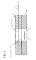
- An example of such a two compartment device is shown in Figure 1.
- a two compartment reservoir 1 is divided into an upper reservoir 2 containing an active electrode 3.
- the reservoirs are situated in a foam ring 6.
- the upper reservoir is separated from a lower reservoir 4 by a separator membrane 5.
- the drug is stored in the lower reservoir.
- the bottom of the lower reservoir is sealed by a release liner 7, which is removed prior to application of the iontophoretic device to a patient.
- Examples of other two compartment membranes may be found in Haak, U.S. Pat. No. 4,927,408 and Phipps, U.S. Pat. No. 5,084,008.
- Phipps it is the drug containing reservoir which is equipped with the counter ion.
- this is accomplished by constructing an electrode having a conductive, current distributing member; means for coupling the current distributing member to a source of electrical current; a reservoir containing an ionic or ionizable drug; an ion source layer in intimate contact with the current distributing member; and a layer of selectively permeable material applied to the ion source layer which is between the current distributing member and the reservoir.
- ion source layers include salt layers, ion exchange resins or chelating agents. Also useful are salts in thin hydrogel material or a substantially dehydrated layer which would absorb a solvent.
- the selectively permeable material is capable of separating materials by charge and or size. The construction of this device is complex, involving many different layers, thus increasing the cost and time for their manufacture.
- Haak discloses a construction where the drug reservior is in contact with a membrane, including a hydrogel, which is loaded with an ion exchange resin or a chelating agent.
- a membrane including a hydrogel, which is loaded with an ion exchange resin or a chelating agent.
- ion exchange media such as a membrane or resin
- restricting the ion exchange capacity of the device to a thin membrane, rather than a large volume of material limits its ion exchange capacity.
- Phipps U.S. 5,423,739 discloses a two layer iontophoretic device, wherein the top layer is referred to as the carrier layer and the bottom layer is the skin-contacting layer.
- the skin contacting layer contains an ionic polymer component.
- the carrier layer includes the drug or active agent, and few or no mobile ionizable substances.
- the mobile ions of the hydrogel in the skin contacting layer have a charge opposite from that of the ionized active agent. This means that the ionized active agent and the polymer backbone have the same charge.
- the two layers are separated by an impermeable barrier and the device only becomes active when this impermeable barrier is breached. Once the impermeable barrier is broken, the ionized active agent and the mobile counter ions are in direct contact with each other. This contact can lead to unwanted interaction between these two elements and adversely affect drug delivery.
- Phipps also suggests that the relatively small counter ion of the ionomeric component in the skin contacting layer can be selected to interact with the electrochemically generated species at the anode or the cathode.
- this arrangement relies on the mobile counter ions being able to come into contact with the electrochemically generated ions in a very complex matrix system. Due to the complexities of various hydrogel systems, one cannot always be assured that the mobile counter ions will encounter and react with the electrochemically generated ions. Further, the unwanted interactions between the ionized active agent and the mobile counter ion also exist in this arrangement.
- Phipps shows examples where the active agent and the ionic polymer backbone are oppositely charged. However, in these instances, the active agent and the ionic polymer are in direct contact with each other in order to convert the active agent to a cationic state.
- the reservoirs containing the active electrode have been known to include water-insoluble, cross-linked ion-exchange resins which serve to bind the ion generated during the iontophoretic process.
- water-insoluble, cross-linked ion-exchange resins which serve to bind the ion generated during the iontophoretic process.
- An example of the use of a non-water soluble ion-exchange resin in a iontophoretic patch reservoir is found in Chien, et al., U.S. Pat. No. 5,250,022.
- WO 95/09670 discloses a two-compartment iontophoretic device comprising first and second layers of hydrophilic gel polymer, separated by a membrane.
- the first layer contains dispersed therein an ion exchange resin.
- EP-A-509122 discloses a single-layer iontophoretic device comprising a single reservoir which can contain polyelectrolyte as a pH buffer.
- Ion-exchange resins which are included in the hydrogel in the reservoir in the prior art, such as those disclosed in Chien, result in the hydrogel reservoir having a non-uniform consistency.
- the resins often settle out of the matrix.
- Very high concentrations of ion exchange resin at the bottom of the reservoir can hinder ion mobility, which can seriously affect the operation of the iontophoretic patch.
- Uniform reservoirs are also difficult to achieve when processing the ion-exchange resins due to the fact that the cross-linked particles behave as a filler, so viscosity increases hyperbolically with particle concentration.
- the matrix can often become very dough-like in preparation. This results in production difficulties, and consequently increases the cost of the product, due to lengthy production times and a high rejection rate of finished product.
- the high viscosity also limits formulation possibilities in designing the drug reservoir.
- Ion-exchange membranes are physical barriers which are not only susceptible to flaws, they can also be damaged, thus potentially greatly diminishing their effectiveness.
- Yet another object of this invention is a hydrogel reservoir matrix for a two compartment iontophoretic patch which is not dependent on a thin physical barrier for ion exchange.
- the present invention provides an iontophoretic device as set out in claim 1 and thus solves the problems of the prior art hydrogel matrices by using water soluble polyelectrolytes as a constituent of the hydrogel reservoirs in two compartment iontophoretic patches.
- These polyelectrolytes are selected to have a fixed counter-ion on the polymer chain which can bind a suitably charged ion (i.e. ion exchange).
- the most common ion for which such an interaction is useful is the silver ion generated at a silver electrode during iontophoresis.
- the polyelectrolyte is chosen so that it is miscible with or even soluble with the polymers that make up the hydrogel phase in the hydrogel reservoir. In such a case, the polyelectrolyte becomes dispersed on a very small scale level.
- the present invention is directed to an improvement in the hydrogel reservoir of an iontophoretic patch.
- the improvement resides in the use of a water soluble polyelectrolyte in the reservoir to bind ions generated during electrophoresis.
- a polymer By relying on a polymer to bind these ions in such a complex system, rather than small mobile ions, the dependability of the system is enhanced.
- the reservoir itself must be hydrated. Moreover, the reservoir is in the form of a matrix. Most preferably, the matrix of reservoirs is composed of a matrix-forming material. This matrix forming material is, at least in part, composed of a hydrophilic polymer material. Both natural and synthetic hydrophilic polymers may be used.
- Suitable hydrophilic polymers include polyvinylpyrrolidones, polyvinyl alcohol, polyethylene oxides such as Polyox® manufactured by Union Carbide Corp.; Carbopol® manufactured by BF Goodrich of Akron, Ohio; blends of polyoxyethylene or polyethylene glycols with polyacrylic acid such as Polyox® blended with Carbopol®, polyacrylamide, Klucel®, cross-linked dextran such as Sephadex (Pharmacia Fine Chemicals, AB, Uppsala, Sweden); Water Lock® (Grain Processing Corp., Muscatine, Iowa) which is a starch-graft-poly(sodium acrylate-co-acrylamide)polymer; cellulose, derivatives such as hydroxyethyl cellulose, hydroxypropylmethylcellulose, low substituted hydroxypropylcellulose, and cross-linked Na-carboxymethylcellulose such as Ac-Di-Sol (FMC Corp., Philadelphia, Pa.); hydrogels such as polyhydroxyethyl me
- the reservoirs In order to conduct electrical current, the reservoirs must be sufficiently hydrated to allow ions to flow therethrough.
- the liquid used to hydrate the matrices of the reservoirs will be water, but other non-aqueous liquids, can also be used to "hydrate" (i.e., activate) the matrices of the reservoirs.
- the matrices of the reservoirs In the typical case where the hydrating liquid is water, the matrices of the reservoirs will be at least partly composed of a hydrophilic material such as a hydrophilic polymer, a cellulose sponge or pad or other water retaining material. Most preferably, the matrices of the reservoirs will be at least partly composed of a hydrophilic polymer of the type described hereinbefore.
- polyelectrolyte denotes a class of macromolecular compounds, which, when dissolved in a suitable polar solvent, such as water, spontaneously acquire or can be made to acquire a large number of elementary charges distributed along the macromolecular chain.
- the water soluble polyelectrolytes used in the present invention are selected so that the fixed ion on the polymer chain can bind a suitably charged ion generated by the electode during iontophoresis.
- the polyelectrolyte is chosen so that it is miscible with or even soluble with the polymers that make up the hydrogel phase in the matrx.
- polyelectrolyte selected is that it must be medically acceptable. For example, a polyelectrolyte with Hg or Ag ions would not be acceptable. Further, the polyelectrolyte must be medical grade, so that no harmful solvents or residual monomers are incorporated into the iontophoretic patch.
- the polymer selected also should not be cross-linked, and should have a molecular weight of about 1,000 or greater.
- Polyelectrolytes with strongly ionic groups such as sulfonates, carboxylates and phosphates may be used.
- Examples of polyelectrolytes which are suitable for use in the present invention are the high molecular weight cations dextran carbonates, aminated styrenes, polyvinylimine, polyethyleneimine, poly(vinyl 4-alkylpyridinium), and poly(vinylbenzyltrimethyl ammonium).
- Suitable high molecular weight anions include polymethacrylates, polystyrene sulfonates, hyaluronate, alginate, dextran sulfonates, acrylamido methyl propane sulfonates ("poly-AMPS”), and sodium polystyrene sulfonate (“NaPSS”).
- poly-AMPS acrylamido methyl propane sulfonates
- NaPSS sodium polystyrene sulfonate
- the anionic compounds are preferred, with poly-AMPS and NaPSS being more preferred.
- the most preferred water soluble polyelectrolyte is NaPSS, which is available under the trademark Kayexalate from Spectrum Chemical Mfg. Corp. This polyelectrolyte is the sodium form of a sulfonated divinylbenzene styrene copolymer.
- Amberlite IRP-69 is a pharmaceutical grade cation exchange resin available from Rohm and Haas Company. It is supplied as a dry, fine powder and is derived from a sulfonated copolymer of styrene and divinylbenzene. Combination of 15% of this resin with 15% polyvinylpyrrolidone and 70% water to form a hydrogel matrix for iontophoretic drug delivery presents rheological problems. If the total solids content is above about 35%, the mixture becomes highly viscous and difficult to process.
- the amount of PVP is too low, the ion-exchange resin will settle out of the mixture. That means that for some drugs, it is not possible to add enough ion exchange resin without making the reservoir very large. The drug reservoir cannot become too large because that increases the dilution of the drug and tends to decrease the dose efficiency of the patch.
- Tackiness is an important feature of a hydrogel reservoir because a non-sticky hydrogel can separate from the electrodes and cause failure of the device.
- a similar reservoir made using the water soluble NaPSS polyelectrolyte of the present invention is sufficiently tacky to avoid problems of separation.
- the composition is not too viscous, does not separate on standing and is easier to process.
- the amount of polymer or other substance used to form the reservoir matrix can vary, but is typically about 1 to about 50%.
- the amount of water soluble polyelectrolyte contained in the hydrogel matrix reservoir can be from 1-100% of the matrix, with 10-100% being the preferred range.
- the higher range of water soluble polyelectrolyte is suitable in the instance where the polyelectrolyte is capable of forming a gel by itself.
- Any drug capable of iontophoretic delivery may be used in the present invention.
- drugs used in pain management such as morphine, sufentanil, remifentanil, Ketorolac®, butorphanol, fentanyl, hydromorphone, oxymorphone and buprenorphine are useful in the invention.
- Anti-emetics such as ondansetron, granisetron, and metoclopramide may be used.
- Migraine treatments including dihydroergotamine, 311C naratriptan and sumatriptan may also be used.
- Drugs which may be classified as peptides are also capable of iontophoretic delivery.
- examples of such compounds include calcitonin used to treat osteoporosis, octreotide, which is used to counteract the effects of growth hormone and enkephalins, endorphins, and analogs for pain management.
- drugs which would be useful in the present invention include, but are not limited to, analgesics, antithrombotics, anticonvulsants, antidepressants, antiinflammatory agents, antiobesity agents and antipsychotics.
- Other classes of drugs which would find utility in the present invention are known to those familiar with iontophoretic drug delivery.
- the two compartments of the iontophoretic patch can be separated by a number of methods disclosed in the prior art, as previously described.
- permeable, size exclusion membranes are the preferred means of separating the reservoir containing the active electrode and the drug reservoir.
- the size exclusion membrane must be capable of preventing drug molecules from diffusing into the reservoir containing the active electrode, and also of preventing ion exchange polyelectrolytes from diffusing down into the drug reservoir, yet permit the passage of small ions necessary for the iontophoretic process to take place.
- the drug molecules are usually much smaller than the ion exchange polyelectrolyte, and are the limiting factor in membrane selection.
- YCO-5 As an example of a size exclusion membrane which may be used in the present invention, YCO-5, available from Amicon is suitable. YCO-5 is a membrane consisting of cellulose acetate. Of course, any size exclusion membrane which meets the performance criteria outlined above may be used.
- the iontophoretic delivery device of the present invention is preferably flexible enough to conform to contours of the body. While not limited to any particular size or shape, the device typically is about 5.08 to 7.62 cm (two or three inches) long, about 3.81 cm (one and one-half inches) wide, and has a thickness of approximately 0.64 cm (one-quarter of an inch).
- the combined skin-contacting areas of electrode assemblies can vary from less than 1 cm 2 to greater than 200 cm 2 . The average device however, will have electrode assemblies with a combined skin-contacting area within the range of about 5 to 50 cm 2 . As constructed, electrode assemblies are electrically isolated from each other until the device is applied to the human body, whereupon a circuit through the human tissue is completed between the electrode assemblies.
- the beneficial agent or drug, in the case of the donor electrode reservoir and the electrolyte salt in the case of the counter electrode reservoir may be added to the drug reservoir matrix either at the time of manufacture of the device or at the time of use of the device.
- blending of the drug or electrolyte with the drug reservoir matrix components can be accomplished mechanically either by milling, extrusion, or hot-melt mixing.
- the resulting dry state reservoirs may then be prepared by solvent casting, extrusion or by melt-processing, for example.
- the reservoirs may also contain other conventional materials such as dyes, pigments, inert fillers, and other excipients.
- the reservoirs may be manufactured with no drug or polyelectrolyte.
- the drug and polyelectrolyte can be added to the reservoirs, by adding a solution of the drug and a solution of the polyelectrolyte to the appropriate reservoir matrix and compartment at the time of use.
- ingredients such as antimicrobial agents and anti-oxidants may also be beneficially included in the hydrogel reservoir of the present invention.
- This formulation was mixed to dissolve the solid components.
- compositions with the above formulations were prepared. They were designated A1, A2, and A3.
- compositions described above were placed into 2 cm 2 anode patches, whose construction is described below. After each composition was in place in the upper compartment of the patch, it was irradiated in situ with a high energy electron beam to crosslink the composition. Naturally, the higher the dose of energy applied, the greater the resulting degree of crosslinking.
- composition A1 received 2.3 mrad of radiation.
- Compositions A2 and A3 both received 1 mrad of radiation each.
- compositions A1, A2 and A3 were evaluated in an in vitro system to determine if the resulting patch was able to meet its intended function.
- the patches were made using a two-compartment model, as shown schematically in Fig. 1.
- the lower, drug containing reservoir is made using a rigid, open-celled polyethylene, hydrophilic foam, available from Porex Technologies Corp., Fairburn, GA, as part no. 4896.
- a separator membrane such as Amicon's YCO-5 with a 500 molecular weight cut-off, is placed on the upper side of the lower reservoir.
- the bottom of the lower reservoir is sealed with an adhesive liner.
- the upper reservoir is fabricated using strips of adhesive coated polyethylene foam, such as those available from Avery Dennison, Specialty Tapes Division. A one eighth inch thick foam is used. Die cut holes are made in the foam to permit the introduction of the electrode. Delker Corporation supplies the silver mesh used for the electrode, part number 6AG-10-077.
- the reservoirs can be filled via pipette or by syringe.
- the drug reservoirs contained a proprietary, cationic peptide drug having a molecular weight of about 600 which functions as a growth hormone releasing peptide (GHRP).
- GHRP growth hormone releasing peptide
- the above ingredients were mixed to yield a formulation having a drug concentration of 100 mg/ml.
- the acetic acid is present to ionize the peptide.
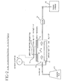
- Fig. 2 Drug delivery in an in vitro model was used to evaluate the performance of the patch containing the hydrogel composition of Example 1.
- the in vitro model is shown schematically in Fig. 2, and is generally known in the art. (W.J. Addicks, G.L. Flynn and N. Weiner, "Validation of a Flow-through Diffusion Cell for use in Transdermal Research", Pharmaceutical Research , vol.4, 1987, pp.337-341).
- an iontophoretic patch 8 as described above, was placed on a skin or membrane 9, such as excised pig skin.
- Excised pig skin can be prepared according to known methods, including those described in Kligman, A.M., et al., Arch.
- the receptor fluid had the following composition: Water 3 liters 1N NaOH 17.5 ml PEG 400 (Carbowax 400 NF, Union Carbide) 70 ml Surfactant (Pluronic P103, BASF P103) 3 ml NaCl 17.54 g Buffer HEPES 7.15 g (N-[2-Hydroxyethyl] piperazine-N'-[2 ethanesulfonic acid]) Sigma Sodium azide 0.306 g
- the receptor fluid 13 in the in vitro cell was removed on an hourly basis via a pump 14, situated outside the in vitro cell 10.
- the fluid was then collected in a fraction collector 15 and the amount of drug delivered was measured by radioactivity detection means, not shown, as a function of time.
- hydrogel compositions in accordance with the claimed invention are capable of iontophoretic drug delivery.
- hydrogel reservoir compositions are possible in accordance with the present invention, and the invention is therefore not limited to those compositions shown in the example.
- suitable polyelectrolytes are known to those skilled in the art, and the present invention is not limited to those specifically mentioned.
Description
- The present invention relates to an iontophoretic patch for the transdermal delivery of drugs, with an improved hydrogel reservoir.
- Administration of medicaments using iontophoresis is known. Simply defined, iontophoresis is the introduction by means of electric current, of ions of soluble salts into the tissues of the body for therapeutic purposes. In presently known iontophoretic devices, at least two electrodes are used. Both of these electrodes are positioned to be in intimate electrical contact with some portion of the skin of the body. One electrode, called the active or donor electrode, is the electrode from which the ionic substance, medicament, drug precursor or drug is delivered into the body by iontophoresis. The other electrode, called the counter or return electrode, serves to close the electrical circuit through the body. In conjunction with the patient's skin contacted by the electrodes, the circuit is completed by connection of the electrodes to a source of electrical energy, e.g., a battery. For example, if the ionic substance to be delivered into the body is positively charged, i.e. a cation, then the anode will be the active electrode and the cathode will serve to complete the circuit. If the ionic substance to be delivered is negatively charged, i.e. an anion, then the cathode will be the active electrode and the anode will be the counter electrode.
- Alternatively, both the anode and cathode may be used to deliver drugs of opposite charge into the body. In such a case, both electrodes are considered to be active or donor electrodes. For example, the anode can deliver a positively charged ionic substance into the body while the cathode can deliver a negatively charged ionic substance into the body.
- It is also known that iontophoretic delivery devices can be used to deliver an uncharged drug or agent into the body. This is accomplished by a process called electroosmosis. Electroosmosis is transdermal flux of a liquid solvent (e.g., the liquid solvent containing the uncharged drug or agent) which is induced by the presence of an electric field imposed across the skin by the donor electrode. As used herein, the terms "iontophoresis" and "iontophoretic" apply equally to electrically powered devices which deliver charged/ionic agents by iontophoresis as well as to electrically powered devices which deliver uncharged/nonionic agents by electroosmosis.
- In the typical iontophoretic patch, a matrix of reservoirs to hold the drug or medicament, or beneficial agent is provided. A reservoir can be of any material adapted to absorb and hold a sufficient quantity of liquid therein in order to permit transport of agent therethrough by iontophoresis. Preferably, a matrix of reservoirs is used, which is composed at least in part of a hydrophilic polymer.
- In order to conduct electrical current the reservoirs must be sufficiently hydrated to allow ions to flow therethrough. In most cases the liquids used to hydrate the matrices of the reservoirs will be water, but other liquids can also be used to activate the matrices of the reservoirs.
- The combination of water soluble polymer and water or liquid results in the reservoir containing a hydrogel. Electrical current is applied to the reservoir by means of a current distributing member. This member can take the form of a metal plate, a foil layer, a screen or a dispersion of particles. Use of sacrificial current distributing members which are oxidized or reduced during drug delivery are preferred. However, such devices produce ions, such as silver ions, which cannot be permitted to be transferred to the skin due to adverse affects. Nor can a significant build-up of ions be permitted because the efficiency of the iontophoresis device may be impeded due to competition with the drug ion.
- Therefore it is necessary for the reservoir also to contain a counter-ion to react with the electrochemically generated ion. However, many drug salts do not possess the proper ion for reacting with the electrochemically generated ion. For example, in some instances, water soluble salts would be produced, which would remain in their ionized state in the reservoir. Therefore, it is important to provide a counter-ion in the reservoir which can effectively eliminate the ion generated by the electrode.
- Since the drug to be delivered is also charged, precautions must be taken to prevent the drug from coming into contact with counter-ions which are incorporated to eliminate the ion generated by the electrode. Methods of accomplishing this are known in the art. A two compartment model is typically used, comprising a drug reservoir which must be isolated from the second reservoir containing the active electrode by a membrane that prevents direct contact between the drug and the ion exchange media.
- Membranes, typically size exclusion membranes, are used to separate the two reservoir compartments. The membrane must be selected to prevent the drug ion from migrating into the reservoir containing the active electrode, and also to prevent the ion exchange means from drifting into the drug reservoir. An example of such a two compartment device is shown in Figure 1. A two compartment reservoir 1, is divided into an
upper reservoir 2 containing anactive electrode 3. The reservoirs are situated in afoam ring 6. The upper reservoir is separated from a lower reservoir 4 by aseparator membrane 5. In this instance the drug is stored in the lower reservoir. The bottom of the lower reservoir is sealed by a release liner 7, which is removed prior to application of the iontophoretic device to a patient. Examples of other two compartment membranes may be found in Haak, U.S. Pat. No. 4,927,408 and Phipps, U.S. Pat. No. 5,084,008. - In Phipps, it is the drug containing reservoir which is equipped with the counter ion. In one embodiment, this is accomplished by constructing an electrode having a conductive, current distributing member; means for coupling the current distributing member to a source of electrical current; a reservoir containing an ionic or ionizable drug; an ion source layer in intimate contact with the current distributing member; and a layer of selectively permeable material applied to the ion source layer which is between the current distributing member and the reservoir. Examples of ion source layers include salt layers, ion exchange resins or chelating agents. Also useful are salts in thin hydrogel material or a substantially dehydrated layer which would absorb a solvent. The selectively permeable material is capable of separating materials by charge and or size. The construction of this device is complex, involving many different layers, thus increasing the cost and time for their manufacture.
- Haak discloses a construction where the drug reservior is in contact with a membrane, including a hydrogel, which is loaded with an ion exchange resin or a chelating agent. However, such a device brings the drug into contact with ion exchange media, such as a membrane or resin, and this can lead to some portion of the drug becoming immobilized. Further, restricting the ion exchange capacity of the device to a thin membrane, rather than a large volume of material, limits its ion exchange capacity.
- Phipps U.S. 5,423,739 discloses a two layer iontophoretic device, wherein the top layer is referred to as the carrier layer and the bottom layer is the skin-contacting layer. The skin contacting layer contains an ionic polymer component. In Phipps, the carrier layer includes the drug or active agent, and few or no mobile ionizable substances. In one embodiment, the mobile ions of the hydrogel in the skin contacting layer have a charge opposite from that of the ionized active agent. This means that the ionized active agent and the polymer backbone have the same charge. The two layers are separated by an impermeable barrier and the device only becomes active when this impermeable barrier is breached. Once the impermeable barrier is broken, the ionized active agent and the mobile counter ions are in direct contact with each other. This contact can lead to unwanted interaction between these two elements and adversely affect drug delivery.
- Phipps also suggests that the relatively small counter ion of the ionomeric component in the skin contacting layer can be selected to interact with the electrochemically generated species at the anode or the cathode. However, this arrangement relies on the mobile counter ions being able to come into contact with the electrochemically generated ions in a very complex matrix system. Due to the complexities of various hydrogel systems, one cannot always be assured that the mobile counter ions will encounter and react with the electrochemically generated ions. Further, the unwanted interactions between the ionized active agent and the mobile counter ion also exist in this arrangement.
- Additionally, Phipps shows examples where the active agent and the ionic polymer backbone are oppositely charged. However, in these instances, the active agent and the ionic polymer are in direct contact with each other in order to convert the active agent to a cationic state.
- Additionally, the reservoirs containing the active electrode have been known to include water-insoluble, cross-linked ion-exchange resins which serve to bind the ion generated during the iontophoretic process. An example of the use of a non-water soluble ion-exchange resin in a iontophoretic patch reservoir is found in Chien, et al., U.S. Pat. No. 5,250,022.
- Systems of this general type are also disclosed in WO 95/09670, which discloses a two-compartment iontophoretic device comprising first and second layers of hydrophilic gel polymer, separated by a membrane. The first layer contains dispersed therein an ion exchange resin.
- EP-A-509122 discloses a single-layer iontophoretic device comprising a single reservoir which can contain polyelectrolyte as a pH buffer.
- Ion-exchange resins, which are included in the hydrogel in the reservoir in the prior art, such as those disclosed in Chien, result in the hydrogel reservoir having a non-uniform consistency. The resins often settle out of the matrix. Very high concentrations of ion exchange resin at the bottom of the reservoir can hinder ion mobility, which can seriously affect the operation of the iontophoretic patch.
- Uniform reservoirs are also difficult to achieve when processing the ion-exchange resins due to the fact that the cross-linked particles behave as a filler, so viscosity increases hyperbolically with particle concentration. The matrix can often become very dough-like in preparation. This results in production difficulties, and consequently increases the cost of the product, due to lengthy production times and a high rejection rate of finished product. The high viscosity also limits formulation possibilities in designing the drug reservoir.
- Ion-exchange membranes, on the other hand, are physical barriers which are not only susceptible to flaws, they can also be damaged, thus potentially greatly diminishing their effectiveness.
- It is therefore an object of this invention to produce a hydrogel reservoir matrix for a two compartment iontophoretic patch which is homogeneous and not susceptible to separation.
- It is another object of this invention to provide a hydrogel reservoir matrix for a two compartment iontophoretic device which can be processed easily, and which does not have an excessive viscosity.
- Yet another object of this invention is a hydrogel reservoir matrix for a two compartment iontophoretic patch which is not dependent on a thin physical barrier for ion exchange.
- Higher ion exchange capacity per unit volume in a hydrogel reservoir matrix for an iontophoretic patch is also a desired object of this invention.
- Increased reliability of the capture of electrochemically generated ions is another feature of the present invention.
- The present invention provides an iontophoretic device as set out in claim 1 and thus solves the problems of the prior art hydrogel matrices by using water soluble polyelectrolytes as a constituent of the hydrogel reservoirs in two compartment iontophoretic patches. These polyelectrolytes are selected to have a fixed counter-ion on the polymer chain which can bind a suitably charged ion (i.e. ion exchange). The most common ion for which such an interaction is useful is the silver ion generated at a silver electrode during iontophoresis. The polyelectrolyte is chosen so that it is miscible with or even soluble with the polymers that make up the hydrogel phase in the hydrogel reservoir. In such a case, the polyelectrolyte becomes dispersed on a very small scale level.
-
- Figure 1 is a diagram of a two-compartment iontophoretic patch.
- Figure 2 is a schematic representation of anodal iontophoretic drug delivery in an in vitro cell.
- Figure 3 is a graph showing the amount of drug delivery as a function of time using the iontophoretic patch of the present invention.
-
- The present invention is directed to an improvement in the hydrogel reservoir of an iontophoretic patch. The improvement resides in the use of a water soluble polyelectrolyte in the reservoir to bind ions generated during electrophoresis. By relying on a polymer to bind these ions in such a complex system, rather than small mobile ions, the dependability of the system is enhanced.
- The reservoir itself must be hydrated. Moreover, the reservoir is in the form of a matrix. Most preferably, the matrix of reservoirs is composed of a matrix-forming material. This matrix forming material is, at least in part, composed of a hydrophilic polymer material. Both natural and synthetic hydrophilic polymers may be used. Suitable hydrophilic polymers include polyvinylpyrrolidones, polyvinyl alcohol, polyethylene oxides such as Polyox® manufactured by Union Carbide Corp.; Carbopol® manufactured by BF Goodrich of Akron, Ohio; blends of polyoxyethylene or polyethylene glycols with polyacrylic acid such as Polyox® blended with Carbopol®, polyacrylamide, Klucel®, cross-linked dextran such as Sephadex (Pharmacia Fine Chemicals, AB, Uppsala, Sweden); Water Lock® (Grain Processing Corp., Muscatine, Iowa) which is a starch-graft-poly(sodium acrylate-co-acrylamide)polymer; cellulose, derivatives such as hydroxyethyl cellulose, hydroxypropylmethylcellulose, low substituted hydroxypropylcellulose, and cross-linked Na-carboxymethylcellulose such as Ac-Di-Sol (FMC Corp., Philadelphia, Pa.); hydrogels such as polyhydroxyethyl methacrylate (National Patent Development Corp.); natural gums, chitosan, pectin, starch, guar gum, locust bean gum, along with blends thereof. Of these, polyvinylpyrrolidones are preferred.
- In order to conduct electrical current, the reservoirs must be sufficiently hydrated to allow ions to flow therethrough. In most cases the liquid used to hydrate the matrices of the reservoirs will be water, but other non-aqueous liquids, can also be used to "hydrate" (i.e., activate) the matrices of the reservoirs. In the typical case where the hydrating liquid is water, the matrices of the reservoirs will be at least partly composed of a hydrophilic material such as a hydrophilic polymer, a cellulose sponge or pad or other water retaining material. Most preferably, the matrices of the reservoirs will be at least partly composed of a hydrophilic polymer of the type described hereinbefore.
- The present invention relies on the use of water soluble polyelectrolytes. The term polyelectrolyte denotes a class of macromolecular compounds, which, when dissolved in a suitable polar solvent, such as water, spontaneously acquire or can be made to acquire a large number of elementary charges distributed along the macromolecular chain. See Concise Encyclopedia of Polymer Science and Engineering, J.I. Kroschwitz (Ed.), 1990, pp.788-93.
- The water soluble polyelectrolytes used in the present invention are selected so that the fixed ion on the polymer chain can bind a suitably charged ion generated by the electode during iontophoresis. The polyelectrolyte is chosen so that it is miscible with or even soluble with the polymers that make up the hydrogel phase in the matrx.
- Another important characteristic of the polyelectrolyte selected is that it must be medically acceptable. For example, a polyelectrolyte with Hg or Ag ions would not be acceptable. Further, the polyelectrolyte must be medical grade, so that no harmful solvents or residual monomers are incorporated into the iontophoretic patch.
- The polymer selected also should not be cross-linked, and should have a molecular weight of about 1,000 or greater. Polyelectrolytes with strongly ionic groups such as sulfonates, carboxylates and phosphates may be used. Examples of polyelectrolytes which are suitable for use in the present invention are the high molecular weight cations dextran carbonates, aminated styrenes, polyvinylimine, polyethyleneimine, poly(vinyl 4-alkylpyridinium), and poly(vinylbenzyltrimethyl ammonium). Suitable high molecular weight anions include polymethacrylates, polystyrene sulfonates, hyaluronate, alginate, dextran sulfonates, acrylamido methyl propane sulfonates ("poly-AMPS"), and sodium polystyrene sulfonate ("NaPSS"). The anionic compounds are preferred, with poly-AMPS and NaPSS being more preferred. The most preferred water soluble polyelectrolyte is NaPSS, which is available under the trademark Kayexalate from Spectrum Chemical Mfg. Corp. This polyelectrolyte is the sodium form of a sulfonated divinylbenzene styrene copolymer.
- Interestingly, use of a macroscopic, cross-linked polyelectrolyte composition with the same chemical identity as NaPSS, results in a hydrogel matrix having the problems noted earlier. More specifically, Amberlite IRP-69 is a pharmaceutical grade cation exchange resin available from Rohm and Haas Company. It is supplied as a dry, fine powder and is derived from a sulfonated copolymer of styrene and divinylbenzene. Combination of 15% of this resin with 15% polyvinylpyrrolidone and 70% water to form a hydrogel matrix for iontophoretic drug delivery presents rheological problems. If the total solids content is above about 35%, the mixture becomes highly viscous and difficult to process. If the amount of PVP is too low, the ion-exchange resin will settle out of the mixture. That means that for some drugs, it is not possible to add enough ion exchange resin without making the reservoir very large. The drug reservoir cannot become too large because that increases the dilution of the drug and tends to decrease the dose efficiency of the patch.
- Additionally, the formulations containing the ion-exchange resin frequently lack sufficient tackiness. Tackiness is an important feature of a hydrogel reservoir because a non-sticky hydrogel can separate from the electrodes and cause failure of the device.
- In contrast, a similar reservoir made using the water soluble NaPSS polyelectrolyte of the present invention is sufficiently tacky to avoid problems of separation. Moreover, the composition is not too viscous, does not separate on standing and is easier to process.
- The amount of polymer or other substance used to form the reservoir matrix can vary, but is typically about 1 to about 50%.
- The amount of water soluble polyelectrolyte contained in the hydrogel matrix reservoir can be from 1-100% of the matrix, with 10-100% being the preferred range.
- The higher range of water soluble polyelectrolyte is suitable in the instance where the polyelectrolyte is capable of forming a gel by itself.
- Any drug capable of iontophoretic delivery may be used in the present invention. For example drugs used in pain management, such as morphine, sufentanil, remifentanil, Ketorolac®, butorphanol, fentanyl, hydromorphone, oxymorphone and buprenorphine are useful in the invention.
- Anti-emetics such as ondansetron, granisetron, and metoclopramide may be used.
- Migraine treatments including dihydroergotamine, 311C naratriptan and sumatriptan may also be used.
- Drugs which may be classified as peptides are also capable of iontophoretic delivery. Examples of such compounds include calcitonin used to treat osteoporosis, octreotide, which is used to counteract the effects of growth hormone and enkephalins, endorphins, and analogs for pain management.
- Other drugs which would be useful in the present invention include, but are not limited to, analgesics, antithrombotics, anticonvulsants, antidepressants, antiinflammatory agents, antiobesity agents and antipsychotics. Other classes of drugs which would find utility in the present invention are known to those familiar with iontophoretic drug delivery.
- The two compartments of the iontophoretic patch can be separated by a number of methods disclosed in the prior art, as previously described. In the present invention, permeable, size exclusion membranes are the preferred means of separating the reservoir containing the active electrode and the drug reservoir. The size exclusion membrane must be capable of preventing drug molecules from diffusing into the reservoir containing the active electrode, and also of preventing ion exchange polyelectrolytes from diffusing down into the drug reservoir, yet permit the passage of small ions necessary for the iontophoretic process to take place. The drug molecules are usually much smaller than the ion exchange polyelectrolyte, and are the limiting factor in membrane selection. As an example of a size exclusion membrane which may be used in the present invention, YCO-5, available from Amicon is suitable. YCO-5 is a membrane consisting of cellulose acetate. Of course, any size exclusion membrane which meets the performance criteria outlined above may be used.
- The iontophoretic delivery device of the present invention is preferably flexible enough to conform to contours of the body. While not limited to any particular size or shape, the device typically is about 5.08 to 7.62 cm (two or three inches) long, about 3.81 cm (one and one-half inches) wide, and has a thickness of approximately 0.64 cm (one-quarter of an inch). The combined skin-contacting areas of electrode assemblies can vary from less than 1 cm2 to greater than 200 cm2. The average device however, will have electrode assemblies with a combined skin-contacting area within the range of about 5 to 50 cm2. As constructed, electrode assemblies are electrically isolated from each other until the device is applied to the human body, whereupon a circuit through the human tissue is completed between the electrode assemblies.
- The beneficial agent or drug, in the case of the donor electrode reservoir and the electrolyte salt in the case of the counter electrode reservoir may be added to the drug reservoir matrix either at the time of manufacture of the device or at the time of use of the device. For example, when the drug or electrolyte is added to the drug-containing reservoir matrix at the time of manufacture of the device, blending of the drug or electrolyte with the drug reservoir matrix components can be accomplished mechanically either by milling, extrusion, or hot-melt mixing. The resulting dry state reservoirs may then be prepared by solvent casting, extrusion or by melt-processing, for example. In addition to the drug and polyelectrolyte, the reservoirs may also contain other conventional materials such as dyes, pigments, inert fillers, and other excipients.
- On the other hand, the reservoirs may be manufactured with no drug or polyelectrolyte. In such a case, the drug and polyelectrolyte can be added to the reservoirs, by adding a solution of the drug and a solution of the polyelectrolyte to the appropriate reservoir matrix and compartment at the time of use.
- Other ingredients such as antimicrobial agents and anti-oxidants may also be beneficially included in the hydrogel reservoir of the present invention.
-
- 15% BASF K90F polyvinylpyrrolidone
- 15% Kayexalate® USP grade Sodium Polystyrene Sulfonate (NaPSS)
- 1% Nipastat Phenonip® (an antimicrobial preservative) 0.09 % NaCl
- Balance water
-
- This formulation was mixed to dissolve the solid components.
- Three compositions with the above formulations were prepared. They were designated A1, A2, and A3.
- The compositions described above were placed into 2 cm2 anode patches, whose construction is described below. After each composition was in place in the upper compartment of the patch, it was irradiated in situ with a high energy electron beam to crosslink the composition. Naturally, the higher the dose of energy applied, the greater the resulting degree of crosslinking.
- Composition A1 received 2.3 mrad of radiation.
Compositions A2 and A3 both received 1 mrad of radiation each. - Subsequently, the patches containing compositions A1, A2 and A3 were evaluated in an in vitro system to determine if the resulting patch was able to meet its intended function.
- The patches were made using a two-compartment model, as shown schematically in Fig. 1. The lower, drug containing reservoir is made using a rigid, open-celled polyethylene, hydrophilic foam, available from Porex Technologies Corp., Fairburn, GA, as part no. 4896. A separator membrane, such as Amicon's YCO-5 with a 500 molecular weight cut-off, is placed on the upper side of the lower reservoir. The bottom of the lower reservoir is sealed with an adhesive liner. The upper reservoir is fabricated using strips of adhesive coated polyethylene foam, such as those available from Avery Dennison, Specialty Tapes Division. A one eighth inch thick foam is used. Die cut holes are made in the foam to permit the introduction of the electrode. Delker Corporation supplies the silver mesh used for the electrode, part number 6AG-10-077.
- The reservoirs can be filled via pipette or by syringe. In the in vitro experiments performed using the above hydrogel formulation, the drug reservoirs contained a proprietary, cationic peptide drug having a molecular weight of about 600 which functions as a growth hormone releasing peptide (GHRP). A composition containing this GHRP was placed in the lower reservoir and was prepared using the following ingredients:
- 1.5 gram peptide drug, radioactively labeled
- .32 gram glacial acetic acid
- 1.5 gram glycerine
- 1.68 gram deionized water
-
- The above ingredients were mixed to yield a formulation having a drug concentration of 100 mg/ml. The acetic acid is present to ionize the peptide.
- Drug delivery in an in vitro model was used to evaluate the performance of the patch containing the hydrogel composition of Example 1. The in vitro model is shown schematically in Fig. 2, and is generally known in the art. (W.J. Addicks, G.L. Flynn and N. Weiner, "Validation of a Flow-through Diffusion Cell for use in Transdermal Research", Pharmaceutical Research, vol.4, 1987, pp.337-341). According to Figure 2, an
iontophoretic patch 8, as described above, was placed on a skin ormembrane 9, such as excised pig skin. Excised pig skin can be prepared according to known methods, including those described in Kligman, A.M., et al., Arch. Dermatol., 88:702-05 (1963). The skin was positioned over an in vitrocell 10, containing acathode 11. A constant DC current was supplied to theanode 12 andcathode 11.Receptor fluid 13 was supplied to the in vitrocell 10. The receptor fluid had the following composition:Water 3 liters 1N NaOH 17.5 ml PEG 400
(Carbowax 400 NF, Union Carbide)70 ml Surfactant
(Pluronic P103, BASF P103)3 ml NaCl 17.54 g Buffer HEPES 7.15 g (N-[2-Hydroxyethyl] piperazine-N'-[2 ethanesulfonic acid]) Sigma Sodium azide 0.306 g - The above ingredients were mixed to obtain a solution for use as a receptor fluid with a pH of 7.4.
- After the current was turned on, and the drug began to be transported across the
membrane 9, thereceptor fluid 13 in the in vitro cell was removed on an hourly basis via apump 14, situated outside the in vitrocell 10. The fluid was then collected in afraction collector 15 and the amount of drug delivered was measured by radioactivity detection means, not shown, as a function of time. - Using the hydrogel formulations of the present invention, A1, A2, and A3, as previously described, a constant current of 250 microamps per square centimeter was applied for 24 hours. The in vitro delivery of the drug was then measured as flux, in micrograms per hour as a function of time. The results are shown in Figure 3. These results demonstrate that hydrogel compositions in accordance with the claimed invention are capable of iontophoretic drug delivery.
- It will be understood by one of ordinary skill in the art that many possible hydrogel reservoir compositions are possible in accordance with the present invention, and the invention is therefore not limited to those compositions shown in the example. Similarly, a wide variety of suitable polyelectrolytes are known to those skilled in the art, and the present invention is not limited to those specifically mentioned.
Claims (14)
- An iontophoretic device having two compartments which are situated on top of each other and are separated by a permeable means, and wherein a hydrogel reservoir containing an active sacrificial electrode is situated in one of said two compartments and comprises a water soluble polyelectrolyte and a fluid.
- The device according to claim 1 in which the hydrogel reservoir further comprises a matrix-forming material in addition to the water soluble polyelectrolyte and fluid.
- The device according to claim 2 wherein the matrix-forming material is a hydrophilic polymer.
- The device according to claim 3 wherein the hydrophilic polymer is a polyvinylpyrrolidone.
- The device according to any preceding claim wherein the water soluble polyelectrolyte is sodium polystyrene sulfonate.
- The device according to any of claims 1 to 4 wherein the water soluble polyelectrolyte includes one or more ions from the group consisting of sulfonates, carboxylates and phosphates.
- A device according to claim 1 wherein the fluid is water.
- A device according to claim 3 wherein the fluid is water, the hydrophilic polymer is polyvinylpyrrolidone and the water soluble polyelectrolyte is water soluble sodium polystyrene sulfonate.
- A device according to claim 8 in which the hydrogel reservoir contains about 15% polyvinylpyrrolidone and about 15% sodium polystyrene sulfonate.
- A device according to any preceding claim wherein the active electrode is an anode.
- A device according to any preceding claim wherein the active electrode is a cathode.
- The device according to claim 10 wherein the water soluble polyelectrolyte includes one or more high molecular weight anions from the group consisting of polymethacrylates, polystyrene sulfonates, polyhyaltaronate, polyalginate, dextran sulfonates, acrylamidomethyl propane sulfonates, polycarboxylates and polyphosphates.
- The device according to claim 11 wherein the water soluble polyelectrolyte includes one or more high molecular weight cations from the group consisting of aminated styrenes, polyvinylimines, polyethyleneimine, poly(vinyl 4 alkylpyridinium) and poly(vinylbenzyltrimethyl ammonium).
- The device according to any preceding claim wherein the compartment that does not contain the active electrode, contains a drug which is remifentanil.
Applications Claiming Priority (2)
| Application Number | Priority Date | Filing Date | Title |
|---|---|---|---|
| US941746 | 1992-09-08 | ||
| US08/941,746 US5882677A (en) | 1997-09-30 | 1997-09-30 | Iontophoretic patch with hydrogel reservoir |
Publications (3)
| Publication Number | Publication Date |
|---|---|
| EP0904779A2 EP0904779A2 (en) | 1999-03-31 |
| EP0904779A3 EP0904779A3 (en) | 2000-01-26 |
| EP0904779B1 true EP0904779B1 (en) | 2004-12-15 |
Family
ID=25477007
Family Applications (1)
| Application Number | Title | Priority Date | Filing Date |
|---|---|---|---|
| EP98307962A Expired - Lifetime EP0904779B1 (en) | 1997-09-30 | 1998-09-30 | Iontophoretic patch with hydrogel reservoir |
Country Status (5)
| Country | Link |
|---|---|
| US (1) | US5882677A (en) |
| EP (1) | EP0904779B1 (en) |
| JP (1) | JPH11155962A (en) |
| CA (1) | CA2249039C (en) |
| DE (1) | DE69828126T2 (en) |
Cited By (1)
| Publication number | Priority date | Publication date | Assignee | Title |
|---|---|---|---|---|
| US8062783B2 (en) | 2006-12-01 | 2011-11-22 | Tti Ellebeau, Inc. | Systems, devices, and methods for powering and/or controlling devices, for instance transdermal delivery devices |
Families Citing this family (51)
| Publication number | Priority date | Publication date | Assignee | Title |
|---|---|---|---|---|
| US5814094A (en) * | 1996-03-28 | 1998-09-29 | Becker; Robert O. | Iontopheretic system for stimulation of tissue healing and regeneration |
| US6861570B1 (en) * | 1997-09-22 | 2005-03-01 | A. Bart Flick | Multilayer conductive appliance having wound healing and analgesic properties |
| US7214847B1 (en) * | 1997-09-22 | 2007-05-08 | Argentum Medical, L.L.C. | Multilayer conductive appliance having wound healing and analgesic properties |
| US8455710B2 (en) * | 1997-09-22 | 2013-06-04 | Argentum Medical, Llc | Conductive wound dressings and methods of use |
| US8801681B2 (en) * | 1995-09-05 | 2014-08-12 | Argentum Medical, Llc | Medical device |
| US6119036A (en) | 1997-03-26 | 2000-09-12 | The Board Of Regents Of The University Of Oklahoma | Iontophoretic transdermal delivery device |
| US6858018B1 (en) * | 1998-09-28 | 2005-02-22 | Vyteris, Inc. | Iontophoretic devices |
| US6835184B1 (en) | 1999-09-24 | 2004-12-28 | Becton, Dickinson And Company | Method and device for abrading skin |
| US6496727B1 (en) * | 2000-05-31 | 2002-12-17 | Becton, Dickinson And Company | Medicament-loaded transdermal reservoir and method for its formation |
| US6629968B1 (en) * | 2000-06-30 | 2003-10-07 | Vyteris, Inc. | Shelf storage stable iontophoresis reservoir-electrode and iontophoretic system incorporating the reservoir-electrode |
| US6553255B1 (en) * | 2000-10-27 | 2003-04-22 | Aciont Inc. | Use of background electrolytes to minimize flux variability during iontophoresis |
| US20030065285A1 (en) * | 2001-07-23 | 2003-04-03 | Higuchi William I. | Method and apparatus for increasing flux during reverse iontophoresis |
| US20030130314A1 (en) * | 2001-12-17 | 2003-07-10 | Pascal Druzgala | Analgesic delivery systems and methods of use |
| DE10246625A1 (en) * | 2002-10-07 | 2004-04-15 | Basf Ag | Destruction of microorganisms in aqueous systems, involves addition of a water-soluble or -dispersible styrene sulfonic acid (co) polymer as biocide |
| EP1599187A4 (en) * | 2002-11-26 | 2007-08-08 | Univ Maryland | Aqueous sustained-release drug delivery system for highly water-soluble electrolytic drugs |
| JP2006526454A (en) * | 2003-06-02 | 2006-11-24 | パワー ペーパー リミティド | Kit, apparatus and method for controlled delivery of oxidant into skin |
| EP1633332A1 (en) * | 2003-06-11 | 2006-03-15 | The Procter & Gamble Company | Preparation-at-use device comprising pre-formed hydrogel product |
| US7470266B2 (en) * | 2003-09-16 | 2008-12-30 | I-Flow Corporation | Fluid medication delivery device |
| WO2006055729A1 (en) * | 2004-11-16 | 2006-05-26 | Transcutaneous Technologies Inc. | Iontophoretic device and method for administering immune response-enhancing agents and compositions |
| AU2005312736A1 (en) * | 2004-12-09 | 2006-06-15 | Tti Ellebeau, Inc. | Ion-tophoretic apparatus |
| JP2006296511A (en) * | 2005-04-15 | 2006-11-02 | Transcutaneous Technologies Inc | External preparation, method for applying external preparation, iontophoresis device, and transdermal patch |
| JPWO2007010900A1 (en) * | 2005-07-15 | 2009-01-29 | Tti・エルビュー株式会社 | Patch for percutaneous absorption with ion position display function and iontophoresis device |
| WO2007026672A1 (en) * | 2005-08-29 | 2007-03-08 | Transcu Ltd. | General-purpose electrolyte composition for iontophoresis |
| RU2008114830A (en) * | 2005-09-16 | 2009-10-27 | ТиТиАй ЭЛЛЕБО, ИНК. (JP) | CATHETER TYPE IONTOPHORESIS DEVICE |
| JP2009509677A (en) * | 2005-09-30 | 2009-03-12 | Tti・エルビュー株式会社 | Iontophoretic delivery of vesicle encapsulated active substances |
| WO2007041118A1 (en) * | 2005-09-30 | 2007-04-12 | Tti Ellebeau, Inc. | Iontophoretic device and method of delivery of active agents to biological interface |
| KR20080066712A (en) * | 2005-09-30 | 2008-07-16 | 티티아이 엘뷰 가부시키가이샤 | Functionalized microneedles transdermal drug delivery systems, devices, and methods |
| WO2007041543A2 (en) * | 2005-09-30 | 2007-04-12 | Tti Ellebeau, Inc. | Iontophoresis device to deliver multiple active agents to biological interfaces |
| US20070135754A1 (en) * | 2005-09-30 | 2007-06-14 | Hidero Akiyama | Electrode assembly for iontophoresis for administering active agent enclosed in nanoparticle and iontophoresis device using the same |
| WO2007038555A1 (en) * | 2005-09-30 | 2007-04-05 | Tti Ellebeau, Inc. | Iontophoretic device and method of delivery of active agents to biological interface |
| US20070078375A1 (en) * | 2005-09-30 | 2007-04-05 | Transcutaneous Technologies Inc. | Iontophoretic delivery of active agents conjugated to nanoparticles |
| WO2007079116A1 (en) * | 2005-12-28 | 2007-07-12 | Tti Ellebeau, Inc. | Electroosmotic pump apparatus and method to deliver active agents to biological interfaces |
| EP1965856A2 (en) * | 2005-12-30 | 2008-09-10 | Tti Ellebeau, Inc. | Iontophoretic systems, devices, and methods of delivery of active agents to biological interface |
| WO2007123707A1 (en) * | 2006-03-30 | 2007-11-01 | Tti Ellebeau, Inc. | Controlled release membrane and methods of use |
| JP5580042B2 (en) * | 2006-04-13 | 2014-08-27 | ヌパス インコーポレイテッド | Transdermal method and system for delivery of anti-migraine compounds |
| EP2029218B1 (en) * | 2006-06-15 | 2019-08-14 | PolyPharma Pty Ltd | A delivery system |
| EP2034976A2 (en) * | 2006-07-05 | 2009-03-18 | Tti Ellebeau, Inc. | Delivery device having self-assembling dendritic polymers and method of use thereof |
| US20080193514A1 (en) * | 2006-11-02 | 2008-08-14 | Transcu Ltd. | Compostions and methods for iontophoresis delivery of active ingredients through hair follicles |
| WO2008087803A1 (en) * | 2007-01-16 | 2008-07-24 | Hokkaido University | Liposome preparation for iontophoresis having antioxidant component encapsulated therein |
| EP2157970A1 (en) * | 2007-05-18 | 2010-03-03 | Tti Ellebeau, Inc. | Transdermal delivery devices assuring an improved release of an active principle through a biological interface |
| JP2010187707A (en) * | 2007-06-12 | 2010-09-02 | Hokkaido Univ | Liposome preparation for iontophoresis comprising insulin encapsulated therein |
| US8280481B2 (en) | 2007-11-02 | 2012-10-02 | Tyco Healthcare Group Lp | Electrodes possessing pH indicator |
| US8366600B2 (en) * | 2008-06-19 | 2013-02-05 | Nupathe Inc. | Polyamine enhanced formulations for triptan compound iontophoresis |
| EP2154551A1 (en) | 2008-08-12 | 2010-02-17 | Geolab S.a.s. | Method for recording changes in a hydrocarbon deposit |
| BRPI0918060A2 (en) * | 2008-09-10 | 2015-12-01 | Transcu Ltd | apparatus and method of dispensing hpc viscous liquids on porous substrates, for example, continuous tissue based process. |
| WO2011002776A1 (en) * | 2009-06-29 | 2011-01-06 | Nitric Biotherapeutics, Inc. | Pharmaceutical formulations for iontophoretic delivery of an immunomodulator |
| CN102573489A (en) | 2009-08-10 | 2012-07-11 | 纽帕特公司 | Methods for iontophoretically treating nausea and migraine |
| WO2011046927A1 (en) * | 2009-10-13 | 2011-04-21 | Nupathe,Inc. | Transdermal methods and systems for the delivery of rizatriptan |
| US8747383B2 (en) * | 2009-12-18 | 2014-06-10 | University Medical Pharmaceuticals Corp. | Process and system for iontophoretic wrinkle reduction |
| ES2885062T3 (en) * | 2017-06-28 | 2021-12-13 | Fundacion Tecnalia Res & Innovation | Device for controlled and monitored transdermal administration of active ingredients and use thereof |
| US20220062603A1 (en) * | 2020-08-26 | 2022-03-03 | Babak Ghalili | Cannabinoid and menthol transdermal delivery systems and methods |
Family Cites Families (9)
| Publication number | Priority date | Publication date | Assignee | Title |
|---|---|---|---|---|
| US3987163A (en) * | 1973-07-27 | 1976-10-19 | Burton, Parsons And Company, Inc. | Polystyrene sulfonate containing opthalmic solutions |
| US5250022A (en) * | 1990-09-25 | 1993-10-05 | Rutgers, The State University Of New Jersey | Iontotherapeutic devices, reservoir electrode devices therefore, process and unit dose |
| US4927408A (en) * | 1988-10-03 | 1990-05-22 | Alza Corporation | Electrotransport transdermal system |
| EP0429842B1 (en) * | 1989-10-27 | 1996-08-28 | Korea Research Institute Of Chemical Technology | Device for the transdermal administration of protein or peptide drug |
| US5084008A (en) * | 1989-12-22 | 1992-01-28 | Medtronic, Inc. | Iontophoresis electrode |
| US5362308A (en) * | 1990-09-25 | 1994-11-08 | Rutgers, The State University Of New Jersey | Disposable dosage unit for iontophoresis-facilitated transdermal delivery, related devices and processes |
| US5203768A (en) * | 1991-07-24 | 1993-04-20 | Alza Corporation | Transdermal delivery device |
| US5871460A (en) * | 1994-04-08 | 1999-02-16 | Alza Corporation | Electrotransport system with ion exchange material providing enhanced drug delivery |
| WO1998008492A1 (en) * | 1996-08-29 | 1998-03-05 | Novo Nordisk A/S | Transdermal delivery of peptides |
-
1997
- 1997-09-30 US US08/941,746 patent/US5882677A/en not_active Expired - Lifetime
-
1998
- 1998-09-29 CA CA002249039A patent/CA2249039C/en not_active Expired - Fee Related
- 1998-09-30 DE DE69828126T patent/DE69828126T2/en not_active Expired - Lifetime
- 1998-09-30 JP JP10278646A patent/JPH11155962A/en active Pending
- 1998-09-30 EP EP98307962A patent/EP0904779B1/en not_active Expired - Lifetime
Cited By (1)
| Publication number | Priority date | Publication date | Assignee | Title |
|---|---|---|---|---|
| US8062783B2 (en) | 2006-12-01 | 2011-11-22 | Tti Ellebeau, Inc. | Systems, devices, and methods for powering and/or controlling devices, for instance transdermal delivery devices |
Also Published As
| Publication number | Publication date |
|---|---|
| CA2249039A1 (en) | 1999-03-30 |
| EP0904779A3 (en) | 2000-01-26 |
| US5882677A (en) | 1999-03-16 |
| DE69828126D1 (en) | 2005-01-20 |
| DE69828126T2 (en) | 2005-11-03 |
| EP0904779A2 (en) | 1999-03-31 |
| JPH11155962A (en) | 1999-06-15 |
| CA2249039C (en) | 2002-04-02 |
Similar Documents
| Publication | Publication Date | Title |
|---|---|---|
| EP0904779B1 (en) | Iontophoretic patch with hydrogel reservoir | |
| US6289242B1 (en) | Electrotransport system with ion exchange material competitive ion capture | |
| JP3549540B2 (en) | Reducing skin irritation during electrotransport administration | |
| JP3638805B2 (en) | Control membrane for electrotransport drug administration | |
| EP0754078B1 (en) | Electrotransport system with enhanced drug delivery | |
| US6635045B2 (en) | Electrodes and method for manufacturing electrodes for electrically assisted drug delivery | |
| KR100584630B1 (en) | Layered rate controlling membranes for use in an electrotransport device | |
| EP0596036B1 (en) | Transdermal delivery device | |
| EP0555375B1 (en) | Iontophoretic drug delivery electrode and method of hydrating the same | |
| EP0521988B1 (en) | Device for iontophoretic drug delivery | |
| US6350259B1 (en) | Selected drug delivery profiles using competing ions | |
| JPH05507017A (en) | Iontophoresis delivery device | |
| JPH09511662A (en) | Electrotransport device with improved cathode electrode assembly | |
| US20060211980A1 (en) | Transdermal electrotransport drug delivery systems with reduced abuse potential | |
| JP2001506263A (en) | Polymer foam storage tanks for electrotransport and emission devices | |
| EP0457849B1 (en) | Electrotransport adhesive | |
| JP3996203B2 (en) | Electrotransport drug supply and storage system with inert filler. | |
| WO1997012644A1 (en) | Improved iontophoretic reservoir apparatus | |
| JP2905980B2 (en) | Iontophoresis electrode | |
| WO2008140453A1 (en) | Iontophoretic devices for drug delivery |
Legal Events
| Date | Code | Title | Description |
|---|---|---|---|
| PUAI | Public reference made under article 153(3) epc to a published international application that has entered the european phase |
Free format text: ORIGINAL CODE: 0009012 |
|
| AK | Designated contracting states |
Kind code of ref document: A2 Designated state(s): DE FR GB |
|
| AX | Request for extension of the european patent |
Free format text: AL;LT;LV;MK;RO;SI |
|
| PUAL | Search report despatched |
Free format text: ORIGINAL CODE: 0009013 |
|
| AK | Designated contracting states |
Kind code of ref document: A3 Designated state(s): AT BE CH CY DE DK ES FI FR GB GR IE IT LI LU MC NL PT SE |
|
| AX | Request for extension of the european patent |
Free format text: AL;LT;LV;MK;RO;SI |
|
| 17P | Request for examination filed |
Effective date: 20000720 |
|
| AKX | Designation fees paid |
Free format text: DE FR GB |
|
| RAP1 | Party data changed (applicant data changed or rights of an application transferred) |
Owner name: VYTERIS, INC. |
|
| 17Q | First examination report despatched |
Effective date: 20020418 |
|
| GRAP | Despatch of communication of intention to grant a patent |
Free format text: ORIGINAL CODE: EPIDOSNIGR1 |
|
| GRAS | Grant fee paid |
Free format text: ORIGINAL CODE: EPIDOSNIGR3 |
|
| GRAA | (expected) grant |
Free format text: ORIGINAL CODE: 0009210 |
|
| AK | Designated contracting states |
Kind code of ref document: B1 Designated state(s): DE FR GB |
|
| REG | Reference to a national code |
Ref country code: GB Ref legal event code: FG4D |
|
| REF | Corresponds to: |
Ref document number: 69828126 Country of ref document: DE Date of ref document: 20050120 Kind code of ref document: P Owner name: CONCH INTERNATIONAL METHANE LIMITED |
|
| PLBE | No opposition filed within time limit |
Free format text: ORIGINAL CODE: 0009261 |
|
| STAA | Information on the status of an ep patent application or granted ep patent |
Free format text: STATUS: NO OPPOSITION FILED WITHIN TIME LIMIT |
|
| ET | Fr: translation filed | ||
| 26N | No opposition filed |
Effective date: 20050916 |
|
| PGFP | Annual fee paid to national office [announced via postgrant information from national office to epo] |
Ref country code: GB Payment date: 20100325 Year of fee payment: 12 |
|
| PGFP | Annual fee paid to national office [announced via postgrant information from national office to epo] |
Ref country code: FR Payment date: 20100416 Year of fee payment: 12 |
|
| PGFP | Annual fee paid to national office [announced via postgrant information from national office to epo] |
Ref country code: DE Payment date: 20100331 Year of fee payment: 12 |
|
| GBPC | Gb: european patent ceased through non-payment of renewal fee |
Effective date: 20100930 |
|
| REG | Reference to a national code |
Ref country code: FR Ref legal event code: ST Effective date: 20110531 |
|
| REG | Reference to a national code |
Ref country code: DE Ref legal event code: R119 Ref document number: 69828126 Country of ref document: DE Effective date: 20110401 |
|
| PG25 | Lapsed in a contracting state [announced via postgrant information from national office to epo] |
Ref country code: FR Free format text: LAPSE BECAUSE OF NON-PAYMENT OF DUE FEES Effective date: 20100930 Ref country code: DE Free format text: LAPSE BECAUSE OF NON-PAYMENT OF DUE FEES Effective date: 20110401 |
|
| PG25 | Lapsed in a contracting state [announced via postgrant information from national office to epo] |
Ref country code: GB Free format text: LAPSE BECAUSE OF NON-PAYMENT OF DUE FEES Effective date: 20100930 |