EP0903113A2 - Fixed-angle screw connection for bone plates - Google Patents
Fixed-angle screw connection for bone plates Download PDFInfo
- Publication number
- EP0903113A2 EP0903113A2 EP98115861A EP98115861A EP0903113A2 EP 0903113 A2 EP0903113 A2 EP 0903113A2 EP 98115861 A EP98115861 A EP 98115861A EP 98115861 A EP98115861 A EP 98115861A EP 0903113 A2 EP0903113 A2 EP 0903113A2
- Authority
- EP
- European Patent Office
- Prior art keywords
- screw
- bone
- head
- cylindrical sections
- screw connection
- Prior art date
- Legal status (The legal status is an assumption and is not a legal conclusion. Google has not performed a legal analysis and makes no representation as to the accuracy of the status listed.)
- Withdrawn
Links
Images
Classifications
-
- A—HUMAN NECESSITIES
- A61—MEDICAL OR VETERINARY SCIENCE; HYGIENE
- A61B—DIAGNOSIS; SURGERY; IDENTIFICATION
- A61B17/00—Surgical instruments, devices or methods, e.g. tourniquets
- A61B17/56—Surgical instruments or methods for treatment of bones or joints; Devices specially adapted therefor
- A61B17/58—Surgical instruments or methods for treatment of bones or joints; Devices specially adapted therefor for osteosynthesis, e.g. bone plates, screws, setting implements or the like
- A61B17/68—Internal fixation devices, including fasteners and spinal fixators, even if a part thereof projects from the skin
- A61B17/80—Cortical plates, i.e. bone plates; Instruments for holding or positioning cortical plates, or for compressing bones attached to cortical plates
- A61B17/8033—Cortical plates, i.e. bone plates; Instruments for holding or positioning cortical plates, or for compressing bones attached to cortical plates having indirect contact with screw heads, or having contact with screw heads maintained with the aid of additional components, e.g. nuts, wedges or head covers
- A61B17/8042—Cortical plates, i.e. bone plates; Instruments for holding or positioning cortical plates, or for compressing bones attached to cortical plates having indirect contact with screw heads, or having contact with screw heads maintained with the aid of additional components, e.g. nuts, wedges or head covers the additional component being a cover over the screw head
-
- A—HUMAN NECESSITIES
- A61—MEDICAL OR VETERINARY SCIENCE; HYGIENE
- A61B—DIAGNOSIS; SURGERY; IDENTIFICATION
- A61B17/00—Surgical instruments, devices or methods, e.g. tourniquets
- A61B17/56—Surgical instruments or methods for treatment of bones or joints; Devices specially adapted therefor
- A61B17/58—Surgical instruments or methods for treatment of bones or joints; Devices specially adapted therefor for osteosynthesis, e.g. bone plates, screws, setting implements or the like
- A61B17/68—Internal fixation devices, including fasteners and spinal fixators, even if a part thereof projects from the skin
- A61B17/80—Cortical plates, i.e. bone plates; Instruments for holding or positioning cortical plates, or for compressing bones attached to cortical plates
- A61B17/8052—Cortical plates, i.e. bone plates; Instruments for holding or positioning cortical plates, or for compressing bones attached to cortical plates immobilised relative to screws by interlocking form of the heads and plate holes, e.g. conical or threaded
Definitions
- the invention relates to an angle-stable screw connection for Bone plates on the bone, with at least one bone screw is passed through a screw block of the bone plate and one locking screw securing the head of the bone screw against the bone plate is provided.
- bone plates are e.g. made of metal used as temporary or permanent implants.
- the bone plates are fixed to the bone with bone screws and thus enable immediate internal fixation for various joint fractures of the individual fragments. This makes the individual stable Fracture fragments given during bone healing. Due to the stable fixation of the joint surfaces, a plaster-free one Follow-up treatment with early mobilization of the joint possible.
- the screw hole of the bone plate usually has one large drop on and the head usually has one on the contact surface spherical shape. This allows the bone screw inside a certain angular range deviating from the vertical to the Surface of the bone plate.
- US 5 364 399 A1 shows rounded screw heads in trough-shaped Reductions. This does not result in the required angular stability achievable, even if here the locking screw directly on the Screw heads presses.
- the pressure surface of the locking screw is in disadvantageously level, making it easy to loosen comes and dimensional tolerances are poorly balanced.
- EP 599 640 A1 discloses spherical screw holes, which are generally not suitable for angle-stable connections and this problem is not addressed in the document either.
- the known constructions have the disadvantage, among other things that some fragments form fragments together with the or move the bone screw within the permitted angle can. This is especially the case when the bone screws loosen by early mobilization or by porotic bones loosen. The consequences are permanent misalignments of the adjacent ones Articular surfaces after the fracture has healed. If in surgery, e.g. Spine surgery, locking screws are known, then there is no angular stabilization of the bone screws.
- the present invention is characterized in that the screw hole and the head of the bone screw is form-fitting are, the head of the bone screw two cylindrical sections has different diameters, and the screw hole has two matching cylindrical sections.
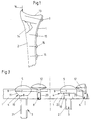
- Fig. 1 shows schematically the view of a bone with a fracture and a screwed on bone plate.
- Fig. 2 shows the supervision a bone plate according to the invention and Figure 3 schematically one Cut along line A-B with inserted screws.
- the bone 2 below the socket 13 shows a fracture zone 14.
- the bone screws 3 and 15 on the bone screwed bone plate 1 the bone for healing stabilized.
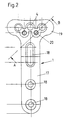
- FIG. 2 shows a plan view of the bone plate according to the invention, which has an outer shape, as for such bone plates is known.
- the shaft 17 has screw holes 18 of the known type on.
- the screw holes in the T-piece 19, however, are specially designed.
- There are (here for example) three screw holes 4 for the Bone screws 3 are provided and offset to these screw holes threaded holes 20 are provided between the screw holes 4.
- the Figure 3 shows the section along the line A-B in Figure 2 with inserted or screwed in bone and locking screws in two Variants.
- the head 5 of the bone screw 3 has two cylindrical sections 7, 8 on that have different diameters and these sections correspond to two matching cylindrical sections 9, 10 of the Screw hole 4.
- the transition between the two cylindrical sections is through both the head 5 and the screw hole 4 formed a frusto-conical (conical) section 11, as in the left variant. In the variant shown on the right the transition is gradual at 22.
- a locking screw 6 is provided.
- the locking screw 6 overlaps with her head 12 the head 5 of the bone screw 3 and secures the bone screw against loosening.
- the bone plate shown is only an example.
- the shape and Bending is to be adapted to the respective bones.
- everyone can Screw connections according to the invention can be provided with stable angles.
- the Screw holes can also be arranged at an angle that is different of 90 °, so that an oblique angular position is fixed.
- Both the bone screws and the locking screws are advantageous spherical at the top and preferably have the same hexagon socket for Allen keys.
- the underside of the locking screws is preferred, either crowned (spherical) or conical to the head of the bone screw to have a good circulation.
Abstract
Description
Die Erfindung betrifft eine winkelstabile Schraubenverbindung für Knochenplatten am Knochen, wobei wenigstens eine Knochenschraube durch ein Schraublock der Knochenplatte hindurchgeführt ist und eine den Kopf der Knochenschraube gegen die Knochenplatte sichernde Sicherungsschraube vorgesehen ist.The invention relates to an angle-stable screw connection for Bone plates on the bone, with at least one bone screw is passed through a screw block of the bone plate and one locking screw securing the head of the bone screw against the bone plate is provided.
Im Bereich der Unfallchirurgie werden Knochenplatten z.B. aus Metall als temporäre oder permanente Implantate verwendet. Die Knochenplatten werden mit Knochenschrauben am Knochen fixiert und ermöglichen so bei verschiedenen Gelenksfrakturen eine sofortige interne Fixierung der einzelnen Fragmente. Dadurch ist eine stabile Lage der einzelnen Frakturfragmente während des Wiederverheilens des Knochens gegeben. Durch die stabile Fixation der Gelenksflächen ist eine gipsfreie Nachbehandlung mit frühzeitiger Mobilisierung des Gelenkes möglich.In the area of accident surgery, bone plates are e.g. made of metal used as temporary or permanent implants. The bone plates are fixed to the bone with bone screws and thus enable immediate internal fixation for various joint fractures of the individual fragments. This makes the individual stable Fracture fragments given during bone healing. Due to the stable fixation of the joint surfaces, a plaster-free one Follow-up treatment with early mobilization of the joint possible.
Bekannte derartige Knochenplatten und die zugehörigen Knochenschrauben sind in ihrer Winkelstellung zueinander nicht fixiert. Das Schraubloch der Knochenplatte weist üblicherweise eine große Senkung auf und der Kopf hat an der Kontaktfläche zumeist eine kugelflächenförmige Form. Dadurch kann die Knochenschraube innerhalb eines gewissen Winkelbereiches abweichend von der Vertikale auf die Oberfläche der Knochenplatte eingeschraubt werden.Known such bone plates and the associated Bone screws are not fixed in their angular position to each other. The screw hole of the bone plate usually has one large drop on and the head usually has one on the contact surface spherical shape. This allows the bone screw inside a certain angular range deviating from the vertical to the Surface of the bone plate.
Die DE 33 01 298 A1 offenbart nebeneinanderliegende konische Schraublöcher, in denen konisch ausgebildete Köpfe der Knochenschrauben versenkt werden. Die Köpfe werden durch eine elastische Scheibe, die von einer Schraube fixiert ist, gesichert. Diese Anordnung bietet jedoch keine tatsächlich winkelstabile Verbindung zwischen Knochenschraube und Knochenplatte, da die konischen Schraublöcher bei der geringen Dicke der Knochenplatte zu wenig Halt verleihen. Eine elastische Scheibe ist zum Fixieren der Knochenschrauben nicht geeignet.DE 33 01 298 A1 discloses adjacent conical screw holes, in which conical heads of the bone screws be sunk. The heads are covered by an elastic washer is secured by a screw. However, this arrangement offers no actually angle-stable connection between the bone screw and bone plate, since the conical screw holes at the Giving too little hold to the small thickness of the bone plate. An elastic The washer is not suitable for fixing the bone screws.
Die US 5 364 399 A1 zeigt abgerundete Schraubenköpfe in muldenförmigen Senkungen. Die erforderliche Winkelstabilität ist dadurch nicht erzielbar, auch wenn hier die Sicherungsschraube direkt auf die Schraubenköpfe drückt. Die Druckfläche der Sicherungsschraube ist in nachteiliger Weise eben ausgebildet, wodurch es leicht zu einer Lockerung kommt und Maßtoleranzen schlecht ausgeglichen werden.US 5 364 399 A1 shows rounded screw heads in trough-shaped Reductions. This does not result in the required angular stability achievable, even if here the locking screw directly on the Screw heads presses. The pressure surface of the locking screw is in disadvantageously level, making it easy to loosen comes and dimensional tolerances are poorly balanced.
Die EP 599 640 A1 offenbart sphärisch ausgebildete Schraubenlöcher, die grundsätzlich nicht für winkelstabile Verbindungen geeignet sind und dieses Problem ist in der Druckschrift auch nicht angesprochen.EP 599 640 A1 discloses spherical screw holes, which are generally not suitable for angle-stable connections and this problem is not addressed in the document either.
Die bekannten Konstruktionen bringen unter anderem den Nachteil mit sich, daß bei manchen Frakturformen sich Fragmente gemeinsam mit der oder den Knochenschrauben innerhalb der zugelassenen Verwinkelung bewegen können. Dies insbesondere dann, wenn sich die Knochenschrauben durch die frühe Mobilisierung lockern oder durch porotische Knochen lockern. Die Folgen sind bleibende Fehlstellungen der angrenzenden Gelenksflächen nach vollendeter Bruchheilung. Wenn in der Chirurgie, z.B. Wirbelsäulenchirurgie, Sicherungsschrauben bekannt sind, dann erfolgt durch diese keine Winkelstabilisierung der Knochenschrauben.The known constructions have the disadvantage, among other things that some fragments form fragments together with the or move the bone screw within the permitted angle can. This is especially the case when the bone screws loosen by early mobilization or by porotic bones loosen. The consequences are permanent misalignments of the adjacent ones Articular surfaces after the fracture has healed. If in surgery, e.g. Spine surgery, locking screws are known, then there is no angular stabilization of the bone screws.
Die vorliegende Erfindung ist dadurch gekennzeichnet, daß das Schraubloch und der Kopf der Knochenschraube formschlüssig ausgebildet sind, wobei der Kopf der Knochenschraube zwei zylindrische Abschnitte aufweist, die verschiedene Durchmesser haben, und das Schraubloch zwei passende zylindrische Abschnitte aufweist.The present invention is characterized in that the screw hole and the head of the bone screw is form-fitting are, the head of the bone screw two cylindrical sections has different diameters, and the screw hole has two matching cylindrical sections.
Weitere vorteilhafte Merkmale der Erfindung sind den Patentansprüchen, der nachfolgenden Beschreibung und den Zeichnungen zu entnehmen. Further advantageous features of the invention are the patent claims, the following description and the drawings remove.
Im nachfolgenden wird die Erfindung anhand der Fig.1 bis 3 näher erläutert.The invention is explained in more detail below with reference to FIGS. 1 to 3.
Fig.1 zeigt schematisch die Ansicht eines Knochens mit einer Fraktur und eine angeschraubte Knochenplatte. Fig.2 zeigt die Aufsicht auf eine erfindungsgemäße Knochenplatte und Fig.3 schematisch einen Schnitt nach der Linie A-B mit eingesetzten Schrauben.Fig. 1 shows schematically the view of a bone with a fracture and a screwed on bone plate. Fig. 2 shows the supervision a bone plate according to the invention and Figure 3 schematically one Cut along line A-B with inserted screws.
In Fig.1 zeigt der Knochen 2 unterhalb der Gelenkpfanne 13 eine Frakturzone
14. Durch die mittels der Knochenschrauben 3 und 15 am Knochen
fest angeschraubten Knochenplatte 1 wird der Knochen zur Verheilung
stabilisiert.In Figure 1, the
Bei herkömmlichen Schraubenverbindungen für Knochenplatten kann es
durch Druck in Richtung des Pfeiles 16 zu einer überstarken Belastung
der Frakturzone 14 kommen, die nachgibt und wobei die Knochenschraube
3 nicht den erforderlichen Widerstand leistet, weil sich die Winkelstellung
der Knochenschraube 3 zur Knochenplatte 1 verändern kann.
Mit der erfindungsgemäßen Schraubenverbindung soll die
erwünschte Winkelstabilität hergestellt werden.With conventional screw connections for bone plates, it can
by pressure in the direction of
Die Fig.2 zeigt eine Aufsicht auf die erfindungsgemäße Knochenplatte,
die eine Aussenform aufweist, wie sie für derartige Knochenplatten
bekannt ist. Der Schaft 17 weist Schraublöcher 18 der bekannten Art
auf. Die Schraublöcher im T-Stück 19 sind hingegen besonders ausgebildet.
Es sind (hier beispielsweise) drei Schraublöcher 4 für die
Knochenschrauben 3 vorgesehen und versetzt zu diesen Schraublöchern
sind Gewindelöcher 20 zwischen den Schraublöchern 4 vorgesehen.2 shows a plan view of the bone plate according to the invention,
which has an outer shape, as for such bone plates
is known. The
Die Fig.3 zeigt den Schnitt nach der Linie A-B in Fig.2 mit eingesetzten bzw. eingeschraubten Knochen- und Sicherungsschrauben in zwei Varianten.The Figure 3 shows the section along the line A-B in Figure 2 with inserted or screwed in bone and locking screws in two Variants.
Der Kopf 5 der Knochenschraube 3 weist zwei zylindrische Abschnitte
7, 8 auf, die verschiedene Durchmesser haben und diese Abschnitte
entsprechen zwei passenden zylindrischen Abschnitten 9,10 des
Schraublochs 4. Der Übergang zwischen den beiden zylindrischen Abschnitten
ist sowohl beim Kopf 5 als auch beim Schraubloch 4 durch
einen kegelstumpfförmigen (konischen) Abschnitt 11 gebildet, wie in
der linken Variante dargestellt. Bei der rechts gezeigten Variante
ist der Übergang bei 22 stufenförmig.The
Wenn die Knochenschraube 3 mit ihrem Gewinde 21 fest in den Knochen
eingeschraubt wird, ergibt sich zwischen dem Kopf der Knochenschraube
und der Knochenplatte 1 eine formschlüssige Verbindung, die winkelstabil
ist.When the bone screw 3 with its
Um die Knochenschraube in ihrem winkelstabilen Sitz auch dann zu fixieren,
wenn sich der Sitz des Gewindes 21 im Knochen lockert, ist
eine Sicherungsschraube 6 vorgesehen. Die Sicherungsschraube 6 übergreift
mit ihrem Kopf 12 den Kopf 5 der Knochenschraube 3 und sichert
die Knochenschraube gegen Lockerung.In order to fix the bone screw in its angularly stable seat,
when the fit of the
Werden gemäß Fig.2 durch das T-Stück 19 drei Knochenschraube eingeschraubt,
erfolgt die Sicherung durch zwei Sicherungsschrauben, die
jeweils an zwei Stellen die Köpfe der Knochenschrauben übergreifen.If three bone screws are screwed in according to FIG. 2 through the T-
Die dargestellte Knochenplatte dient nur als Beispiel. Die Form und Biegung ist den jeweiligen Knochen anzupassen. Es können auch alle Schraubverbindungen gemäß Erfindung winkelstabil vorgesehen sein. Die Schraublöcher können auch in einem Winkel angeordnet sein, der verschieden von 90° ist, sodaß eine schräge Winkelstellung fixiert wird. Vorteilhafterweise sind sowohl die Knochenschrauben als auch die Sicherungsschrauben an der Oberseite ballig ausgebildet und weisen vorzugsweise den gleichen Innensechskant für Inbusschlüssel auf.The bone plate shown is only an example. The shape and Bending is to be adapted to the respective bones. Everyone can Screw connections according to the invention can be provided with stable angles. The Screw holes can also be arranged at an angle that is different of 90 °, so that an oblique angular position is fixed. Both the bone screws and the locking screws are advantageous spherical at the top and preferably have the same hexagon socket for Allen keys.
Die Unterseite der Sicherungsschrauben ist bevorzugt, entweder ballig (kugelflächig) oder konisch ausgebildet, um am Kopf der Knochenschraube eine gute Auflage zu haben.The underside of the locking screws is preferred, either crowned (spherical) or conical to the head of the bone screw to have a good circulation.
Claims (4)
Applications Claiming Priority (3)
| Application Number | Priority Date | Filing Date | Title |
|---|---|---|---|
| AT1516/97 | 1997-09-09 | ||
| AT151697A AT406446B (en) | 1997-09-09 | 1997-09-09 | ANGLE-STABLE SCREW CONNECTION |
| AT151697 | 1997-09-09 |
Publications (2)
| Publication Number | Publication Date |
|---|---|
| EP0903113A2 true EP0903113A2 (en) | 1999-03-24 |
| EP0903113A3 EP0903113A3 (en) | 2002-03-20 |
Family
ID=3515352
Family Applications (1)
| Application Number | Title | Priority Date | Filing Date |
|---|---|---|---|
| EP98115861A Withdrawn EP0903113A3 (en) | 1997-09-09 | 1998-08-22 | Fixed-angle screw connection for bone plates |
Country Status (2)
| Country | Link |
|---|---|
| EP (1) | EP0903113A3 (en) |
| AT (1) | AT406446B (en) |
Cited By (13)
| Publication number | Priority date | Publication date | Assignee | Title |
|---|---|---|---|---|
| EP1306057A3 (en) * | 2001-10-23 | 2003-10-15 | BIEDERMANN MOTECH GmbH | Bones fixation device |
| WO2006076422A2 (en) * | 2005-01-12 | 2006-07-20 | Warsaw Orthopedic, Inc. | Anchor retaining mechanisms for bone plates |
| US7452370B2 (en) | 2005-04-29 | 2008-11-18 | Warsaw Orthopedic, Inc | Apparatus for retaining a bone anchor in a bone plate and method for use thereof |
| US7740649B2 (en) | 2004-02-26 | 2010-06-22 | Pioneer Surgical Technology, Inc. | Bone plate system and methods |
| US7833226B2 (en) | 2001-08-24 | 2010-11-16 | Zimmer Spine, Inc. | Bone fixation device |
| US8172885B2 (en) | 2003-02-05 | 2012-05-08 | Pioneer Surgical Technology, Inc. | Bone plate system |
| US8221476B2 (en) | 2001-12-14 | 2012-07-17 | Paul Kamaljit S | Spinal plate assembly |
| US8236033B2 (en) | 2001-12-14 | 2012-08-07 | Paul Kamaljit S | Spinal plate assembly |
| US8361126B2 (en) | 2007-07-03 | 2013-01-29 | Pioneer Surgical Technology, Inc. | Bone plate system |
| US8623019B2 (en) | 2007-07-03 | 2014-01-07 | Pioneer Surgical Technology, Inc. | Bone plate system |
| US8900277B2 (en) | 2004-02-26 | 2014-12-02 | Pioneer Surgical Technology, Inc. | Bone plate system |
| US9504584B1 (en) | 2011-01-28 | 2016-11-29 | Nuvasive, Inc. | Spinal fusion implant and related methods |
| US11877779B2 (en) | 2020-03-26 | 2024-01-23 | Xtant Medical Holdings, Inc. | Bone plate system |
Families Citing this family (7)
| Publication number | Priority date | Publication date | Assignee | Title |
|---|---|---|---|---|
| US20100256687A1 (en) | 2009-04-01 | 2010-10-07 | Merete Medical Gmbh | Fixation Device and Method of Use for a Ludloff Osteotomy Procedure |
| DE102009016394B4 (en) | 2009-04-07 | 2016-02-11 | Merete Medical Gmbh | Device for stable-angle fixation and compression of a fracture site or osteotomy on a bone |
| DE202010005260U1 (en) | 2010-04-20 | 2010-06-24 | Merete Medical Gmbh | Bone plate system and kit |
| ES2573811T3 (en) | 2009-12-22 | 2016-06-10 | Merete Medical Gmbh | Bone plaque system for osteosynthesis |
| DE102012103894B4 (en) | 2012-05-03 | 2016-10-27 | Merete Medical Gmbh | Bone plate system for osteosynthesis |
| US9545276B2 (en) | 2013-03-15 | 2017-01-17 | Aristotech Industries Gmbh | Fixation device and method of use for a lapidus-type plantar hallux valgus procedure |
| USD745162S1 (en) | 2014-01-27 | 2015-12-08 | Merete Medical Gmbh | Bone plate |
Citations (3)
| Publication number | Priority date | Publication date | Assignee | Title |
|---|---|---|---|---|
| DE3301298A1 (en) | 1982-01-19 | 1984-02-09 | Butel, Jean, Meylan, Isère | DEVICE FOR ASSEMBLING THE BONES OF BONE BREAKS |
| EP0599640A1 (en) | 1992-11-25 | 1994-06-01 | CODMAN & SHURTLEFF INC. | Osteosynthesis plate system |
| US5364399A (en) | 1993-02-05 | 1994-11-15 | Danek Medical, Inc. | Anterior cervical plating system |
Family Cites Families (4)
| Publication number | Priority date | Publication date | Assignee | Title |
|---|---|---|---|---|
| FR2648703B1 (en) * | 1989-06-21 | 1998-04-03 | Benoist Girard Cie | COTYL FOR HIP PROSTHESIS |
| US5364299A (en) * | 1992-01-29 | 1994-11-15 | Mattel, Inc. | Surface skimming toy |
| EP0708619A4 (en) * | 1993-07-16 | 1997-04-23 | Artifex Ltd | Implant device and method of installing |
| ES2268267T3 (en) * | 1997-02-11 | 2007-03-16 | Warsaw Orthopedic, Inc. | PREVIOUS CERVICAL PLATE FOR UNIQUE TYPE LOCK DEVICE. |
-
1997
- 1997-09-09 AT AT151697A patent/AT406446B/en not_active IP Right Cessation
-
1998
- 1998-08-22 EP EP98115861A patent/EP0903113A3/en not_active Withdrawn
Patent Citations (3)
| Publication number | Priority date | Publication date | Assignee | Title |
|---|---|---|---|---|
| DE3301298A1 (en) | 1982-01-19 | 1984-02-09 | Butel, Jean, Meylan, Isère | DEVICE FOR ASSEMBLING THE BONES OF BONE BREAKS |
| EP0599640A1 (en) | 1992-11-25 | 1994-06-01 | CODMAN & SHURTLEFF INC. | Osteosynthesis plate system |
| US5364399A (en) | 1993-02-05 | 1994-11-15 | Danek Medical, Inc. | Anterior cervical plating system |
Cited By (25)
| Publication number | Priority date | Publication date | Assignee | Title |
|---|---|---|---|---|
| US7833226B2 (en) | 2001-08-24 | 2010-11-16 | Zimmer Spine, Inc. | Bone fixation device |
| US8361127B2 (en) | 2001-10-23 | 2013-01-29 | Biedermann Technologies Gmbh & Co. Kg | Bone fixing device |
| EP1306057A3 (en) * | 2001-10-23 | 2003-10-15 | BIEDERMANN MOTECH GmbH | Bones fixation device |
| US7771458B2 (en) | 2001-10-23 | 2010-08-10 | Biedermann Motech Gmbh | Bone fixing device |
| US8236033B2 (en) | 2001-12-14 | 2012-08-07 | Paul Kamaljit S | Spinal plate assembly |
| US8221476B2 (en) | 2001-12-14 | 2012-07-17 | Paul Kamaljit S | Spinal plate assembly |
| US8172885B2 (en) | 2003-02-05 | 2012-05-08 | Pioneer Surgical Technology, Inc. | Bone plate system |
| US7909859B2 (en) | 2004-02-26 | 2011-03-22 | Pioneer Surgical Technology, Inc. | Bone plate system and methods |
| US10166051B2 (en) | 2004-02-26 | 2019-01-01 | Pioneer Surgical Technology, Inc. | Bone plate system |
| US7740649B2 (en) | 2004-02-26 | 2010-06-22 | Pioneer Surgical Technology, Inc. | Bone plate system and methods |
| US11129653B2 (en) | 2004-02-26 | 2021-09-28 | Pioneer Surgical Technology, Inc. | Bone plate system |
| US8900277B2 (en) | 2004-02-26 | 2014-12-02 | Pioneer Surgical Technology, Inc. | Bone plate system |
| US8353939B2 (en) | 2005-01-12 | 2013-01-15 | Warsaw Orthopedic, Inc. | Anchor retaining mechanisms for bone plates |
| WO2006076422A3 (en) * | 2005-01-12 | 2006-10-19 | Sdgi Holdings Inc | Anchor retaining mechanisms for bone plates |
| WO2006076422A2 (en) * | 2005-01-12 | 2006-07-20 | Warsaw Orthopedic, Inc. | Anchor retaining mechanisms for bone plates |
| US7452370B2 (en) | 2005-04-29 | 2008-11-18 | Warsaw Orthopedic, Inc | Apparatus for retaining a bone anchor in a bone plate and method for use thereof |
| US8361126B2 (en) | 2007-07-03 | 2013-01-29 | Pioneer Surgical Technology, Inc. | Bone plate system |
| US9655665B2 (en) | 2007-07-03 | 2017-05-23 | Pioneer Surgical Technology, Inc. | Bone plate systems |
| US9381046B2 (en) | 2007-07-03 | 2016-07-05 | Pioneer Surgical Technology, Inc. | Bone plate system |
| US10226291B2 (en) | 2007-07-03 | 2019-03-12 | Pioneer Surgical Technology, Inc. | Bone plate system |
| US10898247B2 (en) | 2007-07-03 | 2021-01-26 | Pioneer Surgical Technology, Inc. | Bone plate system |
| US8623019B2 (en) | 2007-07-03 | 2014-01-07 | Pioneer Surgical Technology, Inc. | Bone plate system |
| US9504584B1 (en) | 2011-01-28 | 2016-11-29 | Nuvasive, Inc. | Spinal fusion implant and related methods |
| US9913730B1 (en) | 2011-01-28 | 2018-03-13 | Nuvasive, Inc. | Spinal fixation system and related methods |
| US11877779B2 (en) | 2020-03-26 | 2024-01-23 | Xtant Medical Holdings, Inc. | Bone plate system |
Also Published As
| Publication number | Publication date |
|---|---|
| AT406446B (en) | 2000-05-25 |
| ATA151697A (en) | 1999-10-15 |
| EP0903113A3 (en) | 2002-03-20 |
Similar Documents
| Publication | Publication Date | Title |
|---|---|---|
| AT406446B (en) | ANGLE-STABLE SCREW CONNECTION | |
| DE102005004841B4 (en) | Osteosynthesis plate with a variety of holes for receiving bone screws | |
| DE69433433T2 (en) | Long bone fixation device | |
| EP0487830B1 (en) | Implant for correction of the humain spinal column | |
| EP1211993B1 (en) | Fixation system for bones | |
| EP0570929B1 (en) | Implant for the spine | |
| DE4343117C2 (en) | Bone fixation system | |
| DE60209732T2 (en) | SYSTEM FOR OSTEOSYNTHESIS ON THE SPINE AND METHOD FOR THE PRODUCTION THEREOF | |
| DE3132520C2 (en) | Spinal fusion stabilizer | |
| EP1233713B1 (en) | Implant for osteosyntheses | |
| DE4341980B4 (en) | Osteosynthetic bone plate | |
| DE2718515C2 (en) | ||
| DE60320544T2 (en) | SPINAL osteosynthesis | |
| WO2004086990A1 (en) | Housing for a locking element and locking element | |
| EP0535315A1 (en) | Vertebral spacer | |
| EP0410309A1 (en) | Stabilising element for bones | |
| DE202005019277U1 (en) | Bone plate for adjustable securing broken bone together for healing has two or more holes (16) lengthened along the long axis of the plate and two or more holes lengthed at right angles to theplate long axis | |
| EP1545357B1 (en) | System for osteosynthesis | |
| DE20317651U1 (en) | System to be used in osteosynthesis, comprising perforated plate and bone screws with threaded lower surfaces at oval screw heads | |
| WO2001082809A1 (en) | Contoured bone plate | |
| DE202007002190U1 (en) | Part cylindrical Hallux-Valgus bone plate has through holes for bone screws on different angle axes and cylindrical curvature varying in longitudinal direction | |
| EP1648318B1 (en) | Device for fixing a longitudinal carrier to a bone fixing element | |
| EP1364621B1 (en) | Device for positioning and fixing bone and/or bone fragments | |
| EP1675517A1 (en) | Bone fixation device | |
| WO2008003313A2 (en) | Osteosynthetic fixation device |
Legal Events
| Date | Code | Title | Description |
|---|---|---|---|
| PUAI | Public reference made under article 153(3) epc to a published international application that has entered the european phase |
Free format text: ORIGINAL CODE: 0009012 |
|
| AK | Designated contracting states |
Kind code of ref document: A2 Designated state(s): AT BE CH CY DE DK ES FI FR GB GR IE IT LI LU MC NL PT SE Kind code of ref document: A2 Designated state(s): AT |
|
| AX | Request for extension of the european patent |
Free format text: AL;LT;LV;MK;RO;SI |
|
| RIN1 | Information on inventor provided before grant (corrected) |
Inventor name: FUCHS, WERNER, ING. Inventor name: BOSZOTTA, HARALD, DR. |
|
| PUAL | Search report despatched |
Free format text: ORIGINAL CODE: 0009013 |
|
| AK | Designated contracting states |
Kind code of ref document: A3 Designated state(s): AT BE CH CY DE DK ES FI FR GB GR IE IT LI LU MC NL PT SE |
|
| AX | Request for extension of the european patent |
Free format text: AL;LT;LV;MK;RO;SI |
|
| AKX | Designation fees paid |
Free format text: AT |
|
| REG | Reference to a national code |
Ref country code: DE Ref legal event code: 8566 |
|
| STAA | Information on the status of an ep patent application or granted ep patent |
Free format text: STATUS: THE APPLICATION IS DEEMED TO BE WITHDRAWN |
|
| 18D | Application deemed to be withdrawn |
Effective date: 20020924 |