EP0903110A1 - Introducer for an expandable vascular occlusion device - Google Patents
Introducer for an expandable vascular occlusion device Download PDFInfo
- Publication number
- EP0903110A1 EP0903110A1 EP98402241A EP98402241A EP0903110A1 EP 0903110 A1 EP0903110 A1 EP 0903110A1 EP 98402241 A EP98402241 A EP 98402241A EP 98402241 A EP98402241 A EP 98402241A EP 0903110 A1 EP0903110 A1 EP 0903110A1
- Authority
- EP
- European Patent Office
- Prior art keywords
- delivery tube
- inner core
- introducer
- sleeve
- axial bore
- Prior art date
- Legal status (The legal status is an assumption and is not a legal conclusion. Google has not performed a legal analysis and makes no representation as to the accuracy of the status listed.)
- Withdrawn
Links
Images


Classifications
-
- A—HUMAN NECESSITIES
- A61—MEDICAL OR VETERINARY SCIENCE; HYGIENE
- A61B—DIAGNOSIS; SURGERY; IDENTIFICATION
- A61B17/00—Surgical instruments, devices or methods, e.g. tourniquets
- A61B17/12—Surgical instruments, devices or methods, e.g. tourniquets for ligaturing or otherwise compressing tubular parts of the body, e.g. blood vessels, umbilical cord
- A61B17/12022—Occluding by internal devices, e.g. balloons or releasable wires
- A61B17/12131—Occluding by internal devices, e.g. balloons or releasable wires characterised by the type of occluding device
- A61B17/1214—Coils or wires
-
- A—HUMAN NECESSITIES
- A61—MEDICAL OR VETERINARY SCIENCE; HYGIENE
- A61B—DIAGNOSIS; SURGERY; IDENTIFICATION
- A61B17/00—Surgical instruments, devices or methods, e.g. tourniquets
- A61B17/12—Surgical instruments, devices or methods, e.g. tourniquets for ligaturing or otherwise compressing tubular parts of the body, e.g. blood vessels, umbilical cord
- A61B17/12022—Occluding by internal devices, e.g. balloons or releasable wires
- A61B17/12099—Occluding by internal devices, e.g. balloons or releasable wires characterised by the location of the occluder
- A61B17/12109—Occluding by internal devices, e.g. balloons or releasable wires characterised by the location of the occluder in a blood vessel
-
- A—HUMAN NECESSITIES
- A61—MEDICAL OR VETERINARY SCIENCE; HYGIENE
- A61B—DIAGNOSIS; SURGERY; IDENTIFICATION
- A61B17/00—Surgical instruments, devices or methods, e.g. tourniquets
- A61B17/12—Surgical instruments, devices or methods, e.g. tourniquets for ligaturing or otherwise compressing tubular parts of the body, e.g. blood vessels, umbilical cord
- A61B17/12022—Occluding by internal devices, e.g. balloons or releasable wires
- A61B17/12131—Occluding by internal devices, e.g. balloons or releasable wires characterised by the type of occluding device
- A61B17/12168—Occluding by internal devices, e.g. balloons or releasable wires characterised by the type of occluding device having a mesh structure
- A61B17/12172—Occluding by internal devices, e.g. balloons or releasable wires characterised by the type of occluding device having a mesh structure having a pre-set deployed three-dimensional shape
-
- A—HUMAN NECESSITIES
- A61—MEDICAL OR VETERINARY SCIENCE; HYGIENE
- A61B—DIAGNOSIS; SURGERY; IDENTIFICATION
- A61B17/00—Surgical instruments, devices or methods, e.g. tourniquets
- A61B17/30—Surgical pincettes without pivotal connections
-
- A—HUMAN NECESSITIES
- A61—MEDICAL OR VETERINARY SCIENCE; HYGIENE
- A61B—DIAGNOSIS; SURGERY; IDENTIFICATION
- A61B17/00—Surgical instruments, devices or methods, e.g. tourniquets
- A61B17/28—Surgical forceps
- A61B17/29—Forceps for use in minimally invasive surgery
-
- A—HUMAN NECESSITIES
- A61—MEDICAL OR VETERINARY SCIENCE; HYGIENE
- A61B—DIAGNOSIS; SURGERY; IDENTIFICATION
- A61B17/00—Surgical instruments, devices or methods, e.g. tourniquets
- A61B17/12—Surgical instruments, devices or methods, e.g. tourniquets for ligaturing or otherwise compressing tubular parts of the body, e.g. blood vessels, umbilical cord
- A61B17/12022—Occluding by internal devices, e.g. balloons or releasable wires
- A61B2017/1205—Introduction devices
Definitions
- the present invention relates, generally to medical devices. More particularly, the invention relates to expandable implantable devices, particularly vaso-occlusion devices used in radiology and embolotherapy. Specifically the invention relates to devices and methods for installing vaso-occlusion devices.
- the device of U.S. Patent 4,994,069 overcomes many of the problems with wire coils. It provides a smaller coiled wire that when tensioned has a linear configuration allowing it to be advanced through a catheter to the desired site. When the wire exits the catheter, it relaxes and takes a random convoluted shape to form a space-filling mass lodged in the vessel at the site of release. However, because the final shape of the relaxed coil in the blood vessel is random, the precise location and specific length the device occupies in the vessel cannot be guaranteed. Straightening the long coiled wire and inserting it into a catheter can also be problematic.
- the present invention provides a device and method of loading an expandable vascular occlusion device of the 08/608,110 application into a catheter for insertion into vasculature of a patient.
- a device and method of the present invention may also be useful to load other expandable devices into catheters, including the device of the '069 patent and other wire coils.
- Expandable implantable devices which could benefit from the present invention include any device which has a stretched condition characterized by an elongated shape of smaller diameter and a relaxed condition characterized by a shorter shape of larger diameter.
- such expandable devices have been stored in their stretched condition inside a tube.
- the device may experience creep during long term storage in that condition. Such creep may prevent the device from fully returning to the intended shape in its relaxed condition. This is especially a problem with devices using plastic material in their springy components.
- Another potential problem with devices stored in a tubes is that such storage prevents a physician or anyone else from examining the device before it is installed.
- the storage tube may have a label with a picture or illustration of the device and a description. There is always a potential for mislabeling the tube, or even for the device to be missing from the tube.
- An introducer of the present invention allows an expandable implantable device to be attached to the tip of the introducer, but the device remains in its relaxed condition outside of the introducer.
- the device is not subject to creep during long term storage in this condition, and the device can be examined to verify the device is appropriate for the intended use before the package containing the device and introducer is opened.
- the present invention provides an apparatus for introducing a self expanding vascular occlusion device or other expandable implantable device into a catheter.
- the invention comprises an outer tube and an inner core sliding within an axial bore in the outer tube.
- the inner core has a distal end, a distal end portion of tubular configuration with at least one slot which allows the distal end portion to expand radially to receive and grip an end of an implantable device.
- the inner core has a proximal end extending beyond the proximal end of the outer tube when the distal end of the inner core is aligned with the distal end of the outer tube.
- the expandable implantable device is held by an introducer of the present invention in its relaxed condition outside of the outer tube prior to use.
- An expandable implantable device is attached to an introducer of the present invention by first positioning the inner core relative to the outer tube so that the distal end portion of the inner core extends beyond the distal end of the outer tube.
- An end of an expandable implantable device is inserted into the distal end of the inner core so that the distal end portion expands radially and grips the end of the device.
- the inner core is slid proximally to move the distal end portion gripping the end of the implantable device into the outer tube's axial bore at its distal end, thereby tightening the grip of the distal end portion on the end of the implantable device.
- Proximal motion of inner core is stopped when the distal end of the inner core is aligned with the distal end of said outer tube.
- a handle may then be attached to the proximal end of the inner core, the handle being constructed and arranged to interact with the proximal end of the outer tube so as to prevent said inner core from sliding distally and releasing the end of the
- the inner core is slid proximally which pulls the expandable device into the axial bore of the outer tube tightening the inner core's grip on the end of the device and moving the device to its stretched condition as it does so.
- the inner core proximally moves the implantable device along the axial bore of the outer tube.
- the distal end of the inner core exits the proximal end of the outer tube, the distal end portion releases the implantable device such that most of the device remains disposed inside the outer tube in its stretched condition.
- the distal end of the outer tube is then installed in an opening in a catheter and a pushrod is used to push the device in its stretched condition distally back along the axial bore of the outer tube and into the catheter.
- the introducer further includes a hub having an axial bore which receives the outer tube.
- the hub has a larger diameter portion to facilitate manual gripping.
- the proximal end of the hub aligns with the proximal end of the inner tube.
- a similar hub is used.
- This hub extends proximally beyond the proximal end of said outer tube, and a sleeve is mounted in the axial bore of the hub at the proximal end of the hub.
- the sleeve has an axial bore with a diameter matching that of the outer tube.
- the distal end of the sleeve is disposed within the axial bore of the hub and spaced a distance from the proximal end of the outer tube. This gap between the sleeve and the outer tube is sufficiently large to allow the distal portion of said inner core to release the implantable device as the distal end of the inner core exits the proximal end of the outer tube.
- the outer tube has a stepped inner bore with a larger diameter portion at the proximal end, a smaller diameter portion at the distal end, and a shoulder where the two portions meet.
- a slidable sleeve is selectively positionable along the proximal portion of the axial bore such that the distal end of the sleeve is spaced a distance from the shoulder or the distal end of said sleeve abuts the shoulder.
- the slidable sleeve has an axial bore the same diameter as the distal portion of the axial bore of the outer tube.
- the sleeve can be slid distally so that the distal end of the sleeve butts against the shoulder thereby closing the gap along the bore. This facilitates use of a push rod having a flexible tip which may miss the implantable device or buckle while trying to push the device back through the outer tube.
- a slidable sleeve is spring loaded to keep the gap closed until the distal end portion of the inner core holding the end of the implantable device pushed it open.
- the axial bore of the sliding sleeve has a slightly smaller diameter than that of the distal portion of the outer tube, but the diameter is still large enough to allow the inner core to slide smoothly in it.
- All of these embodiments may have a handle attached to the proximal end of the inner core after the implantable device is attached to facilitate manual grasping of the inner core and to prevent said inner core from sliding distally and releasing the end of the implantable device.
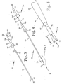
- Figure 1 is an isometric view of one embodiment of the introducer of the present invention as used with a self expanding vascular occlusion device.
- Figure 2 is a partially exploded cross sectional view taken along the line 2-2 of Figure 1.
- Figure 3 is an exploded view of the delivery portion of the delivery portion 32 of the embodiment of Figure 1.
- Figure 4 is a partially exploded view of the embodiment of Figure 1 as seen during assembly.
- Figure 5 is an enlarged view of the area indicated in Figure 4.
- Figure 6 is a cross sectional view taken along the line 6-6 of Figure 1.
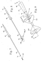
- Figure 7 is an isometric view of the embodiment of Figure 1 as seen during assembly with a self expanding vascular occlusion device exploded away from the introducer.
- Figure 8 is an isometric view of the embodiment of Figure 1 as seen during assembly with a self expanding vascular occlusion device attached from the introducer.
- Figure 9 is an enlarged view of the area indicated in Figure 8.
- Figure 10 is an enlarged view of the area indicated in Figure 1.
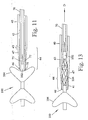
- Fig 11 is a partial cross sectional view along line 11-11 of Figure 9.
- Figure 12 is a cross sectional view of the distal end of the embodiment of Figure 1 as used with a wire coil vascular occlusion device.
- Figure 13 is the view of Figure 11 with a self expanding vascular occlusion device partially retracted into the introducer.
- Figure 14 is an enlarged view of Figure 6 showing how a self expanding vascular occlusion device is released from the retracting portion as the retracting portion is retracted.
- Figure 15 is the view of Figure 14 with the retracting portion removed.
- Figure 16 is a cross sectional view of the embodiment of Figure 1 and a pushing device which may be used to push an expandable implantable device out of the delivery tube.
- Figure 17 is an enlarged view of the area indicated in Figure 16.
- Figure 18 is a cross sectional view of the distal tip of the embodiment shown in Figure 16 with the introduced installed in a catheter and a self expanding vascular occlusion device being pushed from the introducer into the catheter.
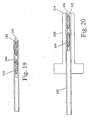
- Figure 19 is a cross sectional view of the proximal end of a delivery portion of a second embodiment of the introducer of the present invention with a self expanding vascular occlusion device retracted into it.
- Figure 20 is a cross sectional view of the proximal end of a delivery portion of a third embodiment of the introducer of the present invention with a self expanding vascular occlusion device retracted into it.
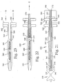
- Figure 21 is a cross sectional view of a fourth embodiment of the introducer of the present invention with a self expanding vascular occlusion device attached to it.
- This embodiment uses a slip sleeve.
- Figure 22 is the view of Figure 21 showing the self expanding vascular occlusion device being retracted into it.
- Figure 23 is the view of Figure 22 with the retracting portion removed showing how the slip sleeve closes.
- Figure 24 is a cross sectional view of a fifth embodiment of the introducer of the present invention with a self expanding vascular occlusion device retracted into it.
- This embodiment uses a spring loaded sliding sleeve.
- Figure 25 is the view of Figure 24 after the device has been released.
- Figure 26 is an alternate embodiment of the retractable portion of the device wherein the retractable portion has an internal metal rod.
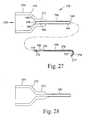
- Figure 27 is a cross sectional partially exploded view of a sixth embodiment of the introducer having a shield on one end.
- Figure 28 is a cross sectional view of a unitarily molded embodiment of a portion of the introducer of Figure 27.
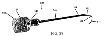
- Figure 29 is a perspective view of the introducer of Figure 27 with a self expanding vascular occlusion device attached.
- Figure 30 is a cross sectional view of a seventh embodiment of the introducer with a self expanding vascular occlusion device attached.
- FIG. 30 an example of one embodiment of the present invention is illustrated and generally indicated by the reference numeral 30.
- the introducer 30 is described below first in terms of its major structural elements and then in terms of its secondary structural and/or functional elements which cooperate to perform the introducing function.
- introducer 30 comprises an outer tubular delivery portion 32 and an inner core portion 34 which slides inside delivery portion 32.
- Inner core 34 has a handle 80 attached to facilitate manual grasping of it.
- Inner core 34 has distal end portion 74 which is tubular and is longitudinally slit to grip an end of an expandable implantable device 100 and hold it at tip 46 of delivery portion 32 until device 100 is to be used.
- inner core 34 is manually pulled proximally, in the direction indicated by arrow A, which pulls expandable device 100 into delivery portion 32 collapsing device 100 as it does so.
- device 100 As inner core 34 is pulled through delivery portion 32, device 100 is pulled proximally inside of delivery portion 32 until distal end portion 74 of inner core 34 reaches gap 68 in delivery portion 32 whereat slit distal end portion 74 expands to release device 100. Inner core 34 is then removed from delivery portion 32. Device 100 is then introduced into a catheter by inserting tip 46 of delivery portion into a catheter and pushing device 100 back through delivery portion 32 using an appropriate diameter pushrod.
- outer delivery portion 32 comprises a delivery tube 40, a hub 50, and a sleeve 60.
- Delivery tube 40 and sleeve 60 are mounted in hub 50 so that a gap 68 of length L1 is left between delivery tube 40 and sleeve 60.
- Hub 50 has a cylindrical shank 52 having a proximal end 54 and a distal end 56.
- shank 52 has a larger diameter portion at distal end 56 to facilitate manual gripping as delivery portion 32 and retracting portion 34 are pulled relative to each other.
- An axial bore 58 extends all the way through hub 50 from proximal end 54 to distal end 56.
- the outer tube 40 has a proximal end portion 42 and a distal end portion 44.
- Proximal end portion 42 is inserted into bore 58 at distal end 56 of hub 50 until a point 48 on delivery tube 40 aligns with distal end 56 of hub 50.
- Delivery tube 40 is then bonded in place with adhesive 92, such as epoxy.
- Distal end portion 44 of delivery tube 40 has an exterior taper 47 to tip 46.
- Sleeve 60 is a tubular body having a distal portion 62 and a proximal portion 64.
- Sleeve 60 has an inner diameter which matches that of delivery tube 40.
- Distal portion 62 of sleeve 60 has an outer diameter which also matches that of delivery tube 40.
- Proximal portion 64 has an outer diameter larger than that of distal portion 62 but smaller than the outer diameter of shank 52 of hub 50.
- Shoulder 66 is formed at the juncture of distal portion 62 and proximal portion 64.
- Distal portion 62 of sleeve 60 is inserted into bore 58 at proximal end 54 of hub 50 until shoulder 66 stops against proximal end 54 of hub 50 and sleeve 60 is bonded in place.
- the lengths of hub 50, proximal end portion 42 of delivery tube 40 and distal portion 62 of sleeve 60 are such that a gap 68 is left between delivery tube 40 and sleeve 60 when they are properly bonded in bore 58 of hub 50. This gap is important to facilitate releasing of an expandable device by retracting portion 34 and care must be taken that material used to bond delivery tube 40 and sleeve 60 into hub 50 does not flow into gap 68.
- inner core 34 comprises a collet tube 70 and handle 80.
- Collet tube 70 has a proximal end portion 72 and a distal end portion 74.
- Collet tube 70 is preferably tubular throughout its length, but it mat be a solid core with only its distal end portion being tubular.
- Distal end portion 74 has a longitudinal slit 76 bifurcating it for a length of L2 into portions 75 and 77.
- handle 80 has an axial bore 82 of sufficient diameter to receive collet tube 70.
- axial bore 82 has a portion 84 of sufficient diameter and length to receive sleeve 60 with a slight friction fit and allow distal end 89 of handle 80 to butt against proximal end 54 of hub 50.
- portion 84 is larger diameter than the rest of axial bore 82, but all of axial bore 82 may have a diameter of portion 84.
- handle 80 has external features such as circumferential grooves 86 to facilitate manual gripping of handle 80.
- Handle 80 is slipped over proximal end portion 72 of collet tube 70, which extends beyond sleeve 60, and slid along collet tube 70 in the direction indicated by arrow C so that sleeve 60 engages portion 84 of axial bore 82 and distal end 89 of handle 80 butts against proximal end 54 of hub 50.
- Collet tube 70 is then further advanced through delivery portion 32 in the direction indicated by arrow B so that distal end portion 74 of collet tube 70 is near tip 46 of delivery tube 40 and proximal end portion 72 of collet tube 70 extends beyond proximal end 88 of handle 80.
- an expandable implantable device such as a vascular occlusion device 100, described in pending U.S. Patent Application, serial number 08/608,110 is installed in distal end portion 74 of collet tube 70.
- Expandable vascular occlusion device 100 has a plurality of hubs 102 and a plurality of braided wires 104 connecting hubs 102. Braided wires 104 have been heat set so that when device 100 is in a relaxed state as shown in figures 7, 8, and 9, device 100 resembles two cones with apexes pointing toward each other. For simplicity, only an outer contour of device 100 is illustrated.
- device 100 When hubs 102 are pulled axially, device 100 stretches into a tubular form of greater length and smaller diameter than it has in its relaxed state. So, the device which is to be used with the introducer of the invention (device 100, stent,...) is adapted for having a relaxed condition of greater diameter and shorter length (see figure 10) and a stretched condition of lesser diameter and longer length.
- An end hub 102 of device 100 is inserted into distal end portion 74 of collet tube 70.
- the inside diameter of collet tube 70 is smaller than the outer diameter of hub 102.
- hub 102 has an outer diameter of 0.030 inches and collet tube 70 has an inner diameter of 0.017 inches.
- the larger diameter of hub 102 forces slot 76 to open as hub 102 is advanced into distal end portion 74 thereby separating portions 75 and 77 of collet tube 70.
- nearly the entire length of hub 102 is inserted into distal end portion 74.
- Length L2 of slot 76 should be long enough that hub 102 can be easily inserted, but short enough that portions 75 and 77 resist being separated and thereby grip hub 102.
- slot length L2 is about twice the length of hub 102.
- collet tube 70 is than further advanced through delivery portion 32 so that portions 75 and 77 are withdrawn into delivery tube 40 and end 79 of collet tube 70 is approximately flush with tip 46 of delivery tube 40. Portions 75 and 77 should not be withdrawn so much into delivery tube 40 that wires 104 are deformed by tip 46 of delivery tube 40.
- adhesive 90 such as epoxy is applied to proximal end 88 of handle 80 and collet tube 70 at proximal end 88 of handle 80 to secure collet tube 70 to handle 80.
- adhesive 90 has solidified, excess collet tube 70 extending beyond adhesive 90 is trimmed off.
- Introducer 30 with expandable implantable device 100 attached is now completed and ready to be stored. It may be sterilized and stored in a sealed transparent bag or tube.
- vascular occlusion coil 110 may be used with introducer 30.
- An end 112 of coil 110 is inserted between portions 75 and 77 of collet tube 70 and withdrawn into tip 46 of delivery tube 40 in a similar manner as was hub 102 of device 100.
- An introducer of the present invention may be suitable for use with any other expandable implantable device, such as a stent, which has a stretched condition characterized by an elongated shape of smaller diameter and a relaxed condition characterized by a shorter shape of larger diameter.
- An implantable device remains attached to the introducer but the device remains in its relaxed condition outside of the introducer. The device is not subject to creep during long term storage in this condition, and the device can be examined to verify the device is appropriate for the intended use before the package containing the device and introducer is opened.
- handle 80 is manually pulled away from hub 50 in the direction indicated be arrow A, which moves collet tube 70 in the direction indicated by arrow D and pulls expandable device 100 into delivery tube 40 collapsing device 100 as it does so.
- distal end portion 44 of delivery tube 40 has an inner wall portion 41 of reduced diameter extending from tip 46 to transition region 45 between inner wall portion 41 and inner wall 43.
- the diameter of inner wall portion 41 is reduced from the diameter of the inner wall 43 along the rest of delivery tube 40 to compensate for the reduced radial stiffness due to the tapering wall thickness in distal end portion 44.
- distal end portion 44 compresses portions 75 and 77 of collet tube 70 firmly against hub 120 like a collet. Portions 75 and 77 exert an outward force on distal portion 44.
- distal portion 44 Because the wall thickness of distal portion 44 is thinner than the rest of delivery tube 40, distal portion 44 will deform outward more than the rest of delivery tube 40. If inner wall portion 41 had a diameter the same as inner wall 43 of the rest of delivery tube 40, the greater outward expansion near tip 46 may reduce the holding force of portions 75 and 77 against hub 102 enough that hub 102 would pull out of collet tube 70 as collet tube 70 is further retracted and frictional resistance of wires 104 against tip 46 is encountered. Such an occurrence would render introducer 30 useless. The reduced diameter of inner wall portion 41 compensates for that by forcing distal end portion 44 to elastically expand more than the rest of delivery tube 40 as portions 75 and 77, and hub 102 pass.
- a greater compression force is exerted on portions 75 and 77 than if the diameter of inner wall portion 41 had not been reduced.
- the compression load of the distal end portion 44 with a thinner wall of lesser inner diameter expanding farther is then similar to that of the rest of delivery tube 40 with a thicker wall of greater inner diameter expanding less. That maintains enough holding force on hub 102 so it does not pull out of collet tube 70 as device 100 is pulled into delivery tube 40.
- the inner diameter of reduced diameter portion 41 is 0.040 inches and the inner diameter of the rest of delivery tube 40 is 0.043 inches.
- the corresponding outer and inner diameters of collet tube 70 are 0.031 and 0.014 inches respectively.
- the outer diameter of hub 102 used with tubes of those dimensions is 0.030 inches, resulting in a 0.004 inch diametric compression.
- braided wires 104 encounter tip 46 which forces wires 104 to collapse as device 100 is stretched and pulled.
- the half of device 100 inside delivery tube 40 has been stretched into a tubular shape tube with braided wires 104 oriented more as illustrated.
- Braided wires 104 bulge out against delivery tube 40 as much as allowed by the diameters of inner wall portions 41 and 43.
- the remaining portion of device 100 is pulled into distal end portion 44 of delivery tube 40.
- collet tube 70 and device 100 is retracted in a direction indicated by arrow E along delivery tube 40 until portions 75 and 77 of collet tube 70 reach gap 68 between delivery tube 40 and sleeve 60 in hub 50.
- portions 75 and 77 are no longer radially constrained by inner wall 43 of delivery tube 40 and they spring open releasing hub 102.
- Collet tube 70 is then pulled the remaining distance out through sleeve 60.
- Gap 68 has a length sufficient to allow portions 75 and 77 to release hub 102. That length is preferably at least as long as the length L2 of slot 76 between portions 75 and 77.
- device 100 is now positioned in delivery tube 40 such that end hub 102 is partially protruding into gap 68. Friction between wires 104 and inner wall 43 keep device 100 in that position.
- Catheter 120 preferably has an inner diameter close to the inner diameter of delivery tube 40, however, it is not necessary to have a close diameter match.
- a catheter could be, for example, 0.007 inches larger.
- a pushrod 95 having an outer diameter similar to that of collet tube 70 is inserted into sleeve 60 and advanced distally in the direction indicated by arrow F until tip 97 contacts hub 102.
- Pushrod 95 may optionally have a handle 96 attached which is similar to handle 80 on collet tube 70.
- Pushrod 95 is then further advanced to push device 100 distally inside of delivery tube 40, out tip 46 of delivery tube 40 and into catheter 120.
- Delivery tube 40 may then optionally be removed from catheter 120 for further advancing of device 100 through catheter 120 with another pushrod or appropriately sized guidewire.
- sleeve 60 helps align a pushrod so it makes proper contact with hub 102 of device 100 when device 100 is to be pushed out of delivery tube 40. however sleeve 60 and even hub 50 are not necessary for an introducer of the present invention to function properly.
- one alternate embodiment is to use only a delivery tube 140 without a sleeve or hub.
- hub 120 When a collet tube is retracted out proximal end 142 of delivery tube 140, hub 120 will be released leaving a portion of hub 120 protruding from proximal end 142.
- Device 100 can be pushed back into delivery tube 140 a little by pinching hub 120 between a person's thumb and forefinger and pushing it into delivery tube 140 resulting in hub 120 being approximately flush with proximal end 142 of delivery tube 140.
- a pushrod can then be applied to hub 120 and used to advance device in tube 140. While construction of this embodiment is simpler, the small outer diameter of delivery tube 140 may make it more difficult to hold when retracting a collet tube or inserting and pushing a pushrod.
- hub 250 attached to tube 240 provides a better grip on delivery tube 240 when retracting a collet tube or inserting and pushing a pushrod.
- Proximal end 254 of hub 25 is preferably flush with proximal end 242 of delivery tube 240.
- Introducer 330 has a delivery tube 340 which may be shorter than in previous embodiments.
- Delivery tube 340 has an axial bore with a distal portion 341 having the same diameter as the inner wall 43 of most of the delivery tube 40 of previous embodiment, and a proximal portion 343 having a diameter of axial bore 58 of hub 50 of a previous embodiment.
- a shoulder 345 is formed at the junction of portion 341 and 343.
- Axial bore proximal portion 343 receives slip sleeve 360.
- Delivery tube has a flange 342 at its proximal end and an external taper 347 at its distal end terminating in tip 346.
- Delivery tube 340 preferably may have a greater wall thickness than delivery tube 40 of previous embodiments and external taper 347 may be steeper than external taper 47 of previous embodiments. In that case it is not necessary that axial bore distal portion 341 have a reduced diameter corresponding to external taper 347.
- Slip sleeve 360 has a flange 364 at its proximal end and a shank 362 extending distally from flange 364 which fits inside axial bore proximal portion 343 of delivery tube 340.
- Slip sleeve 360 is positioned in bore portion 343 to form gap 368 between shoulder 345 and distal end 369 of slip sleeve.
- the fit between shank 362 and bore portion 343 should be a snug sliding fit which is tight enough that gap 368 is maintained during normal handling of introducer 330 and retracing of collet tube 370, but loose enough that gap 368 can be closed by manually sliding slip sleeve distally by pushing on flange 364.
- Slip sleeve 360 has an axial bore 366 of the same diameter as axial bore distal portion 341 of delivery tube 340.
- Collet tube 370 has the same dimensions, except for length, as collet tube 70 of previous embodiments. It has a proximal end 372 bonded to handle 380 and a slot 376 at its distal end which bifurcates it into portions 375 and 377 which hold hub 102 of device 100 at tip 346 of delivery tube 340.
- Handle 380 has an axial bore 382 which receives proximal end 372 of collet tube 370, and a face 384 which abuts flange 364 when device 100 is properly held at tip 346.
- Adhesive 390 affixes handle 380 to collet tube 370.
- Device 100 is drawn into delivery tube 340 in the same manner as with previous embodiments. Delivery tube 340 is held while handle 380 is pulled proximally in a direction indicated by arrow G, which pulls collet tube 370 distally and withdraws device 100 into axial bore distal portion 341 of delivery tube 340. As shown in Figure 22, hub 102 of device 100 is released from collet tube 370 when portions 375 and 377 reach gap 368. Collet tube 370 is then removed from slip sleeve 360.
- slip sleeve 360 is then pushed in a direction indicated by arrow H so that shank 362 slides in axial bore proximal portion 343 of delivery tube 340 until distal end 369 of slip sleeve 360 abuts shoulder 345 of delivery tube 340 thereby closing gap 368.
- Flanges 342 and 364 are then adjacent each other.
- Axial bore distal portion 341 of delivery tube 340 and axial bore 366 of slip sleeve now form a bore having one uniform diameter throughout its length. This is important if a pushrod having a small diameter flexible tip is to be used to push device 100 out of delivery tube 340 and through a catheter.
- gap 368 If gap 368 were left, the larger inner diameter at gap 368 may allow the flexible tip to miss hub 102 of device 100 or buckle while trying to push hub 120, thereby making it impossible to begin pushing device 100 out of delivery tube 340. Closing the gap 368 to make a smaller continuous diameter prevents those occurrences.
- Introducer 330 has an additional advantage of fewer parts and less assembly than the embodiment having the separate hub and sleeve which must be assembled.
- the length of gap 368 can also be adjusted if necessary.
- the relative position of flanges 364 and 342 provide a visual indicator of the length of gap 368.
- Introducer 430 uses a spring loaded sliding sleeve to close the gap.
- Introducer 430 has delivery tube 440 similar to delivery tube 340 of the previous embodiment in that the wall thickness, tip configuration, and dimensions of axial bore distal portion 441, proximal portion 443, and shoulder 445 are the same.
- Delivery tube 440 has a proximal portion 444 and a distal portion 446 joined together at joint 448. Joining may be done by bonding or by designing joint 446 to snap together.
- Proximal portion 444 has a flange 442 at its proximal end and an axial bore 447 of the same diameter as bore 443.
- Slip sleeve 460 has a shank 462 which slides inside bores 443 and 447.
- Axial bore 466 of slip sleeve 460 is slightly smaller than the diameter of bore 441 of delivery tube 440, but still large enough that collet tube 470 will easily slide in it.
- Tabs 464 and 465 protrude in opposite directions through longitudinal slots 450 and 452 in proximal portion 444 of delivery tube 440.
- Springs 449 act between flange 442 and tabs 464 and 465 to keep slip sleeve 460 disposed distally in slots 450 and 452 such that distal end 469 of slip sleeve 460 abuts shoulder 445 of delivery tube 440.
- Collet tube 470 is identical to collet tube 370 of the previous embodiment and has a similar handle (not shown) attached.
- portions 475 and 477 reach distal end 469 of slip sleeve 460. Friction between portion 475 and 477 and 466 slip sleeve 460 caused slip sleeve to slide proximally in the direction indicated by arrows I. That motion continues until portions 475 and 477 clear shoulder 445 at which point hub 102 of device 100 is released from between portions 475 and 477.
- portions 475 and 477 can come back together and slide out of bore 466 as collet tube 470 is removed.
- Springs 449 then push slip sleeve 460 distally until distal end 469 abuts shoulder 445 of delivery tube 440.
- Device 100 can then be pushed distally into a catheter.
- the components of all the above embodiments are preferably made of a thermoplastic material.
- inner core 134 having a metal wire 178 disposed inside collet tube 170.
- Metal wire 178 has a proximal end 177 embedded in adhesive 190 and extends distally along collet tube 170 until it terminates at a distal end 179, which is disposed proximally of slit 176 at distal end portion 174 of collet tube 170.
- Metal wire 178 provides something solid for collet tube 170 to cinch down against as collet tube elongates and shrinks diametrically under tensile load, thereby reducing recoil or "snapping" of collet tube 170 as the inner core 134 is pulled proximally to retract a device.
- Metal wire 178 has an outer diameter that is preferably about 0.002 inches less than the inner diameter of collet tube 170 to aid insertion of metal wire 178 into collet tube 170.
- the wire 178 could be of a larger diameter, as a rod (having a greater rigidity ; not illustrated).
- the embodiment shown in Figure 26 may be used with implantable devices, such as stents, that have no solid hub for the slit distal end portion 174 of collet tube 170 to cinch against.
- distal end 179 of metal wire 178 may extend into slit 176 of distal end portion 174, or beyond collet tube 170 to provide a solid core against which a stent can be clamped by distal end portion 174 of collet tube 170.
- a delivery tube 540 has a cup-shaped transparent shield member 550 affixed to its first end portion 542.
- the shield member 550 protects device 500 and also facilitates introduction of a pusher or guidewire into the delivery tube 540 to push the device 500 into a catheter.
- Collet tube 570 holds a self expanding vascular occlusion device 500, which in this illustration is a ball-shaped device, in a relaxed condition at first end 546 of delivery tube 540 and within shield member 550.
- Second end portion 574 of collet tube 570 extending beyond second end 544 of delivery tube 540 is bent into a hook shape 582 to function as a handle and also to prevent the collet tube 570 from sliding back toward the shield member 550 and releasing device 500.
- Shield member 550 is connected to a first end portion 542 of delivery tube 540.
- Shield member 550 preferably has a shank portion 552 with an internal bore which receives first end portion 542 of delivery tube 540.
- Shank portion 552 is affixed to delivery tube 540 by methods such as gluing or welding, or shank portion 552 may simply have a friction fit on delivery tube 540 and be pressed on it.
- Shield member 550 could also be molded directly onto delivery tube 540.
- shield member 550 and delivery tube 540 could be molded as a single unit. In that case, delivery tube 540 could be an integrally molded extension of shank portion 552.
- Shield member 550 also has cup portion 554 extending from shank portion 552. Cup portion 554 has an internal bore 556 large enough to receive a self expanding vascular occlusion device with generous clearance around the device. Bore 556 has a tapered portion 558 extending from end 546 of delivery tube 540. The tapered portion 548 guides a pusher or guidewire inserted into bore 556 into end 546 of delivery tube 540.
- Delivery tube 540 is similar to delivery tube 40. It is preferably a rigid material such as metal or plastic. First end 546 of delivery tube 540 opens into bore 556 but does not extend into bore 556. First end 546 may have an internal chamfer 548 or radius to facilitate device 500 being pulled into delivery tube 540. Delivery tube 540 has a second end 544 which may have an external chamfer 549 or radius to facilitate it being inserted into a catheter.
- Collet tube 570 is similar to the collet tube of Figure 26 in that, in this embodiment, it has a metal wire 578 disposed inside of a flexible tube, preferably made of material such as polyethylene.
- the first end portion 572 of collet tube 570 has a longitudinal slit 576 which allows first end portion 572 to expand radially to receive and grip an end of device 500.
- Metal wire 578 is coextensive with second end 577 of collet tube 570, and has an end 579 which terminates a significant distance from first end portion 572 of collet tube 570 leaving a portion 580 of collet tube 570 unreinforced by wire 578. Besides providing something solid for collet tube 570 to cinch down against, wire 578 also provides stiffness and memory to second end portion 574 of collet tube 570 so it can be shaped to facilitate grasping.
- second end 577 of collet tube 570 is inserted into first end 546 of delivery tube 540 and pushed through delivery tube 540 until second end portion 574 of collet tube 570 extends beyond second end 544 of delivery tube 540 and slit first end 572 of collet tube 570 extends an inch or so beyond shield member 550.
- An end of device 500 is installed in the slit first end 572 of collet tube 570, then second end portion 574 is pulled to slide collet tube 102 further through delivery tube 540 and pull device 500 inside of cup portion 554 of shield member 550.
- device 500 is held by introducer 530 in its relaxed condition outside of the delivery tube 540 prior to use.
- the hook 582 of the collet tube 570 is grasped and pulled relative to delivery tube 540, which pulls device 500 into delivery tube 540 stretching device 500 to its cylindrical shape as it does so.
- the collet tube 570 moves the device 500 along the delivery tube 540.
- the collet tube 570 releases the device 500 such that most of the device remains in its stretched condition disposed inside the delivery tube 540 at second end 544.
- Collet tube 570 is discarded and second end 544 of the delivery tube 540 is installed in a catheter.
- a push rod is then inserted into first end 546 of delivery tube 540 and advanced until it contacts device 500.
- the pushrod is used to push the device in its stretched condition into the catheter and advance it through the catheter to the desired site of deployment.
- Shield member 550 provides a large diameter grasping member useful for manually holding the catheter while manipulating the pushrod.
- a seventh, and most preferable, embodiment is illustrated in Figure 30.
- the delivery tube 640 and shield member 650 of introducer 630 are the same as delivery tube 540 and shield member 550 in Figure 27.
- the collet tube 670 is similar to collet tube 70 of Figure 2 in that it does not have a metal wire inside of it, and it has a handle 680 attached at its end 674. If collet tube 670 is sufficiently thick and/or rigid, a metal wire is not needed inside of the collet tube.
- the introducer 630 is shown assembled and holding a conical shaped covered self expanding vascular occlusion device 600 in its relaxed state.
- the introducer 630 and device 600 are assembled using the same procedure described above for introducer 530 except that rather than bending the end of the collet tube, after sliding of collet tube 670 in delivery tube 640 is stopped, handle 680, which is a sleeve, is slid over collet tube 670 from end 674 until it reaches end 644 of delivery tube 670. Collet tube 670 and handle680 are then unitized to prevent movement of collet tube 670 in the opposite direction. Any excess collet tubing extending beyond handle 680 is trimmed.
Abstract
An introducer for introducing an expandable implantable device into a catheter
includes an outer tube and an inner core which slides in the outer tube. A first end of the
core has a tubular configuration with a slit which allows it to expand radially to grip an
end of the device. The first end of the core holding the device is pulled into a first end of
the outer tube which further tightens the grip on the device. The second end of the core,
which extends beyond the second end of the outer tube, may have a handle attached or be
bent to prevent the core from moving and releasing the device. The core preferably has a
metal wire inside of it. The device remains in its relaxed condition attached to the
introducer at the first end of the outer tube and mostly outside of it until use. The outer
tube may have a rigid transparent cup-shaped shield member attached at its first end and
extending beyond it to protect the device and allow the device to be viewed on the
introducer. To use the introducer and the device, the core is slid relative to the outer tube
which pulls the device inside the outer tube and into its stretched condition. As the first
end of the inner core exits the second end of the outer tube, the end of the device is
released and remains mostly inside of the outer tube in its stretched condition. An end of
the outer tube is then inserted into a catheter and a pushrod used to push the device from
the introducer into the catheter.
Description
- The present invention relates, generally to medical devices. More particularly, the invention relates to expandable implantable devices, particularly vaso-occlusion devices used in radiology and embolotherapy. Specifically the invention relates to devices and methods for installing vaso-occlusion devices.
- In embolotherapy, it is often desirable to occlude blood flow in a section of vasculature for purposes such as controlling internal bleeding, stopping blood supply to tumors, and relieving vessel-wall pressure in a region of a vessel aneurysm. Several devices and methods have been developed for such purposes, many of which are described in U.S. Patent 4,994,069. Each has significant drawbacks, but the helical wire coils seem to have found the most favor. One difficulty with helical wire coils is in pushing, and, if necessary, pulling them through the catheter. The wire coil is dimensioned to engage the walls of a blood vessel and can be relatively stiff and difficult to advance through a catheter, especially if the blood vessel has a tortuous path. U.S. Patents 5, 226,911 and 5,250,071 describe mechanical devices that attach and detach to the coils to provide more positive pushing, pulling and positioning capability, but they are relatively complex.
- The device of U.S. Patent 4,994,069 (the '069 patent) overcomes many of the problems with wire coils. It provides a smaller coiled wire that when tensioned has a linear configuration allowing it to be advanced through a catheter to the desired site. When the wire exits the catheter, it relaxes and takes a random convoluted shape to form a space-filling mass lodged in the vessel at the site of release. However, because the final shape of the relaxed coil in the blood vessel is random, the precise location and specific length the device occupies in the vessel cannot be guaranteed. Straightening the long coiled wire and inserting it into a catheter can also be problematic.
- A device which overcomes the problems associated with the device of the '069 patent is described in a pending U.S. Patent Application, serial number 08/608,110, titled Self- Expanding Vascular Occlusion Device, filed on February 28, 1996.
- The present invention provides a device and method of loading an expandable vascular occlusion device of the 08/608,110 application into a catheter for insertion into vasculature of a patient. A device and method of the present invention may also be useful to load other expandable devices into catheters, including the device of the '069 patent and other wire coils.
- Expandable implantable devices which could benefit from the present invention include any device which has a stretched condition characterized by an elongated shape of smaller diameter and a relaxed condition characterized by a shorter shape of larger diameter. In the past, such expandable devices have been stored in their stretched condition inside a tube. The device may experience creep during long term storage in that condition. Such creep may prevent the device from fully returning to the intended shape in its relaxed condition. This is especially a problem with devices using plastic material in their springy components. Another potential problem with devices stored in a tubes is that such storage prevents a physician or anyone else from examining the device before it is installed. The storage tube may have a label with a picture or illustration of the device and a description. There is always a potential for mislabeling the tube, or even for the device to be missing from the tube.
- An introducer of the present invention allows an expandable implantable device to be attached to the tip of the introducer, but the device remains in its relaxed condition outside of the introducer. The device is not subject to creep during long term storage in this condition, and the device can be examined to verify the device is appropriate for the intended use before the package containing the device and introducer is opened.
- It is an object of the present invention to provide an introducer for use with an expandable implantable device which holds the device in its relaxed condition outside of the introducer.
- It is another object of the present invention to provide an introducer for use with an expandable implantable device which pulls the device into the introducer, moving it into its stretched condition as it does so.
- It is yet another object of the invention to provide an introducer for use with an expandable implantable device which places the device in its stretched condition in a predetermined position within the introducer.
- The present invention provides an apparatus for introducing a self expanding vascular occlusion device or other expandable implantable device into a catheter. The invention comprises an outer tube and an inner core sliding within an axial bore in the outer tube. The inner core has a distal end, a distal end portion of tubular configuration with at least one slot which allows the distal end portion to expand radially to receive and grip an end of an implantable device. The inner core has a proximal end extending beyond the proximal end of the outer tube when the distal end of the inner core is aligned with the distal end of the outer tube. The expandable implantable device is held by an introducer of the present invention in its relaxed condition outside of the outer tube prior to use.
- An expandable implantable device is attached to an introducer of the present invention by first positioning the inner core relative to the outer tube so that the distal end portion of the inner core extends beyond the distal end of the outer tube. An end of an expandable implantable device is inserted into the distal end of the inner core so that the distal end portion expands radially and grips the end of the device. The inner core is slid proximally to move the distal end portion gripping the end of the implantable device into the outer tube's axial bore at its distal end, thereby tightening the grip of the distal end portion on the end of the implantable device. Proximal motion of inner core is stopped when the distal end of the inner core is aligned with the distal end of said outer tube. A handle may then be attached to the proximal end of the inner core, the handle being constructed and arranged to interact with the proximal end of the outer tube so as to prevent said inner core from sliding distally and releasing the end of the implantable device.
- To use an introducer of the present invention, the inner core is slid proximally which pulls the expandable device into the axial bore of the outer tube tightening the inner core's grip on the end of the device and moving the device to its stretched condition as it does so. Continued sliding of the inner core proximally moves the implantable device along the axial bore of the outer tube. When the distal end of the inner core exits the proximal end of the outer tube, the distal end portion releases the implantable device such that most of the device remains disposed inside the outer tube in its stretched condition. The distal end of the outer tube is then installed in an opening in a catheter and a pushrod is used to push the device in its stretched condition distally back along the axial bore of the outer tube and into the catheter.
- In one embodiment, the introducer further includes a hub having an axial bore which receives the outer tube. The hub has a larger diameter portion to facilitate manual gripping. The proximal end of the hub aligns with the proximal end of the inner tube.
- In another embodiment a similar hub is used. This hub extends proximally beyond the proximal end of said outer tube, and a sleeve is mounted in the axial bore of the hub at the proximal end of the hub. The sleeve has an axial bore with a diameter matching that of the outer tube. The distal end of the sleeve is disposed within the axial bore of the hub and spaced a distance from the proximal end of the outer tube. This gap between the sleeve and the outer tube is sufficiently large to allow the distal portion of said inner core to release the implantable device as the distal end of the inner core exits the proximal end of the outer tube.
- In another embodiment the outer tube has a stepped inner bore with a larger diameter portion at the proximal end, a smaller diameter portion at the distal end, and a shoulder where the two portions meet. A slidable sleeve is selectively positionable along the proximal portion of the axial bore such that the distal end of the sleeve is spaced a distance from the shoulder or the distal end of said sleeve abuts the shoulder. The slidable sleeve has an axial bore the same diameter as the distal portion of the axial bore of the outer tube. When the sleeve is spaced a distance from the shoulder, the implantable device is released from the inner core when the distal end of the inner core passes the shoulder. After the inner core is removed, the sleeve can be slid distally so that the distal end of the sleeve butts against the shoulder thereby closing the gap along the bore. This facilitates use of a push rod having a flexible tip which may miss the implantable device or buckle while trying to push the device back through the outer tube.
- In another similar embodiment a slidable sleeve is spring loaded to keep the gap closed until the distal end portion of the inner core holding the end of the implantable device pushed it open. To facilitate this, the axial bore of the sliding sleeve has a slightly smaller diameter than that of the distal portion of the outer tube, but the diameter is still large enough to allow the inner core to slide smoothly in it. After the implantable device is released from the inner core, the distal end portion of the inner core contracts and slides through the bore of the sleeve and the springs then push the sleeve distally until the gap is again closed.
- All of these embodiments may have a handle attached to the proximal end of the inner core after the implantable device is attached to facilitate manual grasping of the inner core and to prevent said inner core from sliding distally and releasing the end of the implantable device.
- The features, benefits and objects of this invention will become clear to those skilled in the art by reference to the following description, claims and drawings.
- Figure 1 is an isometric view of one embodiment of the introducer of the present invention as used with a self expanding vascular occlusion device.
- Figure 2 is a partially exploded cross sectional view taken along the line 2-2 of Figure 1.
- Figure 3 is an exploded view of the delivery portion of the
delivery portion 32 of the embodiment of Figure 1. - Figure 4 is a partially exploded view of the embodiment of Figure 1 as seen during assembly.
- Figure 5 is an enlarged view of the area indicated in Figure 4.
- Figure 6 is a cross sectional view taken along the line 6-6 of Figure 1.
- Figure 7 is an isometric view of the embodiment of Figure 1 as seen during assembly with a self expanding vascular occlusion device exploded away from the introducer.
- Figure 8 is an isometric view of the embodiment of Figure 1 as seen during assembly with a self expanding vascular occlusion device attached from the introducer.
- Figure 9 is an enlarged view of the area indicated in Figure 8.
- Figure 10 is an enlarged view of the area indicated in Figure 1.
- Fig 11 is a partial cross sectional view along line 11-11 of Figure 9.
- Figure 12 is a cross sectional view of the distal end of the embodiment of Figure 1 as used with a wire coil vascular occlusion device.
- Figure 13 is the view of Figure 11 with a self expanding vascular occlusion device partially retracted into the introducer.
- Figure 14 is an enlarged view of Figure 6 showing how a self expanding vascular occlusion device is released from the retracting portion as the retracting portion is retracted.
- Figure 15 is the view of Figure 14 with the retracting portion removed.
- Figure 16 is a cross sectional view of the embodiment of Figure 1 and a pushing device which may be used to push an expandable implantable device out of the delivery tube.
- Figure 17 is an enlarged view of the area indicated in Figure 16.
- Figure 18 is a cross sectional view of the distal tip of the embodiment shown in Figure 16 with the introduced installed in a catheter and a self expanding vascular occlusion device being pushed from the introducer into the catheter.
- Figure 19 is a cross sectional view of the proximal end of a delivery portion of a second embodiment of the introducer of the present invention with a self expanding vascular occlusion device retracted into it.
- Figure 20 is a cross sectional view of the proximal end of a delivery portion of a third embodiment of the introducer of the present invention with a self expanding vascular occlusion device retracted into it.
- Figure 21 is a cross sectional view of a fourth embodiment of the introducer of the present invention with a self expanding vascular occlusion device attached to it. This embodiment uses a slip sleeve.
- Figure 22 is the view of Figure 21 showing the self expanding vascular occlusion device being retracted into it.
- Figure 23 is the view of Figure 22 with the retracting portion removed showing how the slip sleeve closes.
- Figure 24 is a cross sectional view of a fifth embodiment of the introducer of the present invention with a self expanding vascular occlusion device retracted into it. This embodiment uses a spring loaded sliding sleeve.
- Figure 25 is the view of Figure 24 after the device has been released.
- Figure 26 is an alternate embodiment of the retractable portion of the device wherein the retractable portion has an internal metal rod.
- Figure 27 is a cross sectional partially exploded view of a sixth embodiment of the introducer having a shield on one end.
- Figure 28 is a cross sectional view of a unitarily molded embodiment of a portion of the introducer of Figure 27.
- Figure 29 is a perspective view of the introducer of Figure 27 with a self expanding vascular occlusion device attached.
- Figure 30 is a cross sectional view of a seventh embodiment of the introducer with a self expanding vascular occlusion device attached.
- Referring to Figures 1-15, an example of one embodiment of the present invention is illustrated and generally indicated by the
reference numeral 30. Theintroducer 30 is described below first in terms of its major structural elements and then in terms of its secondary structural and/or functional elements which cooperate to perform the introducing function. - Referring to Figures 1 and 2,
introducer 30 comprises an outertubular delivery portion 32 and aninner core portion 34 which slides insidedelivery portion 32.Inner core 34 has ahandle 80 attached to facilitate manual grasping of it.Inner core 34 hasdistal end portion 74 which is tubular and is longitudinally slit to grip an end of an expandableimplantable device 100 and hold it attip 46 ofdelivery portion 32 untildevice 100 is to be used. At that timeinner core 34 is manually pulled proximally, in the direction indicated by arrow A, which pullsexpandable device 100 intodelivery portion 32 collapsingdevice 100 as it does so. Asinner core 34 is pulled throughdelivery portion 32,device 100 is pulled proximally inside ofdelivery portion 32 untildistal end portion 74 ofinner core 34reaches gap 68 indelivery portion 32 whereat slitdistal end portion 74 expands to releasedevice 100.Inner core 34 is then removed fromdelivery portion 32.Device 100 is then introduced into a catheter by insertingtip 46 of delivery portion into a catheter and pushingdevice 100 back throughdelivery portion 32 using an appropriate diameter pushrod. - Referring to Figures 2 and 3,
outer delivery portion 32 comprises adelivery tube 40, ahub 50, and asleeve 60.Delivery tube 40 andsleeve 60 are mounted inhub 50 so that agap 68 of length L1 is left betweendelivery tube 40 andsleeve 60.Hub 50 has acylindrical shank 52 having aproximal end 54 and adistal end 56. In this embodiment,shank 52 has a larger diameter portion atdistal end 56 to facilitate manual gripping asdelivery portion 32 and retractingportion 34 are pulled relative to each other. Anaxial bore 58 extends all the way throughhub 50 fromproximal end 54 todistal end 56. - The
outer tube 40 has aproximal end portion 42 and adistal end portion 44.Proximal end portion 42 is inserted intobore 58 atdistal end 56 ofhub 50 until apoint 48 ondelivery tube 40 aligns withdistal end 56 ofhub 50.Delivery tube 40 is then bonded in place with adhesive 92, such as epoxy.Distal end portion 44 ofdelivery tube 40 has anexterior taper 47 to tip 46. -
Sleeve 60 is a tubular body having adistal portion 62 and aproximal portion 64.Sleeve 60 has an inner diameter which matches that ofdelivery tube 40.Distal portion 62 ofsleeve 60 has an outer diameter which also matches that ofdelivery tube 40.Proximal portion 64 has an outer diameter larger than that ofdistal portion 62 but smaller than the outer diameter ofshank 52 ofhub 50.Shoulder 66 is formed at the juncture ofdistal portion 62 andproximal portion 64.Distal portion 62 ofsleeve 60 is inserted intobore 58 atproximal end 54 ofhub 50 untilshoulder 66 stops againstproximal end 54 ofhub 50 andsleeve 60 is bonded in place. The lengths ofhub 50,proximal end portion 42 ofdelivery tube 40 anddistal portion 62 ofsleeve 60 are such that agap 68 is left betweendelivery tube 40 andsleeve 60 when they are properly bonded inbore 58 ofhub 50. This gap is important to facilitate releasing of an expandable device by retractingportion 34 and care must be taken that material used tobond delivery tube 40 andsleeve 60 intohub 50 does not flow intogap 68. - Referring to Figures 2, 4, and 5,
inner core 34 comprises acollet tube 70 and handle 80.Collet tube 70 has aproximal end portion 72 and adistal end portion 74.Collet tube 70 is preferably tubular throughout its length, but it mat be a solid core with only its distal end portion being tubular.Distal end portion 74 has alongitudinal slit 76 bifurcating it for a length of L2 intoportions delivery portion 32 has been assembled,proximal end portion 72 ofcollet tube 70 is inserted intotip 46 ofdelivery tube 40 and slid throughdelivery portion 32 in the direction indicated be arrow B so thatproximal end portion 72 extends well beyondsleeve 60. - Referring to Figures 2, 4, and 6, handle 80 has an
axial bore 82 of sufficient diameter to receivecollet tube 70. Atdistal end 89 ofhandle 80,axial bore 82 has aportion 84 of sufficient diameter and length to receivesleeve 60 with a slight friction fit and allowdistal end 89 ofhandle 80 to butt againstproximal end 54 ofhub 50. In this embodiment,portion 84 is larger diameter than the rest ofaxial bore 82, but all ofaxial bore 82 may have a diameter ofportion 84. In this embodiment, handle 80 has external features such ascircumferential grooves 86 to facilitate manual gripping ofhandle 80. -
Handle 80 is slipped overproximal end portion 72 ofcollet tube 70, which extends beyondsleeve 60, and slid alongcollet tube 70 in the direction indicated by arrow C so thatsleeve 60 engagesportion 84 ofaxial bore 82 anddistal end 89 ofhandle 80 butts againstproximal end 54 ofhub 50.Collet tube 70 is then further advanced throughdelivery portion 32 in the direction indicated by arrow B so thatdistal end portion 74 ofcollet tube 70 is neartip 46 ofdelivery tube 40 andproximal end portion 72 ofcollet tube 70 extends beyondproximal end 88 ofhandle 80. - Referring to Figures 7, 8, and 9, an expandable implantable device such as a
vascular occlusion device 100, described in pending U.S. Patent Application, serial number 08/608,110 is installed indistal end portion 74 ofcollet tube 70. Expandablevascular occlusion device 100 has a plurality ofhubs 102 and a plurality of braidedwires 104 connectinghubs 102.Braided wires 104 have been heat set so that whendevice 100 is in a relaxed state as shown in figures 7, 8, and 9,device 100 resembles two cones with apexes pointing toward each other. For simplicity, only an outer contour ofdevice 100 is illustrated. Whenhubs 102 are pulled axially,device 100 stretches into a tubular form of greater length and smaller diameter than it has in its relaxed state. So, the device which is to be used with the introducer of the invention (device 100, stent,...) is adapted for having a relaxed condition of greater diameter and shorter length (see figure 10) and a stretched condition of lesser diameter and longer length. - An
end hub 102 ofdevice 100 is inserted intodistal end portion 74 ofcollet tube 70. The inside diameter ofcollet tube 70 is smaller than the outer diameter ofhub 102. In one embodiment,hub 102 has an outer diameter of 0.030 inches andcollet tube 70 has an inner diameter of 0.017 inches. The larger diameter ofhub 102forces slot 76 to open ashub 102 is advanced intodistal end portion 74 thereby separatingportions collet tube 70. Preferably, nearly the entire length ofhub 102 is inserted intodistal end portion 74. Length L2 ofslot 76 should be long enough thathub 102 can be easily inserted, but short enough thatportions grip hub 102. In this embodiment, slot length L2 is about twice the length ofhub 102. - Referring to Figures 1, 10 and 11, with
device 100 held byportions collet tube 70,collet tube 70 is than further advanced throughdelivery portion 32 so thatportions delivery tube 40 and end 79 ofcollet tube 70 is approximately flush withtip 46 ofdelivery tube 40.Portions delivery tube 40 thatwires 104 are deformed bytip 46 ofdelivery tube 40. - Referring to Figures 1 and 6, with
device 100 properly positioned relative todelivery tube 40, adhesive 90 such as epoxy is applied toproximal end 88 ofhandle 80 andcollet tube 70 atproximal end 88 ofhandle 80 to securecollet tube 70 to handle 80. After adhesive 90 has solidified,excess collet tube 70 extending beyond adhesive 90 is trimmed off.Introducer 30 with expandableimplantable device 100 attached is now completed and ready to be stored. It may be sterilized and stored in a sealed transparent bag or tube. - Referring to Figure 12, other expandable implantable devices such as
vascular occlusion coil 110 may be used withintroducer 30. Anend 112 ofcoil 110 is inserted betweenportions collet tube 70 and withdrawn intotip 46 ofdelivery tube 40 in a similar manner as washub 102 ofdevice 100. - An introducer of the present invention may be suitable for use with any other expandable implantable device, such as a stent, which has a stretched condition characterized by an elongated shape of smaller diameter and a relaxed condition characterized by a shorter shape of larger diameter. An implantable device remains attached to the introducer but the device remains in its relaxed condition outside of the introducer. The device is not subject to creep during long term storage in this condition, and the device can be examined to verify the device is appropriate for the intended use before the package containing the device and introducer is opened.
- Referring to Figures 1, 11 and 13, when an implantable device such as
device 100, is to be introduce into a catheter, handle 80 is manually pulled away fromhub 50 in the direction indicated be arrow A, which movescollet tube 70 in the direction indicated by arrow D and pullsexpandable device 100 intodelivery tube 40 collapsingdevice 100 as it does so. - Referring to Figure 11,
distal end portion 44 ofdelivery tube 40 has aninner wall portion 41 of reduced diameter extending fromtip 46 to transitionregion 45 betweeninner wall portion 41 andinner wall 43. The diameter ofinner wall portion 41 is reduced from the diameter of theinner wall 43 along the rest ofdelivery tube 40 to compensate for the reduced radial stiffness due to the tapering wall thickness indistal end portion 44. Ashub 102 andportions collet tube 70 are drawn intodistal end portion 44 ofdelivery tube 40,distal end portion 44compresses portions collet tube 70 firmly againsthub 120 like a collet.Portions distal portion 44. Because the wall thickness ofdistal portion 44 is thinner than the rest ofdelivery tube 40,distal portion 44 will deform outward more than the rest ofdelivery tube 40. Ifinner wall portion 41 had a diameter the same asinner wall 43 of the rest ofdelivery tube 40, the greater outward expansion neartip 46 may reduce the holding force ofportions hub 102 enough thathub 102 would pull out ofcollet tube 70 ascollet tube 70 is further retracted and frictional resistance ofwires 104 againsttip 46 is encountered. Such an occurrence would renderintroducer 30 useless. The reduced diameter ofinner wall portion 41 compensates for that by forcingdistal end portion 44 to elastically expand more than the rest ofdelivery tube 40 asportions hub 102 pass. A greater compression force is exerted onportions inner wall portion 41 had not been reduced. The compression load of thedistal end portion 44 with a thinner wall of lesser inner diameter expanding farther is then similar to that of the rest ofdelivery tube 40 with a thicker wall of greater inner diameter expanding less. That maintains enough holding force onhub 102 so it does not pull out ofcollet tube 70 asdevice 100 is pulled intodelivery tube 40. - In one embodiment, the inner diameter of reduced
diameter portion 41 is 0.040 inches and the inner diameter of the rest ofdelivery tube 40 is 0.043 inches. The corresponding outer and inner diameters ofcollet tube 70 are 0.031 and 0.014 inches respectively. The outer diameter ofhub 102 used with tubes of those dimensions is 0.030 inches, resulting in a 0.004 inch diametric compression. - Referring to Figure 13, as
device 100 is pulled intodistal end portion 44 ofdelivery tube 40, braidedwires 104encounter tip 46 which forceswires 104 to collapse asdevice 100 is stretched and pulled. The half ofdevice 100 insidedelivery tube 40 has been stretched into a tubular shape tube with braidedwires 104 oriented more as illustrated.Braided wires 104 bulge out againstdelivery tube 40 as much as allowed by the diameters ofinner wall portions device 100 is pulled intodistal end portion 44 ofdelivery tube 40. - Referring to Figure 14,
collet tube 70 anddevice 100 is retracted in a direction indicated by arrow E alongdelivery tube 40 untilportions collet tube 70reach gap 68 betweendelivery tube 40 andsleeve 60 inhub 50. Asend 79 of collet tube emerges fromdelivery tube 40,portions inner wall 43 ofdelivery tube 40 and they spring open releasinghub 102.Collet tube 70 is then pulled the remaining distance out throughsleeve 60.Gap 68 has a length sufficient to allowportions hub 102. That length is preferably at least as long as the length L2 ofslot 76 betweenportions - Referring to Figures 15,
device 100 is now positioned indelivery tube 40 such thatend hub 102 is partially protruding intogap 68. Friction betweenwires 104 andinner wall 43 keepdevice 100 in that position. - Referring to Figures 16, 17 and 18, to introduce
device 100 into acatheter 120,external taper 47 ofdelivery tube 40 is inserted into anend 122 ofcatheter 120, which frictionally holdsdelivery tube 40 in place.Catheter 120 preferably has an inner diameter close to the inner diameter ofdelivery tube 40, however, it is not necessary to have a close diameter match. A catheter could be, for example, 0.007 inches larger. Apushrod 95 having an outer diameter similar to that ofcollet tube 70 is inserted intosleeve 60 and advanced distally in the direction indicated by arrow F untiltip 97contacts hub 102.Pushrod 95 may optionally have ahandle 96 attached which is similar to handle 80 oncollet tube 70.Pushrod 95 is then further advanced to pushdevice 100 distally inside ofdelivery tube 40, outtip 46 ofdelivery tube 40 and intocatheter 120.Delivery tube 40 may then optionally be removed fromcatheter 120 for further advancing ofdevice 100 throughcatheter 120 with another pushrod or appropriately sized guidewire. - Referring to Figure 15,
sleeve 60 helps align a pushrod so it makes proper contact withhub 102 ofdevice 100 whendevice 100 is to be pushed out ofdelivery tube 40. howeversleeve 60 and evenhub 50 are not necessary for an introducer of the present invention to function properly. - Referring to Figure 19, one alternate embodiment is to use only a
delivery tube 140 without a sleeve or hub. When a collet tube is retracted outproximal end 142 ofdelivery tube 140,hub 120 will be released leaving a portion ofhub 120 protruding fromproximal end 142.Device 100 can be pushed back into delivery tube 140 a little by pinchinghub 120 between a person's thumb and forefinger and pushing it intodelivery tube 140 resulting inhub 120 being approximately flush withproximal end 142 ofdelivery tube 140. A pushrod can then be applied tohub 120 and used to advance device intube 140. While construction of this embodiment is simpler, the small outer diameter ofdelivery tube 140 may make it more difficult to hold when retracting a collet tube or inserting and pushing a pushrod. - Referring to Figure 20, another alternate embodiment shown works the same way as the embodiment of figure 15, but
hub 250 attached totube 240 provides a better grip ondelivery tube 240 when retracting a collet tube or inserting and pushing a pushrod.Proximal end 254 of hub 25 is preferably flush withproximal end 242 ofdelivery tube 240. - Referring to Figures 21, 22 and 23, another embodiment of an introducer of the present invention is shown in longitudinal cross section.
Introducer 330 has adelivery tube 340 which may be shorter than in previous embodiments.Delivery tube 340 has an axial bore with adistal portion 341 having the same diameter as theinner wall 43 of most of thedelivery tube 40 of previous embodiment, and aproximal portion 343 having a diameter ofaxial bore 58 ofhub 50 of a previous embodiment. Ashoulder 345 is formed at the junction ofportion proximal portion 343 receivesslip sleeve 360. Delivery tube has aflange 342 at its proximal end and anexternal taper 347 at its distal end terminating intip 346.Delivery tube 340 preferably may have a greater wall thickness thandelivery tube 40 of previous embodiments andexternal taper 347 may be steeper thanexternal taper 47 of previous embodiments. In that case it is not necessary that axial boredistal portion 341 have a reduced diameter corresponding toexternal taper 347. -
Slip sleeve 360 has aflange 364 at its proximal end and ashank 362 extending distally fromflange 364 which fits inside axial boreproximal portion 343 ofdelivery tube 340.Slip sleeve 360 is positioned inbore portion 343 to formgap 368 betweenshoulder 345 anddistal end 369 of slip sleeve. The fit betweenshank 362 and boreportion 343 should be a snug sliding fit which is tight enough thatgap 368 is maintained during normal handling ofintroducer 330 and retracing ofcollet tube 370, but loose enough thatgap 368 can be closed by manually sliding slip sleeve distally by pushing onflange 364.Slip sleeve 360 has anaxial bore 366 of the same diameter as axial boredistal portion 341 ofdelivery tube 340. -
Collet tube 370 has the same dimensions, except for length, ascollet tube 70 of previous embodiments. It has aproximal end 372 bonded to handle 380 and aslot 376 at its distal end which bifurcates it intoportions hub 102 ofdevice 100 attip 346 ofdelivery tube 340. - Handle 380 has an
axial bore 382 which receivesproximal end 372 ofcollet tube 370, and aface 384 which abutsflange 364 whendevice 100 is properly held attip 346.Adhesive 390 affixes handle 380 tocollet tube 370. -
Device 100 is drawn intodelivery tube 340 in the same manner as with previous embodiments.Delivery tube 340 is held whilehandle 380 is pulled proximally in a direction indicated by arrow G, which pullscollet tube 370 distally and withdrawsdevice 100 into axial boredistal portion 341 ofdelivery tube 340. As shown in Figure 22,hub 102 ofdevice 100 is released fromcollet tube 370 whenportions reach gap 368.Collet tube 370 is then removed fromslip sleeve 360. - Referring to Figure 23,
slip sleeve 360 is then pushed in a direction indicated by arrow H so thatshank 362 slides in axial boreproximal portion 343 ofdelivery tube 340 untildistal end 369 ofslip sleeve 360 abutsshoulder 345 ofdelivery tube 340 thereby closinggap 368.Flanges distal portion 341 ofdelivery tube 340 andaxial bore 366 of slip sleeve now form a bore having one uniform diameter throughout its length. This is important if a pushrod having a small diameter flexible tip is to be used to pushdevice 100 out ofdelivery tube 340 and through a catheter. Ifgap 368 were left, the larger inner diameter atgap 368 may allow the flexible tip to misshub 102 ofdevice 100 or buckle while trying to pushhub 120, thereby making it impossible to begin pushingdevice 100 out ofdelivery tube 340. Closing thegap 368 to make a smaller continuous diameter prevents those occurrences.Introducer 330 has an additional advantage of fewer parts and less assembly than the embodiment having the separate hub and sleeve which must be assembled. The length ofgap 368 can also be adjusted if necessary. The relative position offlanges gap 368. - Referring to Figure 24, another embodiment of an introducer of the present invention uses a spring loaded sliding sleeve to close the gap. Introducer 430 has
delivery tube 440 similar todelivery tube 340 of the previous embodiment in that the wall thickness, tip configuration, and dimensions of axial boredistal portion 441,proximal portion 443, andshoulder 445 are the same.Delivery tube 440 has aproximal portion 444 and adistal portion 446 joined together at joint 448. Joining may be done by bonding or by designing joint 446 to snap together.Proximal portion 444 has aflange 442 at its proximal end and anaxial bore 447 of the same diameter asbore 443. -
Slip sleeve 460 has ashank 462 which slides inside bores 443 and 447. Axial bore 466 ofslip sleeve 460 is slightly smaller than the diameter ofbore 441 ofdelivery tube 440, but still large enough thatcollet tube 470 will easily slide in it.Tabs longitudinal slots proximal portion 444 ofdelivery tube 440.Springs 449 act betweenflange 442 andtabs slip sleeve 460 disposed distally inslots distal end 469 ofslip sleeve 460 abutsshoulder 445 ofdelivery tube 440.Collet tube 470 is identical tocollet tube 370 of the previous embodiment and has a similar handle (not shown) attached. - As
collet tube 70 retracts proximally in a direction indicated by arrow G and pullsdevice 100 intodelivery tube 440,portions distal end 469 ofslip sleeve 460. Friction betweenportion slip sleeve 460 caused slip sleeve to slide proximally in the direction indicated by arrows I. That motion continues untilportions clear shoulder 445 at whichpoint hub 102 ofdevice 100 is released from betweenportions - Referring to Figure 25, as collet tube continues to be retracted in the direction indicated by arrow G,
portions bore 466 ascollet tube 470 is removed.Springs 449 then pushslip sleeve 460 distally untildistal end 469 abutsshoulder 445 ofdelivery tube 440.Device 100 can then be pushed distally into a catheter. The components of all the above embodiments are preferably made of a thermoplastic material. - Referring to Figure 26, another embodiment of the
inner core 34 which applies to all other embodiments above isinner core 134 having ametal wire 178 disposed insidecollet tube 170.Metal wire 178 has aproximal end 177 embedded in adhesive 190 and extends distally alongcollet tube 170 until it terminates at adistal end 179, which is disposed proximally ofslit 176 atdistal end portion 174 ofcollet tube 170.Metal wire 178 provides something solid forcollet tube 170 to cinch down against as collet tube elongates and shrinks diametrically under tensile load, thereby reducing recoil or "snapping" ofcollet tube 170 as theinner core 134 is pulled proximally to retract a device.Metal wire 178 has an outer diameter that is preferably about 0.002 inches less than the inner diameter ofcollet tube 170 to aid insertion ofmetal wire 178 intocollet tube 170. - The
wire 178 could be of a larger diameter, as a rod (having a greater rigidity ; not illustrated). - The embodiment shown in Figure 26 may be used with implantable devices, such as stents, that have no solid hub for the slit
distal end portion 174 ofcollet tube 170 to cinch against. In that case,distal end 179 ofmetal wire 178 may extend intoslit 176 ofdistal end portion 174, or beyondcollet tube 170 to provide a solid core against which a stent can be clamped bydistal end portion 174 ofcollet tube 170. - Referring to Figures 27-29, a sixth, embodiment of the
introducer 530 is illustrated. Adelivery tube 540 has a cup-shapedtransparent shield member 550 affixed to itsfirst end portion 542. Theshield member 550 protectsdevice 500 and also facilitates introduction of a pusher or guidewire into thedelivery tube 540 to push thedevice 500 into a catheter.Collet tube 570 holds a self expandingvascular occlusion device 500, which in this illustration is a ball-shaped device, in a relaxed condition atfirst end 546 ofdelivery tube 540 and withinshield member 550.Second end portion 574 ofcollet tube 570 extending beyondsecond end 544 ofdelivery tube 540 is bent into ahook shape 582 to function as a handle and also to prevent thecollet tube 570 from sliding back toward theshield member 550 and releasingdevice 500. -
Shield member 550 is connected to afirst end portion 542 ofdelivery tube 540.Shield member 550 preferably has ashank portion 552 with an internal bore which receivesfirst end portion 542 ofdelivery tube 540.Shank portion 552 is affixed todelivery tube 540 by methods such as gluing or welding, orshank portion 552 may simply have a friction fit ondelivery tube 540 and be pressed on it.Shield member 550 could also be molded directly ontodelivery tube 540. Alternatively, as illustrated in Figure 28,shield member 550 anddelivery tube 540 could be molded as a single unit. In that case,delivery tube 540 could be an integrally molded extension ofshank portion 552. -
Shield member 550 also hascup portion 554 extending fromshank portion 552.Cup portion 554 has aninternal bore 556 large enough to receive a self expanding vascular occlusion device with generous clearance around the device.Bore 556 has a tapered portion 558 extending fromend 546 ofdelivery tube 540. The taperedportion 548 guides a pusher or guidewire inserted intobore 556 intoend 546 ofdelivery tube 540. -
Delivery tube 540 is similar todelivery tube 40. It is preferably a rigid material such as metal or plastic.First end 546 ofdelivery tube 540 opens intobore 556 but does not extend intobore 556.First end 546 may have aninternal chamfer 548 or radius to facilitatedevice 500 being pulled intodelivery tube 540.Delivery tube 540 has asecond end 544 which may have anexternal chamfer 549 or radius to facilitate it being inserted into a catheter. -
Collet tube 570 is similar to the collet tube of Figure 26 in that, in this embodiment, it has ametal wire 578 disposed inside of a flexible tube, preferably made of material such as polyethylene. Thefirst end portion 572 ofcollet tube 570 has alongitudinal slit 576 which allowsfirst end portion 572 to expand radially to receive and grip an end ofdevice 500. -
Metal wire 578 is coextensive withsecond end 577 ofcollet tube 570, and has anend 579 which terminates a significant distance fromfirst end portion 572 ofcollet tube 570 leaving aportion 580 ofcollet tube 570 unreinforced bywire 578. Besides providing something solid forcollet tube 570 to cinch down against,wire 578 also provides stiffness and memory tosecond end portion 574 ofcollet tube 570 so it can be shaped to facilitate grasping. - To install a
device 500 in theintroducer 530,second end 577 ofcollet tube 570 is inserted intofirst end 546 ofdelivery tube 540 and pushed throughdelivery tube 540 untilsecond end portion 574 ofcollet tube 570 extends beyondsecond end 544 ofdelivery tube 540 and slitfirst end 572 ofcollet tube 570 extends an inch or so beyondshield member 550. An end ofdevice 500 is installed in the slitfirst end 572 ofcollet tube 570, thensecond end portion 574 is pulled to slidecollet tube 102 further throughdelivery tube 540 and pulldevice 500 inside ofcup portion 554 ofshield member 550. When theend 572 ofcollet tube 570 gripping thedevice 500 enters thefirst end 546 ofdelivery tube 540, the grip ofend 572 ofcollet tube 570 on the end ofdevice 500 is tightened by compressive loading ofend 572 ofcollet tube 570. Sliding ofcollet tube 570 is then stopped.Second end portion 574 ofcollet tube 570 is then bent to form ahook 582 atsecond end 544 ofdelivery tube 540. Thehook 582 serves as a handle for graspingcollet tube 570 to retract device intodelivery tube 540, and also functions to prevent thecollet tube 570 from sliding back toward theshield member 550 and releasingdevice 500. - As shown in Figure 29,
device 500 is held byintroducer 530 in its relaxed condition outside of thedelivery tube 540 prior to use. To use the device and the introducer, thehook 582 of thecollet tube 570 is grasped and pulled relative todelivery tube 540, which pullsdevice 500 intodelivery tube 540stretching device 500 to its cylindrical shape as it does so. Continued sliding of thecollet tube 570 moves thedevice 500 along thedelivery tube 540. When thefirst end 572 of thecollet tube 570 exitssecond end 544 of thedelivery tube 540, thecollet tube 570 releases thedevice 500 such that most of the device remains in its stretched condition disposed inside thedelivery tube 540 atsecond end 544.Collet tube 570 is discarded andsecond end 544 of thedelivery tube 540 is installed in a catheter. A push rod is then inserted intofirst end 546 ofdelivery tube 540 and advanced until itcontacts device 500. The pushrod is used to push the device in its stretched condition into the catheter and advance it through the catheter to the desired site of deployment.Shield member 550 provides a large diameter grasping member useful for manually holding the catheter while manipulating the pushrod. - A seventh, and most preferable, embodiment is illustrated in Figure 30. The
delivery tube 640 andshield member 650 ofintroducer 630 are the same asdelivery tube 540 andshield member 550 in Figure 27. Thecollet tube 670 is similar tocollet tube 70 of Figure 2 in that it does not have a metal wire inside of it, and it has ahandle 680 attached at itsend 674. Ifcollet tube 670 is sufficiently thick and/or rigid, a metal wire is not needed inside of the collet tube. Theintroducer 630 is shown assembled and holding a conical shaped covered self expandingvascular occlusion device 600 in its relaxed state. Theintroducer 630 anddevice 600 are assembled using the same procedure described above forintroducer 530 except that rather than bending the end of the collet tube, after sliding ofcollet tube 670 indelivery tube 640 is stopped, handle 680, which is a sleeve, is slid overcollet tube 670 fromend 674 until it reaches end 644 ofdelivery tube 670.Collet tube 670 and handle680 are then unitized to prevent movement ofcollet tube 670 in the opposite direction. Any excess collet tubing extending beyondhandle 680 is trimmed. - The descriptions above and the accompanying drawings should be interpreted in the illustrative and not the limited sense. While the invention has been disclosed in connection with the preferred embodiment or embodiments thereof, it should be understood that there may be other embodiments which fall within the scope of the invention as defined by the following claims. Where a claim is expressed as a means or step for performing a specified function it is intended that such claim be construed to cover the corresponding structure, material, or acts described in the specification and equivalents thereof, including both structural equivalents and equivalent structures.
Claims (30)
- An introducer for introducing an implantable device (100) into a catheter, comprising:(a) a delivery tube (40) having a first end, a second end and an axial bore (58),(b) an inner core (34) slidably disposed inside the axial bore of the delivery tube, the inner core having a first end, a first end portion of tubular configuration with at least one slot (76) which allows the first end portion to expand radially to receive and grip an end of the implantable device (100), the inner core having a second end portion (72) extending beyond the second end (42) of the delivery tube when the first end of the inner core is aligned with the first end of the delivery tube.
- The introducer of claim 1, characterized in that the delivery tube has a first end portion (44) having an external taper (47).
- The introducer of claim 1 or claim 2, characterized in that the axial bore (58) of the delivery tube (40) has a second portion of greater diameter and a first portion of lesser diameter, the first portion being adjacent the external taper (47).
- The introducer of anyone of claims 1 to 3, characterized in that it further comprises a handle (80) connected to the second end portion of the inner core (34).
- The introducer of anyone of claims 1 to 4, characterized in that it further comprises a wire or a rod (178) disposed inside the inner core (34).
- The introducer of claim 5, characterized in that the wire or the rod (178) has a first end disposed a substantial distance from the at least one slot (76).
- The introducer of claim 5, characterized in that the inner core (34) has a second end, and the wire or the rod (178) has a second end disposed at the second end of the inner core.
- The introducer of anyone of claims 5 to 7, characterized in that the inner core (34) is tubular having an inner diameter, and the wire or the rod (178) has an outer diameter that is less than the inner diameter of the tubular inner core.
- The introducer of anyone of claims 1 to 8, characterized in that it further comprises a hub (50) connected to the delivery tube (40), the hub having an axial bore (58) which receives the delivery tube, a first end (54), a first portion of larger outer diameter, a second portion of smaller outer diameter, and a second end (56); the delivery tube being received in the axial bore of the hub and the delivery tube extending beyond the first end (54) of the hub.
- The introducer of claim 9, characterized in that the second end of the delivery tube aligns with the second end (56) of the hub (50).
- The introducer of claim 10, characterized in that it further comprises a handle (80) connected to the second end (72) of the inner core (34), the handle being disposed adjacent the hub (50) when the first end (74) of the inner core is aligned with the first end (44) of the delivery tube (40).
- The introducer of anyone of claims 9 to 11, characterized in that the second end (56) of the hub (50) extends beyond the second end of the delivery tube (40).
- The introducer of claim 11 or claim 12, characterized in that it further comprises a sleeve (60) received by the axial bore (58) of the hub (50) at the second end of the hub, the sleeve having a first end, a second end and an axial bore, the axial bore of the sleeve receiving the inner core (34), the first end of the sleeve being disposed within the axial bore (58) of the hub and spaced a distance from the second end of the delivery tube (40), the distance being sufficiently long to allow the first portion (74) of the inner core (34) to release the implantable device (100) as the first end of the inner core exits the second end (42) of the delivery tube.
- The introducer of claim 13, characterized in that the axial bore of the sleeve (60) and the axial bore of the delivery tube (40) are of the same diameter.
- The introducer of claim 13 or claim 14, characterized in that the second end of the sleeve (60) extends beyond the second end of the hub (50).
- The introducer of anyone of claims 11 to 15, characterized in that the handle (80) has a recess which receives the second end of the sleeve (60), the handle being disposed adjacent the hub (50) when the first end of the inner core (34) is aligned with the first end of the delivery tube (40).
- The introducer of claim 2, characterized in that:(a) the delivery tube (40) has a flange on the second end;(b) the axial bore (58) of the delivery tube has a second portion of greater diameter which receives a sleeve (60), a first portion of lesser diameter which receives the inner core, and a shoulder (66) where the second portion meets the first portion; and further comprising:(c) a sleeve (60) slidably engaging the second portion of the axial bore (58) of the delivery tube, the sleeve having an axial bore which receives the inner core, a first end, a second end, a flange at the second end, a shank (52) extending from the flange and into the second portion of the axial bore of the delivery tube, the sleeve being selectively positionable along the second portion of the axial bore of the delivery tube such that :the first end of the sleeve is spaced a distance from the shoulder,or, the first end of the sleeve abuts the shoulder (66), and when the sleeve is spaced a distance from the shoulder, the implantable device is released from the inner core when the first end of the inner core passes the shoulder.
- The introducer of claim 17, characterized in that the shank (52) of the sleeve (60) has a length such that a distance between the flange on the delivery tube (40) and the flange on the sleeve is substantially the same as the distance between the shoulder (66) in the delivery tube and the first end of the sleeve.
- The introducer of claim 18, characterized in that the axial bore of the sleeve (60) and the first portion of the axial bore of the delivery tube (40) are of substantially the same diameter.
- The introducer of claim 18 or 19, characterized in that the handle (80) is adjacent the flange on the sleeve (60) when the first end of the inner core is aligned with the first end of the delivery tube (40) and the sleeve is positioned so that the first end of the sleeve is spaced from the shoulder in the delivery tube.
- The introducer of claim 17, characterized in that the sleeve (60) is spring loaded against the flange of the delivery tube (40) to normally keep the first end of the sleeve butted against the shoulder (66), but when the first end portion of the inner core (34) gripping an end of an implantable device (100) reaches the first end of the sleeve, the sleeve moves with the first end portion of the inner core until the first end of the inner core passes the shoulder and releases the implantable device, whereupon the first portion of the inner core contracts radially and the sleeve slides over the first end portion of the inner core until the first end of the sleeve once again butts against the shoulder.
- The introducer of claim 1, characterized in that the delivery tube (40) has a first end portion, and further comprising a shield member (550) connected to the first end portion of the delivery tube, the shield member having a cavity sufficiently large to receive the implantable device (100) in a relaxed condition, the cavity communicating with the axial bore of the delivery tube.
- The introducer of claim 22, characterized in that it further comprises a handle (80) disposed on and attached to the second end portion of the inner core (34) and adjacent the second end of the delivery tube (40) when the first end of the inner core is aligned with the first end of the delivery tube.
- The introducer of claim 1 or claim 7, characterized in that the second end portion of the inner core (34) is bent in the shape of a hook.
- The introducer according to anyone of claims 1 to 24,characterized in that the inner core (34) is sliding hrough the axial bore of the delivery tube (40) to pull the implantable device(100) into the axial bore of the delivery tube, the first end portion of the inner core releasing the implantable device when the first end of the inner core exits the second end of the delivery tube such that a portion of the implantable device remains disposed inside the delivery tube.
- A system for providing an expandable implantable device (100) for introduction into a catheter, comprising:(a) the expandable implantable device having an end, a relaxed condition of greater diameter and shorter length, and a stretched condition of lesser diameter and longer length; and(b) an introducer (30) for introducing the expandable implantable device into a catheter, the introducer having:a delivery tube (40) having a first end, a second end and an axial bore (58);an inner core (34) slidably disposed inside the axial bore of the delivery tube, the inner core having a first end, a first end portion constructed to receive and grip the end of the implantable device, the end of the expandable device disposed in and gripped by the first end portion of the inner core, the first end portion with the end of the implantable device disposed in the axial bore of the delivery tube at the first end of the delivery tube so that the implantable device remains in the relaxed condition and most of the implantable device is outside of the delivery tube, the inner core being slidable to thereby pull the expandable device into and along the axial bore of the delivery tube in the stretched condition and to release the implantable device from the first end portion when the first end of the inner core exits the second end of the delivery tube such that a portion of the implantable device remains in the stretched condition and disposed inside the delivery tube.
- The system of claim 26, characterized in that the inner core (34) has a second end extending beyond the second end of the delivery tube, and further comprising a handle (80) attached to the second end of the inner core, the handle constructed and arranged to interact with the delivery tube so as to prevent the inner core from sliding in a direction which would release the end of the implantable device.
- The system of claim 26 or 27, characterized in that the implantable device (100) is a self expanding vascular occlusion device.
- The system of claim 28, characterized in that the implantable device is a wire coil (110) for occluding vasculature.
- A method of assembling an introducer of anyone of claims 1 to 25, with an expandable implantable device (100), comprising the steps of:(a) positioning the inner core (34) relative to the delivery tube (40) so that the first end portion of the inner core extends beyond the first end of the delivery tube;(b) inserting an end of the expandable implantable device (100) into the first end of the inner core so that the first end portion expands radially and grips the end of the expandable implantable device;(c) sliding the inner core to move the first end portion with the end of the implantable device into the axial bore (58) of the delivery tube at the first end of the delivery tube thereby tightening the grip of the first end portion on the end of the implantable device; and(d) stopping the sliding of the inner core when the first end of the inner core is aligned with the first end of the delivery tube thereby leaving the implantable device in a relaxed condition outside of the delivery tube.
Applications Claiming Priority (4)
| Application Number | Priority Date | Filing Date | Title |
|---|---|---|---|
| US08/927,535 US5895410A (en) | 1997-09-12 | 1997-09-12 | Introducer for an expandable vascular occlusion device |
| US927535 | 1997-09-12 | ||
| US09/027,286 US5984944A (en) | 1997-09-12 | 1998-02-20 | Introducer for an expandable vascular occlusion device |
| US27286 | 1998-02-20 |
Publications (1)
| Publication Number | Publication Date |
|---|---|
| EP0903110A1 true EP0903110A1 (en) | 1999-03-24 |
Family
ID=26702274
Family Applications (1)
| Application Number | Title | Priority Date | Filing Date |
|---|---|---|---|
| EP98402241A Withdrawn EP0903110A1 (en) | 1997-09-12 | 1998-09-10 | Introducer for an expandable vascular occlusion device |
Country Status (2)
| Country | Link |
|---|---|
| US (1) | US5984944A (en) |
| EP (1) | EP0903110A1 (en) |
Cited By (20)
| Publication number | Priority date | Publication date | Assignee | Title |
|---|---|---|---|---|
| EP1599246B1 (en) * | 2002-12-05 | 2008-05-14 | Cardiac Dimensions, Inc. | Medical device delivery system |
| US7674287B2 (en) | 2001-12-05 | 2010-03-09 | Cardiac Dimensions, Inc. | Device and method for modifying the shape of a body organ |
| US7758639B2 (en) | 2003-02-03 | 2010-07-20 | Cardiac Dimensions, Inc. | Mitral valve device using conditioned shape memory alloy |
| US7794496B2 (en) | 2003-12-19 | 2010-09-14 | Cardiac Dimensions, Inc. | Tissue shaping device with integral connector and crimp |
| US7828843B2 (en) | 2001-05-14 | 2010-11-09 | Cardiac Dimensions, Inc. | Mitral valve therapy device, system and method |
| US7828842B2 (en) | 2002-01-30 | 2010-11-09 | Cardiac Dimensions, Inc. | Tissue shaping device |
| US7828841B2 (en) | 2002-05-08 | 2010-11-09 | Cardiac Dimensions, Inc. | Device and method for modifying the shape of a body organ |
| US7837728B2 (en) | 2003-12-19 | 2010-11-23 | Cardiac Dimensions, Inc. | Reduced length tissue shaping device |
| US7837729B2 (en) | 2002-12-05 | 2010-11-23 | Cardiac Dimensions, Inc. | Percutaneous mitral valve annuloplasty delivery system |
| US7887582B2 (en) | 2003-06-05 | 2011-02-15 | Cardiac Dimensions, Inc. | Device and method for modifying the shape of a body organ |
| US8006594B2 (en) | 2008-08-11 | 2011-08-30 | Cardiac Dimensions, Inc. | Catheter cutting tool |
| US8062358B2 (en) | 2002-05-08 | 2011-11-22 | Cardiac Dimensions, Inc. | Body lumen device anchor, device and assembly |
| US8439971B2 (en) | 2001-11-01 | 2013-05-14 | Cardiac Dimensions, Inc. | Adjustable height focal tissue deflector |
| US9526616B2 (en) | 2003-12-19 | 2016-12-27 | Cardiac Dimensions Pty. Ltd. | Mitral valve annuloplasty device with twisted anchor |
| US10390953B2 (en) | 2017-03-08 | 2019-08-27 | Cardiac Dimensions Pty. Ltd. | Methods and devices for reducing paravalvular leakage |
| US11033257B2 (en) | 2005-01-20 | 2021-06-15 | Cardiac Dimensions Pty. Ltd. | Tissue shaping device |
| US11285005B2 (en) | 2006-07-17 | 2022-03-29 | Cardiac Dimensions Pty. Ltd. | Mitral valve annuloplasty device with twisted anchor |
| US11311380B2 (en) | 2003-05-02 | 2022-04-26 | Cardiac Dimensions Pty. Ltd. | Device and method for modifying the shape of a body organ |
| WO2022089745A1 (en) * | 2020-10-29 | 2022-05-05 | Clearstream Technologies Limited | Connector for transfer of an implant to a cathether |
| US11596771B2 (en) | 2020-12-14 | 2023-03-07 | Cardiac Dimensions Pty. Ltd. | Modular pre-loaded medical implants and delivery systems |
Families Citing this family (51)
| Publication number | Priority date | Publication date | Assignee | Title |
|---|---|---|---|---|
| US6676702B2 (en) * | 2001-05-14 | 2004-01-13 | Cardiac Dimensions, Inc. | Mitral valve therapy assembly and method |
| US7736336B2 (en) * | 2001-09-13 | 2010-06-15 | Allegiance Corporation | Paracentesis device having multiple detachable components |
| US6949122B2 (en) | 2001-11-01 | 2005-09-27 | Cardiac Dimensions, Inc. | Focused compression mitral valve device and method |
| US7311729B2 (en) | 2002-01-30 | 2007-12-25 | Cardiac Dimensions, Inc. | Device and method for modifying the shape of a body organ |
| US6908478B2 (en) | 2001-12-05 | 2005-06-21 | Cardiac Dimensions, Inc. | Anchor and pull mitral valve device and method |
| US6793673B2 (en) | 2002-12-26 | 2004-09-21 | Cardiac Dimensions, Inc. | System and method to effect mitral valve annulus of a heart |
| US6960229B2 (en) * | 2002-01-30 | 2005-11-01 | Cardiac Dimensions, Inc. | Device and method for modifying the shape of a body organ |
| US7004958B2 (en) * | 2002-03-06 | 2006-02-28 | Cardiac Dimensions, Inc. | Transvenous staples, assembly and method for mitral valve repair |
| US6797001B2 (en) | 2002-03-11 | 2004-09-28 | Cardiac Dimensions, Inc. | Device, assembly and method for mitral valve repair |
| US7092765B2 (en) * | 2002-09-23 | 2006-08-15 | Medtronic, Inc. | Non-sheath based medical device delivery system |
| US7351259B2 (en) | 2003-06-05 | 2008-04-01 | Cardiac Dimensions, Inc. | Device, system and method to affect the mitral valve annulus of a heart |
| US20050159728A1 (en) * | 2004-01-15 | 2005-07-21 | Thomas Medical Products, Inc. | Steerable sheath |
| DE502004010411D1 (en) | 2004-09-22 | 2009-12-31 | Dendron Gmbh | DEVICE FOR IMPLANTING MICROWAVES |
| ES2321300T3 (en) | 2004-09-22 | 2009-06-04 | Dendron Gmbh | MEDICAL IMPLANT |
| US8545530B2 (en) | 2005-10-19 | 2013-10-01 | Pulsar Vascular, Inc. | Implantable aneurysm closure systems and methods |
| AU2006304660B2 (en) | 2005-10-19 | 2013-10-24 | Pulsar Vascular, Inc. | Methods and systems for endovascularly clipping and repairing lumen and tissue defects |
| US7503932B2 (en) | 2006-04-11 | 2009-03-17 | Cardiac Dimensions, Inc. | Mitral valve annuloplasty device with vena cava anchor |
| WO2007121405A2 (en) | 2006-04-17 | 2007-10-25 | Micro Therapeutics, Inc. | System and method for mechanically positioning intravascular implants |
| US8777979B2 (en) | 2006-04-17 | 2014-07-15 | Covidien Lp | System and method for mechanically positioning intravascular implants |
| US8100959B2 (en) * | 2007-03-09 | 2012-01-24 | Pulmonx Corporation | Loading device for a pulmonary implant |
| KR20100015521A (en) | 2007-03-13 | 2010-02-12 | 마이크로 테라퓨틱스 인코포레이티드 | An implant, a mandrel, and a method of forming an implant |
| WO2008112435A2 (en) | 2007-03-13 | 2008-09-18 | Micro Therapeutics, Inc. | An implant including a coil and a stretch-resistant member |
| US20090275971A1 (en) * | 2007-10-30 | 2009-11-05 | Boston Scientific Scimed, Inc. | Energy activated preloaded detachment mechanisms for implantable devices |
| JP5791048B2 (en) | 2008-09-05 | 2015-10-07 | パルサー バスキュラー インコーポレイテッド | System and method for supporting or occluding a physiological opening or cavity |
| WO2010048177A2 (en) * | 2008-10-20 | 2010-04-29 | IMDS, Inc. | Systems and methods for aneurysm treatment and vessel occlusion |
| US8043325B2 (en) * | 2008-12-17 | 2011-10-25 | Cook Medical Technologies Llc | Loading device for delivering an embolization coil into a microcatheter |
| CN102762156B (en) | 2009-09-04 | 2015-06-24 | 帕尔萨维斯库勒公司 | Systems and methods for enclosing an anatomical opening |
| EP2399639A1 (en) | 2010-06-25 | 2011-12-28 | ECP Entwicklungsgesellschaft mbH | System for introducing a pump |
| US10112045B2 (en) | 2010-12-29 | 2018-10-30 | Medtronic, Inc. | Implantable medical device fixation |
| US9775982B2 (en) | 2010-12-29 | 2017-10-03 | Medtronic, Inc. | Implantable medical device fixation |
| US20120285662A1 (en) * | 2011-05-10 | 2012-11-15 | Celsia Technologies Taiwan, I | Vapor chamber with improved sealed opening |
| CA2837717C (en) | 2011-06-03 | 2019-07-09 | Pulsar Vascular, Inc. | Systems and methods for enclosing an anatomical opening, including shock absorbing aneurysm devices |
| EP2713904B1 (en) | 2011-06-03 | 2018-01-10 | Pulsar Vascular, Inc. | Aneurysm devices with additional anchoring mechanisms and associated systems |
| ES2809210T3 (en) | 2011-10-05 | 2021-03-03 | Pulsar Vascular Inc | Systems and devices for wrapping an anatomical opening |
| US9579104B2 (en) | 2011-11-30 | 2017-02-28 | Covidien Lp | Positioning and detaching implants |
| EP2606919A1 (en) | 2011-12-22 | 2013-06-26 | ECP Entwicklungsgesellschaft mbH | Sluice device for inserting a catheter |
| EP2606920A1 (en) | 2011-12-22 | 2013-06-26 | ECP Entwicklungsgesellschaft mbH | Sluice device for inserting a catheter |
| US9011480B2 (en) | 2012-01-20 | 2015-04-21 | Covidien Lp | Aneurysm treatment coils |
| US9687245B2 (en) | 2012-03-23 | 2017-06-27 | Covidien Lp | Occlusive devices and methods of use |
| US9717421B2 (en) | 2012-03-26 | 2017-08-01 | Medtronic, Inc. | Implantable medical device delivery catheter with tether |
| US9854982B2 (en) | 2012-03-26 | 2018-01-02 | Medtronic, Inc. | Implantable medical device deployment within a vessel |
| US10485435B2 (en) | 2012-03-26 | 2019-11-26 | Medtronic, Inc. | Pass-through implantable medical device delivery catheter with removeable distal tip |
| US9833625B2 (en) * | 2012-03-26 | 2017-12-05 | Medtronic, Inc. | Implantable medical device delivery with inner and outer sheaths |
| US9259229B2 (en) | 2012-05-10 | 2016-02-16 | Pulsar Vascular, Inc. | Systems and methods for enclosing an anatomical opening, including coil-tipped aneurysm devices |
| US9427219B2 (en) | 2012-11-19 | 2016-08-30 | Cook Medical Technologies Llc | Delivery device for vascular occluding device |
| EP2745869A1 (en) | 2012-12-21 | 2014-06-25 | ECP Entwicklungsgesellschaft mbH | Sluice assembly for the introduction of a cord-like body, in particular of a catheter, into a patient |
| US9713475B2 (en) | 2014-04-18 | 2017-07-25 | Covidien Lp | Embolic medical devices |
| GB2527550B (en) | 2014-06-25 | 2016-09-21 | Cook Medical Technologies Llc | Implantable medical device with lumen constriction |
| US10874850B2 (en) | 2018-09-28 | 2020-12-29 | Medtronic, Inc. | Impedance-based verification for delivery of implantable medical devices |
| US20200178975A1 (en) * | 2018-12-05 | 2020-06-11 | Microvention, Inc. | Implant Delivery System |
| US11331475B2 (en) | 2019-05-07 | 2022-05-17 | Medtronic, Inc. | Tether assemblies for medical device delivery systems |
Citations (8)
| Publication number | Priority date | Publication date | Assignee | Title |
|---|---|---|---|---|
| US4592347A (en) * | 1983-10-11 | 1986-06-03 | Mahruki Nimetullah M T | Retraction device |
| FR2645028A1 (en) * | 1989-03-30 | 1990-10-05 | Cardinal Sa | Improvement to the devices for positioning a releasable element, such as an expandable and releasable filter, inside a vascular conduit |
| US4994069A (en) | 1988-11-02 | 1991-02-19 | Target Therapeutics | Vaso-occlusion coil and method |
| US5226911A (en) | 1991-10-02 | 1993-07-13 | Target Therapeutics | Vasoocclusion coil with attached fibrous element(s) |
| US5250071A (en) | 1992-09-22 | 1993-10-05 | Target Therapeutics, Inc. | Detachable embolic coil assembly using interlocking clasps and method of use |
| WO1994006502A2 (en) * | 1992-09-22 | 1994-03-31 | Target Therapeutics, Inc. | Detachable embolic coil assembly |
| WO1997001368A1 (en) * | 1995-06-26 | 1997-01-16 | Trimedyne, Inc. | Therapeutic appliance releasing device |
| WO1997031672A1 (en) | 1996-02-28 | 1997-09-04 | B. Braun Medical, Inc. | Self-expanding cardiovascular occlusion device |
Family Cites Families (5)
| Publication number | Priority date | Publication date | Assignee | Title |
|---|---|---|---|---|
| ES8705239A1 (en) * | 1984-12-05 | 1987-05-01 | Medinvent Sa | A device for implantation and a method of implantation in a vessel using such device. |
| US5011488A (en) * | 1988-12-07 | 1991-04-30 | Robert Ginsburg | Thrombus extraction system |
| US5370134A (en) * | 1991-05-29 | 1994-12-06 | Orgin Medsystems, Inc. | Method and apparatus for body structure manipulation and dissection |
| US5312415A (en) * | 1992-09-22 | 1994-05-17 | Target Therapeutics, Inc. | Assembly for placement of embolic coils using frictional placement |
| US5601600A (en) * | 1995-09-08 | 1997-02-11 | Conceptus, Inc. | Endoluminal coil delivery system having a mechanical release mechanism |
-
1998
- 1998-02-20 US US09/027,286 patent/US5984944A/en not_active Expired - Lifetime
- 1998-09-10 EP EP98402241A patent/EP0903110A1/en not_active Withdrawn
Patent Citations (8)
| Publication number | Priority date | Publication date | Assignee | Title |
|---|---|---|---|---|
| US4592347A (en) * | 1983-10-11 | 1986-06-03 | Mahruki Nimetullah M T | Retraction device |
| US4994069A (en) | 1988-11-02 | 1991-02-19 | Target Therapeutics | Vaso-occlusion coil and method |
| FR2645028A1 (en) * | 1989-03-30 | 1990-10-05 | Cardinal Sa | Improvement to the devices for positioning a releasable element, such as an expandable and releasable filter, inside a vascular conduit |
| US5226911A (en) | 1991-10-02 | 1993-07-13 | Target Therapeutics | Vasoocclusion coil with attached fibrous element(s) |
| US5250071A (en) | 1992-09-22 | 1993-10-05 | Target Therapeutics, Inc. | Detachable embolic coil assembly using interlocking clasps and method of use |
| WO1994006502A2 (en) * | 1992-09-22 | 1994-03-31 | Target Therapeutics, Inc. | Detachable embolic coil assembly |
| WO1997001368A1 (en) * | 1995-06-26 | 1997-01-16 | Trimedyne, Inc. | Therapeutic appliance releasing device |
| WO1997031672A1 (en) | 1996-02-28 | 1997-09-04 | B. Braun Medical, Inc. | Self-expanding cardiovascular occlusion device |
Cited By (47)
| Publication number | Priority date | Publication date | Assignee | Title |
|---|---|---|---|---|
| US7828843B2 (en) | 2001-05-14 | 2010-11-09 | Cardiac Dimensions, Inc. | Mitral valve therapy device, system and method |
| US8439971B2 (en) | 2001-11-01 | 2013-05-14 | Cardiac Dimensions, Inc. | Adjustable height focal tissue deflector |
| US7674287B2 (en) | 2001-12-05 | 2010-03-09 | Cardiac Dimensions, Inc. | Device and method for modifying the shape of a body organ |
| US8172898B2 (en) | 2001-12-05 | 2012-05-08 | Cardiac Dimensions, Inc. | Device and method for modifying the shape of a body organ |
| US7857846B2 (en) | 2001-12-05 | 2010-12-28 | Cardiac Dimensions, Inc. | Device and method for modifying the shape of a body organ |
| US9827098B2 (en) | 2002-01-30 | 2017-11-28 | Cardiac Dimensions Pty. Ltd. | Fixed anchor and pull mitral valve device and method |
| US7828842B2 (en) | 2002-01-30 | 2010-11-09 | Cardiac Dimensions, Inc. | Tissue shaping device |
| US9827100B2 (en) | 2002-01-30 | 2017-11-28 | Cardiac Dimensions Pty. Ltd. | Tissue shaping device |
| US9956076B2 (en) | 2002-01-30 | 2018-05-01 | Cardiac Dimensions Pty. Ltd. | Tissue shaping device |
| US9827099B2 (en) | 2002-01-30 | 2017-11-28 | Cardiac Dimensions Pty. Ltd. | Tissue shaping device |
| US10327900B2 (en) | 2002-01-30 | 2019-06-25 | Cardiac Dimensions Pty. Ltd. | Tissue shaping device |
| US9597186B2 (en) | 2002-01-30 | 2017-03-21 | Cardiac Dimensions Pty. Ltd. | Tissue shaping device |
| US10206778B2 (en) | 2002-01-30 | 2019-02-19 | Cardiac Dimensions Pty. Ltd. | Tissue shaping device |
| US9408695B2 (en) | 2002-01-30 | 2016-08-09 | Cardiac Dimensions Pty. Ltd. | Fixed anchor and pull mitral valve device and method |
| US9320600B2 (en) | 2002-01-30 | 2016-04-26 | Cardiac Dimensions Pty. Ltd. | Tissue shaping device |
| US10052205B2 (en) | 2002-01-30 | 2018-08-21 | Cardiac Dimensions Pty. Ltd. | Fixed anchor and pull mitral valve device and method |
| US8974525B2 (en) | 2002-01-30 | 2015-03-10 | Cardiac Dimensions Pty. Ltd. | Tissue shaping device |
| US9474608B2 (en) | 2002-05-08 | 2016-10-25 | Cardiac Dimensions Pty. Ltd. | Body lumen device anchor, device and assembly |
| US8062358B2 (en) | 2002-05-08 | 2011-11-22 | Cardiac Dimensions, Inc. | Body lumen device anchor, device and assembly |
| US10456258B2 (en) | 2002-05-08 | 2019-10-29 | Cardiac Dimensions Pty. Ltd. | Tissue shaping device |
| US10456257B2 (en) | 2002-05-08 | 2019-10-29 | Cardiac Dimensions Pty. Ltd. | Tissue shaping device |
| US7828841B2 (en) | 2002-05-08 | 2010-11-09 | Cardiac Dimensions, Inc. | Device and method for modifying the shape of a body organ |
| US8182529B2 (en) | 2002-12-05 | 2012-05-22 | Cardiac Dimensions, Inc. | Percutaneous mitral valve annuloplasty device delivery method |
| US8075608B2 (en) | 2002-12-05 | 2011-12-13 | Cardiac Dimensions, Inc. | Medical device delivery system |
| EP1599246B1 (en) * | 2002-12-05 | 2008-05-14 | Cardiac Dimensions, Inc. | Medical device delivery system |
| US7837729B2 (en) | 2002-12-05 | 2010-11-23 | Cardiac Dimensions, Inc. | Percutaneous mitral valve annuloplasty delivery system |
| US7758639B2 (en) | 2003-02-03 | 2010-07-20 | Cardiac Dimensions, Inc. | Mitral valve device using conditioned shape memory alloy |
| US11311380B2 (en) | 2003-05-02 | 2022-04-26 | Cardiac Dimensions Pty. Ltd. | Device and method for modifying the shape of a body organ |
| US11452603B2 (en) | 2003-05-02 | 2022-09-27 | Cardiac Dimensions Pty. Ltd. | Device and method for modifying the shape of a body organ |
| US7887582B2 (en) | 2003-06-05 | 2011-02-15 | Cardiac Dimensions, Inc. | Device and method for modifying the shape of a body organ |
| US9526616B2 (en) | 2003-12-19 | 2016-12-27 | Cardiac Dimensions Pty. Ltd. | Mitral valve annuloplasty device with twisted anchor |
| US11318016B2 (en) | 2003-12-19 | 2022-05-03 | Cardiac Dimensions Pty. Ltd. | Mitral valve annuloplasty device with twisted anchor |
| US9956077B2 (en) | 2003-12-19 | 2018-05-01 | Cardiac Dimensions Pty. Ltd. | Mitral valve annuloplasty device with twisted anchor |
| US7794496B2 (en) | 2003-12-19 | 2010-09-14 | Cardiac Dimensions, Inc. | Tissue shaping device with integral connector and crimp |
| US10449048B2 (en) | 2003-12-19 | 2019-10-22 | Cardiac Dimensions Pty. Ltd. | Mitral valve annuloplasty device with twisted anchor |
| US10166102B2 (en) | 2003-12-19 | 2019-01-01 | Cardiac Dimensions Pty. Ltd. | Mitral valve annuloplasty device with twisted anchor |
| US7837728B2 (en) | 2003-12-19 | 2010-11-23 | Cardiac Dimensions, Inc. | Reduced length tissue shaping device |
| US11109971B2 (en) | 2003-12-19 | 2021-09-07 | Cardiac Dimensions Pty. Ltd. | Mitral valve annuloplasty device with twisted anchor |
| US7814635B2 (en) | 2003-12-19 | 2010-10-19 | Cardiac Dimensions, Inc. | Method of making a tissue shaping device |
| US11033257B2 (en) | 2005-01-20 | 2021-06-15 | Cardiac Dimensions Pty. Ltd. | Tissue shaping device |
| US11285005B2 (en) | 2006-07-17 | 2022-03-29 | Cardiac Dimensions Pty. Ltd. | Mitral valve annuloplasty device with twisted anchor |
| US8006594B2 (en) | 2008-08-11 | 2011-08-30 | Cardiac Dimensions, Inc. | Catheter cutting tool |
| US11399939B2 (en) | 2017-03-08 | 2022-08-02 | Cardiac Dimensions Pty. Ltd. | Methods and devices for reducing paravalvular leakage |
| US10390953B2 (en) | 2017-03-08 | 2019-08-27 | Cardiac Dimensions Pty. Ltd. | Methods and devices for reducing paravalvular leakage |
| WO2022089745A1 (en) * | 2020-10-29 | 2022-05-05 | Clearstream Technologies Limited | Connector for transfer of an implant to a cathether |
| US11826270B2 (en) | 2020-10-29 | 2023-11-28 | Clearstream Technologies Limited | Connector for transfer of an implant to a catheter |
| US11596771B2 (en) | 2020-12-14 | 2023-03-07 | Cardiac Dimensions Pty. Ltd. | Modular pre-loaded medical implants and delivery systems |
Also Published As
| Publication number | Publication date |
|---|---|
| US5984944A (en) | 1999-11-16 |
Similar Documents
| Publication | Publication Date | Title |
|---|---|---|
| US5984944A (en) | Introducer for an expandable vascular occlusion device | |
| US5895410A (en) | Introducer for an expandable vascular occlusion device | |
| JP4642307B2 (en) | Catheter tip design and manufacturing method | |
| US10888331B2 (en) | Active release of embolic coils | |
| EP2120821B1 (en) | Loading a device for a pulmonary implant | |
| US5788653A (en) | Guidewire extension with sliding release mechanism | |
| EP1400208A1 (en) | Introducer for a medical device deployment system | |
| US6589256B2 (en) | Covered self-expanding vascular occlusion device | |
| JP4059656B2 (en) | Biological tissue clip device | |
| US8956381B2 (en) | Mechanically detachable vaso-occlusive device | |
| US7892215B2 (en) | Insert for coupling sheaths used in medical devices | |
| US20080208209A1 (en) | Device for delivering a self-expanding stent in a vessel of the body | |
| WO2008064206A2 (en) | Mechanically detachable vaso-occlusive device | |
| JP2006525834A5 (en) | ||
| JP2013512705A (en) | Stent device transfer system and manufacturing method thereof | |
| US20020058954A1 (en) | Vaso-occlusion apparatus having a mechanically expandable detachment joint and a method for using the apparatus | |
| WO2005097001A1 (en) | Method and device for securely loading and mounting a tubular device in a flexible wall and manufacturing method for said loading device | |
| US20230114983A1 (en) | Catheter with active return curve | |
| US20070043390A1 (en) | Delivery catheter | |
| US20100121424A1 (en) | Stent compression tool | |
| US9724185B2 (en) | Retrievable filter | |
| EP3714831B1 (en) | Medical device holding and delivery assembly and kit therefor | |
| EP1400209A1 (en) | Detachable introducer for a medical device deployment system | |
| US20150090271A1 (en) | Impact force dampening of spring release | |
| JP2008100108A (en) | Clip apparatus for living tissue |
Legal Events
| Date | Code | Title | Description |
|---|---|---|---|
| PUAI | Public reference made under article 153(3) epc to a published international application that has entered the european phase |
Free format text: ORIGINAL CODE: 0009012 |
|
| AK | Designated contracting states |
Kind code of ref document: A1 Designated state(s): DE ES FR GB IT |
|
| AX | Request for extension of the european patent |
Free format text: AL;LT;LV;MK;RO;SI |
|
| 17P | Request for examination filed |
Effective date: 19990827 |
|
| AKX | Designation fees paid |
Free format text: DE ES FR GB IT |
|
| 17Q | First examination report despatched |
Effective date: 20030116 |
|
| STAA | Information on the status of an ep patent application or granted ep patent |
Free format text: STATUS: THE APPLICATION IS DEEMED TO BE WITHDRAWN |
|
| 18D | Application deemed to be withdrawn |
Effective date: 20030729 |