EP0902582B1 - User interface with immediate indicators of concurrence, in use, available, and not available features - Google Patents
User interface with immediate indicators of concurrence, in use, available, and not available features Download PDFInfo
- Publication number
- EP0902582B1 EP0902582B1 EP98307359A EP98307359A EP0902582B1 EP 0902582 B1 EP0902582 B1 EP 0902582B1 EP 98307359 A EP98307359 A EP 98307359A EP 98307359 A EP98307359 A EP 98307359A EP 0902582 B1 EP0902582 B1 EP 0902582B1
- Authority
- EP
- European Patent Office
- Prior art keywords
- features
- available
- imaging device
- user interface
- display
- Prior art date
- Legal status (The legal status is an assumption and is not a legal conclusion. Google has not performed a legal analysis and makes no representation as to the accuracy of the status listed.)
- Expired - Lifetime
Links
Images


Classifications
-
- H—ELECTRICITY
- H04—ELECTRIC COMMUNICATION TECHNIQUE
- H04N—PICTORIAL COMMUNICATION, e.g. TELEVISION
- H04N1/00—Scanning, transmission or reproduction of documents or the like, e.g. facsimile transmission; Details thereof
- H04N1/0035—User-machine interface; Control console
- H04N1/00405—Output means
- H04N1/00408—Display of information to the user, e.g. menus
- H04N1/00413—Display of information to the user, e.g. menus using menus, i.e. presenting the user with a plurality of selectable options
- H04N1/00416—Multi-level menus
- H04N1/00419—Arrangements for navigating between pages or parts of the menu
- H04N1/00432—Arrangements for navigating between pages or parts of the menu using tabs
-
- H—ELECTRICITY
- H04—ELECTRIC COMMUNICATION TECHNIQUE
- H04N—PICTORIAL COMMUNICATION, e.g. TELEVISION
- H04N1/00—Scanning, transmission or reproduction of documents or the like, e.g. facsimile transmission; Details thereof
- H04N1/0035—User-machine interface; Control console
- H04N1/00405—Output means
- H04N1/00474—Output means outputting a plurality of functional options, e.g. scan, copy or print
Definitions
- the present invention relates to a user interface, in particular, to a technique of immediate presentation to an operator of the concurrence capability of features in a machine as well as immediate presentation of those features in use, available, and not available for a given machine.
- U.S. Pat. No. 5,450,571 assigned to the same assignee as the present invention, discloses a dialog filtering process for a printing system to filter out non-selectable print programming selections.
- U.S. Pat. No. 5,513,126 assigned to the same assignee as the present invention, discloses a network having selectively accessible recipient prioritized communication channel profiles. In particular, a sender can automatically distribute information to a receiver on a network using devices and communication channels defined in a receiver profile.
- US-A-5604860 discloses a method of customizing and storing an interface control for a machine by entering an interface control customizing mode.
- This provides access to a library of control features for selecting a set of control features for use on a given machine and for arranging the set of control features in a given configuration on a scaled representation of an interface control.
- the set of control features and given configuration are referenced with a given identifier whereby upon accessing the identifier the set of control features and given configuration are provided on the interface control display.
- U.S. Serial No. 08/541,547 (D/95418) filed October 10, 1995 discloses a method a using customized interface control panels.
- U.S. Pat. No. 5,450,571 deals with print queues and providing common electronic job tickets with inter-client protocol and client-server protocol formats including providing printer user interface mask files for each printer. Or they deal with set up, storing and retrieving of customized control panels as disclosed in U.S. Pat. No. 5,513,126 are concerned with communication channel profiles for sending and receiving information over a network.
- a further difficulty is that prior art systems do not account for and simplify for the operator the high degree of automation, networking, interdependency, remote operation, concurrency, faxing, scanning, printing, and traditional copier functionality of existing machines. It would be desirable, therefore, to present to the user an immediate indication of the status and capability of a given machine. That is, it would be desirable to give the operator an immediate and easily recognizable indication of the ability of the machine for concurrent operation of features as well as the current use and capability of network connection.
- a method of providing immediate status indicators of an imaging device to an operator comprises the steps of:
- the present invention can provide simultaneous status and capability indicators of an imaging device to an operator by displaying at the user interface display screen an indicator of imaging device features available for operation as well as a display of imaging device features not available for operation. There may also be provided a display of imaging device features in use by animating the display screen and there are displayed connecting channels indicating connection of the imaging device to other devices on the network. Finally, there may be presented to the operator a manifestation of the capability of concurrent feature operation of the imaging device.
- Multimedia system 2 can be implemented using a variety of hardware platforms and includes devices for input including scanner or digital copier 5, keyboard 6, pointing device or mouse 7, microphone 8, and video camera 9.
- the system further has devices for output including display terminal 10, printer 11, and speakers 12.
- Input/output (I/O) devices include facsimile 13, file server 14, and telephone 15.
- Server 14 is configured central to or remote from work station 4 with public, shared and/or private data storage that is differentiated by user access rights.
- the server 14 includes relational database system 17, network administration system 18, mail system 19 (e.g. e-mail, voice mail) and data storage and retrieval system 20, and can be physically configured using optical drives, hard drives, floppy drives and/or tape drives.
- the relational database system 17 provides systems with fast query and retrieval of data.
- Work station 4 operates in a collaborative environment, where users at different Work stations 4 can work together in real time to process and distribute public, shared or private information existing in different forms.
- Public data is defined herein as data accessible by anyone, shared data is defined as data accessible by a limited number of users and private data is data uniquely accessible by a single user.
- Work station 4 can exist in a distributed or centralized environment. In either environment Work station 4 is connected to other systems and devices through local area network (LAN) 24, gateway 25, and/or modem 26.
- LAN local area network
- a number of Work stations extend distributed processing and storage capabilities to each other, by providing for example redundant storage or a single mounting of a unique application.
- Work station 4 includes an object oriented user interface (UI) 40 that uses icons and windows to represent various data objects and user applications such as a display illustrating an office desktop metaphor employing various abstractions of a typical office environment.
- UI object oriented user interface
- User interfaces using windows and icons having an object oriented methodology to present metaphors for maintaining data, navigating through various user spaces and presenting abstract computer concepts are well known.
- This example of the invention consists of a small icon like machine mimic with radiating activity vectors or branches.
- the small machine icon is centrally positioned relative to its feature extension. This puts emphasis where it should be and illustrates the multifaceted, multi tasking, and concurrent activities the system engages in. It also relieves any contention problem by showing system job entry points, times, and feature priorities, e.g. scanning is available while printing.
- the model is a metaphor for various products increasing learning-comprehension, and serves as an archetypal logo for related systems graphics, icons, instructional material, and systems collateral. It is a model graphic suitable for a "Touch Me” introductory frame, tutoring the novice user.
- Programmed Copy-, Scan-, and Fax Out Jobs display anticipated completion time, advising the user when to pick up a job. It provides a walk-up user with information when a job is going to start.
- the model is visually related to network diagrams, printed circuit boards, and electronic chip design.
- This model could be used as a tutorial Walk-Up screen that would be dynamic in nature, but not necessarily functional.
- Another alternative is a model that is very functional, showing the system in totality, that makes useful comments on what is currently happening, what is going to happen, and where access points are to get your job done, e.g. scanning while printing.
- the model also could highlight paper trays being used, their status, etc.
- a dynamic display in accordance with the present invention provides immediate status and capability indicators of an imaging device.
- the indicators include visual prompts to an operator of imaging device features available for operation and of imaging device features not available for operation.
- the use of animation provides a prompt of device features already in use or operation. Shown, are connecting channels between displayed devices suggesting network connections and capability.
- presented to the operator is a manifestation of the capability of concurrent feature operation of the imaging device. That is, those device features that can be operated concurrently are prompted to the operator by a visual dynamic.
- an imaging device representation 50 which generally indicates the devices to which the work station 4 is attached to via the LAN 24. This may therefore represent a single imaging device (not shown) capable of performing many functions or alternatively it may represent a number of devices such as the printer 11, the scanner 5, the facsimile 13, or the like.
- the imaging device representation 50 will hereinafter be referred to simply as the device 50 whether it represents single or multiple devices.
- the device 50 is interconnected to a copy job status indicator 52, a print job status indicator 54, and fax in job indicator 56A via a web of interconnections or network 57.
- a files status indicator 58, device indicator 60, and fax out job indicator 56B are shown connected to the device 50 by a web configuration or a network 61.
- the darkened connection 57A of the web 57 indicates a current operation of the device 50 in the copy job mode.
- a not shown phantom designation of a connector would however indicate the respective function as not being currently available on device 50.
- the document designations 53 and 55 illustrate the movement of documents to the device 50, as will be explained in more detail below.
- Figure 2 illustrates an activity diagram whilst Figure 3 illustrates the status of device 50 in more detail.
- document representations 62 illustrate a set of documents to be copied, while box 65 illustrates two minutes for a job completion.
- selected documents 62 will be illustrated as traversing the connection 57A toward the device 50 as will be explained below.
- the time to completion illustrated will be commensurate with the percentage of documents that have accumulated at the device 50.
- there is a fax out display at 68 to illustrate the time to completion of a fax job being sent out from device 50 if the device includes such a feature.
- channel or web segment 74 can be lightened or faded to indicate "not in use” and the channel 72 is highlighted or darkened to illustrate that a print job is now in process. Also the web or channel 76 can be highlighted or shaded to indicate that a scan to file is taking place and that it is taking place concurrently with the print job operation.
- the display 70 illustrates the time to completion of the scan to file portion of the job. It should be noted that it is merely a design choice to use any form of shading, highlighting, cross hatching, phantom display, or any other screen technique to illustrate machine states. These states include various features and options such as feature availability, current feature use, the capability of concurrent use of features, the unavailability of features, and progressive or animated display.
- an additional feature indicator 79 indicates that the fax feature is not currently available.
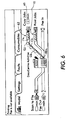
- Figure 5 shows the initial situation in which there are a number of document representations 62 positioned near the copy job status indicator 52, indicating that there are currently a set of documents to be copied.
- the box 65 includes a number "2" indicating that the set of documents will take two minutes to copy.
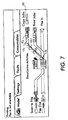
- respective document representations 62a,62b,62c,62d of the set of document representations 62 traverse the connection 57a towards the device 50 indicating that copying is in progress.
- connection 57c that being the connection related to printing jobs is darkened indicating that printing is occurring.
- the document representations 78a and 78b will reach the device 50 and be removed from the connection 57c. Subsequent document representations 78c, 78d 78e move further along the connection 57c indicating the proportion of the printing job that has been completed. Finally, as shown in Figure 13, the print job is completed and all the document representations in the set of document representations 78 have moved along the connection 57c to the device 50.
- this is an animated display and along with the alternate shading of the connecting webs or network stated above, enables the operator to immediately observe and determine the current operation of the machine, the features that are available or are not available on the machine, the capability for concurrent operation of selected features, as well as the degree of completion of the various selected features.
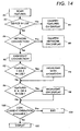
- each device may be configured to automatically generate status signals, thereby allowing each work station 4, connected to the LAN 24, to determine the respective status of each device at any particular time. For each device, if the device is not in use, then the feature is blocked out of the screen display as illustrated at 84. If the device is in use, then, as illustrated in block 86, a decision is made as to whether or not it is part of a network connection. If not, the portion of the display illustrating a network connection is faded or eliminated as shown in block 88. If there is a network connection, as shown in block 90, the connection is highlighted on the display.
- features 1 or 2 are in use as shown in block 92. These typically are features such as a copy jobs operation or print jobs operation where animation on the screen is appropriate to illustrate the concurrency and nearness of completion of the job. If there are such features, as shown in block 94, these features are highlighted on the display with animation. If no such features, then there is a determination if other features are in use as illustrated in decision block 96. If "yes”, then these features are highlighted on the display as shown in block 98. Even if there are no such features there must be a determination whether or not concurrent operation is available as illustrated at block 100. If concurrent operation is available or possible on a given machine, then the display is illuminated or back dropped to suitable display concurrency as shown in block 102. If not, the scanning and displaying is complete and the scan operation is exited as shown in block 104.
- features such as a copy jobs operation or print jobs operation where animation on the screen is appropriate to illustrate the concurrency and nearness of completion of the job. If there are such features, as shown in block 94
Description
- The present invention relates to a user interface, in particular, to a technique of immediate presentation to an operator of the concurrence capability of features in a machine as well as immediate presentation of those features in use, available, and not available for a given machine.
- To meet modern document needs, document systems have been provided with ever expanding feature sets for various local and remote applications such as document copy, document distribution, document storage, and document printing. In the past, to expand feature sets, existing control panels were usually augmented with more menu layers, an increased number of categories of features, and increased numbers of buttons and icons. As a result, end user operators are often confronted with a control panel search task in order to locate and access the particular set of features and electronic dialogs needed for a particular job.
- This has only aggravated job set up complexity for operators. The problem is further intensified when multifunctional features such as fax, print, store, and distribute are required. In these situations, users and operators are often confused on the availability of features and proper selection and combination of features to achieve a given job objective.
- U.S. Pat. No. 5,450,571, assigned to the same assignee as the present invention, discloses a dialog filtering process for a printing system to filter out non-selectable print programming selections. U.S. Pat. No. 5,513,126, assigned to the same assignee as the present invention, discloses a network having selectively accessible recipient prioritized communication channel profiles. In particular, a sender can automatically distribute information to a receiver on a network using devices and communication channels defined in a receiver profile. In addition, US-A-5604860 discloses a method of customizing and storing an interface control for a machine by entering an interface control customizing mode. This provides access to a library of control features for selecting a set of control features for use on a given machine and for arranging the set of control features in a given configuration on a scaled representation of an interface control. The set of control features and given configuration are referenced with a given identifier whereby upon accessing the identifier the set of control features and given configuration are provided on the interface control display. U.S. Serial No. 08/541,547 (D/95418) filed October 10, 1995 discloses a method a using customized interface control panels.
- A difficulty with the aforementioned systems, however, is that they are relatively complicated. For example, U.S. Pat. No. 5,450,571, deals with print queues and providing common electronic job tickets with inter-client protocol and client-server protocol formats including providing printer user interface mask files for each printer. Or they deal with set up, storing and retrieving of customized control panels as disclosed in U.S. Pat. No. 5,513,126 are concerned with communication channel profiles for sending and receiving information over a network.
- A further difficulty is that prior art systems do not account for and simplify for the operator the high degree of automation, networking, interdependency, remote operation, concurrency, faxing, scanning, printing, and traditional copier functionality of existing machines. It would be desirable, therefore, to present to the user an immediate indication of the status and capability of a given machine. That is, it would be desirable to give the operator an immediate and easily recognizable indication of the ability of the machine for concurrent operation of features as well as the current use and capability of network connection.
- It is an object of the present invention, therefore, to provide a new and improved user interface that mimics machine activities as the activities occur and provides timing information, functional sequences, and capabilities of a given machine in its network environment. It is still another object of the present invention to immediately present to an operator the concurrence capability of features in a machine as well as immediate presentation of those features in use, available, and not available for a given machine. Other advantages of the present invention will become apparent as the following description proceeds, and the features characterizing the invention will be pointed out with particularity in the claims annexed to and forming a part of this specification.
- In accordance with the present invention, a method of providing immediate status indicators of an imaging device to an operator, the imaging device being connected to a network defining an imaging system and including a user interface with display screen providing a plurality of feature selections, comprises the steps of:
- providing at the user interface display screen a display of imaging device features in use,
- showing connecting channels on the display screen indicating connection of the imaging device to other devices on the network, and
- displaying at the user interface an indicator of imaging device features available for operation.
- The present invention can provide simultaneous status and capability indicators of an imaging device to an operator by displaying at the user interface display screen an indicator of imaging device features available for operation as well as a display of imaging device features not available for operation. There may also be provided a display of imaging device features in use by animating the display screen and there are displayed connecting channels indicating connection of the imaging device to other devices on the network. Finally, there may be presented to the operator a manifestation of the capability of concurrent feature operation of the imaging device.
- For a better understanding of the present invention, reference may be made to the accompanying drawings wherein the same reference numerals have been applied to like parts and wherein:-
- Figure 1 is an illustration of a system environment incorporating the present invention;
- Figures 2, 3 and 4 are representations of various screen displays portrayed to an operator in accordance with the present invention;
- Figures 5-9 illustrate a display of a copier job in progress in accordance with the present invention;
- Figure 10-13 illustrate a printing job in progress in accordance with the present invention; and,
- Figure 14 is a flow chart illustrating the immediate presentation to an operator of the concurrence capability of features in a machine as well as immediate presentation of those features in use, available, and not available for a given machine in accordance with the present invention.
- While the present invention will hereinafter be described in connection with a preferred embodiment thereof, it will be understood that it is not intended to limit the invention to that embodiment. On the contrary, it is intended to cover all alternatives, modifications, and equivalents, as may be included within the scope of the invention as defined in the appended claims.
- Referring now to the drawings and in particular to Figure 1, an exemplary multimedia device information system or
network 2 including work station 4, enables users to communicate in a transparent and device independent manner.Multimedia system 2 can be implemented using a variety of hardware platforms and includes devices for input including scanner ordigital copier 5, keyboard 6, pointing device or mouse 7, microphone 8, andvideo camera 9. - The system further has devices for output including
display terminal 10,printer 11, andspeakers 12. Input/output (I/O) devices includefacsimile 13, file server 14, andtelephone 15. Server 14 is configured central to or remote from work station 4 with public, shared and/or private data storage that is differentiated by user access rights. The server 14 includesrelational database system 17,network administration system 18, mail system 19 (e.g. e-mail, voice mail) and data storage andretrieval system 20, and can be physically configured using optical drives, hard drives, floppy drives and/or tape drives. Therelational database system 17 provides systems with fast query and retrieval of data. - Work station 4 operates in a collaborative environment, where users at different Work stations 4 can work together in real time to process and distribute public, shared or private information existing in different forms. (Public data is defined herein as data accessible by anyone, shared data is defined as data accessible by a limited number of users and private data is data uniquely accessible by a single user.) Work station 4 can exist in a distributed or centralized environment. In either environment Work station 4 is connected to other systems and devices through local area network (LAN) 24,
gateway 25, and/ormodem 26. In distributed systems, a number of Work stations extend distributed processing and storage capabilities to each other, by providing for example redundant storage or a single mounting of a unique application. - Work station 4 includes an object oriented user interface (UI) 40 that uses icons and windows to represent various data objects and user applications such as a display illustrating an office desktop metaphor employing various abstractions of a typical office environment. User interfaces using windows and icons having an object oriented methodology to present metaphors for maintaining data, navigating through various user spaces and presenting abstract computer concepts are well known.
- This example of the invention consists of a small icon like machine mimic with radiating activity vectors or branches. The small machine icon is centrally positioned relative to its feature extension. This puts emphasis where it should be and illustrates the multifaceted, multi tasking, and concurrent activities the system engages in. It also relieves any contention problem by showing system job entry points, times, and feature priorities, e.g. scanning is available while printing.
- The model is a metaphor for various products increasing learning-comprehension, and serves as an archetypal logo for related systems graphics, icons, instructional material, and systems collateral. It is a model graphic suitable for a "Touch Me" introductory frame, tutoring the novice user. Programmed Copy-, Scan-, and Fax Out Jobs display anticipated completion time, advising the user when to pick up a job. It provides a walk-up user with information when a job is going to start. The model is visually related to network diagrams, printed circuit boards, and electronic chip design.
- This model could be used as a Tutorial Walk-Up screen that would be dynamic in nature, but not necessarily functional. Another alternative is a model that is very functional, showing the system in totality, that makes useful comments on what is currently happening, what is going to happen, and where access points are to get your job done, e.g. scanning while printing. The model also could highlight paper trays being used, their status, etc.
- A dynamic display in accordance with the present invention provides immediate status and capability indicators of an imaging device. The indicators include visual prompts to an operator of imaging device features available for operation and of imaging device features not available for operation. The use of animation provides a prompt of device features already in use or operation. Shown, are connecting channels between displayed devices suggesting network connections and capability. In addition, presented to the operator is a manifestation of the capability of concurrent feature operation of the imaging device. That is, those device features that can be operated concurrently are prompted to the operator by a visual dynamic.
- With reference to Figures 2, 3 and 4, there is illustrated a dynamic tutorial of machine status. As shown, there is an
imaging device representation 50 which generally indicates the devices to which the work station 4 is attached to via theLAN 24. This may therefore represent a single imaging device (not shown) capable of performing many functions or alternatively it may represent a number of devices such as theprinter 11, thescanner 5, thefacsimile 13, or the like. Theimaging device representation 50 will hereinafter be referred to simply as thedevice 50 whether it represents single or multiple devices. - In this example, the
device 50 is interconnected to a copyjob status indicator 52, a printjob status indicator 54, and fax injob indicator 56A via a web of interconnections ornetwork 57. Similarly, afiles status indicator 58,device indicator 60, and fax out job indicator 56B are shown connected to thedevice 50 by a web configuration or anetwork 61. - The darkened connection 57A of the
web 57 indicates a current operation of thedevice 50 in the copy job mode. A not shown phantom designation of a connector would however indicate the respective function as not being currently available ondevice 50. The document designations 53 and 55 illustrate the movement of documents to thedevice 50, as will be explained in more detail below. - Figure 2 illustrates an activity diagram whilst Figure 3 illustrates the status of
device 50 in more detail. In particular,document representations 62 illustrate a set of documents to be copied, whilebox 65 illustrates two minutes for a job completion. As the job nears completion, selecteddocuments 62 will be illustrated as traversing the connection 57A toward thedevice 50 as will be explained below. When the job progresses, the time to completion illustrated will be commensurate with the percentage of documents that have accumulated at thedevice 50. Similarly, there is a fax out display at 68 to illustrate the time to completion of a fax job being sent out fromdevice 50 if the device includes such a feature. - In Figure 4, channel or
web segment 74 can be lightened or faded to indicate "not in use" and thechannel 72 is highlighted or darkened to illustrate that a print job is now in process. Also the web orchannel 76 can be highlighted or shaded to indicate that a scan to file is taking place and that it is taking place concurrently with the print job operation. Thedisplay 70 illustrates the time to completion of the scan to file portion of the job. It should be noted that it is merely a design choice to use any form of shading, highlighting, cross hatching, phantom display, or any other screen technique to illustrate machine states. These states include various features and options such as feature availability, current feature use, the capability of concurrent use of features, the unavailability of features, and progressive or animated display. - The sequence of the copy job operation is further illustrated with reference to Figures 5-9. In this case, the
connections - It will also be noted that an
additional feature indicator 79 indicates that the fax feature is not currently available. - Figure 5 shows the initial situation in which there are a number of
document representations 62 positioned near the copyjob status indicator 52, indicating that there are currently a set of documents to be copied. Thebox 65 includes a number "2" indicating that the set of documents will take two minutes to copy. There are also (Figure 6) a set ofdocument representations 78 adjacent theprint jobs indicator 54 indicating a number of documents in a print queue. In this case, however, theconnection 57a is darkened indicating copying is currently occurring, whilstconnection 57c is lightened indicating that printing will occur in due course. - As shown in Figure 6,
respective document representations document representations 62 traverse theconnection 57a towards thedevice 50 indicating that copying is in progress. - As copying progresses, as shown in Figure 7, the number of document representations on the
connection 57a will decrease in proportion to the amount of copying completed. Thus, as shown,document representation 62a has disappeared whilstdocument representations connection 57a towards thedevice 50. Furthermore, the time indication in thebox 65 has also been reduced indicating the amount of time left for copying to be completed. This procedure continues in Figure 8 withfurther document representations 62 being transferred to thedevice 50. The number in thebox 65 is also further reduced. - Finally, in Figure 9, the copy job is completed and all the
document representations 62 have now been removed from theconnection 57a and a "0" is included in thebox 65 indicating that the copy job is completed. - With the copy job completed, it is now possible for the
device 50 to commence with the printing job, as shown in Figure 10. Accordingly, theconnection 57c, that being the connection related to printing jobs is darkened indicating that printing is occurring. - As shown in Figure 11, as printing commences, various document representations 78a,78b,78c move along the
connection 57c towards thedevice 50. This indicates that printing is in progress. - As shown in Figure 12, as printing continues, the document representations 78a and 78b will reach the
device 50 and be removed from theconnection 57c. Subsequent document representations 78c, 78d 78e move further along theconnection 57c indicating the proportion of the printing job that has been completed. Finally, as shown in Figure 13, the print job is completed and all the document representations in the set ofdocument representations 78 have moved along theconnection 57c to thedevice 50. - It should be understood that this is an animated display and along with the alternate shading of the connecting webs or network stated above, enables the operator to immediately observe and determine the current operation of the machine, the features that are available or are not available on the machine, the capability for concurrent operation of selected features, as well as the degree of completion of the various selected features.
- These features are illustrated with reference to the flow chart of Figure 14. In particular, the various features are scanned as shown in
block 80 to determine the status of the device, as shown inblock 82. In order to achieve the scanning process, it is necessary for the respective work station 4 to generate a poling signal requesting status information. This will be transferred via theLAN 24 to each respective device shown. Each device will then generate a signal indicating the current device status which will be returned via theLAN 24 to the respective work station 4. The work station 4 decodes the signals to determine the device status. - It will however be realised that each device may be configured to automatically generate status signals, thereby allowing each work station 4, connected to the
LAN 24, to determine the respective status of each device at any particular time. For each device, if the device is not in use, then the feature is blocked out of the screen display as illustrated at 84. If the device is in use, then, as illustrated inblock 86, a decision is made as to whether or not it is part of a network connection. If not, the portion of the display illustrating a network connection is faded or eliminated as shown inblock 88. If there is a network connection, as shown inblock 90, the connection is highlighted on the display. - Next there is a determination whether or not selected features such as
features block 92. These typically are features such as a copy jobs operation or print jobs operation where animation on the screen is appropriate to illustrate the concurrency and nearness of completion of the job. If there are such features, as shown inblock 94, these features are highlighted on the display with animation. If no such features, then there is a determination if other features are in use as illustrated indecision block 96. If "yes", then these features are highlighted on the display as shown inblock 98. Even if there are no such features there must be a determination whether or not concurrent operation is available as illustrated atblock 100. If concurrent operation is available or possible on a given machine, then the display is illuminated or back dropped to suitable display concurrency as shown inblock 102. If not, the scanning and displaying is complete and the scan operation is exited as shown inblock 104.
Claims (8)
- A method of providing immediate status indicators of an imaging device to an operator, the imaging device being connected to a network defining an imaging system and including a user interface with display screen providing a plurality of feature selections, the method comprising the steps of:providing at the user interface display screen a display of imaging device features in use,showing connecting channels on the display screen indicating connection of the imaging device to other devices on the network, anddisplaying at the user interface an indicator of imaging device features available for operation.
- A method according to claim 1, further comprising displaying at the user interface display screen an indicator of imaging system features available for operation.
- The method of claim 1 or claim 2, including the step of presenting to the operator a display of the capability of concurrent feature operation of the imaging device.
- The method of claim 1 or claim 2, including the step of presenting to the operator a manifestation of the capability of concurrent feature operation of the imaging system using visually linking indicators of features capable of concurrent operation.
- A method according to claim 3 or claim 4, wherein the features capable of concurrent operation are printing and scanning operations or printing and facsimile operations.
- The method of any of the preceding claims, including the step of providing a display of features not available to the imaging system.
- The method of any of the preceding claims, wherein the step of providing at the user interface display screen a display of imaging device features in use includes the step of animating the display screen.
- The method of any of the preceding claims, wherein the devices include printers and facsimile devices.
Applications Claiming Priority (2)
| Application Number | Priority Date | Filing Date | Title |
|---|---|---|---|
| US929519 | 1992-08-14 | ||
| US08/929,519 US5987535A (en) | 1997-09-15 | 1997-09-15 | User interface providing immediate status and capability indicators of an imaging system on a network by displaying channel connections, features in use, availability, and current operations |
Publications (3)
| Publication Number | Publication Date |
|---|---|
| EP0902582A2 EP0902582A2 (en) | 1999-03-17 |
| EP0902582A3 EP0902582A3 (en) | 2000-01-19 |
| EP0902582B1 true EP0902582B1 (en) | 2006-09-13 |
Family
ID=25457987
Family Applications (1)
| Application Number | Title | Priority Date | Filing Date |
|---|---|---|---|
| EP98307359A Expired - Lifetime EP0902582B1 (en) | 1997-09-15 | 1998-09-11 | User interface with immediate indicators of concurrence, in use, available, and not available features |
Country Status (4)
| Country | Link |
|---|---|
| US (1) | US5987535A (en) |
| EP (1) | EP0902582B1 (en) |
| JP (1) | JPH11165456A (en) |
| DE (1) | DE69835862T2 (en) |
Families Citing this family (40)
| Publication number | Priority date | Publication date | Assignee | Title |
|---|---|---|---|---|
| US7088460B2 (en) * | 1997-09-26 | 2006-08-08 | Minolta Co., Ltd. | Image forming apparatus having a display changeable in color according to operational mode |
| US6854000B2 (en) * | 1997-12-27 | 2005-02-08 | Canon Kabushiki Kaisha | Image forming apparatus and control method for the same |
| DE69933976T2 (en) * | 1998-06-09 | 2007-05-03 | Canon K.K. | A method, data processing apparatus, system and memory unit for enabling direct communication between an image reader and an image output device |
| US6396518B1 (en) * | 1998-08-07 | 2002-05-28 | Hewlett-Packard Company | Appliance and method of using same having a send capability for stored data |
| US6466231B1 (en) | 1998-08-07 | 2002-10-15 | Hewlett-Packard Company | Appliance and method of using same for capturing images |
| US6639687B1 (en) * | 1998-09-08 | 2003-10-28 | International Business Machines Corporation | Progress indicator for multiple actions |
| US6281860B1 (en) * | 1998-09-30 | 2001-08-28 | International Business Machines Corporation | Cues for status information |
| US6240467B1 (en) * | 1998-10-07 | 2001-05-29 | International Business Machines Corporation | Input/output operation request handling in a multi-host system |
| JP2000163176A (en) * | 1998-11-25 | 2000-06-16 | Canon Inc | Peripheral unit, peripheral unit control method, peripheral unit control system and storage medium storing peripheral unit control program |
| US6850995B1 (en) * | 1999-01-25 | 2005-02-01 | Canon Kabushiki Kaisha | Control unit selectively connected with a first bus and a second bus for controlling a displaying process in parallel with a scanning process |
| US6782426B1 (en) * | 1999-04-09 | 2004-08-24 | Canon Kabushiki Kaisha | Shared device control method and server-client system |
| JP4428755B2 (en) * | 1999-04-30 | 2010-03-10 | キヤノン株式会社 | Data processing apparatus, data processing method, and storage medium storing computer-readable program |
| JP3569159B2 (en) * | 1999-06-22 | 2004-09-22 | シャープ株式会社 | Image generation device |
| US6628194B1 (en) * | 1999-08-31 | 2003-09-30 | At&T Wireless Services, Inc. | Filtered in-box for voice mail, e-mail, pages, web-based information, and faxes |
| JP2001236156A (en) * | 2000-02-24 | 2001-08-31 | Nec Corp | Responding method to user instruction of information processor, recording medium and information processor |
| EP1130480B1 (en) | 2000-02-29 | 2014-03-26 | Sharp Kabushiki Kaisha | Display control device for a digital image forming apparatus |
| JP3558950B2 (en) | 2000-03-14 | 2004-08-25 | シャープ株式会社 | Information transmission device |
| US6970266B2 (en) * | 2001-01-23 | 2005-11-29 | Xerox Corporation | Fault notes user interface for a printing system |
| US20020184361A1 (en) * | 2001-05-16 | 2002-12-05 | Guy Eden | System and method for discovering available network components |
| US7020702B2 (en) * | 2001-09-20 | 2006-03-28 | Lexmark International, Inc. | Method and apparatus to obtain real-time status information from a networked device |
| US20030088793A1 (en) * | 2001-11-06 | 2003-05-08 | Parry Travis J. | Managing customized menus across multiple imaging devices |
| US6898645B2 (en) * | 2002-04-17 | 2005-05-24 | Canon Kabushiki Kaisha | Dynamic generation of a user interface based on automatic device detection |
| US7511861B2 (en) * | 2002-08-30 | 2009-03-31 | Hewlett-Packard Development Company, L.P. | Multi-page facsimile method and device |
| US20040181367A1 (en) * | 2003-03-11 | 2004-09-16 | Nguyen Minh H. | Diagnostic display |
| US7489417B2 (en) | 2003-09-30 | 2009-02-10 | Toshiba Corporation | USB print |
| US7492472B2 (en) * | 2003-10-30 | 2009-02-17 | Xerox Corporation | Multimedia communications/collaboration hub |
| US7962364B2 (en) * | 2003-10-30 | 2011-06-14 | Xerox Corporation | Multimedia communications/collaboration hub |
| US20050275877A1 (en) * | 2004-06-12 | 2005-12-15 | Harpreet Singh | System and method for intelligent queuing of documents for processing thereof |
| JP2008219173A (en) * | 2007-02-28 | 2008-09-18 | Brother Ind Ltd | Multi-functional peripheral |
| US8159702B2 (en) * | 2007-07-17 | 2012-04-17 | Xerox Corporation | Printer driver, apparatus and methods for controlling a printer from a devmode data structure |
| US8223364B2 (en) * | 2007-07-17 | 2012-07-17 | Xerox Corporation | Printer driver, apparatus and methods for conrolling a printer from a devmode data structure |
| US20090024950A1 (en) * | 2007-07-17 | 2009-01-22 | Xerox Corporation | Printer Driver Interface and Methods |
| US8159701B2 (en) * | 2007-07-17 | 2012-04-17 | Xerox Corporation | Printer driver, apparatus and methods for conrolling a printer from a devmode data structure |
| US8456666B2 (en) * | 2007-07-17 | 2013-06-04 | Xerox Corporation | Printer driver interface and methods |
| US8792118B2 (en) | 2007-09-26 | 2014-07-29 | Ringcentral Inc. | User interfaces and methods to provision electronic facsimiles |
| US8600391B2 (en) | 2008-11-24 | 2013-12-03 | Ringcentral, Inc. | Call management for location-aware mobile devices |
| US8275110B2 (en) | 2007-09-28 | 2012-09-25 | Ringcentral, Inc. | Active call filtering, screening and dispatching |
| US8670545B2 (en) | 2007-09-28 | 2014-03-11 | Ringcentral, Inc. | Inbound call identification and management |
| US8780383B2 (en) | 2008-11-25 | 2014-07-15 | Ringcentral, Inc. | Authenticated facsimile transmission from mobile devices |
| WO2010062981A2 (en) | 2008-11-26 | 2010-06-03 | Ringcentral, Inc. | Centralized status server for call management of location-aware mobile devices |
Family Cites Families (12)
| Publication number | Priority date | Publication date | Assignee | Title |
|---|---|---|---|---|
| CA2068102C (en) * | 1991-08-29 | 1996-10-01 | Steven V. Rosekrans | Dialog filtering |
| JP3057835B2 (en) * | 1991-09-09 | 2000-07-04 | 日本電気株式会社 | Hardware revision management device |
| JP2773519B2 (en) * | 1992-02-28 | 1998-07-09 | 富士ゼロックス株式会社 | Image processing system |
| US5576946A (en) * | 1993-09-30 | 1996-11-19 | Fluid Air, Inc. | Icon based process design and control system |
| US5513126A (en) * | 1993-10-04 | 1996-04-30 | Xerox Corporation | Network having selectively accessible recipient prioritized communication channel profiles |
| US5548722A (en) * | 1993-10-14 | 1996-08-20 | Apple Computer, Inc. | User-centric system for choosing networked services |
| US5613213A (en) * | 1994-03-31 | 1997-03-18 | Motorola, Inc. | Determining and displaying available services for a communication unit |
| DE69517853T2 (en) * | 1994-04-19 | 2000-11-30 | Canon Kk | Network system to which several image processing devices are connected |
| JPH07311729A (en) * | 1994-05-16 | 1995-11-28 | Ricoh Co Ltd | Information processing system |
| JP3342225B2 (en) * | 1995-03-29 | 2002-11-05 | ブラザー工業株式会社 | Facsimile function display method, facsimile function acquisition device, facsimile device, and facsimile system |
| JP3639022B2 (en) * | 1995-12-08 | 2005-04-13 | 株式会社東芝 | Composite image forming apparatus |
| US5751965A (en) * | 1996-03-21 | 1998-05-12 | Cabletron System, Inc. | Network connection status monitor and display |
-
1997
- 1997-09-15 US US08/929,519 patent/US5987535A/en not_active Expired - Lifetime
-
1998
- 1998-09-08 JP JP25419798A patent/JPH11165456A/en not_active Withdrawn
- 1998-09-11 DE DE69835862T patent/DE69835862T2/en not_active Expired - Lifetime
- 1998-09-11 EP EP98307359A patent/EP0902582B1/en not_active Expired - Lifetime
Also Published As
| Publication number | Publication date |
|---|---|
| DE69835862T2 (en) | 2007-04-12 |
| EP0902582A2 (en) | 1999-03-17 |
| DE69835862D1 (en) | 2006-10-26 |
| EP0902582A3 (en) | 2000-01-19 |
| JPH11165456A (en) | 1999-06-22 |
| US5987535A (en) | 1999-11-16 |
Similar Documents
| Publication | Publication Date | Title |
|---|---|---|
| EP0902582B1 (en) | User interface with immediate indicators of concurrence, in use, available, and not available features | |
| US5630079A (en) | Document job key to tailor multifunctional user interfaces | |
| US5604860A (en) | Feature library and stored customized control interfaces | |
| US5726883A (en) | Method of customizing control interfaces for devices on a network | |
| US5579087A (en) | Constructing a multi-segment print job from multiple local or remote sources using a network interface | |
| US5657461A (en) | User interface for defining and automatically transmitting data according to preferred communication channels | |
| US5689642A (en) | Recipient prioritized communication channel profiles | |
| JP3584124B2 (en) | Data processing method | |
| US7545525B2 (en) | Input-output apparatus selecting method for network system | |
| US6697090B1 (en) | Device controller, method of displaying user interface, and recording medium in which computer program for displaying user interface is recorded | |
| US4965676A (en) | Facsimile remote diagnostic system | |
| JPH09128181A (en) | Method for retrieval of interface control with reference to user display | |
| US20030058266A1 (en) | Hot linked help | |
| US20040051912A1 (en) | Facsimile manager | |
| JP3767089B2 (en) | Recording medium recording input / output device designation program in network, and input / output device designation system and method in network | |
| US20080126963A1 (en) | User terminal to manage driver and network port and method of controlling the same | |
| US7844910B2 (en) | Linking information making device, linking information making method, recording medium having recorded a linking information making program, and document processing system therewith | |
| EP0772114B1 (en) | Apparatus and method for programming a job ticket in a document processing system | |
| JP4179569B2 (en) | Recording medium recording input / output device designation program in network, and input / output device designation system and method in network | |
| EP0917006A2 (en) | Input/output model for multifunction user interfaces | |
| US6964024B2 (en) | Operator-defined visitation sequence of client user interface controls | |
| JPH1028196A (en) | Job state display device | |
| JPH09179711A (en) | Method for preserving customized interface control from user display | |
| JPH10268998A (en) | Interface controlling method | |
| JP2001051817A (en) | Data output control system |
Legal Events
| Date | Code | Title | Description |
|---|---|---|---|
| PUAI | Public reference made under article 153(3) epc to a published international application that has entered the european phase |
Free format text: ORIGINAL CODE: 0009012 |
|
| AK | Designated contracting states |
Kind code of ref document: A2 Designated state(s): DE FR GB |
|
| AX | Request for extension of the european patent |
Free format text: AL;LT;LV;MK;RO;SI |
|
| PUAL | Search report despatched |
Free format text: ORIGINAL CODE: 0009013 |
|
| AK | Designated contracting states |
Kind code of ref document: A3 Designated state(s): AT BE CH CY DE DK ES FI FR GB GR IE IT LI LU MC NL PT SE |
|
| AX | Request for extension of the european patent |
Free format text: AL;LT;LV;MK;RO;SI |
|
| 17P | Request for examination filed |
Effective date: 20000719 |
|
| AKX | Designation fees paid |
Free format text: DE FR GB |
|
| GRAP | Despatch of communication of intention to grant a patent |
Free format text: ORIGINAL CODE: EPIDOSNIGR1 |
|
| GRAS | Grant fee paid |
Free format text: ORIGINAL CODE: EPIDOSNIGR3 |
|
| GRAA | (expected) grant |
Free format text: ORIGINAL CODE: 0009210 |
|
| AK | Designated contracting states |
Kind code of ref document: B1 Designated state(s): DE FR GB |
|
| REG | Reference to a national code |
Ref country code: GB Ref legal event code: FG4D |
|
| RIN1 | Information on inventor provided before grant (corrected) |
Inventor name: MARTIN, ANDREW T. Inventor name: BARRETT, MICHAEL W. Inventor name: KNODT, RUEDIGER W. |
|
| REF | Corresponds to: |
Ref document number: 69835862 Country of ref document: DE Date of ref document: 20061026 Kind code of ref document: P |
|
| ET | Fr: translation filed | ||
| PLBE | No opposition filed within time limit |
Free format text: ORIGINAL CODE: 0009261 |
|
| STAA | Information on the status of an ep patent application or granted ep patent |
Free format text: STATUS: NO OPPOSITION FILED WITHIN TIME LIMIT |
|
| 26N | No opposition filed |
Effective date: 20070614 |
|
| REG | Reference to a national code |
Ref country code: FR Ref legal event code: PLFP Year of fee payment: 18 |
|
| PGFP | Annual fee paid to national office [announced via postgrant information from national office to epo] |
Ref country code: DE Payment date: 20150820 Year of fee payment: 18 Ref country code: GB Payment date: 20150825 Year of fee payment: 18 |
|
| PGFP | Annual fee paid to national office [announced via postgrant information from national office to epo] |
Ref country code: FR Payment date: 20150824 Year of fee payment: 18 |
|
| REG | Reference to a national code |
Ref country code: DE Ref legal event code: R119 Ref document number: 69835862 Country of ref document: DE |
|
| GBPC | Gb: european patent ceased through non-payment of renewal fee |
Effective date: 20160911 |
|
| REG | Reference to a national code |
Ref country code: FR Ref legal event code: ST Effective date: 20170531 |
|
| PG25 | Lapsed in a contracting state [announced via postgrant information from national office to epo] |
Ref country code: GB Free format text: LAPSE BECAUSE OF NON-PAYMENT OF DUE FEES Effective date: 20160911 Ref country code: DE Free format text: LAPSE BECAUSE OF NON-PAYMENT OF DUE FEES Effective date: 20170401 Ref country code: FR Free format text: LAPSE BECAUSE OF NON-PAYMENT OF DUE FEES Effective date: 20160930 |