EP0902370B1 - Doppelte Plattenspeichersteuerungen - Google Patents
Doppelte Plattenspeichersteuerungen Download PDFInfo
- Publication number
- EP0902370B1 EP0902370B1 EP98116656A EP98116656A EP0902370B1 EP 0902370 B1 EP0902370 B1 EP 0902370B1 EP 98116656 A EP98116656 A EP 98116656A EP 98116656 A EP98116656 A EP 98116656A EP 0902370 B1 EP0902370 B1 EP 0902370B1
- Authority
- EP
- European Patent Office
- Prior art keywords
- controller
- write
- write data
- time
- primary
- Prior art date
- Legal status (The legal status is an assumption and is not a legal conclusion. Google has not performed a legal analysis and makes no representation as to the accuracy of the status listed.)
- Expired - Lifetime
Links
Images


Classifications
-
- G—PHYSICS
- G06—COMPUTING; CALCULATING OR COUNTING
- G06F—ELECTRIC DIGITAL DATA PROCESSING
- G06F11/00—Error detection; Error correction; Monitoring
- G06F11/07—Responding to the occurrence of a fault, e.g. fault tolerance
- G06F11/16—Error detection or correction of the data by redundancy in hardware
- G06F11/20—Error detection or correction of the data by redundancy in hardware using active fault-masking, e.g. by switching out faulty elements or by switching in spare elements
- G06F11/2053—Error detection or correction of the data by redundancy in hardware using active fault-masking, e.g. by switching out faulty elements or by switching in spare elements where persistent mass storage functionality or persistent mass storage control functionality is redundant
- G06F11/2056—Error detection or correction of the data by redundancy in hardware using active fault-masking, e.g. by switching out faulty elements or by switching in spare elements where persistent mass storage functionality or persistent mass storage control functionality is redundant by mirroring
- G06F11/2064—Error detection or correction of the data by redundancy in hardware using active fault-masking, e.g. by switching out faulty elements or by switching in spare elements where persistent mass storage functionality or persistent mass storage control functionality is redundant by mirroring while ensuring consistency
-
- G—PHYSICS
- G06—COMPUTING; CALCULATING OR COUNTING
- G06F—ELECTRIC DIGITAL DATA PROCESSING
- G06F11/00—Error detection; Error correction; Monitoring
- G06F11/07—Responding to the occurrence of a fault, e.g. fault tolerance
- G06F11/16—Error detection or correction of the data by redundancy in hardware
- G06F11/20—Error detection or correction of the data by redundancy in hardware using active fault-masking, e.g. by switching out faulty elements or by switching in spare elements
- G06F11/2053—Error detection or correction of the data by redundancy in hardware using active fault-masking, e.g. by switching out faulty elements or by switching in spare elements where persistent mass storage functionality or persistent mass storage control functionality is redundant
- G06F11/2056—Error detection or correction of the data by redundancy in hardware using active fault-masking, e.g. by switching out faulty elements or by switching in spare elements where persistent mass storage functionality or persistent mass storage control functionality is redundant by mirroring
- G06F11/2071—Error detection or correction of the data by redundancy in hardware using active fault-masking, e.g. by switching out faulty elements or by switching in spare elements where persistent mass storage functionality or persistent mass storage control functionality is redundant by mirroring using a plurality of controllers
- G06F11/2074—Asynchronous techniques
-
- G—PHYSICS
- G06—COMPUTING; CALCULATING OR COUNTING
- G06F—ELECTRIC DIGITAL DATA PROCESSING
- G06F2201/00—Indexing scheme relating to error detection, to error correction, and to monitoring
- G06F2201/82—Solving problems relating to consistency
Definitions
- the present invention relates to dual writing of data to be executed through the effect of two controllers.
- the present invention is effective in the case that a long distance exists between the two controllers so that a delay takes place in transferring data between the controllers.
- the European Patent Publication No. 0671686A1 has disclosed a technique of doing dual writing through the effect of controllers spaced from each other by a long distance.
- one controller guarantees data on a disk therein if the other controller is broken by a disaster such as an earthquake.
- the technique disclosed in EP-0671686A1 is arranged so that a primary controller directly receives write data from a host computer, transfers the received write data to a secondary controller located in a remote place, and reports completion of receipt of the write data to a host computer.
- This is a quite excellent method from a viewpoint of data security because the data to be stored in the primary controller is completely equivalent to the data to be stored in the secondary controller.
- a longer distance existing between two controllers makes a data transfer time between the controllers far larger. This method therefore has difficulty on performance to be solved if one controller is far away from the other controller.
- the European Patent Application Publication No. 0672985A1 also has disclosed a technique of doing dual writing on disks loaded in two controllers far away from each other.
- the technique disclosed in EP-0672985A1 is arranged so that a primary controller directly receives write data from a primary host computer, immediately after receipt of the write data, reports completion of the receipt of the write data to the primary host computer.
- a copy of the write data received by the primary controller is read out to the primary host computer.
- a time stamp is given to the write data received from the primary host computer for the first time. The time stamp indicates a time when a request for writing the write data is issued.
- the write time is passed to the primary host computer as well. Then, the primary host computer sends the copy of the write data and the write time to a secondary host computer.
- the secondary host computer When the secondary host computer receives the write data and the write time, information such as the write data is written on the disk for the control purpose. Further, the write data is written on the disk on the secondary side in the sequence of the write time by referring to the time given to each write data record.
- the secondary host computer performs the foregoing procedure, because it is not desirable to leave the intermediate results of the transactions normally used by an online system. For example, considering a transaction of transferring a bank deposit from a bank account A to another bank account B, though the deposit is withdrawn from the bank account A, the state of having transferred no corresponding deposit to the bank account B is not left. This means that no intermediate result of the transaction is left. Normally, the recovery unit is a transaction on the online system. Hence, leaving the intermediate result of the transaction is a quite significant obstacle.
- the disks on which data is dually written contain a disk for storing a database such as account information and a disk for storing a journal where an update history of the transaction is left. If the host computer is failed, a recovery program is started to analyze the journal so that the update result of the unfinished transaction is returned to the state before the execution and no intermediate result of the transaction is left.
- the write data written on the disk loaded in the secondary controller is effective only in the cases such as when the primary controller for storing the latest write data is broken. The secondary controller does not store the latest write data but can guarantee the write data up to a certain time.
- the host computer yields an equivalent state to the failed state at a time when the write data is guaranteed.
- the disk for storing the journal loaded in the secondary controller and the disk for storing the database, the similar process to the recovery to be executed when the host computer is failed is executed so that the intermediate result of the transaction may not be left.
- the disk controller contains a non-volatile cache memory and provides a write-after technique, that is, a technique of writing the write data received from the host computer onto a non-volatile cache memory and reporting the completion of the write to the host computer.
- the non-volatile cache memory is highly reliable, so that the data may be sufficiently guaranteed by storing the write data in the cache.
- the technique disclosed in the EP-0672985A1 is arranged to suppress the degrade of the performance though some data is lost even if a distance between the controllers is expanded. Further, it does not leave the intermediate result of the transaction.
- the technique disclosed in the EP-0672985A1 is arranged so that the primary host computer reads out data and transfers the data to the secondary host computer. Hence, unlike the EP-0671686A1 arranged to directly transfer the write data between the controllers, this technique needs one more data transfers. Further, an I/O process to and from a storage medium such as an MT is required to be done.
- US-A-5 155 845 relates to a redundant disk array system for mirroring data between a primary and a secondary disk controller. Write data are exchanged between the controllers, but no time stamps are given to the individual write requests.
- US-A-5 504 861 discloses a system and method for remote data duplexing. Each write request is prefixed with a header including an operation time stamp. The header data are stored as journal data in the duplexing system.
- US-A-5 577 222 discloses another system for asynchronously duplexing remote data.
- the host computer gives a write time to each write data record when it issues a request for write to a primary controller.
- the primary controller receives the write data from the host computer, it reports the completion of the receipt to the host computer. Then, the primary controller sends the write data records and the write times to the secondary controller. At this time, the primary controller operates to send the write data records to the secondary controller in the sequence of the writing times.
- the secondary controller operates to store the write data received from the primary controller onto a non-volatile cache memory. This makes it possible to guarantee the write data without any I/O process of control information to and from disks.
- the secondary controller can guarantee the write data up to a certain time by referring to the received write time. This makes it possible to leave no intermediate result of the transaction.
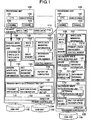
- Fig. 1 illustrates a general configuration of the first embodiment.
- the system of the first embodiment is configured to have one or more processing units 100, one primary controller 104, one or more disk units 105 connected to the primary controller 104, one secondary controller 109, and one or more disk units 105 connected to the secondary controller 109.
- the processing unit 100 is composed of a CPU 101, a main storage 102, and a channel 103.
- the primary controller 104 contains a control memory 107 and a cache memory 108.
- the control memory 107 and the cache memory 108 are non-volatilized. For enhancing the reliability, each memory may be dualized.
- the cache memory 108 or the control memory 107 is composed of a semiconductor memory.
- the primary controller 104 operates to transfer data between the processing unit 100 and the disk unit 105. Further, according to the present invention, the primary controller 104 provides a function of transferring data with the secondary controller 109. Or, the primary controller 104 contains one or more directors 106, each of which may operate to transfer data between the processing unit 100 and the disk unit 205 and between the secondary controller 109 and the director 106 itself.
- the internal arrangement of the secondary controller 109 is similar to that of the primary controller 104.
- the write data managing information 113 corresponding to the write data record 112 is created on the control memory 107.
- the processing unit 100 When the processing unit 100 issues a request for write 110 to the primary controller 104, the processing unit 100 operates to give a write time 111 to the write data record 112.
- the write time 111 represents a time when the request for write 110 is issued.
- the primary controller 104 and the secondary controller 109 can recognize the sequence of the requests for write 110 issued by the processing unit 100 by referring to this write time 111. If two or more processing units 100 are provided, the write time 111 is defined by using the common clocks among the processing units 100, so that the primary controller 104 and the secondary controller 108 can recognize the sequence of the requests for write 110 issued by different processing units 110.
- Fig. 2 illustrates a composition of write data managing information 113.
- a disk to be specified when the processing unit 100 issues the request for write 110 is referred to as a logical disk.
- a logical disk ID 120 indicates a number of a logical disk indicated by the processing unit 100 so that the corresponding write data is written on the logical disk and is contained in the request for write 110.
- This invention does not require the one-to-one correspondence between the logical disk recognized by the processing unit 100 and the disk unit 105 (physical disk).
- the logical disk may be defined over two or more disk units 105.
- the logical disk may contain redundant data and thus employ a RAID (Redundant Array of Inexpensive Disks) arrangement.
- a numeral 121 denotes a write address that is information (for example, information such as an area of 1 Mbyte starting from a head of the logical disk) for indicating an address inside of a logical disk where the corresponding write data is to be written and is contained in the request for write 110.
- a numeral 122 denotes a write data length that represents a length of the corresponding write data and is contained in the request for write 110. These pieces of information are all contained in the normal request for write 110.
- a numeral 123 denotes a write data pointer that is a pointer to the corresponding write data 112 in the cache memory 108.
- the write time 111 has been already described above.
- the write time 111 to be given to the request for write 110 is a feature of the invention.
- a numeral 124 denotes a necessity bit that indicates that the write data is required to be transferred to the secondary controller. (Herein, the bit 124 is referred to as a necessity bit 124.)
- This necessity bit 124 is information that represents transfer of the corresponding write data 112 to the secondary controller 109.
- a secondary logical disk number 114 is located to correspond to the logical disk of the primary controller 104 and contains the numbers of the secondary logical disk of the corresponding logical disk, which are paired for dual writing, that is, a number of the secondary controller 109 for loading the secondary logical disk and a logical disk number located in the secondary controller 109 of the secondary logical disk.
- a null value for indicating invalidity is put into the logical disk.
- the control memory 107 of the secondary controller 109 contains the write data managing information 113 as well.
- the information may have the same format as the write data managing information 113 in the primary controller 104, in which the necessity bit 124 is constantly off.
- the control memory 107 of the secondary controller 109 contains a primary logical disk number.
- the present information is located to correspond to the logical disk of the secondary controller 109 and contains the numbers of the primary logical disk of the corresponding logical disk, which are paired for dual writing, that is, the number of the primary controller 104 for loading the primary logical disk and the logical disk number in the primary controller 104 of the primary logical disk.
- a null value for indicating invalidity is put into the logical disk.
- the primary controller 104 provides a primary write data receiving unit 130, which is started when it receives the request for write 110 from the processing unit 100.
- the received write data 112 is stored in the cache memory 108 (step 131).
- the primary write data receiving unit 130 operates to secure the write data managing information 113 inside of the control memory 108 for processing this request for write (step 132).
- the information such as the write time 111 contained in the request for write is stored in the secured write data managing information 113 for setting a write data pointer 123 and the necessity bit 124 (step 133).
- the completion of the request for write 110 is reported to the processing unit 100 (step 134).
- the foregoing processing makes it possible to do a quick response because no access is required for the disk unit 105.
- the process of writing the write data 112 onto the disk unit 105 is executed by the primary controller 104 at a later stage. This operation is executed by the normal controller. Hence, it is not described in detail.
- the primary controller 104 has a primary write data transmitting unit 140, which provides a function of transmitting the write data 112 to the secondary controller 109.
- the write data record 112 at the earliest write time, included in the write data managing information 113 in which the necessity bit 124 is set is transmitted to the secondary controller 109 having a pair for dual writing located therein by referring to the corresponding secondary logical disk number 114.
- the length of the write data 112 and the address inside of the secondary logical disk where the write data is to be written are specified by referring to the information contained in the write data managing information 113 (step 141).
- the primary write data transmitting unit 140 waits for a report on the completion from the secondary controller 109 (step 142). When the report on the completion is given back, the necessity bit 124 is set off (step 143). Then, the operation goes back to the step 140 at which the next write data to be transmitted is tried to be found.
- the secondary controller 109 has a secondary write data receiving unit 160, which is started when the write data 112 is received from the primary controller 104.
- the processing content of the secondary write data receiving unit 160 is similar to that of the primary write data receiving unit 140 except that the setting of the write data managing information 113 does not contain a process of setting the necessity bit 124 (step 161). After the write data 112 from the primary controller 104 is written in the cache 108, the completion of the write is reported to the primary controller 104.
- the secondary controller 109 has a secondary write data destaging unit 170, which provides a function of writing the write data 112 to the disk unit 105.
- some write data records 112 included in the write data managing information 113 are determined to be written in the disk unit 105 in the sequence from the earliest write time.
- a necessary calculation is executed to determine the disk unit 105 where the write data records are to be written and the write address. The method of calculation is not described in detail, because it is used for the normal RAID (step 171).
- two or more requests for writing the write data 112 to the disk unit 105 are issued to the disk unit 105 in parallel (step 172).
- the secondary write data destaging unit 170 waits for a report on the completion of the request (step 173). After the reports on the completion of all the requests are received, the operation goes back to the step 171 at which the next write data 113 to be destaged to the next disk unit 105 is tried to be found.
- the transmitting sequence of the write data 113 from the primary controller 104 to the secondary controller 109 is the sequence of the write time 111.
- the secondary controller 109 enables to generate a state that it can hold all the write data records 113 on or before a reference time and cannot hold all the write data records 113 after the reference time. This operation makes it possible for the secondary controller 109 to do a recovering process without leaving any intermediate result of a transaction if the primary controller 104 is broken.
- the control information such as the write data 112 and the write time 111 is held in a non-volatile semiconductor memory such as the cache memory 108 and the control memory 107. Hence, no large overhead is burdened on the performance.
- aforementioned process may not provide sufficient performance because the transfer of the write data 112 from the primary controller 104 to the secondary controller 109 is serialized.
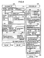
- Fig. 4 illustrates the process executed in the case of transferring the write data 112 from the primary controller 104 to the secondary controller 109 in parallel.
- a primary write data transmitting unit a300, a primary reference time transmitting unit 170, a secondary reference time receiving unit 180, a secondary write data destaging unit a310, and a primary fail-time data scrapping unit 190 are changed from the configuration in which the transfer is serialized.
- the primary write data transmitting unit a300 waits for a report on the completion of each write from the secondary controller 109 (step 302). After all the reports are given back, the necessity bit 124 included in the corresponding write data managing information 113 is set off (step 303). Then, the operation goes back to the step 150 at which the next write data 112 to be transmitted is tried to be found.
- the execution of the parallel transfer of the write data records 112 may make each write time 111 of the write data records 112 be out of the sequence.
- the write data 112 to be destaged is made to have the earlier write time 111 than the reference time corresponding to the earliest write time 111 among the write data included in the write data managing information 113 where the necessity bit 124 is set on, which are all contained in the primary controller 104.
- the write data records 112 having the write time 111 on or before the reference time should not be destaged. If the primary controller 104 is broken, the write data records 112 have to be broken without being destaged.
- the primary reference time transmitting unit 170 provides a function of transmitting the destageable reference time to the secondary controller 109.
- the reference time is the earliest write time 111 included in the write data managing information 113 where the necessity bit 124 is set on.
- the secondary reference time receiving unit 180 operates to store the reference time received from the primary controller 104 in the control memory 108 as a destageable time 185.
- Fig. 4 illustrates a processing flow of the secondary write data destaging unit a310 executed in the case of transmitting the write data records 112 from the primary controller 104 to the secondary controller 109 in parallel.
- the condition for selecting the write data 112 to be destaged includes a condition for determining if the write time 111 is on or before the destageable time 185 (step 311).
- the primary fail-time data scrapping unit 197 provides a function of scrapping the write data 112 having the write time 111 later than the destageable time 185 when the primary controller 104 is broken (step 191).
- Fig. 5 illustrates a system configuration according to a second embodiment of the present invention.
- the difference between the first and the second embodiments is the number of the primary controllers 104.
- the system of the first embodiment is configured to have one primary controller 104 and one secondary controller 109, while the system of the second embodiment is configured to have two or more primary controllers 104 and one secondary controller 209.
- the provision of two or more primary controllers 104 makes the write time 111 of the write data 112 received from one primary controller 104 shifted from that received from another primary controller 104 on the side of the secondary controller 109.
- the latest write time 111 of the write data 112 received from one primary controller 104 (for example, the primary controller a) is assumed as a time a, while the latest write time 111 of the write data 112 received from another primary controller 104 (for example, the primary controller b) is assumed as a time b. In this assumption, if the time a is earlier than the time b, the primary controller b may hold the write data 113 of the time later than the time a but earlier than the time b.
- the write data record 112 of the write time 111 on or before the time a is made to be the write data record 112 to be destaged on the secondary controller 109.
- the control memory 108 of the secondary controller 109 stores a write enable time 500 to the primary controller.
- the write enable time 500 is the information existing in each primary controller 104 and is the latest write time 111 received from the corresponding primary controller 104. As mentioned above, therefore, of these write enable times 500, the write data record 112 of the write time 111 on or before the reference time, that is, the earliest time corresponds to the write data record 112 to be destaged onto the secondary controller 109.
- the description will be oriented to the content of each processing unit in the case of transferring the write data 112 from one primary controller 104 to the secondary controller 109 in parallel. It goes without saying that the present embodiment is effective in the case of serializing the transfer of the write data 112 from one primary controller 104 to the secondary controller 109.
- each processing unit included in the primary controller 104 is likewise to the processing flow (the process shown in Fig. 3) executed in the case of transferring the write data 112 in parallel in the first embodiment.
- the description will be oriented to the processing flow of a secondary write data destaging unit b510.
- the description will be oriented to the difference between the processing flow of the secondary write data destaging unit 520 included in the second embodiment and the processing flow of the secondary write data destaging unit 170 included in the first embodiment.
- the content of the process executed in the secondary write data receiving unit 510 according to the second embodiment is executed to check if the corresponding write time 111 is on or before all the write enable times 500 and select the write data record 112 for meeting the condition (step 511). Except this process, the processing flow of the secondary write data destaging unit b510 included in the second embodiment is likewise to the processing flow of the secondary write data destaging unit 170 included in the first embodiment.
- the secondary reference time receiving unit b520 operates to set the reference time received from the primary controller 104 as a write enable time 500 of the primary controller 104 having transmitted the reference time.
- the write data 112 to be scrapped by the primary fail-time data scrapping unit b530 corresponds to the write data 112 that does not meet the condition that the corresponding write time 111 is on or before the write enable times 500 of all the primary controllers (step 531).
- Fig. 6 illustrates a general system configuration according to the third embodiment.
- the difference between the second and the third embodiments is also the numbers of the primary controllers 104 and the secondary controllers 109.
- the system of the third embodiment is configured to have two or more primary controllers 104 and one or more secondary controllers 109. In this case, each pair of the primary controller 104 and the secondary controller 109 is not required to be connected.
- a master secondary controller 700 provides a function of determining the reference time used for selecting the write data record 112 to be destaged.
- a data transfer path is connected between the master controller 700 and the other secondary controllers 109. If the data transfer path is failed, it is impossible to keep the reference times used for selecting the write data records 112 to be destaged common among the secondary controllers 109. Hence, multiplexing the data transfer path is preferable.
- the master secondary controller 700 provides a function of determining the reference time used for selecting the write data record 112 to be destaged. Without providing the specific secondary controller 109 with the function of determining the reference time, the method for distributing the function among the secondary controllers 109 (for example, the method wherein the secondary controllers 109 alternately determine the reference time) may be employed for implementing the present invention.
- the control memory 109 of the master secondary controller 700 stores a write time 701 of the secondary controller.
- This write time 701 is the information corresponding to the secondary controllers 109 containing the master secondary controller 700.
- the write time 701 of each secondary controller corresponds to the information periodically received by the master secondary controller 700 from each secondary controller 109 at the earliest time (the reference time on which the secondary controller 109 selects the secondary controller 109 in the second embodiment) among all the primary controller write enable times 500 contained in the secondary controller 109.
- the master write time 702 is a reference time on which each secondary controller 109 selects the write data.
- the master write time 702 is set by the process wherein the master secondary controller 700 refers to all the secondary controller write times 701 at a proper period and selects the earliest time. All the write data records 112 having the write times 111 on or before the selected time are contained in the secondary controller 109. Hence, by guaranteeing the write data 112 that meet this condition and scrapping all the write data 112 that do not meet it, it is possible to erase the intermediate result of the transaction.
- each processing unit included in the primary controller 104 is substantially similar to that of the second embodiment. It goes without saying that the primary reference time transmitting unit 170 provides a function of transmitting a reference time to each secondary controller 109 for transmitting the write data 112.
- the reference time to be transmitted corresponds to the earliest write time 111 contained in the write data managing information 113 in which the necessity bit 124 of each write data record 112 corresponding to the secondary controller 109 for transmitting the reference time is set on.
- the secondary controller 109 contains a secondary write time transmitting unit 710, a secondary write data destaging unit c720, and a primary fail-time data scrapping point c
- the master secondary controller 700 contains a master secondary write time receiving unit 711, a master write time calculating unit 712, and a master secondary write time transmitting unit 713.
- the secondary write time transmitting unit 710 operates to transmit the earliest time 180 included in all the primary controller write enable times 500 stored in the primary controller 109 to the master secondary write time receiving unit 711 included in the master secondary controller 700 at a proper period.
- the secondary write time transmitting unit 710 included in the secondary controller 109 except the master secondary controller 700 makes use of a data transfer path between the secondary controllers 109.
- the secondary write time transmitting unit 710 of the master secondary controller 700 makes use of communicating means provided in the master secondary controller 700.
- the master secondary write time receiving unit 711 operates to set the time received from the secondary write time transmitting unit 710 to the secondary controller write time 701 corresponding to the secondary controller 109 having transmitted the time.
- the master write time calculating unit 712 operates to refer to all the secondary controller write times 701, select the earliest time, and then set the time as the master write time 702.
- the master secondary write time transmitting unit 713 operates to transmit the time set as the master write time 702 at a proper period in response to the requests issued from the secondary write data destaging unit 720 and the primary fail-time data scrapping unit 730 included in each secondary controller 109.
- the secondary controller 109 rather than the master secondary controller 700 makes use of the data transfer path between the secondary controllers 109.
- the master secondary write time transmitting unit 713 makes use of communicating means provided in the master secondary controller 700.
- the different respect of the secondary write data destaging unit 720 from that of the second embodiment is that when selecting the write data 112 to be destaged, the secondary write data destaging unit 720 operates to receive the reference time from the master secondary write time transmitting unit 713 and select the write data 112 with the earlier write time 111 than the reference time as the write data to be destaged (step 721).
- the different respect of the primary fail-time data scrapping unit c730 from that of the second embodiment is that when selecting the write data 112 to be scrapped from the cache memory 107, the primary fail-time data scrapping unit c730 operates to receive the reference time from the master secondary write time transmitting unit 713 and select the write data 112 except all the write data 112 with the earlier write time 111 than the reference time as the write data to be scrapped (step 731).
- the master controller 700 is arranged to receive the information required for calculating the reference time from the secondary controller 109. In place, it may be arranged to receive the information from the primary controller 104 as shown in Fig. 7.
- the control memory 108 of the master secondary controller 700 stores a master primary controller write time 800.
- the write time 800 corresponds to the primary controller 104.
- the write time 800 is set as follows.
- the master secondary controller 700 receives the earliest write time 111 included in all the write data managing information 113 containing the necessity bits 124 being set at a proper period and sets it as the write time 800 inside of the primary controller 109.
- the master secondary controller 700 operates to refer to all the primary controller write times 701, select the earliest time and set it as the master write time 702 at a proper period.
- the reference time for the destaging or the data scrapping is the master write time 702.
Claims (4)
- Computersystem mit:einer Verarbeitungseinheit (100);einer ersten Steuereinheit (104), die an die Verarbeitungseinheit angeschlossen ist und einen ersten Cache-Speicher (108) aufweist;einer ersten Platteneinheit (105), die an die erste Steuereinheit (104) angeschlossen ist;einer zweiten Steuereinheit (109), die an die erste Steuereinheit (104) angeschlossen ist und einen zweiten Cache-Speicher (108) aufweist;einer zweiten Platteneinheit (105), die an die zweite Steuereinheit angeschlossen ist,wobei
die Verarbeitungseinheit (100) dazu ausgelegt ist, eine Schreibanfrage (110), die Schreibdaten (112) und eine Schreibzeit (111) enthält, an die erste Steuereinheit (104) auszugeben,
die erste Steuereinheit (104) dazu ausgelegt ist, die Schreibdaten (112) in dem ersten Cache-Speicher (108) zu speichern, die Erledigung der Schreibanfrage (110) an die Verarbeitungseinheit (100) zu berichten, die in dem ersten Cache-Speicher (108) in der ersten Platteneinheit (105) gespeicherten Schreibdaten (112) zu speichern, und mehrere Paare der Schreibdaten (112) und der Schreibzeiten (111) an die zweite Steuereinheit (109) zu übertragen,
die zweite Steuereinheit (109) dazu ausgelegt ist, die Schreibdaten (112) und die von der ersten Steuereinheit (104) übertragene Schreibzeit (111) in dem zweiten Cache-Speicher (108) zu speichern, und einen Bericht über die Erledigung der Speicherung in dem zweiten Cache-Speicher an die erste Steuereinheit (104) zu übertragen,
die erste Steuereinheit (104) dazu ausgelegt ist, eine Zurückspeicherungszeit (185) an die zweite Steuereinheit (109) zu übertragen, wobei die Zurückspeicherungszeit auf Grundlage des von der zweiten Steuereinheit (109) empfangenen Berichts festgelegt ist, und
die zweite Steuereinheit (109) dazu ausgelegt ist, die Schreibdaten (112) in der zweiten Platteneinheit (105) zu speichern, die in dem zweiten Cache-Speicher (108) gespeichert sind und eine Schreibzeit (111) aufweisen, die früher ist als die Zurückspeicherungszeit (185). - Computersystem nach Anspruch 1, wobei der erste und der zweite Cache-Speicher (108) nicht-flüchtig sind.
- Computersystem nach Anspruch 1, ferner mit einer weiteren Verarbeitungseinheit, wobei beide Verarbeitungseinheiten (100) einen gemeinsamen Takt aufweisen.
- Computersystem nach Anspruch 1, wobei die zweite Steuereinheit (109) dazu ausgelegt ist, die Schreibdaten auszusondern, die in dem zweiten Cache-Speicher (108) gespeichert sind und eine Schreibzeit (111) aufweisen, die später ist als die Zurückspeicherungszeit (185), falls die erste Steuereinheit (104) ausfällt.
Priority Applications (1)
| Application Number | Priority Date | Filing Date | Title |
|---|---|---|---|
| EP07010734A EP1843249B1 (de) | 1997-09-12 | 1998-09-03 | Speichersteuerung für asynchrone Datenspiegelung |
Applications Claiming Priority (2)
| Application Number | Priority Date | Filing Date | Title |
|---|---|---|---|
| JP24817797A JP3414218B2 (ja) | 1997-09-12 | 1997-09-12 | 記憶制御装置 |
| JP248177/97 | 1997-09-12 |
Related Child Applications (1)
| Application Number | Title | Priority Date | Filing Date |
|---|---|---|---|
| EP07010734A Division EP1843249B1 (de) | 1997-09-12 | 1998-09-03 | Speichersteuerung für asynchrone Datenspiegelung |
Publications (3)
| Publication Number | Publication Date |
|---|---|
| EP0902370A2 EP0902370A2 (de) | 1999-03-17 |
| EP0902370A3 EP0902370A3 (de) | 2006-05-03 |
| EP0902370B1 true EP0902370B1 (de) | 2007-12-26 |
Family
ID=17174358
Family Applications (2)
| Application Number | Title | Priority Date | Filing Date |
|---|---|---|---|
| EP07010734A Expired - Lifetime EP1843249B1 (de) | 1997-09-12 | 1998-09-03 | Speichersteuerung für asynchrone Datenspiegelung |
| EP98116656A Expired - Lifetime EP0902370B1 (de) | 1997-09-12 | 1998-09-03 | Doppelte Plattenspeichersteuerungen |
Family Applications Before (1)
| Application Number | Title | Priority Date | Filing Date |
|---|---|---|---|
| EP07010734A Expired - Lifetime EP1843249B1 (de) | 1997-09-12 | 1998-09-03 | Speichersteuerung für asynchrone Datenspiegelung |
Country Status (4)
| Country | Link |
|---|---|
| US (5) | US6408370B2 (de) |
| EP (2) | EP1843249B1 (de) |
| JP (1) | JP3414218B2 (de) |
| DE (2) | DE69841768D1 (de) |
Cited By (4)
| Publication number | Priority date | Publication date | Assignee | Title |
|---|---|---|---|---|
| CN101520713A (zh) * | 2008-02-27 | 2009-09-02 | 株式会社日立制作所 | 存储系统、复制方法以及正侧的存储装置 |
| US7673107B2 (en) | 2004-10-27 | 2010-03-02 | Hitachi, Ltd. | Storage system and storage control device |
| US7725445B2 (en) | 2003-06-27 | 2010-05-25 | Hitachi, Ltd. | Data replication among storage systems |
| US8234471B2 (en) | 2003-06-27 | 2012-07-31 | Hitachi, Ltd. | Remote copy method and remote copy system |
Families Citing this family (88)
| Publication number | Priority date | Publication date | Assignee | Title |
|---|---|---|---|---|
| US6665781B2 (en) | 2000-10-17 | 2003-12-16 | Hitachi, Ltd. | Method and apparatus for data duplexing in storage unit system |
| JP3414218B2 (ja) * | 1997-09-12 | 2003-06-09 | 株式会社日立製作所 | 記憶制御装置 |
| JP4252139B2 (ja) * | 1998-12-16 | 2009-04-08 | 株式会社日立製作所 | 記憶装置システム |
| JP2000305856A (ja) | 1999-04-26 | 2000-11-02 | Hitachi Ltd | ディスクサブシステム及びこれらの統合システム |
| US6539462B1 (en) | 1999-07-12 | 2003-03-25 | Hitachi Data Systems Corporation | Remote data copy using a prospective suspend command |
| JP3743975B2 (ja) * | 1999-09-27 | 2006-02-08 | 株式会社日立製作所 | 記憶装置システム |
| US6757797B1 (en) | 1999-09-30 | 2004-06-29 | Fujitsu Limited | Copying method between logical disks, disk-storage system and its storage medium |
| US6684306B1 (en) | 1999-12-16 | 2004-01-27 | Hitachi, Ltd. | Data backup in presence of pending hazard |
| JP2001184267A (ja) * | 1999-12-27 | 2001-07-06 | Hitachi Ltd | 記憶サブシステム |
| JP4434407B2 (ja) * | 2000-01-28 | 2010-03-17 | 株式会社日立製作所 | サブシステム及びこれらの統合システム |
| JP4044717B2 (ja) * | 2000-03-31 | 2008-02-06 | 株式会社日立製作所 | 記憶サブシステムのデータ二重化方法及びデータ二重化システム |
| US6859824B1 (en) | 2000-06-30 | 2005-02-22 | Hitachi, Ltd. | Storage system connected to a data network with data integrity |
| JP2002189570A (ja) | 2000-12-20 | 2002-07-05 | Hitachi Ltd | 記憶システムの二重化方法および記憶システム |
| US6862659B1 (en) * | 2001-01-04 | 2005-03-01 | Emc Corporation | Utilizing disk cache as part of distributed cache |
| US7152096B2 (en) | 2001-08-06 | 2006-12-19 | Hitachi, Ltd. | High performance storage access environment |
| US7103727B2 (en) * | 2002-07-30 | 2006-09-05 | Hitachi, Ltd. | Storage system for multi-site remote copy |
| JP2004171437A (ja) * | 2002-11-22 | 2004-06-17 | Fujitsu Ltd | ストレージ制御装置及びその制御方法 |
| CN1723631B (zh) * | 2003-01-07 | 2015-06-03 | 三星电子株式会社 | 控制混合自动重复请求移动通信系统中的输出缓冲器的设备和方法 |
| JP4301849B2 (ja) | 2003-03-31 | 2009-07-22 | 株式会社日立製作所 | 情報処理方法及びその実施システム並びにその処理プログラム並びにディザスタリカバリ方法およびシステム並びにその処理を実施する記憶装置およびその制御処理方法 |
| US7120825B2 (en) * | 2003-06-06 | 2006-10-10 | Hewlett-Packard Development Company, L.P. | Adaptive batch sizing for asynchronous data redundancy |
| US7152182B2 (en) * | 2003-06-06 | 2006-12-19 | Hewlett-Packard Development Company, L.P. | Data redundancy system and method |
| US7178055B2 (en) * | 2003-06-06 | 2007-02-13 | Hewlett-Packard Development Company, L.P. | Method and system for ensuring data consistency after a failover event in a redundant data storage system |
| US7165187B2 (en) * | 2003-06-06 | 2007-01-16 | Hewlett-Packard Development Company, L.P. | Batch based distributed data redundancy |
| JP4374953B2 (ja) | 2003-09-09 | 2009-12-02 | 株式会社日立製作所 | データ処理システム |
| US7130975B2 (en) | 2003-06-27 | 2006-10-31 | Hitachi, Ltd. | Data processing system |
| JP4090400B2 (ja) * | 2003-07-24 | 2008-05-28 | 株式会社日立製作所 | ストレージシステム |
| US7219201B2 (en) * | 2003-09-17 | 2007-05-15 | Hitachi, Ltd. | Remote storage disk control device and method for controlling the same |
| US7152183B2 (en) * | 2003-11-20 | 2006-12-19 | Hitachi, Ltd. | Method and apparatus for volume replication management at planned and unplanned link down |
| US7724599B2 (en) * | 2003-12-03 | 2010-05-25 | Hitachi, Ltd. | Remote copy system |
| US7085788B2 (en) * | 2003-12-03 | 2006-08-01 | Hitachi, Ltd. | Remote copy system configured to receive both a write request including a write time and a write request not including a write time. |
| US7437389B2 (en) * | 2004-03-10 | 2008-10-14 | Hitachi, Ltd. | Remote copy system |
| JP4434857B2 (ja) * | 2003-12-04 | 2010-03-17 | 株式会社日立製作所 | リモートコピーシステム及びシステム |
| JP4412989B2 (ja) | 2003-12-15 | 2010-02-10 | 株式会社日立製作所 | 複数の記憶システムを有するデータ処理システム |
| JP4282464B2 (ja) | 2003-12-17 | 2009-06-24 | 株式会社日立製作所 | リモートコピーシステム |
| US7139887B2 (en) * | 2003-12-31 | 2006-11-21 | Veritas Operating Corporation | Coordinated storage management operations in replication environment |
| US7600087B2 (en) | 2004-01-15 | 2009-10-06 | Hitachi, Ltd. | Distributed remote copy system |
| JP4477370B2 (ja) * | 2004-01-30 | 2010-06-09 | 株式会社日立製作所 | データ処理システム |
| JP2005235040A (ja) * | 2004-02-23 | 2005-09-02 | Hottolink:Kk | データ管理方法及びデータ管理システム |
| US7039785B2 (en) | 2004-02-24 | 2006-05-02 | Hitachi, Ltd. | Method and apparatus for increasing an amount of memory on demand when monitoring remote mirroring performance |
| US7421549B2 (en) | 2004-03-02 | 2008-09-02 | Hitachi, Ltd. | Method and apparatus of remote copy for multiple storage subsystems |
| JP2005258850A (ja) * | 2004-03-12 | 2005-09-22 | Hitachi Ltd | 計算機システム |
| JP4452533B2 (ja) | 2004-03-19 | 2010-04-21 | 株式会社日立製作所 | システムおよび記憶装置システム |
| JP4382602B2 (ja) * | 2004-04-23 | 2009-12-16 | 株式会社日立製作所 | リモートコピーシステム |
| JP4715286B2 (ja) | 2004-05-11 | 2011-07-06 | 株式会社日立製作所 | 計算機システムおよび計算機システムの制御方法 |
| GB0410540D0 (en) * | 2004-05-12 | 2004-06-16 | Ibm | Write set boundary management for heterogeneous storage controllers in support of asynchronous update of secondary storage |
| JP4563725B2 (ja) | 2004-05-17 | 2010-10-13 | 株式会社日立製作所 | 計算機システム |
| JP4477950B2 (ja) * | 2004-07-07 | 2010-06-09 | 株式会社日立製作所 | リモートコピーシステム及び記憶装置システム |
| JP4519563B2 (ja) * | 2004-08-04 | 2010-08-04 | 株式会社日立製作所 | 記憶システム及びデータ処理システム |
| JP4508798B2 (ja) * | 2004-08-09 | 2010-07-21 | 株式会社日立製作所 | ストレージリモートコピー方式 |
| JP4915775B2 (ja) | 2006-03-28 | 2012-04-11 | 株式会社日立製作所 | ストレージシステム及びストレージシステムのリモートコピー制御方法 |
| US7330861B2 (en) | 2004-09-10 | 2008-02-12 | Hitachi, Ltd. | Remote copying system and method of controlling remote copying |
| JP4377790B2 (ja) | 2004-09-30 | 2009-12-02 | 株式会社日立製作所 | リモートコピーシステムおよびリモートコピー方法 |
| US7519851B2 (en) * | 2005-02-08 | 2009-04-14 | Hitachi, Ltd. | Apparatus for replicating volumes between heterogenous storage systems |
| JP4728031B2 (ja) | 2005-04-15 | 2011-07-20 | 株式会社日立製作所 | リモートコピーペアの移行を行うシステム |
| US7404051B2 (en) * | 2005-04-18 | 2008-07-22 | Hitachi, Ltd. | Method for replicating snapshot volumes between storage systems |
| JP5036158B2 (ja) | 2005-10-05 | 2012-09-26 | 株式会社日立製作所 | 情報処理システム及び情報処理システムの制御方法 |
| JP4790377B2 (ja) | 2005-11-07 | 2011-10-12 | 株式会社日立製作所 | ストレージサブシステムのボリューム複製方法 |
| JP2007200085A (ja) * | 2006-01-27 | 2007-08-09 | Nec Corp | データ複製システムおよびデータ複製方法 |
| JP5050358B2 (ja) * | 2006-01-27 | 2012-10-17 | 日本電気株式会社 | データ複製システムおよびデータ複製方法 |
| JP4830562B2 (ja) | 2006-03-17 | 2011-12-07 | 株式会社日立製作所 | 情報処理システムのデータ入出力方法及び情報処理システム |
| US7640395B2 (en) * | 2006-03-30 | 2009-12-29 | Intel Corporation | Maintaining write ordering in a system |
| US7647525B2 (en) * | 2006-03-31 | 2010-01-12 | Emc Corporation | Resumption of operations following failover in connection with triangular asynchronous replication |
| JP4835249B2 (ja) | 2006-04-26 | 2011-12-14 | 株式会社日立製作所 | ストレージシステム、リモートコピー、その管理方法 |
| JP4833734B2 (ja) | 2006-05-19 | 2011-12-07 | 株式会社日立製作所 | データベースシステム、ストレージ装置、初期コピー方法及びログ適用方法 |
| JP5244332B2 (ja) * | 2006-10-30 | 2013-07-24 | 株式会社日立製作所 | 情報システム、データ転送方法及びデータ保護方法 |
| US9330190B2 (en) * | 2006-12-11 | 2016-05-03 | Swift Creek Systems, Llc | Method and system for providing data handling information for use by a publish/subscribe client |
| JP5052150B2 (ja) | 2007-01-29 | 2012-10-17 | 株式会社日立製作所 | ストレージシステム |
| US20080270546A1 (en) * | 2007-04-30 | 2008-10-30 | Morris Robert P | Methods And Systems For Communicating Task Information |
| JP2008299789A (ja) * | 2007-06-04 | 2008-12-11 | Hitachi Ltd | リモートコピーシステム及びリモートコピーの制御方法 |
| US8066791B2 (en) | 2007-07-20 | 2011-11-29 | Donaldson Company, Inc. | Air cleaner arrangements with internal and external support for cartridge; components; and, methods |
| JP4861286B2 (ja) * | 2007-10-02 | 2012-01-25 | 日本電信電話株式会社 | データバックアップ方法、復元処理装置、プログラム及び記録媒体 |
| JP5401041B2 (ja) | 2008-02-21 | 2014-01-29 | 株式会社日立製作所 | ストレージシステム及びコピー方法 |
| US8255562B2 (en) | 2008-06-30 | 2012-08-28 | International Business Machines Corporation | Adaptive data throttling for storage controllers |
| JP5422147B2 (ja) | 2008-07-08 | 2014-02-19 | 株式会社日立製作所 | リモートコピーシステム及びリモートコピー方法 |
| US20100049927A1 (en) * | 2008-08-21 | 2010-02-25 | International Business Machines Corporation | Enhancement of data mirroring to provide parallel processing of overlapping writes |
| US20100049926A1 (en) * | 2008-08-21 | 2010-02-25 | International Business Machines Corporation | Enhancement of data mirroring to provide parallel processing of overlapping writes |
| JP5486793B2 (ja) | 2008-11-07 | 2014-05-07 | 株式会社日立製作所 | リモートコピー管理システム、方法及び装置 |
| JP4990322B2 (ja) * | 2009-05-13 | 2012-08-01 | 株式会社日立製作所 | データ移動管理装置及び情報処理システム |
| US8850114B2 (en) | 2010-09-07 | 2014-09-30 | Daniel L Rosenband | Storage array controller for flash-based storage devices |
| US8661202B2 (en) | 2010-12-10 | 2014-02-25 | International Business Machines Corporation | Systems and methods for destaging storage tracks from cache |
| DE102011003907A1 (de) | 2011-02-10 | 2012-08-16 | Continental Automotive Gmbh | Abgasturbolader mit gekühltem Turbinengehäuse |
| US8560771B2 (en) | 2011-07-22 | 2013-10-15 | International Business Machines Corporation | Efficient track destage in secondary storage |
| JP5742542B2 (ja) * | 2011-07-25 | 2015-07-01 | 富士通株式会社 | ストレージ装置及びその負荷状態低減方法 |
| CN103914474B (zh) * | 2013-01-05 | 2018-12-28 | 腾讯科技(深圳)有限公司 | 一种数据迁移方法及系统 |
| JP6028850B2 (ja) * | 2013-03-13 | 2016-11-24 | 日本電気株式会社 | データ多重化システム |
| KR102527992B1 (ko) * | 2016-03-14 | 2023-05-03 | 삼성전자주식회사 | 데이터 저장 장치와 이를 포함하는 데이터 처리 시스템 |
| CN110544948A (zh) * | 2019-09-11 | 2019-12-06 | 国网湖南省电力有限公司 | 一种双重化配置的statcom控制保护系统及其调度监控方法 |
| US11256448B2 (en) * | 2019-12-16 | 2022-02-22 | Samsung Electronics Co., Ltd. | Network storage gateway |
Family Cites Families (24)
| Publication number | Priority date | Publication date | Assignee | Title |
|---|---|---|---|---|
| JP2834189B2 (ja) * | 1989-07-05 | 1998-12-09 | 株式会社日立製作所 | 入出力制御方法 |
| US5155845A (en) * | 1990-06-15 | 1992-10-13 | Storage Technology Corporation | Data storage system for providing redundant copies of data on different disk drives |
| US5544347A (en) | 1990-09-24 | 1996-08-06 | Emc Corporation | Data storage system controlled remote data mirroring with respectively maintained data indices |
| JPH04291618A (ja) * | 1991-03-20 | 1992-10-15 | Fujitsu Ltd | 二重化ディスク制御方式 |
| US5555371A (en) * | 1992-12-17 | 1996-09-10 | International Business Machines Corporation | Data backup copying with delayed directory updating and reduced numbers of DASD accesses at a back up site using a log structured array data storage |
| US5577222A (en) * | 1992-12-17 | 1996-11-19 | International Business Machines Corporation | System for asynchronously duplexing remote data by sending DASD data grouped as a unit periodically established by checkpoint based upon the latest time value |
| US5615329A (en) | 1994-02-22 | 1997-03-25 | International Business Machines Corporation | Remote data duplexing |
| KR0128271B1 (ko) | 1994-02-22 | 1998-04-15 | 윌리암 티. 엘리스 | 재해회복을 위한 일관성 그룹 형성방법 및 레코드갱싱의 섀도잉 방법, 주시스템, 원격데이타 섀도잉 시스템과 비동기 원격데이타 복제 시스템 |
| US5504861A (en) * | 1994-02-22 | 1996-04-02 | International Business Machines Corporation | Remote data duplexing |
| JPH07234811A (ja) | 1994-02-25 | 1995-09-05 | Fujitsu Ltd | リモートファイル制御方法 |
| JP2894676B2 (ja) * | 1994-03-21 | 1999-05-24 | インターナショナル・ビジネス・マシーンズ・コーポレイション | 非同期式遠隔コピー・システム及び非同期式遠隔コピー方法 |
| US5692155A (en) * | 1995-04-19 | 1997-11-25 | International Business Machines Corporation | Method and apparatus for suspending multiple duplex pairs during back up processing to insure storage devices remain synchronized in a sequence consistent order |
| US5799141A (en) * | 1995-06-09 | 1998-08-25 | Qualix Group, Inc. | Real-time data protection system and method |
| JP3769775B2 (ja) * | 1995-06-14 | 2006-04-26 | 富士通株式会社 | 分散リンク情報維持方法 |
| JP3020833B2 (ja) | 1995-06-19 | 2000-03-15 | 株式会社東芝 | チェックポイント取得システム |
| US5680640A (en) * | 1995-09-01 | 1997-10-21 | Emc Corporation | System for migrating data by selecting a first or second transfer means based on the status of a data element map initialized to a predetermined state |
| AU7704696A (en) * | 1995-12-01 | 1997-06-27 | British Telecommunications Public Limited Company | Database access |
| JPH09171441A (ja) * | 1995-12-20 | 1997-06-30 | Hitachi Ltd | 二重化記憶装置の記憶一致方法および装置 |
| JPH09212425A (ja) | 1996-02-02 | 1997-08-15 | Nec Eng Ltd | ライトキャシュバックアップ方式 |
| US5870537A (en) * | 1996-03-13 | 1999-02-09 | International Business Machines Corporation | Concurrent switch to shadowed device for storage controller and device errors |
| US5901327A (en) * | 1996-05-28 | 1999-05-04 | Emc Corporation | Bundling of write data from channel commands in a command chain for transmission over a data link between data storage systems for remote data mirroring |
| JPH09325917A (ja) | 1996-06-07 | 1997-12-16 | Hitachi Ltd | 計算機システム |
| US5949970A (en) * | 1997-01-07 | 1999-09-07 | Unisys Corporation | Dual XPCS for disaster recovery |
| JP3414218B2 (ja) * | 1997-09-12 | 2003-06-09 | 株式会社日立製作所 | 記憶制御装置 |
-
1997
- 1997-09-12 JP JP24817797A patent/JP3414218B2/ja not_active Expired - Lifetime
-
1998
- 1998-09-03 DE DE69841768T patent/DE69841768D1/de not_active Expired - Lifetime
- 1998-09-03 EP EP07010734A patent/EP1843249B1/de not_active Expired - Lifetime
- 1998-09-03 DE DE69838898T patent/DE69838898T2/de not_active Expired - Lifetime
- 1998-09-03 EP EP98116656A patent/EP0902370B1/de not_active Expired - Lifetime
- 1998-09-09 US US09/149,666 patent/US6408370B2/en not_active Expired - Lifetime
-
2002
- 2002-05-07 US US10/139,248 patent/US6615332B2/en not_active Expired - Lifetime
-
2003
- 2003-07-09 US US10/614,802 patent/US7216208B2/en not_active Expired - Fee Related
-
2004
- 2004-04-26 US US10/831,138 patent/US7191303B2/en not_active Expired - Fee Related
-
2006
- 2006-10-19 US US11/583,007 patent/US7657707B2/en not_active Expired - Fee Related
Non-Patent Citations (1)
| Title |
|---|
| None * |
Cited By (10)
| Publication number | Priority date | Publication date | Assignee | Title |
|---|---|---|---|---|
| US7725445B2 (en) | 2003-06-27 | 2010-05-25 | Hitachi, Ltd. | Data replication among storage systems |
| US8135671B2 (en) | 2003-06-27 | 2012-03-13 | Hitachi, Ltd. | Data replication among storage systems |
| US8234471B2 (en) | 2003-06-27 | 2012-07-31 | Hitachi, Ltd. | Remote copy method and remote copy system |
| US8239344B2 (en) | 2003-06-27 | 2012-08-07 | Hitachi, Ltd. | Data replication among storage systems |
| US8566284B2 (en) | 2003-06-27 | 2013-10-22 | Hitachi, Ltd. | Data replication among storage systems |
| US8943025B2 (en) | 2003-06-27 | 2015-01-27 | Hitachi, Ltd. | Data replication among storage systems |
| US9058305B2 (en) | 2003-06-27 | 2015-06-16 | Hitachi, Ltd. | Remote copy method and remote copy system |
| US7673107B2 (en) | 2004-10-27 | 2010-03-02 | Hitachi, Ltd. | Storage system and storage control device |
| CN101520713A (zh) * | 2008-02-27 | 2009-09-02 | 株式会社日立制作所 | 存储系统、复制方法以及正侧的存储装置 |
| EP2096529A3 (de) * | 2008-02-27 | 2011-04-06 | Hitachi Ltd. | Speichersystem, Kopierverfahren und Primärspeichervorrichtung |
Also Published As
| Publication number | Publication date |
|---|---|
| US7216208B2 (en) | 2007-05-08 |
| EP1843249A3 (de) | 2008-12-24 |
| EP1843249A2 (de) | 2007-10-10 |
| DE69838898T2 (de) | 2008-08-07 |
| EP0902370A3 (de) | 2006-05-03 |
| US20040088484A1 (en) | 2004-05-06 |
| EP1843249B1 (de) | 2010-07-14 |
| EP0902370A2 (de) | 1999-03-17 |
| US7657707B2 (en) | 2010-02-02 |
| US20010029570A1 (en) | 2001-10-11 |
| US20040199737A1 (en) | 2004-10-07 |
| US7191303B2 (en) | 2007-03-13 |
| DE69841768D1 (de) | 2010-08-26 |
| US20070038833A1 (en) | 2007-02-15 |
| JP3414218B2 (ja) | 2003-06-09 |
| US6615332B2 (en) | 2003-09-02 |
| JPH1185408A (ja) | 1999-03-30 |
| US6408370B2 (en) | 2002-06-18 |
| DE69838898D1 (de) | 2008-02-07 |
| US20020129202A1 (en) | 2002-09-12 |
Similar Documents
| Publication | Publication Date | Title |
|---|---|---|
| EP0902370B1 (de) | Doppelte Plattenspeichersteuerungen | |
| US6606694B2 (en) | Write logging in mirrored disk subsystems | |
| KR0128271B1 (ko) | 재해회복을 위한 일관성 그룹 형성방법 및 레코드갱싱의 섀도잉 방법, 주시스템, 원격데이타 섀도잉 시스템과 비동기 원격데이타 복제 시스템 | |
| US5682513A (en) | Cache queue entry linking for DASD record updates | |
| US7734883B2 (en) | Method, system and program for forming a consistency group | |
| US5504861A (en) | Remote data duplexing | |
| US5615329A (en) | Remote data duplexing | |
| US7188222B2 (en) | Method, system, and program for mirroring data among storage sites | |
| KR100376747B1 (ko) | 데이터 일관성을 유지하는 방법, 시스템 및 프로그램 제조물 | |
| US20050071708A1 (en) | Method, system, and program for recovery from a failure in an asynchronous data copying system | |
| US6510456B1 (en) | Data transfer control method and system, data transfer control program file, and file storage medium | |
| JP3797328B2 (ja) | 記憶制御装置 | |
| JP4531643B2 (ja) | 記憶制御方法、システム及びプログラム | |
| JP3894196B2 (ja) | 記憶制御装置 | |
| JP3894220B2 (ja) | 記憶制御装置 | |
| JP2006236387A (ja) | 記憶制御装置 |
Legal Events
| Date | Code | Title | Description |
|---|---|---|---|
| PUAI | Public reference made under article 153(3) epc to a published international application that has entered the european phase |
Free format text: ORIGINAL CODE: 0009012 |
|
| AK | Designated contracting states |
Kind code of ref document: A2 Designated state(s): AT BE CH CY DE DK ES FI FR GB GR IE IT LI LU MC NL PT SE |
|
| AX | Request for extension of the european patent |
Free format text: AL;LT;LV;MK;RO;SI |
|
| PUAL | Search report despatched |
Free format text: ORIGINAL CODE: 0009013 |
|
| AK | Designated contracting states |
Kind code of ref document: A3 Designated state(s): AT BE CH CY DE DK ES FI FR GB GR IE IT LI LU MC NL PT SE |
|
| AX | Request for extension of the european patent |
Extension state: AL LT LV MK RO SI |
|
| 17P | Request for examination filed |
Effective date: 20060331 |
|
| AKX | Designation fees paid |
Designated state(s): DE FR GB |
|
| GRAP | Despatch of communication of intention to grant a patent |
Free format text: ORIGINAL CODE: EPIDOSNIGR1 |
|
| GRAS | Grant fee paid |
Free format text: ORIGINAL CODE: EPIDOSNIGR3 |
|
| GRAA | (expected) grant |
Free format text: ORIGINAL CODE: 0009210 |
|
| AK | Designated contracting states |
Kind code of ref document: B1 Designated state(s): DE FR GB |
|
| REG | Reference to a national code |
Ref country code: GB Ref legal event code: FG4D |
|
| REF | Corresponds to: |
Ref document number: 69838898 Country of ref document: DE Date of ref document: 20080207 Kind code of ref document: P |
|
| ET | Fr: translation filed | ||
| PLBE | No opposition filed within time limit |
Free format text: ORIGINAL CODE: 0009261 |
|
| STAA | Information on the status of an ep patent application or granted ep patent |
Free format text: STATUS: NO OPPOSITION FILED WITHIN TIME LIMIT |
|
| 26N | No opposition filed |
Effective date: 20080929 |
|
| PGFP | Annual fee paid to national office [announced via postgrant information from national office to epo] |
Ref country code: FR Payment date: 20120926 Year of fee payment: 15 |
|
| REG | Reference to a national code |
Ref country code: FR Ref legal event code: ST Effective date: 20140530 |
|
| PG25 | Lapsed in a contracting state [announced via postgrant information from national office to epo] |
Ref country code: FR Free format text: LAPSE BECAUSE OF NON-PAYMENT OF DUE FEES Effective date: 20130930 |
|
| PGFP | Annual fee paid to national office [announced via postgrant information from national office to epo] |
Ref country code: DE Payment date: 20150825 Year of fee payment: 18 Ref country code: GB Payment date: 20150902 Year of fee payment: 18 |
|
| REG | Reference to a national code |
Ref country code: DE Ref legal event code: R119 Ref document number: 69838898 Country of ref document: DE |
|
| GBPC | Gb: european patent ceased through non-payment of renewal fee |
Effective date: 20160903 |
|
| PG25 | Lapsed in a contracting state [announced via postgrant information from national office to epo] |
Ref country code: GB Free format text: LAPSE BECAUSE OF NON-PAYMENT OF DUE FEES Effective date: 20160903 Ref country code: DE Free format text: LAPSE BECAUSE OF NON-PAYMENT OF DUE FEES Effective date: 20170401 |