EP0901898A1 - Corrugated paper and device as well as process for the manufacture of the corrugated paper - Google Patents
Corrugated paper and device as well as process for the manufacture of the corrugated paper Download PDFInfo
- Publication number
- EP0901898A1 EP0901898A1 EP98117240A EP98117240A EP0901898A1 EP 0901898 A1 EP0901898 A1 EP 0901898A1 EP 98117240 A EP98117240 A EP 98117240A EP 98117240 A EP98117240 A EP 98117240A EP 0901898 A1 EP0901898 A1 EP 0901898A1
- Authority
- EP
- European Patent Office
- Prior art keywords
- profile
- roller
- strip
- curvature
- corrugated
- Prior art date
- Legal status (The legal status is an assumption and is not a legal conclusion. Google has not performed a legal analysis and makes no representation as to the accuracy of the status listed.)
- Granted
Links
Images


Classifications
-
- B—PERFORMING OPERATIONS; TRANSPORTING
- B31—MAKING ARTICLES OF PAPER, CARDBOARD OR MATERIAL WORKED IN A MANNER ANALOGOUS TO PAPER; WORKING PAPER, CARDBOARD OR MATERIAL WORKED IN A MANNER ANALOGOUS TO PAPER
- B31F—MECHANICAL WORKING OR DEFORMATION OF PAPER, CARDBOARD OR MATERIAL WORKED IN A MANNER ANALOGOUS TO PAPER
- B31F1/00—Mechanical deformation without removing material, e.g. in combination with laminating
- B31F1/20—Corrugating; Corrugating combined with laminating to other layers
- B31F1/24—Making webs in which the channel of each corrugation is transverse to the web feed
- B31F1/26—Making webs in which the channel of each corrugation is transverse to the web feed by interengaging toothed cylinders cylinder constructions
- B31F1/28—Making webs in which the channel of each corrugation is transverse to the web feed by interengaging toothed cylinders cylinder constructions combined with uniting the corrugated webs to flat webs ; Making double-faced corrugated cardboard
- B31F1/2845—Details, e.g. provisions for drying, moistening, pressing
- B31F1/2863—Corrugating cylinders; Supporting or positioning means therefor; Drives therefor
Definitions
- the invention relates to an apparatus for manufacturing corrugated cardboard, comprising a first grooved roller and a second grooved roller together forming a corrugated slot, a support roller forming a support slot with the second grooved roller, inlet means to admit a continuous strip to the corrugated slot, in which the continuous strip is deformed into corrugated strip, inlet means to admit a smooth strip at the support slot, in which the strip smooth is supported on the corrugated strip by means of adhesive means, and transport means for transporting the composite tape formed by the approximation of the corrugated strip and the smooth strip, each of the two fluted rollers having a fluted profit on its outer face with profit peaks and profit valleys extending in the direction of the respective axis cooperating for the wavy deformation, vertices of profit and succeeding profit valleys of each fluted roll being linked by profit flanks and profit peaks of each roll fluted, moreover having a greater curvature than that of the valleys of profit from the other grooved roller cooperating with them for
- Devices of this kind are made with fluted rollers of different forms, the profit being determined by the difference and the height of the teeth.
- the paper strip is compressed under pressure and influence of heat between profits of fluted rollers cooperants and then glued with a smooth covering strip. Usually, this is also done under the influence of heat and pressure by through a support routine or compression roller.
- the embossing process itself takes place between the fluted tops or profit vertices of a grooved roller and the base surfaces grooves or respective profit valleys of the other grooved roller. Usually, the flanks do not participate in the embossing process. In constructions like this the difference between the radii of the vertices profit and cooperating profit valleys play an important role.
- the contact between the profile vertices of the second fluted rout and the essentially cylindrical surface of the backing roller takes place in the slot support, i.e. in the contact area between the second roller grooved and the support roller.
- the distance between the axes of the two rollers defined by the contact of the grooved roller and the roller support constantly varies during the rotation of the rollers between a value maximum, when a profile vertex is located near a connecting plane containing the axes of the rollers, and a minimum value, when a valley in profile of the second grooved roller is located in the connection plane containing the axes of the rollers.
- curvature and in particular the curvature apex of the profile tops of the second grooved roller is a factor essential that influences paper damage on the side of the roll support of the smooth strip.
- the increase in the spread creates an increased risk of vibration excitation, because the deviation is also responsible for variations in the distance between the axes of the second roller quirkiness and the support roller, for a simple geometric reason: a increased deviation causes increased variations in radial distance between the axes of the second grooved roller and the support roller.
- the invention aims to arrange an apparatus of the kind as mentioned in preamble so that the vibration excitation is reduced and the risk of marking on the corresponding composite tape as well as fiber damage is reduced.
- the risk of meshing mutual that is to say the risk of a catching of the cooperating teeth of the two fluted rollers should be avoided.
- the vertices of profile of the first fluted roller have a greater curvature than that of profile tops of the second grooved roller and, if desired, the profile valleys of the first fluted roller have less curvature than that of the profile valleys of the second grooved roller.
- the composite strip produced in an apparatus according to the invention can be a single-sided corrugated board to use as it is, for example for wrap cylindrical items.
- the compound tape can also be a preparatory product for two or more sides corrugated board layers.
- corrugated cardboard includes especially bands compounds, which are produced using single strips containing fibers and especially cellulose fibers.
- the composite strip consists of other materials, for example strips of synthetic material, which can in principle be machined for the manufacture of single-sided corrugated compound strips.
- the invention is based on the idea, that an increased vibration excitation and increased charges appear mainly only where the profile ribs of the second grooved roller are in contact under pressure with the backing roller, the corrugated strip and the smooth strip being interspersed.
- crowns more strongly curved of the corrugated strip are formed. These peaks more strongly curved of the corrugated strip have no disadvantage for the respective product. Even if the corresponding compound tape is subsequently machined from double-sided corrugated cardboard (Doubleface), the tops more strongly curved of the corrugated strip are glued to a smooth strip of paper in an essentially flat junction line, where none vibration cannot appear and where thus the influence of the vertex radius is limited.
- the proposal of the invention can be applied indifferently from the question, if the profile vertices of the fluted rollers are bent in arc of a circle or have another form of curvature, for example a form of curvature formed by a combination of several arcs of a circle.
- a curvature of the profile vertices of the arc fluted rollers of circle the idea of the invention is presented so that the vertices of profile of the first grooved roller have a radius of curvature smaller than that of the profile tops of the second grooved roller.
- the valleys of profile of the two fluted rollers can also be curved in an arc in a circle, especially when the profile vertices are also curved in an arc; in this case, the profile valleys of the first roller fluted have a greater radius of curvature than that of the profile valleys of the second grooved roller.
- the two fluted rollers are arranged with a gap identical, i.e. they have the same distance between successive apices profile vertices and succeeding apexes of profile valleys
- a preferred shape is obtained, when the difference between the radius of curvature of the profile valleys of the second grooved roller and the radius of curvature of the profile vertices of the first fluted roller is approximately or preferably exactly equal to the difference between the radius of curvature profile valleys of the first fluted roller and the radius of curvature of the profile tops of the second grooved roller.
- the invention relates to a method for manufacturing of corrugated cardboard, a continuous strip having passed through a first roller slot (corrugated slot) between two grooved rollers cooperating, namely a first grooved roller and a second roller grooved, and being deformed into a corrugated strip with firsts and second successive wavy peaks indicating directions opposite, forming, during this passage, a first crown of undulation between each profile valley of the first fluted roller and a top of respective profile of the second grooved roller, then forming a second crown of undulation between a top of the profile of the first roller grooved and a profile valley of the second grooved roller, forming then again a first peak of undulation between a valley of profile of the first grooved roll and a profit peak of the second grooved roller etc., and a first smooth strip being glued against the first undulations of the corrugated strip always in contact with the second grooved roller in a second roller slot (slot support) between the second grooved roller and a support roller.
- the first ripple peaks are formed of a smaller curvature between the profile valleys of the first fluted roller and the profile vertices of the second grooved roller and the second wave crowns are formed by a greater curvature between the profile vertices of the first grooved roller and profile valleys of the second grooved roller.
- This process can be performed with the device according to the invention.
- the first and second peaks are formed with a circular cylindrical curvature at least in the apex area, and that of a larger radius of curvature in the area apex of the first wave crowns and a radius of curvature more small in the apex area of the second crowns.
- the connecting flanks of the corrugated strip between first and second second successive peaks of waves and second and first successive wavy peaks can be formed essentially in a straight line and essentially without pressure.
- a second smooth strip can be stuck to the apices of the second wavy peaks. It is true that these apexes have a greater curvature or, in other words, a radius of curvature smaller.
- the onset of problems with arousal vibrations and the risk of scarring are limited due to attachment of the second smooth strip.
- the invention relates to corrugated cardboard, having a wavy band with first and second tops of successive waves indicating opposite directions relative to the plane of the strip, and a first smooth strip in contact with the first crowns of ripple and stuck to the apices, the first crowns of ripple having a smaller curvature than that of the second crowns.
- This corrugated cardboard can be produced according to the process described above.
- the first wave summits and the second wave peaks may have a circular arc curvature at least in the apex area respective, the radius of curvature of the first crowns of ripple being greater than the radius of curvature of the second peaks.
- the connecting flanks of the corrugated strip can extend essentially in a straight line between a first and a second peak respective.
- the connecting flanks of the corrugated strip can be essentially without embossing between a first and a second crown respective corrugation, so that their rigidity is not affected.
- Successive connecting flanks of the corrugated strip can form essentially identical angles with the plane of the wavy strip between a first wave crown and a second wave peak respective and between a second crown of undulation and a first crown of the corrugated strip, respectively.
- a second smooth strip can be in contact with and glued to the apexes of the second wave crowns.
- the invention differs from all these objections essentially in that depending on the objections, essentially symmetrical profiles of the strip wavy are produced, while according to the invention, the first crowns corrugation of the final profiles of the corrugated strip have more curvature small and second wavy peaks have greater curvature or in other words: the peaks of undulation projecting from the plane of the corrugated strip in one direction have a different curvature than that of the tops corrugation projecting from the plane of the corrugated strip in the other direction.
- a frame is designated by 10; it rests on a foundation of machine 12.
- the frame houses a first grooved roller 1, a second roller grooved 2 and a support roller 4.
- the first grooved roller 1 is supported against the second grooved roller 2 and furthermore the support roller 4 is pressed against the second canned roller 2 by support means.
- the first and second grooved roll 1, 2 together form a slot ripple 3; the support roller 4 and the second grooved roller 2 form together a support slot 5.
- a continuous strip 16 short to the first grooved roller 1 by a deflection pulley 18 and along from the first grooved roller 1 to the corrugated slot 3. After its passage through the corrugated slot 3 the continuous strip 16, first of all smooth, is deformed into a wavy strip 20. Supported on the second roller grooved 2, this corrugated strip 20 runs in the direction of the support slot 5 which remains to be described in detail.
- a smooth strip 24 short by a deflection roller 26 and by clamping means 28 up to the support roller 4 and supported thereon in the support slot 5. In the support slot 5, the corrugated strip 20 is joined with the smooth strip 24.
- the deformation of the continuous strip 16 into a corrugated strip 20 is carried out by moistening the continuous strip 16 first smooth before entering in the corrugated slot 3 by a humidification device 30 schematically indicated and by heating it, for example by the pulley of bypass 18 heated by steam.
- the continuous strip thus moistened and then passes through the corrugated slot 3 formed by the rollers fluted 1, 2 heated to around 180 ° C.
- the corrugated strip 20 After passing through the corrugated slot 3, the corrugated strip 20 meanwhile born from the strip continuous 16 is so stabilized in its wavy shape that it crosses the distance to the support slot 5 supported on the grooved roller 2.
- the contact between the corrugated strip 20 and the grooved roller 2 can be improved pressing the corrugated strip 20 against the outside face of the roller grooved 2 by an external overpressure in an overpressure chamber not shown or causing a depression inside the roller grooved 2, which is for example applied by grooves circumferential with the profile valleys of the grooved roller 2, so that the corrugated strip 20 is pressed against the circumferential profile of the grooved roller 2 by this depression under the simultaneous influence of the atmospheric pressure on the outer radial side of the corrugated strip 20.
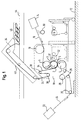
- Fig. 1 also shows a bonding device 32, whereby glue is applied to the outer radial side of the wavy band 20, especially on the crowns radially indicating outside.
- the corrugated strip 20 carrying the adhesive and the smooth strip 24 enter in the support slot 5 together, to be pressed against one another, this support representing a first step of bonding.
- the compound band 34, formed by the band corrugated 20 and the smooth strip 24 then runs through deviations 36, 38 in a transport device 40 which places the composite strip (cardboard corrugated single side) in loops on a longitudinal transport device 44, as illustrated in 46.
- the profile vertices PS1 and PS2 and the profile valleys PT1 and PT2 extend essentially parallel to the axes of the rollers, but they can also be tilted relative to the latter.
- Fig. 2 the engagement conditions between the first grooved roller 1 and the second grooved roller 2 are shown in detail in linearized or unrolled representation.
- the grooved roller 1 has PS1 profile vertices and PT1 profile valleys as well as PF1 flanks linking these.
- Grooved roller 2 has profile tops PS2 and PT2 profile valleys as well as PF2 profile flanks linking these last.
- the construction is arranged so that the PS1 profile vertices have a circular cylindrical curvature with a radius of curvature RS1, the vertices of profile PS2 have a cylindrical curvature circular with a radius of curvature RS2, the valleys of profile PT1 have a circular cylindrical curvature with a radius of curvature RT1, the valleys of profile PT2 have a circular cylindrical curvature with a radius of RT2 curvature and that the side flanks PF1 and PF2 are each formed by tangents to neighboring circular cylindrical curvatures.
- the line in dashes is obtained by approximating the profile of the first grooved roller 1 to the profile of the second grooved roller 2.
- the distance between PF2 and PF1 ' corresponds approximately to the thickness of the paper of the corrugated strip 20, which is obtained by compression of the continuous strip 16 into a corrugated strip 20 in the apex areas of the corrugated slot 3, as shown in Fig. 1.
- roller diameters grooved 1 and 2 can be identical or different.
- Fig. 3 we recognize a PS2 profile top of the grooved roller 2 in meshing with a cylindrical circumferential face U4 of the roller support 4 in linearized or unrolled representation.
- the smooth strip 24 is pressed against the corrugated strip 20 between the top of the PS2 profile of the grooved roller 2 and the circumferential face of the support roller 4, namely against a layer of glue 48 having been applied to the tops corrugation 50 of the corrugated strip 20 by the bonding device 32 according to Fig. 1.
- the relatively strong curved peaks 52 are supported by a flat side of another flat strip not shown here, if a corrugated board double sided is formed later.
- Machine operation is quieter due to pressure reduced surface area and weaker knocks resulting between the rollers 2 and 4.
- the take-in factor remains practically equal to that of a corresponding symmetrical profile (the tuck-in factor is defined as the ratio of paper length tucked in with that of the corrugated paper, i.e. the length of the strip continues to that of the corrugated board obtained).
- the flank angles ⁇ and ⁇ according to Fig. 2 can be maintained approximately equal to the angles of the sides with symmetrical profiles conventional.
- the profile peaks PS1, PS2 and the valleys of profile PT1, PT2 cooperate for the wavy deformation, or in other words: that the deformation of the profile is obtained by subjecting the continuous strip 16 to the influence of the pressure between a top of profile PS2 of the second grooved roller 2 or lower grooved roller 2 and a profile valley PT1 of the first grooved roller 1 or upper grooved roller 1, or by subject to the influence of the pressure between the profile vertices PS1 of the first grooved roller 1 or upper grooved roller 1 and the valleys of PT2 profile of the second grooved roller or lower grooved roller, respectively, as is evident from FIG. 2.
- angle ⁇ also decreases.
- a decrease in angle ⁇ means an additional change in the factor of re-entry in the sense of a reduction in paper consumption.
Abstract
Description
L'invention concerne un appareil pour la fabrication de carton ondulé, comportant un premier rouleau cannelé et un deuxième rouleau cannelé formant ensemble une fente à ondulation, un rouleau d'appui formant une fente d'appui avec le deuxième rouleau cannelé, des moyens d'admission pour admettre une bande continue à la fente à ondulation, dans laquelle la bande continue est deformée en bande ondulée, des moyens d'admission pour admettre une bande lisse à la fente d'appui, dans laquelle la bande lisse est appuyée à la bande ondulée par l'entremise de moyens adhésifs, et des moyens de transport pour transporter la bande composée formée par le rapprochement de la bande ondulée et la bande lisse, chacun des deux rouleaux cannelés ayant sur sa face extérieure un profit cannelé avec des sommets de profit et des vallées de profit s'étendant dans la direction de l'axe respective coopérant pour la déformation ondulée, des sommets de profit et des vallées de profit succédants de chaque rouleau cannelé étant liés par des flancs de profit et les sommets de profit de chaque rouleau cannelé ayant en outre une courbure plus forte que celle des vallées de profit de l'autre rouleau cannelé coopérant avec eux pour la déformation ondulée.The invention relates to an apparatus for manufacturing corrugated cardboard, comprising a first grooved roller and a second grooved roller together forming a corrugated slot, a support roller forming a support slot with the second grooved roller, inlet means to admit a continuous strip to the corrugated slot, in which the continuous strip is deformed into corrugated strip, inlet means to admit a smooth strip at the support slot, in which the strip smooth is supported on the corrugated strip by means of adhesive means, and transport means for transporting the composite tape formed by the approximation of the corrugated strip and the smooth strip, each of the two fluted rollers having a fluted profit on its outer face with profit peaks and profit valleys extending in the direction of the respective axis cooperating for the wavy deformation, vertices of profit and succeeding profit valleys of each fluted roll being linked by profit flanks and profit peaks of each roll fluted, moreover having a greater curvature than that of the valleys of profit from the other grooved roller cooperating with them for the deformation wavy.
Des appareils de ce genre sont réalisés avec des rouleaux cannelés de formes différentes, le profit étant déterminé par l'écart et la hauteur des dents. Lors de la fabrication, la bande de papier est comprimée sous pression et influence de chaleur entre les profits des rouleaux cannelés coopérants et ensuite collés avec une bande couvrante lisse. D'habitude, ceci s'effectue également sous influence de chaleur et pression par l'entremise d'un routeau d'appui ou rouleau de compression. Devices of this kind are made with fluted rollers of different forms, the profit being determined by the difference and the height of the teeth. During production, the paper strip is compressed under pressure and influence of heat between profits of fluted rollers cooperants and then glued with a smooth covering strip. Usually, this is also done under the influence of heat and pressure by through a support routine or compression roller.
Le processus de gaufrage lui-même s'effectue entre les sommets cannelés ou sommets de profit d'un rouleau cannelé et les surfaces de base cannelées ou vallées de profit respectives de l'autre rouleau cannelé. D'habitude, les flancs ne participent pas au processus de gaufrage. Dans des constructions de ce genre la différence entre les rayons des sommets de profit et des vallées de profit coopérants jouent un rôle important.The embossing process itself takes place between the fluted tops or profit vertices of a grooved roller and the base surfaces grooves or respective profit valleys of the other grooved roller. Usually, the flanks do not participate in the embossing process. In constructions like this the difference between the radii of the vertices profit and cooperating profit valleys play an important role.
Avec des rouleaux cannelés conventionnels, les profits des deux rouleaux cannelés sont identiques, de sorte que l'ondulation du papier dans les deux directions de pliage est identique et qu'il en résulte un profil symétrique du carton ondulé final.With conventional fluted rollers, the profits of the two rollers fluted are identical, so that the corrugation of the paper in both folding directions is identical and this results in a symmetrical profile of the final corrugated cardboard.
Le contact entre les sommets de profil du deuxième routeau cannelé et la surface essentiellement cylindrique du rouleau d'appui a lieu dans la fente d'appui, c'est-à-dire dans la zone de contact entre le deuxième rouleau cannelé et le rouleau d'appui. Il en résulte, que la distance entre les axes des deux rouleaux definie par le contact du rouleau cannelé et du rouleau d'appui varie constamment lors de la rotation des rouleaux entre une valeur maximale, quand un sommet de profil est situé près d'un plan de liaison contenant les axes des rouleaux, et une valeur minimale, quand une vallée de profil du deuxième rouleau cannelé est située dans le plan de liaison contenant les axes des rouleaux. Ces distances variantes provoquent une excitation permanente de vibrations, les amplitudes apparaissantes de vibration provoquant du marquage de surface sur le coté du rouleau d'appui de la bande lisse et pouvant causer des dommages aux fibres de papier dans la fente d'appui, surtout dans le domaine des résonances. Plus l'écart du profit cannelé est grand, plus les amplitudes de vibration endommageantes peuvent augmenter. Pour résoudre ce problème, on pourrait envisager des opérations avec des valeurs de pression réduites et une période d'influence élevée entre le deuxième rouleau cannelé et le rouleau d'appui et prévoir par compensation une période plus longue d'influence pour obténir une liaison intense entre la bande ondulée et la bande lisse.The contact between the profile vertices of the second fluted rout and the essentially cylindrical surface of the backing roller takes place in the slot support, i.e. in the contact area between the second roller grooved and the support roller. As a result, the distance between the axes of the two rollers defined by the contact of the grooved roller and the roller support constantly varies during the rotation of the rollers between a value maximum, when a profile vertex is located near a connecting plane containing the axes of the rollers, and a minimum value, when a valley in profile of the second grooved roller is located in the connection plane containing the axes of the rollers. These varying distances cause a permanent excitation of vibrations, the amplitudes appearing vibration causing surface marking on the side of the backing roller of the smooth strip which can cause damage to the paper fibers in the support slot, especially in the area of resonances. The bigger the gap the greater the grooved profit, the greater the amplitudes of vibration damage can increase. To solve this problem, we could consider operations with reduced pressure values and a period of high influence between the second grooved roller and the support roller and allow a longer period by compensation influence to obtain an intense bond between the corrugated strip and the smooth strip.
Il faut prendre en considération que la courbure et notamment la courbure d'apex des sommets de profil du deuxième rouleau cannelé est un facteur essentiel qui influence les dommages du papier sur le coté du rouleau d'appui de la bande lisse. Plus le rayon de courbure des sommets de profil est grand, plus la pression de Hertz agissant sur le papier diminue.It must be taken into account that the curvature and in particular the curvature apex of the profile tops of the second grooved roller is a factor essential that influences paper damage on the side of the roll support of the smooth strip. The greater the radius of curvature of the profile vertices the larger, the lower the Hertz pressure acting on the paper.
D'autre côté, on ne peut pas réduire ta courbure à volonté ou autrement dit, on ne peut pas augmenter le rayon de courbure dans la zone d'apex des sommets de profil du deuxiéme rouleau cannelé à volonté. C'est que, l'écart étant donné, l'angle du flanc par rapport à un cercle partiel circulaire du profil monte avec le rayon de courbure. Ceci mène facilement à ce qu'un roulement des profils du premier et du deuxième rouleau cannelé est gêné: le papier est surchargé et finalement les dents s'accrochent les uns dans les autres. L'augmentation de l'angle de flanc peut être compensé par une augmentation de l'écart, mais cette mesure n'est pas efficace, si un écart defini est souhaité en vue de la rigidité de pression de la bande composée formée par la bande lisse et la bande ondulée.On the other hand, we cannot reduce your curvature at will or in other words, you cannot increase the radius of curvature in the apex area of the profile tops of the second grooved roller at will. The difference is given, the angle of the flank with respect to a partial circular circle of the profile rises with the radius of curvature. This easily leads to a rolling of the profiles of the first and second fluted roller is hampered: the paper is overloaded and eventually the teeth get caught in the other. The increase in the sidewall angle can be compensated by a increase in the gap, but this measure is not effective if a gap defined is desired in view of the pressure stiffness of the compound tape formed by the smooth strip and the wavy strip.
En outre l'augmentation de l'écart provoque lui-même un risque augmenté de l'excitation de vibrations, parce que l'écart est également responsable pour les variations de la distance entre les axes du deuxième rouleau canneté et du rouleau d'appui, à cause d'une simple raison géometrique: un écart augmenté provoque des variations augmentées de la distance radiale entre les axes du deuxième rouleau cannelé et du rouleau d'appui.In addition, the increase in the spread creates an increased risk of vibration excitation, because the deviation is also responsible for variations in the distance between the axes of the second roller quirkiness and the support roller, for a simple geometric reason: a increased deviation causes increased variations in radial distance between the axes of the second grooved roller and the support roller.
L'idée de réduire des dommages sur le côté du rouleau d'appui de la bande lisse par l'augmentation du rayon des sommets provoque en outre également l'effet désavantageux d'une augmentation de la consommation du papier, parce que le cours du papier entre un apex de sommet de profil et un apex de vallée de profil des rouleaux cannelés s'éloigne de plus en plus de la ligne droite de liaison entre les deux points d'apex représentant la ligne la plus courte de liaison entre ces points d'apex.The idea of reducing damage to the side of the tape support roller smooth by increasing the radius of the vertices further causes also the disadvantageous effect of an increase in consumption of paper, because the course of the paper enters a profile apex and a profile valley apex of the fluted rollers moves further and further over the straight connecting line between the two apex points representing the shortest line of connection between these apex points.
L'invention a pour but d'agencer un appareil du genre tel que mentionné au préambule de façon que l'excitation de vibrations soit réduite et que le risque de marquage sur la bande composée correspondante ainsi que du dommage des fibres soit réduit. En outre le risque d'un engrènement mutuel, c'est-à-dire le risque d'un accrochement des dents coopérants des deux rouleaux cannelés est à éviter.The invention aims to arrange an apparatus of the kind as mentioned in preamble so that the vibration excitation is reduced and the risk of marking on the corresponding composite tape as well as fiber damage is reduced. In addition the risk of meshing mutual, that is to say the risk of a catching of the cooperating teeth of the two fluted rollers should be avoided.
Pour atteindre ce but, il est proposé selon l'invention, que les sommets de profil du premier rouleau cannelé ont une courbure plus forte que celle des sommets de profil du deuxième rouleau cannelé et que, si souhaité, les vallées de profil du premier rouleau cannelé ont une courbure moins forte que celle des vallées de profil du deuxième rouleau cannelé.To achieve this goal, it is proposed according to the invention, that the vertices of profile of the first fluted roller have a greater curvature than that of profile tops of the second grooved roller and, if desired, the profile valleys of the first fluted roller have less curvature than that of the profile valleys of the second grooved roller.
La bande composée fabriquée dans un appareil selon l'invention peut être un carton ondulé simple face à user tel qu'il est, par exemple pour envelopper des articles cylindriques. La bande composée peut aussi être un produit préparatoire pour un carton ondulé deux faces ou à plusieurs couches. L'expression "carton ondulé" comporte notamment des bandes composées, qui sont fabriquées en usant des bandes simples contenant des fibres et surtout des fibres de cellulose. Cependant, il n'est pas exclus, que la bande composée consiste d'autres matériaux, par exemple des bandes de matière synthétique, qui peuvent en principe être usiné pour la fabrication de bandes composées ondulées simple face.The composite strip produced in an apparatus according to the invention can be a single-sided corrugated board to use as it is, for example for wrap cylindrical items. The compound tape can also be a preparatory product for two or more sides corrugated board layers. The term "corrugated cardboard" includes especially bands compounds, which are produced using single strips containing fibers and especially cellulose fibers. However, it is not excluded that the composite strip consists of other materials, for example strips of synthetic material, which can in principle be machined for the manufacture of single-sided corrugated compound strips.
L'invention est basée sur l'idée, qu'une excitation de vibrations augmentée et des charges augmentés apparaissent essentiellement uniquement là, où les nervures de profil du deuxième rouleau cannelé sont en contact sous pression avec le rouleau d'appui, la bande ondulée et la bande lisse étant intercalées.The invention is based on the idea, that an increased vibration excitation and increased charges appear mainly only where the profile ribs of the second grooved roller are in contact under pressure with the backing roller, the corrugated strip and the smooth strip being interspersed.
Auprès des sommets de profil plus fortement courbés du premier rouleau cannelé avec l'agencement selon l'invention, des cimes plus fortement courbées de la bande ondulée sont formées. Ces cimes plus fortement courbées de la bande ondulée ne présentent aucun désavantage pour le produit respectif. Même si la bande composée correspondante est ultérieurement usinée en carton ondulé double face (Doubleface), les cimes plus fortement courbées de la bande ondulée sont collées à une bande lisse de papier dans une ligne de jonction essentiellement plane, où aucune vibration ne peut apparaítre et où ainsi l'influence du rayon de sommet est limitée.Near the more strongly curved profile tops of the first roller grooved with the arrangement according to the invention, crowns more strongly curved of the corrugated strip are formed. These peaks more strongly curved of the corrugated strip have no disadvantage for the respective product. Even if the corresponding compound tape is subsequently machined from double-sided corrugated cardboard (Doubleface), the tops more strongly curved of the corrugated strip are glued to a smooth strip of paper in an essentially flat junction line, where none vibration cannot appear and where thus the influence of the vertex radius is limited.
La proposition de l'invention peut être appliquée indifféremment de la question, si les sommets de profil des rouleaux cannelés sont courbés en arc de cercle ou présentent une autre forme de courbure, par exemple une forme de courbure formée par une combinaison de plusieurs arcs de cercle. En cas d'une courbure des sommets de profil des rouleaux cannelés en arc de cercle l'idée de l'invention se présente de façon que les sommets de profil du premier rouleau cannelé ont un rayon de courbure plus petit que celui des sommets de profil du deuxième rouleau cannelé. Les vallées de profil des deux rouleaux cannelés peuvent également être courbées en arc de cercle, notamment quand les sommets de profil sont également courbés en arc de cercle; dans ce cas, les vallées de profil du premier rouleau cannelé ont un rayon de courbure plus grand que celui des vallées de profil du deuxième rouleau cannelé.The proposal of the invention can be applied indifferently from the question, if the profile vertices of the fluted rollers are bent in arc of a circle or have another form of curvature, for example a form of curvature formed by a combination of several arcs of a circle. In the case of a curvature of the profile vertices of the arc fluted rollers of circle the idea of the invention is presented so that the vertices of profile of the first grooved roller have a radius of curvature smaller than that of the profile tops of the second grooved roller. The valleys of profile of the two fluted rollers can also be curved in an arc in a circle, especially when the profile vertices are also curved in an arc; in this case, the profile valleys of the first roller fluted have a greater radius of curvature than that of the profile valleys of the second grooved roller.
De préférence, les deux rouleaux cannelés sont agencés avec un écart identique, c'est-à-dire ils ont la même distance entre des apex succédants des sommets de profil et des apex succédants des vallées de profil Preferably, the two fluted rollers are arranged with a gap identical, i.e. they have the same distance between successive apices profile vertices and succeeding apexes of profile valleys
Une forme préférée est obtenue, quand la différence entre le rayon de courbure des vallées de profil du deuxième rouleau cannelé et le rayon de courbure des sommets de profil du premier rouleau cannelé est environ ou de préférence exactement égale à la différence entre le rayon de courbure des vallées de profil du premier rouleau cannelé et le rayon de courbure des sommets de profil du deuxième rouleau cannelé.A preferred shape is obtained, when the difference between the radius of curvature of the profile valleys of the second grooved roller and the radius of curvature of the profile vertices of the first fluted roller is approximately or preferably exactly equal to the difference between the radius of curvature profile valleys of the first fluted roller and the radius of curvature of the profile tops of the second grooved roller.
Le cours des flancs entre des sommets de profil et de vallées de profil succédants est variable dans une large gamme, tant qu' on assure, qu'il n' y a pas de coincement. L'idée de l'invention peut par exemple également être combinée avec le principe des dits "profils d'os", auprès desquels les sommets de profil sont epaissis dans leur étendue le long du cercle partiel par un agencement concave des flancs. Un tel "profil d'os" est par exemple montré et decrit dans l'imprimé "Die Einseitige Gruppe" (le groupe simple face), numéro de publication 1 (793D)0,5 de l'entreprise Peters Maschinenfabrik GmbH, Rondenbarg 9-17, 22525 Hamburg. Quant au "profil d'os", référence est également faite au brevet EP 0 098 936.The course of the flanks between peaks in profile and valleys in profile successors is variable in a wide range, as long as it is ensured, that it does there is no jamming. The idea of the invention can for example also be combined with the principle of so-called "bone profiles", with which the profile vertices are thickened in their extent along the partial circle by a concave arrangement of the sides. Such a "bone profile" is for example shown and described in the print "Die Einseitige Gruppe" (the simple group face), Peters company publication number 1 (793D) 0.5 Maschinenfabrik GmbH, Rondenbarg 9-17, 22525 Hamburg. As to "bone profile", reference is also made to patent EP 0 098 936.
Selon un autre aspect, l'invention concerne un procédé pour la fabrication de carton ondulé, une bande continue étant passée à travers une première fente de rouleau (fente à ondulation) entre deux rouleaux cannelés coopérants, à savoir un premier rouleau cannelé et un deuxième rouleau cannelé, et étant deformée en bande ondulée avec des premières et des deuxièmes cimes d'ondulation succédantes indiquant des directions opposées, en formant, lors de ce passage, une première cime d'ondulation entre chaque vallée de profil du premier rouleau cannelé et un sommet de profil respectif du deuxième rouleau cannelé, en formant ensuite une deuxième cime d'ondulation entre un sommet de profil du premier rouleau cannelé et une vallée de profil du deuxième rouleau cannelé, en formant ensuite de nouveau une première cime d'ondulation entre une vallée de profil du premier rouleau cannelé et un sommet de profit du deuxième rouleau cannelé etc., et une première bande lisse étant collée contre les premières cimes d'ondulation de la bande ondulée toujours en contact avec le deuxième rouleau cannelé dans une deuxième fente de rouleau (fente d'appui) entre le deuxième rouleau cannelé et un rouleau d'appui.According to another aspect, the invention relates to a method for manufacturing of corrugated cardboard, a continuous strip having passed through a first roller slot (corrugated slot) between two grooved rollers cooperating, namely a first grooved roller and a second roller grooved, and being deformed into a corrugated strip with firsts and second successive wavy peaks indicating directions opposite, forming, during this passage, a first crown of undulation between each profile valley of the first fluted roller and a top of respective profile of the second grooved roller, then forming a second crown of undulation between a top of the profile of the first roller grooved and a profile valley of the second grooved roller, forming then again a first peak of undulation between a valley of profile of the first grooved roll and a profit peak of the second grooved roller etc., and a first smooth strip being glued against the first undulations of the corrugated strip always in contact with the second grooved roller in a second roller slot (slot support) between the second grooved roller and a support roller.
Lors de ce procédé les premières cimes d'ondulation sont formées d'une courbure plus petite entre les vallées de profil du premier rouleau cannelé et les sommets de profil du deuxième rouleau cannelé et les deuxièmes cimes d'ondulation sont formées d'une courbure plus grande entre les sommets de profil du premier rouleau cannelé et les vallées de profil du deuxième rouleau cannelé. Ce procédé peut être exécuté avec l'appareil selon l'invention.During this process the first ripple peaks are formed of a smaller curvature between the profile valleys of the first fluted roller and the profile vertices of the second grooved roller and the second wave crowns are formed by a greater curvature between the profile vertices of the first grooved roller and profile valleys of the second grooved roller. This process can be performed with the device according to the invention.
Selon un procédé avancé, les premières et les deuxièmes cimes d'ondulation sont formées d'une courbure environ cylindrique circulaire au moins dans la zone d'apex, et cela d'un rayon de courbure plus grand dans la zone d'apex des premières cimes d'ondulation et d'un rayon de courbure plus petit dans la zone d'apex des deuxièmes cimes d'ondulation.According to an advanced process, the first and second peaks are formed with a circular cylindrical curvature at least in the apex area, and that of a larger radius of curvature in the area apex of the first wave crowns and a radius of curvature more small in the apex area of the second crowns.
Les flancs de liaison de la bande ondulée entre des premières et des deuxièmes cimes d'ondulation succédantes et des deuxièmes et des premières cimes d'ondulation succédantes peuvent être formés essentiellement en ligne droite et essentiellement sans pression.The connecting flanks of the corrugated strip between first and second second successive peaks of waves and second and first successive wavy peaks can be formed essentially in a straight line and essentially without pressure.
Pour obtenir un carton ondulé double face, une deuxième bande lisse peut être collée aux apex des deuxièmes cimes d'ondulation. Il est vrai que ces apex ont une courbure plus forte ou, autrement dit, un rayon de courbure plus petit. Cependant, l'apparition des problèmes de l'excitation de vibrations et le risque de marquage sont limités à cause de l'attachement de la deuxième bande lisse.To obtain a double-sided corrugated board, a second smooth strip can be stuck to the apices of the second wavy peaks. It is true that these apexes have a greater curvature or, in other words, a radius of curvature smaller. However, the onset of problems with arousal vibrations and the risk of scarring are limited due to attachment of the second smooth strip.
Enfin, selon un troisième aspect l'invention concerne un carton ondulé, comportant une bande ondulée avec des premières et des deuxièmes cimes d'ondulation succédantes indiquant des directions opposées relatif au plan de la bande, et une première bande lisse en contact avec les premières cimes d'ondulation et collée aux apex, les premières cimes d'ondulation ayant une courbure plus petite que celle des deuxièmes cimes d'ondulation.Finally, according to a third aspect, the invention relates to corrugated cardboard, having a wavy band with first and second tops of successive waves indicating opposite directions relative to the plane of the strip, and a first smooth strip in contact with the first crowns of ripple and stuck to the apices, the first crowns of ripple having a smaller curvature than that of the second crowns.
Ce carton ondulé peut être fabriqué selon le procédé décrit ci-dessus.This corrugated cardboard can be produced according to the process described above.
Les premières cimes d'ondulation et les deuxièmes cimes d'ondulation peuvent avoir une courbure d'arc de circle au moins dans la zone d'apex respective, le rayon de courbure des premières cimes d'ondulation étant plus grand que le rayon de courbure des deuxièmes cimes d'ondulation.The first wave summits and the second wave peaks may have a circular arc curvature at least in the apex area respective, the radius of curvature of the first crowns of ripple being greater than the radius of curvature of the second peaks.
Les flancs de liaison de la bande ondulée peuvent s'étendre essentiellement en ligne droite entre une première et une deuxième cime d'ondulation respective. Les flancs de liaison de la bande ondulée peuvent être essentiellement sans gaufrage entre une première et une deuxième cime d'ondulation respective, de façon que leur rigidité ne soit pas affectée.The connecting flanks of the corrugated strip can extend essentially in a straight line between a first and a second peak respective. The connecting flanks of the corrugated strip can be essentially without embossing between a first and a second crown respective corrugation, so that their rigidity is not affected.
Des flancs de liaison succédants de la bande ondulée peuvent former des angles essentiellement identiques avec le plan de la bande ondulée entre une première cime d'ondulation et une deuxième cime d'ondulation respective et entre une deuxième cime d'ondulation et une première cime de la bandee ondulée, respectivement.Successive connecting flanks of the corrugated strip can form essentially identical angles with the plane of the wavy strip between a first wave crown and a second wave peak respective and between a second crown of undulation and a first crown of the corrugated strip, respectively.
Une deuxième bande lisse peut être en contact avec et collée aux apex des deuxièmes cimes d'ondulation.A second smooth strip can be in contact with and glued to the apexes of the second wave crowns.
Quant à l'art antérieur, référence est faite aux documents suivants:
L'invention se distingue de toutes ces objections essentiellement en ce que selon les objections, des profils essentiellement symétriques de la bande ondulée sont fabriqués, tandis que selon l'invention, des premières cimes d'ondulation des profils finals de la bande ondulée ont une courbure plus petite et des deuxièmes cimes d'ondulation ont une courbure plus forte ou autrement dit: les cimes d'ondulation saillant du plan de la bande ondulée dans l'une direction ont une courbure différente de celle des cimes d'ondulation saillant du plan de la bande ondulée dans l'autre direction.The invention differs from all these objections essentially in that depending on the objections, essentially symmetrical profiles of the strip wavy are produced, while according to the invention, the first crowns corrugation of the final profiles of the corrugated strip have more curvature small and second wavy peaks have greater curvature or in other words: the peaks of undulation projecting from the plane of the corrugated strip in one direction have a different curvature than that of the tops corrugation projecting from the plane of the corrugated strip in the other direction.
Les figures annexées illustrent l'invention à partir d'un exemple de réalisation.
- Fig. 1
- montre une vue d'ensemble d'un appareil selon l'invention pour la fabrication de carton ondulé simple face;
- Fig. 2
- montre les conditions d'engrènement entre les deux rouleaux cannelés d'un appareil selon l'invention et
- Fig. 3
- montre les conditions d'engrènement entre les deuxièmes rouleaux cannelés et le rouleau d'appui d'un appareil selon l'invention.
- Fig. 1
- shows an overview of an apparatus according to the invention for manufacturing single-sided corrugated cardboard;
- Fig. 2
- shows the meshing conditions between the two fluted rollers of an apparatus according to the invention and
- Fig. 3
- shows the meshing conditions between the second grooved rollers and the support roller of an apparatus according to the invention.
A la Fig. 1, un bâti est designé par 10; il est posé sur une fondation de
machine 12. Le bâti loge un premier rouleau cannelé 1, un deuxième rouleau
cannelé 2 et un rouleau d'appui 4. Le premier rouleau cannelé 1 est appuyé
contre le deuxième rouleau cannelé 2 et en outre le rouleau d'appui 4 est
appuyé contre le deuxième rouleau canneté 2 par des moyens d'appui. Le
premier et le deuxième rouleau cannelé 1, 2 forment ensemble une fente à
ondulation 3; le rouleau d'appui 4 et le deuxième rouleau cannelé 2 forment
ensemble une fente d'appui 5.In Fig. 1, a frame is designated by 10; it rests on a foundation of
machine 12. The frame houses a first
A partir d'un réservoir montré à 14 au schéma-bloc, une bande continue 16
court au premier rouleau cannelé 1 par une poulie de déviation 18 et le long
du premier rouleau cannelé 1 à la fente à ondulation 3. Après son passage
à travers la fente à ondulation 3 la bande continue 16, tout d'abord lisse,
est deformée en bande ondulée 20. Supportée sur le deuxième rouleau
cannelé 2, cette bande ondulée 20 court en direction de la fente d'appui 5
qui reste à être décrite en detail. A partir d'un réservoir 22 une bande lisse
24 court par un rouleau de déviation 26 et par des moyens de serrage 28
jusqu'au rouleau d'appui 4 et supportée sur celui-ci dans la fente d'appui 5.
Dans la fente d'appui 5, la bande ondulée 20 est jointe avec la bande lisse
24.From a reservoir shown at 14 in the block diagram, a
La déformation de la bande continue 16 en bande ondulée 20 est réalisée
en humidifiant la bande continue 16 tout d'abord lisse avant son entrée
dans la fente à ondulation 3 par un dispositif d'humidification 30
schématiquement indiqué et en le chauffant, par exemple par la poulie de
déviation 18 chauffée à la vapeur. La bande continue ainsi humidifiée et
chauffée traverse ensuite la fente à ondulation 3 formée par les rouleaux
cannelés 1, 2 chauffés à environ 180°C. Après son passage à travers la
fente à ondulation 3, la bande ondulée 20 entretemps née de la bande
continue 16 est tellement stabilisée en sa forme ondulée qu'elle traverse la
distance jusqu'à la fente d'appui 5 supportée sur le rouleau cannelé 2. Le
contact entre la bande ondulée 20 et le rouleau cannelé 2 peut être amélioré
en appuyant la bande ondulée 20 contre la face extérieure du rouleau
cannelé 2 par une surpression extérieure dans une chambre de surpression
non montrée ou en provoquant une dépression à l'intérieur du rouleau
cannelé 2, laquelle est par exemple appliquée par des rainures
circonférentielles auprès les vallées de profil du rouleau cannelé 2, de façon
que la bande ondulée 20 est appuyée contre le profil circonférentiel du
rouleau cannelé 2 par cette dépression sous l'influence simultanée de la
pression atmosphérique sur le côté radial extérieur de la bande ondulée 20.The deformation of the
De manière schématique, Fig. 1 montre également un dispositif de collage
32, par lequel de la colle est appliquée sur le côté radial extérieur de la
bande ondulée 20, surtout sur les cimes d'ondulation radialement indiquant
l'extérieur. La bande ondulée 20 portant la colle et la bande lisse 24 entrent
dans la fente d'appui 5 ensemble, pour y être appuyées l'une contre l'autre,
cet appui représantant une première étappe de collage. En maintenant une
tension environ constante la bande composée 34, formée par la bande
ondulée 20 et la bande lisse 24, court ensuite par des déviations 36, 38
dans un dispositif de transport 40 lequel pose la bande composée (carton
ondulé simple face) en boucles sur un dispositif de transport longitudinal 44,
comme illustré à 46.Schematically, Fig. 1 also shows a
Dans cet exemple, les sommets de profil PS1 et PS2 et les vallées de profil PT1 et PT2 s'étendent essentiellement parallel aux axes des rouleaux, mais ils peuvent aussi être inclinés par rapport à ces derniers.In this example, the profile vertices PS1 and PS2 and the profile valleys PT1 and PT2 extend essentially parallel to the axes of the rollers, but they can also be tilted relative to the latter.
A la Fig. 2, les conditions d'engrènement entre le premier rouleau cannelé
1 et le deuxième rouleau cannelé 2 sont montrées en detail en
représentation linéarisée ou déroulée. Le rouleau cannelé 1 comporte des
sommets de profil PS1 et des vallées de profil PT1 ainsi que des flancs PF1
liant ces derniers. Le rouleau cannelé 2 comporte des sommets de profil
PS2 et des vallées de profil PT2 ainsi que des flancs de profil PF2 liant ces
derniers. Dans l'exemple, la construction est agencée de façon que les
sommets de profil PS1 ont une courbure cylindrique circulaire avec un rayon
de courbure RS1, les sommets de profil PS2 ont une courbure cylindrique
circulaire avec un rayon de courbure RS2, les vallées de profil PT1 ont une
courbure cylindrique circulaire avec un rayon de courbure RT1, les vallées
de profil PT2 ont une courbure cylindrique circulaire avec un rayon de
courbure RT2 et que les flancs de profil PF1 et PF2 sont formés chacun par
des tangentes aux courbures cylindriques circulaires voisinées. La ligne en
tirets est obtenue par le rapprochement du profil du premier rouleau cannelé
1 au profil du deuxième rouleau cannelé 2. La distance entre PF2 et PF1'
correspond environ à l'épaisseur du papier de la bande ondulée 20, laquelle
est obténue par la compression de la bande continue 16 en bande ondulée
20 dans les zones des sommets de la fente à ondulation 3, comme indiqué
à la Fig. 1.In Fig. 2, the engagement conditions between the first
On reconnaít sans plus que les inéquations suivantes sont satisfaites:
Dans l'exemple, les valeurs suivantes sont valables pour les rayons de
courbure:
On prenne en considération les differences entre les rayons
On prenne aussi en considération que l'écart t des profils du rouleau cannelé
1 et du rouleau cannelé 2 est identique. Les diamètres des rouleaux
cannelés 1 et 2 peuvent être identiques ou différents. We also take into account that the difference t of the profiles of the
Enfin on prenne en considération que la distance d entre le flanc PF2 et le
flanc PF1' déplacé en position d'opération a une valeur maximale à l'hauteur
moyenne des flancs, ce qui empêche un coincement entre les flancs lors de
la rotation des rouleaux cannelés 1, 2.Finally we take into consideration that the distance d between the flank PF2 and the
flank PF1 'moved to operating position has a maximum value at height
flanks average, which prevents jamming between the flanks when
the rotation of the
A la Fig. 3, on reconnaít un sommet de profil PS2 du rouleau cannelé 2 en
engrènement avec une face circonférentielle cylindrique U4 du rouleau
d'appui 4 en représentation linéarisée ou déroulée. La bande lisse 24 est
appuyée contre la bande ondulée 20 entre le sommet de profil PS2 du
rouleau cannelé 2 et la face circonférentielle du rouleau d'appui 4, à savoir
contre une couche de colle 48 ayant été appliquée sur les cimes
d'ondulation 50 de la bande ondulée 20 par le dispositif de collage 32 selon
la Fig. 1.In Fig. 3, we recognize a PS2 profile top of the
Les rayons de courbure relativement grands RS2 du sommet de profil PS2
et RT1 de la vallée de profil PT1 résultent en un rayon de courbure
relativement grand (courbure petite) des cimes d'ondulation 50 là, où elles
sont collées à la bande lisse 24 dans la fente d'appui 5, comme on
reconnaít à la Fig. 3. Il en résulte une pression superficielle de Hertz limitée
à ces positions-là.Relatively large radii of curvature RS2 from the top of the PS2 profile
and RT1 of the profile valley PT1 result in a radius of curvature
relatively large (small curvature) of the wave crowns 50 where they
are glued to the
Les cimes d'ondulation 52 courbées relativement fort, prennent appui à une
face plane d'une autre bande plane non montrée ici, si un carton ondulée
double face est formée plus tard.The relatively strong
L'opération de la machine est plus tranquille à cause de la pression
superficielle réduite et les coups plus faibles résultant entre les rouleaux 2
et 4.Machine operation is quieter due to pressure
reduced surface area and weaker knocks resulting between the
Lors d'un collage éventuel des cimes d'ondulation 52 pour un agencement
double face, la consommation de colle est faible; grâce à la surface collée
réduite, des "effets de washboard" restent limités. Le facteur de rentrage
reste pratiquement égal à celui d'un profil symétrique correspondant (le
facteur de rentrage est defini comme le rapport de la longueur du papier
rentré à celle du papier ondulé, c'est-à-dire de la longueur de la bande
continue à celle du carton ondulé obtenu). Malgré les rayons de courbures
grands RT1 et RS2 les angles de flanc α et β selon Fig. 2 peuvent être
maintenus environ égal aux angles des flancs auprès des profils symétriques
conventionnels.During a possible gluing of the
Il est encore évoqué que les sommets de profil PS1, PS2 et les vallées de
profil PT1, PT2 coopèrent pour la déformation ondulée, ou autrement dit:
que la déformation du profil est obtenue en soumettant la bande continue
16 à l'influence de la pression entre un sommet de profil PS2 du deuxième
rouleau cannelé 2 ou rouleau cannelé 2 inférieur et une vallée de profil PT1
du premier rouleau cannelé 1 ou rouleau cannelé 1 supérieur, ou en la
soumettant à l'influence de la pression entre les sommets de profil PS1 du
premier rouleau cannelé 1 ou rouleau cannelé 1 supérieur et les vallées de
profil PT2 du deuxième rouleau cannelé ou rouleau cannelé inférieur,
respectivement, comme est évident de la Fig. 2.It is also mentioned that the profile peaks PS1, PS2 and the valleys of
profile PT1, PT2 cooperate for the wavy deformation, or in other words:
that the deformation of the profile is obtained by subjecting the
On peut également voir l'invention sous un autre aspect de la façon
suivante: On part de nouveau d'un agencement des rouleaux cannelés avec
des profils identiques des deux rouleaux cannelés et on suppose, que le
rayon de courbure RS2 (étant egal au rayon de courbure RS1 dans le cas
des profils identiques des rouleaux cannelés) est suffisamment grand pour
limiter des excitations des vibrations et des marquages sur la bande
composée à des valeurs admissibles. Maintenant on réduit le rayon de
courbure RS1 du rouleau cannelé 1 supérieur sans changer le rayon de
courbure RS2 du rouleau cannelé inférieur. Dans ce cas-là, l'angle β ne varie
pas, mais l'angle α diminue. Ainsi la "capacité de marche" des profils est
améliorée, c'est-à-dire le risque d'un rapprochement trop fort des profils et
d'un coincement trop fort de la bande continue 16 est réduit. Another aspect of the invention can also be seen in the way
next: We start again from an arrangement of fluted rollers with
identical profiles of the two fluted rollers and it is assumed that the
radius of curvature RS2 (being equal to radius of curvature RS1 in the case
identical profiles of the grooved rollers) is large enough to
limit excitations of vibrations and markings on the strip
composed to admissible values. Now we reduce the radius of
curvature RS1 of the upper
Simultanément, le facteur de rentrage et ainsi la consommation de papier sont réduits.Simultaneously, the take-up factor and thus the paper consumption are reduced.
En outre, suite à la réduction du rayon de courbure RS1, on peut réduire le rayon de courbure RT2. Par conséquent, l'angle β diminue également. Une diminution de l'angle β signifie un changement additionnel du facteur de rentrage au sens d'une réduction de la consommation de papier.In addition, following the reduction of the radius of curvature RS1, the radius of curvature RT2. Consequently, the angle β also decreases. A decrease in angle β means an additional change in the factor of re-entry in the sense of a reduction in paper consumption.
Claims (17)
caractérisé en ce que
les sommets de profil (PS1) du premier rouleau cannelé (1) ont une courbure plus forte que celle des sommets de profil (PS2) du deuxième rouleau cannelé (2).Apparatus for manufacturing corrugated cardboard, comprising a first fluted roll (1) and a second fluted roll (2) together forming a corrugated slot (3), a support roller (4) forming a support slot (5 ) with the second grooved roller (2), inlet means (18) for admitting a continuous strip (16) to the corrugated slot (3), in which the continuous strip (16) is deformed into a corrugated strip (20 ), inlet means (26,28) for admitting a smooth strip (24) to the support slot (5), in which the smooth strip (24) is pressed against the corrugated strip (20) by the through adhesive means, and transport means (36,38,40) for transporting the composite strip (34) formed by bringing the corrugated strip (20) and the smooth strip (24) together, each of the two fluted rollers ( 1,2) having on its outer face a grooved profile with profile vertices (PS1, PS2) and profile valleys (PT1, PT2) cooperating for the wavy deformation e, profile vertices (PS1, PS2) and profile valleys (PT1, PT2) succeeding each grooved roller (1,2) being linked by profile flanks (PF1, PF2) and the profile vertices (PS1 , PS2) of each fluted roller (1,2) further having a greater curvature than that of the profile valleys (PT2, PT1) of the other fluted roller cooperating with them for the wavy deformation,
characterized in that
the profile vertices (PS1) of the first grooved roller (1) have a greater curvature than that of the profile vertices (PS2) of the second grooved roller (2).
caractérisé en ce que
les vallées de profil (PT1) du premier rouleau cannelé (1) ont une courbure moins forte que celle des vallées de profil (PT2) du deuxième rouleau cannelé (2).Apparatus according to claim 1,
characterized in that
the profile valleys (PT1) of the first fluted roller (1) have a lesser curvature than that of the profile valleys (PT2) of the second fluted roller (2).
caractérisé en ce que
les sommets de profil (PS1,PS2) des deux rouleaux cannelés (1,2) sont courbés en arc de cercle et que les sommets de profil (PS1) du premier rouleau cannelé (1) ont un rayon de courbure (RS1) plus petit que celui des sommets de profil (PS2) du deuxième rouleau cannelé (2).Apparatus according to claim 1 or 2,
characterized in that
the profile vertices (PS1, PS2) of the two fluted rollers (1,2) are curved in a circular arc and that the profile vertices (PS1) of the first fluted roller (1) have a smaller radius of curvature (RS1) than that of the profile tops (PS2) of the second grooved roller (2).
caractérisé en ce que
les vallées de profil (PT1,PT2) des deux rouleaux cannelés (1,2) sont courbées en arc de cercle et que les vallées de profil (PT1) du premier rouleau cannelé (1) ont un rayon de courbure (RT1) plus grand que celui des vallées de profil (PT2) du deuxième rouleau cannelé (2).Apparatus according to any one of claims 1 to 3,
characterized in that
the profile valleys (PT1, PT2) of the two fluted rollers (1,2) are curved in a circular arc and that the profile valleys (PT1) of the first fluted roller (1) have a greater radius of curvature (RT1) than that of the profile valleys (PT2) of the second grooved roller (2).
caractérisé en ce que
les deux rouleaux cannelés (1,2) ont un écart identique, c'est-à-dire la même distance entre des apex succédants des sommets de profil et des apex succédants des vallées de profil.Apparatus according to any one of claims 1 to 4,
characterized in that
the two grooved rollers (1,2) have an identical gap, that is to say the same distance between successive apices of the profile vertices and successive apices of the profile valleys.
caractérisé en ce que
la différence entre le rayon de courbure (RT2) des vallées de profil (PT2) du deuxième rouleau cannelé (2) et le rayon de courbure (RS1) des sommets de profil (PS1) du premier rouleau cannelé (1) est environ ou de préférence exactement égale à la différence entre le rayon de courbure (RT1) des vallées de profil (PT1) du premier rouleau cannelé (1) et le rayon de courbure (RS2) des sommets de profil (PS2) du deuxième rouleau cannelé (2).Apparatus according to any one of claims 4 and 5,
characterized in that
the difference between the radius of curvature (RT2) of the profile valleys (PT2) of the second fluted roller (2) and the radius of curvature (RS1) of the profile vertices (PS1) of the first fluted roller (1) is approximately or preference exactly equal to the difference between the radius of curvature (RT1) of the profile valleys (PT1) of the first fluted roller (1) and the radius of curvature (RS2) of the profile vertices (PS2) of the second fluted roller (2) .
une bande continue (16) étant passée à travers une première fente de rouleau (3) entre deux rouleaux cannelés (1,2) coopérants, à savoir un premier rouleau cannelé (1) et un deuxième rouleau cannelé (2), et étant deformée en bande ondulée (20) avec des premières et des deuxièmes cimes d'ondulation succédantes (50 resp. 52) indiquant des directions opposées, en formant, lors de ce passage, une première cime d'ondulation (50) entre chaque vallée de profil (PT1) du premier rouleau cannelé (1) et un sommet de profil (PS2) respectif du deuxième rouleau cannelé (2), en formant ensuite une deuxième cime d'ondulation (52) entre un sommet de profil (PS1) du premier rouleau cannelé (1) et une vallée de profil (PT2) du deuxième rouleau cannelé (2), en formant ensuite de nouveau une première cime d'ondulation (50) entre une vallée de profil (PT1) du premier rouleau cannelé (1) et un sommet de profil (PS2) du deuxième rouleau cannelé (2) etc., et une première bande lisse (24) étant collée contre les premières cimes d'ondulation (50) de la bande ondulée (20) toujours en contact avec le deuxième rouleau cannelé (2) dans une deuxième fente de rouleau (5) entre le deuxième rouleau cannelé (2) et un rouleau d'appui (4),
caractérisé en ce que
les premières cimes d'ondulation (50) sont formées d'une courbure plus petite entre les vallées de profil (PT1) du premier rouleau cannelé (1) et les sommets de profil (PS2) du deuxième rouleau cannelé (2) et les deuxièmes cimes d'ondulation (52) sont formées d'une courbure plus grande entre les sommets de profil (PS1) du premier rouleau cannelé (1) et les vallées de profil (PT2) du deuxième rouleau cannelé (2). Process for the production of corrugated cardboard, in particular using an apparatus according to any one of Claims 1 to 6,
a continuous strip (16) being passed through a first roller slot (3) between two cooperating grooved rollers (1,2), namely a first grooved roller (1) and a second grooved roller (2), and being deformed in a wavy band (20) with first and second successive peaks of wave (50 resp. 52) indicating opposite directions, forming, during this passage, a first peak of wave (50) between each profile valley (PT1) of the first fluted roller (1) and a respective profile top (PS2) of the second fluted roller (2), then forming a second crown (52) between a profile top (PS1) of the first roller grooved (1) and a profile valley (PT2) of the second grooved roller (2), then again forming a first corrugation crown (50) between a profile valley (PT1) of the first grooved roller (1) and a profile top (PS2) of the second grooved roller (2) etc., and a first strip smooth (24) being glued against the first corrugation peaks (50) of the corrugated strip (20) still in contact with the second grooved roller (2) in a second roller slot (5) between the second grooved roller (2 ) and a support roller (4),
characterized in that
the first corrugation peaks (50) are formed by a smaller curvature between the profile valleys (PT1) of the first fluted roller (1) and the profile vertices (PS2) of the second fluted roller (2) and the second wave crowns (52) are formed by a greater curvature between the profile vertices (PS1) of the first fluted roller (1) and the profile valleys (PT2) of the second fluted roller (2).
caractérisé en ce que
les premières (50) et les deuxièmes (52) cimes d'ondulation (50,52) sont respectivement formées d'une courbure environ cylindrique circulaire au moins dans la zone d'apex, et cela d'un rayon de courbure (RT1) plus grand dans la zone d'apex des premières cimes d'ondulation (50) et d'un rayon de courbure (RT2) plus petit dans la zone d'apex des deuxièmes cimes d'ondulation (52).Method according to claim 7,
characterized in that
the first (50) and the second (52) crowns of ripple (50,52) are respectively formed of an approximately cylindrical circular curvature at least in the apex zone, and that of a radius of curvature (RT1) larger in the apex area of the first ripple peaks (50) and a smaller radius of curvature (RT2) in the apex area of the second ripple peaks (52).
caractérisé en ce que
les flancs de liaison de la bande ondulée (20) entre des premières et des deuxièmes cimes d'ondulation (50 resp. 52) succédantes et des deuxièmes et des premières cimes d'ondulation (52 resp.50) succédantes sont formés essentiellement en ligne droite et essentiellement sans pression.Method according to claim 7 or 8,
characterized in that
the connecting flanks of the corrugated strip (20) between first and second successive crowns (50 resp. 52) and second and first successive crowns (52 resp.50) are formed essentially in line straight and essentially without pressure.
caractérisé en ce que
une deuxième bande lisse est collée aux apex des deuxièmes cimes d'ondulation (52).Process according to any one of Claims 7 to 9,
characterized in that
a second smooth strip is glued to the apexes of the second crowns (52).
caractérisé en ce que
les premières cimes d'ondulation (50) ont une courbure plus petite que celle des deuxièmes cimes d'ondulation (52). Corrugated cardboard, comprising a corrugated strip (20) with successive first and second corrugation tops (50 resp. 52) indicating opposite directions relative to the plane of the strip, and a first smooth strip (24) in contact with the first crowns of ripple (50) and glued to the apices, in particular manufactured according to the method according to any one of Claims 7 to 10,
characterized in that
the first wave crowns (50) have a smaller curvature than that of the second wave crowns (52).
caractérisé en ce que
les premières cimes d'ondulation (50) et les deuxièmes cimes d'ondulation (52) ont une courbure d'arc de circle au moins dans la zone d'apex respective, le rayon de courbure (RS2) des premières cimes d'ondulation (50) étant plus grand que le rayon de courbure (RS1) des deuxièmes cimes d'ondulation (52).Corrugated cardboard according to claim 11,
characterized in that
the first crowns of ripple (50) and the second crowns of ripple (52) have a curvature of an arc of a circle at least in the respective apex zone, the radius of curvature (RS2) of the first crowns of ripple (50) being greater than the radius of curvature (RS1) of the second crowns of ripple (52).
caractérisé en ce que
les premières et les deuxièmes cimes d'ondulation (50 resp. 52) sont deformées de façon ondulée entre un sommet de profil (PS2 resp. PS1) et une vallée de profil (PT1 resp. PT2) respective des rouleaux cannelés coopérants.Corrugated cardboard according to claim 11 or 12,
characterized in that
the first and second crowns of undulation (50 resp. 52) are deformed in an undulating fashion between a top of profile (PS2 resp. PS1) and a valley of profile (PT1 resp. PT2) respective of the co-operating grooved rollers.
caractérisé en ce que
les flancs de liaison de la bande ondulée (20) s'étendent essentiellement en ligne droite entre une première et une deuxième cime d'ondulation respective (50 resp. 52).Corrugated cardboard according to any one of Claims 11 to 13,
characterized in that
the connecting flanks of the corrugated strip (20) extend essentially in a straight line between a first and a second respective wave crown (50 resp. 52).
caractérisé en ce que
les flancs de liaison de la bande ondulée (20) sont essentiellement sans gaufrage entre une première (50) et une deuxième (52) cime d'ondulation respective.Corrugated cardboard according to any one of Claims 11 to 14,
characterized in that
the connecting flanks of the corrugated strip (20) are essentially without embossing between a first (50) and a second (52) respective wave crown.
caractérisé en ce que
des flancs de liaison succédants de la bande ondulée (20) forment des angles essentiellement identiques avec le plan de la bande ondulée entre une première cime d'ondulation (50) et une deuxième cime d'ondulation (52) respective et entre une deuxième cime d'ondulation (52) et une première cime de la bandee ondulée (50), respectivement.Corrugated cardboard according to any one of claims 11 to 15,
characterized in that
successive connecting flanks of the corrugated strip (20) form essentially identical angles with the plane of the corrugated strip between a first corrugation crown (50) and a respective second corrugation crown (52) and between a second crown corrugation (52) and a first peak of the corrugated strip (50), respectively.
caractérisé en ce que
une deuxième bande lisse est en contact avec et collée aux apex des deuxièmes cimes d'ondulation (52).Corrugated cardboard according to any one of claims 11 to 16,
characterized in that
a second smooth strip is in contact with and glued to the apices of the second wavy peaks (52).
Applications Claiming Priority (2)
| Application Number | Priority Date | Filing Date | Title |
|---|---|---|---|
| DE19740512A DE19740512A1 (en) | 1997-09-15 | 1997-09-15 | Device for the production of corrugated cardboard |
| DE19740512 | 1997-09-15 |
Publications (2)
| Publication Number | Publication Date |
|---|---|
| EP0901898A1 true EP0901898A1 (en) | 1999-03-17 |
| EP0901898B1 EP0901898B1 (en) | 2004-12-08 |
Family
ID=7842395
Family Applications (1)
| Application Number | Title | Priority Date | Filing Date |
|---|---|---|---|
| EP98117240A Expired - Lifetime EP0901898B1 (en) | 1997-09-15 | 1998-09-11 | Device as well as process for the manufacture of corrugated paper |
Country Status (3)
| Country | Link |
|---|---|
| US (1) | US6112793A (en) |
| EP (1) | EP0901898B1 (en) |
| DE (2) | DE19740512A1 (en) |
Families Citing this family (4)
| Publication number | Priority date | Publication date | Assignee | Title |
|---|---|---|---|---|
| CN1302918C (en) * | 2003-01-31 | 2007-03-07 | 王子制纸株式会社 | Surface corrugated paper sticking machine and dual-side corrugated thin sheet |
| DE102007012160A1 (en) | 2007-03-12 | 2008-09-18 | Stipo Jelica | Corrugated card board producing device, has pressure and corrugated rollers, where device produces card board that is used in making folded box whose side panel edges are not placed parallel to corrugation process of cardboard |
| CN102229262A (en) * | 2011-07-13 | 2011-11-02 | 上海大松瓦楞辊有限公司 | N-corrugated-type corrugated roll |
| JP2016504973A (en) * | 2012-06-15 | 2016-02-18 | コルセル・アイピー・リミテッド | Improvements in and related to paperboard manufacturing |
Citations (6)
| Publication number | Priority date | Publication date | Assignee | Title |
|---|---|---|---|---|
| US3053309A (en) * | 1958-07-21 | 1962-09-11 | S & S Corrugated Paper Mach | Corrugating flute contour |
| DE2611325A1 (en) * | 1976-03-17 | 1977-09-29 | Bhs Bayerische Berg | SINGLE-SIDED CORRUGATED CARDBOARD MACHINE |
| EP0098936A1 (en) * | 1982-06-16 | 1984-01-25 | Werner H. K. Peters Maschinenfabrik GmbH | A single facer corrugating machine |
| US4531996A (en) * | 1984-05-09 | 1985-07-30 | Corrugating Roll Corporation | Single facer corrugating machine |
| GB2284433A (en) * | 1993-11-20 | 1995-06-07 | Langston Corp | Manufacture of corrugated board |
| EP0681909A2 (en) * | 1994-05-13 | 1995-11-15 | Mitsubishi Jukogyo Kabushiki Kaisha | Single facer and corrugating roll for the same |
Family Cites Families (4)
| Publication number | Priority date | Publication date | Assignee | Title |
|---|---|---|---|---|
| US1971667A (en) * | 1931-03-26 | 1934-08-28 | Seamless Rubber Company Inc | Method of and apparatus for treating sheet rubber |
| US2717423A (en) * | 1952-01-04 | 1955-09-13 | Us Rubber Co | Method of making embossed battery separators |
| US2838416A (en) * | 1953-09-21 | 1958-06-10 | Bancroft & Sons Co J | Production of inlay embossed fabrics |
| US5316828A (en) * | 1991-04-25 | 1994-05-31 | Miller Ray R | Reinforced fluted medium and corrugated fiberboard made using the medium |
-
1997
- 1997-09-15 DE DE19740512A patent/DE19740512A1/en not_active Withdrawn
-
1998
- 1998-09-11 DE DE69828005T patent/DE69828005T2/en not_active Expired - Fee Related
- 1998-09-11 US US09/151,470 patent/US6112793A/en not_active Expired - Fee Related
- 1998-09-11 EP EP98117240A patent/EP0901898B1/en not_active Expired - Lifetime
Patent Citations (6)
| Publication number | Priority date | Publication date | Assignee | Title |
|---|---|---|---|---|
| US3053309A (en) * | 1958-07-21 | 1962-09-11 | S & S Corrugated Paper Mach | Corrugating flute contour |
| DE2611325A1 (en) * | 1976-03-17 | 1977-09-29 | Bhs Bayerische Berg | SINGLE-SIDED CORRUGATED CARDBOARD MACHINE |
| EP0098936A1 (en) * | 1982-06-16 | 1984-01-25 | Werner H. K. Peters Maschinenfabrik GmbH | A single facer corrugating machine |
| US4531996A (en) * | 1984-05-09 | 1985-07-30 | Corrugating Roll Corporation | Single facer corrugating machine |
| GB2284433A (en) * | 1993-11-20 | 1995-06-07 | Langston Corp | Manufacture of corrugated board |
| EP0681909A2 (en) * | 1994-05-13 | 1995-11-15 | Mitsubishi Jukogyo Kabushiki Kaisha | Single facer and corrugating roll for the same |
Also Published As
| Publication number | Publication date |
|---|---|
| US6112793A (en) | 2000-09-05 |
| EP0901898B1 (en) | 2004-12-08 |
| DE69828005T2 (en) | 2005-04-14 |
| DE69828005D1 (en) | 2005-01-13 |
| DE19740512A1 (en) | 1999-04-29 |
Similar Documents
| Publication | Publication Date | Title |
|---|---|---|
| EP0793751B1 (en) | Absorbent multilayer sheet and method for making same | |
| FR2685436A1 (en) | SUMMER FOR A WORKING ELEMENT, SUCH AS A SQUEEGEE BLADE, FOR MANUFACTURING BANDS OF FIBROUS MATERIAL. | |
| FR2809661A1 (en) | Forming noise-damping material for e.g. head arms of computer disc drives, involves subjecting laminate to compressive forces to reduce initial thickness of metal layers and viscoelastic layer of laminate | |
| FR2653793A1 (en) | ||
| EP0662045B1 (en) | Machine and method for making a sheet of single face corrugated cardboard | |
| US6800052B1 (en) | Corrugating machine and corrugating roll design for the same | |
| EP0901898B1 (en) | Device as well as process for the manufacture of corrugated paper | |
| EP1330352B1 (en) | Method for making a multiply absorbent paper sheet | |
| CA2233889A1 (en) | Improved single facer with small intermediate corrugating roll | |
| EP0758295B1 (en) | Machine and method of manufacture of single-face corrugated board by traction glueing | |
| FR2643397A1 (en) | PAPER MACHINE WITH TWO FILTERS | |
| FR2746703A1 (en) | METHOD AND MACHINE FOR MANUFACTURING PANELS | |
| FR2682133A1 (en) | LAMELLAR BRISTOL LIGHT. | |
| EP0794050B1 (en) | Corrugated packaging material and machine and process for the manufacture of corrugated packaging material | |
| EP0921938B1 (en) | Machine and method for making a sheet of single-face corrugated paperboard using traction feed prior to rolls | |
| FR2575700A1 (en) | Process for manufacturing a wooden tube from an element of small thickness and element employed | |
| FR2763018A1 (en) | RIGID CORRUGATED BOARD | |
| FR2641492A1 (en) | Method of continuously manufacturing tubular corrugated board (cardboard) | |
| EP1990177A2 (en) | Apparatus for applying a cover sheet on panels | |
| EP1033241A1 (en) | Rigid corrugated cardboard | |
| JPH04137833U (en) | single facer | |
| FR2688738A1 (en) | Method for manufacturing one or more profiled sections made from flexible material, particularly from paper, cardboard, composite materials or the like, and device for implementing this method | |
| FR2668099A1 (en) | Shell with parallel semi-cylindrical cells (cavities), method and machine for manufacturing it | |
| EP0055160A1 (en) | Machine for shaping flexible materials, with or without predetermined alternations of flutes and flat spaces, and product so obtained | |
| JP2003300266A (en) | Corrugating medium for corrugated cardboard material, corrugated cardboard sheet, manufacturing method for corrugating medium for corrugated cardboard material, and manufacturing method for corrugated cardboard sheet |
Legal Events
| Date | Code | Title | Description |
|---|---|---|---|
| PUAI | Public reference made under article 153(3) epc to a published international application that has entered the european phase |
Free format text: ORIGINAL CODE: 0009012 |
|
| 17P | Request for examination filed |
Effective date: 19980911 |
|
| AK | Designated contracting states |
Kind code of ref document: A1 Designated state(s): DE FR GB IT |
|
| AX | Request for extension of the european patent |
Free format text: AL;LT;LV;MK;RO;SI |
|
| AKX | Designation fees paid |
Free format text: DE FR GB IT |
|
| 17Q | First examination report despatched |
Effective date: 20030131 |
|
| RAP1 | Party data changed (applicant data changed or rights of an application transferred) |
Owner name: BHS CORRUGATED MASCHINEN-UND ANLAGENBAU GMBH |
|
| RTI1 | Title (correction) |
Free format text: DEVICE AS WELL AS PROCESS FOR THE MANUFACTURE OF CORRUGATED PAPER |
|
| GRAP | Despatch of communication of intention to grant a patent |
Free format text: ORIGINAL CODE: EPIDOSNIGR1 |
|
| GRAS | Grant fee paid |
Free format text: ORIGINAL CODE: EPIDOSNIGR3 |
|
| GRAA | (expected) grant |
Free format text: ORIGINAL CODE: 0009210 |
|
| AK | Designated contracting states |
Kind code of ref document: B1 Designated state(s): DE FR GB IT |
|
| REG | Reference to a national code |
Ref country code: GB Ref legal event code: FG4D Free format text: NOT ENGLISH |
|
| GBT | Gb: translation of ep patent filed (gb section 77(6)(a)/1977) |
Effective date: 20041208 |
|
| REF | Corresponds to: |
Ref document number: 69828005 Country of ref document: DE Date of ref document: 20050113 Kind code of ref document: P |
|
| PGFP | Annual fee paid to national office [announced via postgrant information from national office to epo] |
Ref country code: FR Payment date: 20050920 Year of fee payment: 8 |
|
| PGFP | Annual fee paid to national office [announced via postgrant information from national office to epo] |
Ref country code: GB Payment date: 20050929 Year of fee payment: 8 |
|
| PLBE | No opposition filed within time limit |
Free format text: ORIGINAL CODE: 0009261 |
|
| STAA | Information on the status of an ep patent application or granted ep patent |
Free format text: STATUS: NO OPPOSITION FILED WITHIN TIME LIMIT |
|
| 26N | No opposition filed |
Effective date: 20050909 |
|
| PG25 | Lapsed in a contracting state [announced via postgrant information from national office to epo] |
Ref country code: DE Free format text: LAPSE BECAUSE OF NON-PAYMENT OF DUE FEES Effective date: 20060401 |
|
| PGFP | Annual fee paid to national office [announced via postgrant information from national office to epo] |
Ref country code: IT Payment date: 20060930 Year of fee payment: 9 |
|
| GBPC | Gb: european patent ceased through non-payment of renewal fee |
Effective date: 20060911 |
|
| REG | Reference to a national code |
Ref country code: FR Ref legal event code: ST Effective date: 20070531 |
|
| PG25 | Lapsed in a contracting state [announced via postgrant information from national office to epo] |
Ref country code: GB Free format text: LAPSE BECAUSE OF NON-PAYMENT OF DUE FEES Effective date: 20060911 |
|
| PG25 | Lapsed in a contracting state [announced via postgrant information from national office to epo] |
Ref country code: FR Free format text: LAPSE BECAUSE OF NON-PAYMENT OF DUE FEES Effective date: 20061002 |
|
| PG25 | Lapsed in a contracting state [announced via postgrant information from national office to epo] |
Ref country code: IT Free format text: LAPSE BECAUSE OF NON-PAYMENT OF DUE FEES Effective date: 20070911 |