EP0901722B1 - Subscriber unit for cdma wireless communication system - Google Patents
Subscriber unit for cdma wireless communication system Download PDFInfo
- Publication number
- EP0901722B1 EP0901722B1 EP97926888A EP97926888A EP0901722B1 EP 0901722 B1 EP0901722 B1 EP 0901722B1 EP 97926888 A EP97926888 A EP 97926888A EP 97926888 A EP97926888 A EP 97926888A EP 0901722 B1 EP0901722 B1 EP 0901722B1
- Authority
- EP
- European Patent Office
- Prior art keywords
- data
- channel
- channel data
- phase
- rate
- Prior art date
- Legal status (The legal status is an assumption and is not a legal conclusion. Google has not performed a legal analysis and makes no representation as to the accuracy of the status listed.)
- Expired - Lifetime
Links
Images


Classifications
-
- H—ELECTRICITY
- H04—ELECTRIC COMMUNICATION TECHNIQUE
- H04L—TRANSMISSION OF DIGITAL INFORMATION, e.g. TELEGRAPHIC COMMUNICATION
- H04L1/00—Arrangements for detecting or preventing errors in the information received
- H04L1/004—Arrangements for detecting or preventing errors in the information received by using forward error control
- H04L1/0056—Systems characterized by the type of code used
- H04L1/0059—Convolutional codes
-
- H—ELECTRICITY
- H04—ELECTRIC COMMUNICATION TECHNIQUE
- H04B—TRANSMISSION
- H04B7/00—Radio transmission systems, i.e. using radiation field
- H04B7/24—Radio transmission systems, i.e. using radiation field for communication between two or more posts
- H04B7/26—Radio transmission systems, i.e. using radiation field for communication between two or more posts at least one of which is mobile
- H04B7/2628—Radio transmission systems, i.e. using radiation field for communication between two or more posts at least one of which is mobile using code-division multiple access [CDMA] or spread spectrum multiple access [SSMA]
- H04B7/264—Radio transmission systems, i.e. using radiation field for communication between two or more posts at least one of which is mobile using code-division multiple access [CDMA] or spread spectrum multiple access [SSMA] for data rate control
-
- H—ELECTRICITY
- H04—ELECTRIC COMMUNICATION TECHNIQUE
- H04J—MULTIPLEX COMMUNICATION
- H04J13/00—Code division multiplex systems
- H04J13/16—Code allocation
- H04J13/18—Allocation of orthogonal codes
-
- H—ELECTRICITY
- H04—ELECTRIC COMMUNICATION TECHNIQUE
- H04L—TRANSMISSION OF DIGITAL INFORMATION, e.g. TELEGRAPHIC COMMUNICATION
- H04L1/00—Arrangements for detecting or preventing errors in the information received
- H04L1/004—Arrangements for detecting or preventing errors in the information received by using forward error control
- H04L1/0045—Arrangements at the receiver end
-
- H—ELECTRICITY
- H04—ELECTRIC COMMUNICATION TECHNIQUE
- H04L—TRANSMISSION OF DIGITAL INFORMATION, e.g. TELEGRAPHIC COMMUNICATION
- H04L1/00—Arrangements for detecting or preventing errors in the information received
- H04L1/004—Arrangements for detecting or preventing errors in the information received by using forward error control
- H04L1/0056—Systems characterized by the type of code used
- H04L1/0071—Use of interleaving
-
- H—ELECTRICITY
- H04—ELECTRIC COMMUNICATION TECHNIQUE
- H04L—TRANSMISSION OF DIGITAL INFORMATION, e.g. TELEGRAPHIC COMMUNICATION
- H04L1/00—Arrangements for detecting or preventing errors in the information received
- H04L1/08—Arrangements for detecting or preventing errors in the information received by repeating transmission, e.g. Verdan system
-
- H—ELECTRICITY
- H04—ELECTRIC COMMUNICATION TECHNIQUE
- H04B—TRANSMISSION
- H04B1/00—Details of transmission systems, not covered by a single one of groups H04B3/00 - H04B13/00; Details of transmission systems not characterised by the medium used for transmission
- H04B1/69—Spread spectrum techniques
- H04B1/707—Spread spectrum techniques using direct sequence modulation
-
- H—ELECTRICITY
- H04—ELECTRIC COMMUNICATION TECHNIQUE
- H04B—TRANSMISSION
- H04B2201/00—Indexing scheme relating to details of transmission systems not covered by a single group of H04B3/00 - H04B13/00
- H04B2201/69—Orthogonal indexing scheme relating to spread spectrum techniques in general
- H04B2201/707—Orthogonal indexing scheme relating to spread spectrum techniques in general relating to direct sequence modulation
- H04B2201/70701—Orthogonal indexing scheme relating to spread spectrum techniques in general relating to direct sequence modulation featuring pilot assisted reception
-
- H—ELECTRICITY
- H04—ELECTRIC COMMUNICATION TECHNIQUE
- H04J—MULTIPLEX COMMUNICATION
- H04J13/00—Code division multiplex systems
- H04J13/0007—Code type
- H04J13/0022—PN, e.g. Kronecker
-
- H—ELECTRICITY
- H04—ELECTRIC COMMUNICATION TECHNIQUE
- H04J—MULTIPLEX COMMUNICATION
- H04J13/00—Code division multiplex systems
- H04J13/0007—Code type
- H04J13/004—Orthogonal
- H04J13/0048—Walsh
Definitions
- the present invention relates to communications. More particularly, the present invention relates to a novel and improved method and apparatus for high data rate CDMA wireless communication.
- Wireless communication systems including cellular, satellite and point to point communication systems use a wireless link comprised of a modulated radio frequency (RF) signal to transmit data between two systems.
- RF radio frequency
- the use of a wireless link is desirable for a variety of reasons including increased mobility and reduced infrastructure requirements when compared to wire line communication systems.
- One drawback of using a wireless link is the limited amount of communication capacity that results from the limited amount of available RF bandwidth. This limited communication capacity is in contrast to wire based communication systems where additional capacity can be added by installing additional wire line connections.
- IS-95 over the air interface standard and its derivatives such as IS-95-A (referred to hereafter collectively as the IS-95 standard) promulgated by the telecommunication industry association (TIA) and used primarily within cellular telecommunications systems.
- TIA telecommunication industry association
- CDMA code division multiple access
- Fig. 1 provides a highly simplified illustration of a cellular telephone system configured in accordance with the use of the IS-95 standard.
- a set of subscriber units 10a - d conduct wireless communication by establishing one or more RF interfaces with one or more base stations 12a - d using CDMA modulated RF signals.
- Each RF interface between a base station 12 and a subscriber unit 10 is comprised of a forward link signal transmitted from the base station 12, and a reverse link signal transmitted from the subscriber unit.
- a communication with another user is generally conducted by way of mobile telephone switching office (MTSO) 14 and public switch telephone network (PSTN) 16 .
- MTSO mobile telephone switching office
- PSTN public switch telephone network
- the links between base stations 12 , MTSO 14 and PSTN 16 are usually formed via wire line connections, although the use of additional RF or microwave links is also known.
- each subscriber unit 10 transmits user data via a single channel, non-coherent, reverse link signal at a maximum data rate of 9.6 or 14.4 kbits/sec depending on which rate set from a set of rate sets is selected.
- a non-coherent link is one in which phase information is not utilized by the received system.
- a coherent link is one in which the receiver exploits knowledge of the carrier signals phase during processing. The phase information typically takes the form of a pilot signal, but can also be estimated from the data transmitted.
- the IS-95 standard calls for a set of sixty four Walsh codes, each comprised of sixty four chips, to be used for the forward link.
- a non-coherent reverse link was selected because, in a system in which up to 80 subscriber units 10 may communicate with a base station 12 for each 1.2288 MHz of bandwidth allocated, providing the necessary pilot data in the transmission from each subscriber unit 10 would substantially increase the degree to which a set of subscriber units 10 interfere with one another.
- the ratio of the transmit power of any pilot data to the user data would be significant, and therefore also increase inter-subscriber unit interference.
- the use of a single channel reverse link signal was chosen because engaging in only one type of communication at a time is consistent with the use of wireline telephones, the paradigm on which current wireless cellular communications is based. Also, the complexity of processing a single channel is less than that associated with processing multiple channels.
- the present invention is related to providing a higher data rate, bandwidth efficient, CDMA interface over which multiple types of communication can be performed.
- WO 95/03652 describes a method and system for allocating a set of orthogonal PN code sequences of variable length among user channels operative at different data rates in a spread spectrum communication system. PN code sequences are constructed that provide orthogonality between users so that mutual interference will be reduced, thereby allowing higher capacity and better link performance.
- a set of individually gain adjusted subscriber channels are formed via the use of a set of orthogonal subchannel codes having a small number of PN spreading chips per orthogonal waveform period.
- Data to be transmitted via one of the transmit channels is low code rate error correction encoded and sequence repeated before being modulated with one of the subchannel codes, gain adjusted, and summed with data modulated using the other subchannel codes.
- the resulting summed data is modulated using a user long code and a pseudorandom spreading code (PN code) and upconverted for transmission.
- PN code pseudorandom spreading code
- the use of the short orthogonal codes provides interference suppression while still allowing extensive error correction coding and repetition for time diversity to overcome the Raleigh fading commonly experienced in terrestrial wireless systems.
- the set of sub-channel codes are comprised of four Walsh codes, each orthogonal to the remaining set and four chips in duration.
- the use of four sub-channels is preferred as it allows shorter orthogonal codes to be used, however, the use of a greater number of channels and therefore longer codes is consistent with the invention.
- pilot data is transmitted via a first one of the transmit channels and power control data transmitted via a second transmit channel.
- the remaining two transmit channels are used for transmitting non-specified digital data including user data or signaling data, or both.
- one of the two non-specified transmit channels is configured for BPSK modulation and the other for QPSK modulation. This is done to illustrate the versatility of the system. Alternatively, both channels could be BPSK modulated or QPSK modulated.
- the non-specified data is encoded where that encoding includes cyclic redundancy check (CRC) generation, convolutional encoding, interleaving, selective sequence repeating and BPSK or QPSK mapping.
- CRC cyclic redundancy check
- a novel and improved method and apparatus for high rate CDMA wireless communication is described in the context of the reverse link transmission portion of a cellular telecommunications system. While embodiments of the invention are particularly adapted for use within the multipoint-to-point reverse link transmission of a cellular telephone system, they are equally applicable to forward link transmissions. In addition, many other wireless communication systems will benefit by incorporation of embodiments of the invention, including satellite based wireless communication systems, point to point wireless communication systems and systems transmitting radio frequency signals via the use of co-axial or other broadband cables.
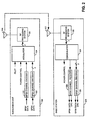
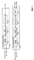
- Fig. 2 is a block diagram of receive and transmit systems configured as a subscriber unit 100 and a base station 120 in accordance with one embodiment of the invention.
- a first set of data (BPSK data) is received by BPSK channel encoder 103 , which generates a code symbol stream configured for performing BPSK modulation that is received by modulator 104.
- a second set of data (QPSK data) is received by QPSK channel encoder 102, which generates a code symbol stream configured for performing QPSK modulation that is also received by modulator 104 .
- Modulator 104 also receives power control data and pilot data, which are modulated along with the BPSK and QPSK encoded data in accordance with code division multiple access (CDMA) techniques to generate a set of modulation symbols received by RF processing system 106 .
- RF processing system 106 filters and upconverts the set of modulation symbols to a carrier frequency for transmission to the base station 120 using antenna 108. While only one subscriber unit 100 is shown, multiple subscriber units communicate with base station 120 in preferred embodiments.
- RF processing system 122 receives the transmitted RF signals by way of antenna 121 and performs bandpass filtering, downconversion to baseband, and digitization.
- Demodulator 124 receives the digitized signals and performs demodulation in accordance with CDMA techniques to produce power control, BPSK, and QPSK soft decision data.
- BPSK channel decoder 128 decodes the BPSK soft decision data received from demodulator 124 to yield a best estimate of the BPSK data
- QPSK channel decoder 126 decodes the QPSK soft decision data received by demodulator 124 to produce a best estimate of the QPSK data.
- the best estimate of first and second set of data is then available for further processing or forwarding to a next destination, and the received power control data used either directly, or after decoding, to adjust the transmit power of the forward link channel used to transmit data to subscriber unit 100 .
- Fig. 3 is a block diagram of BPSK channel encoder 103 and QPSK channel encoder 102 when configured in accordance with the exemplary embodiment of the invention.
- the BPSK data is received by CRC check sum generator 130 which generates a check sum for each 20 ms frame of the first set of data.
- the frame of data along with the CRC check sum is received by tail bit generator 132 which appends tail bits comprised of eight logic zeros at the end of each frame to provide a known state at the end of the decoding process.
- convolutional encoder 134 which performs, constraint length (K) 9, rate (R) 1/4 convolutional encoding thereby generating code symbols at a rate four times the encoder input rate (E R ).
- K constraint length
- R rate 1/4 convolutional encoding
- Block interleaver 136 performs bit interleaving on the code symbols to provide time diversity for more reliable transmission in fast fading environments.
- variable starting point repeater 138 which repeats the interleaved symbol sequence a sufficient number of times N R to provide a constant rate symbol stream, which corresponds to outputting frames having a constant number of symbols. Repeating the symbol sequence also increases the time diversity of the data to overcome fading.
- the constant number of symbols is equal to 6,144 symbols for each frame making the symbol rate 307.2 kilosymbols per second (ksps).
- repeater 138 uses a different starting point to begin the repetition for each symbol sequence. When the value of N R necessary to generate 6,144 symbols per frame is not an integer, the final repetition is only performed for a portion of the symbol sequence.
- BPSK mapper 139 which generates a BPSK code symbol stream (BPSK) of +1 and -1 values for performing BPSK modulation.
- repeater 138 is placed before block interleaver 136 so that block interleaver 136 receives the same number of symbols for each frame.
- the QPSK data is received by CRC check sum generator 140 which generates a check sum for each 20 ms frame.
- the frame including the CRC check sum is received by code tail bits generator 142 which appends a set of eight tail bits of logic zeros at the end of the frame.
- Block interleaver 146 performs bit interleaving on the symbols and the resulting interleaved symbols are received by variable starting point repeater 148 .
- Variable starting point repeater 148 repeats the interleaved symbol sequence a sufficient number of times N R using a different starting point within the symbol sequence for each repetition to generate 12,288 symbols for each frame making the code symbol rate 614.4 kilosymbols per second (ksps).
- N R is not an integer
- the final repetition is performed for only a portion of the symbol sequence.
- the resulting repeated symbols are received by QPSK mapper 149 which generates a QPSK code symbol stream configured for performing QPSK modulation comprised of an in-phase QPSK code symbol strezm of +1 and -1 values (QPSK I ), and a quadrature-phase QPSK code symbol stream of +1 and -1 values (QPSK Q ).
- repeater 148 is placed. before block interleaver 146 so that block. interleaver 146 receives the same number of symbols for each frame.
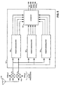
- Fig. 4 is a block diagram of modulator 104 of Fig. 2 configured in accordance with the exemplary embodiment of the invention.
- the BPSK symbols from BPSK channel encoder 103 are each modulated by Walsh code W 2 using a multiplier 150b
- the QPSK I and QPSK Q symbols from QPSK channel encoder 102 are each modulated with Walsh code W 3 using multipliers 150c and 150d .
- the power control data (PC) is modulated by Walsh code W 1 using multiplier 150a .
- Gain adjust 152 receives pilot data (PILOT), which in the preferred embodiment of the invention is comprised of the logic level associated with positive voltage, and adjusts the amplitude according to a gain adjust factor A 0 .
- PILOT pilot data
- the PILOT signal provides no user data but rather provides phase and amplitude information to the base station so that it can coherently demodulate the data carried on the remaining sub-channels, and scale the soft-decision output values for combining.
- Gain adjust 154 adjusts the amplitude of the Walsh code W 1 modulated power control data according to gain adjust factor A 1
- gain adjust 156 adjusts the amplitude of the Walsh code W 2 modulated BPSK channel data according to amplification variable A 2
- Gain adjusts 158a and b adjust the amplitude of the in-phase and quadrature-phase Walsh code W 3 modulated QPSK symbols respectively according to gain adjust factor A 3 .
- the four Walsh codes used in the preferred embodiment of the invention are shown in Table I. Walsh Code Modulation Symbols W 0 ++++ W 1 + - + - W 2 + + - - W 3 + - - +
- the W 0 code is effectively no modulation at all, which is consistent with processing of the pilot data shown.
- the power control data is modulated with the W 1 code, the BPSK data with the W 2 code, and the QPSK data with the W 3 code.
- the pilot, power control data, and BPSK data are transmitted in accordance with BPSK techniques, and the QPSK data (QPSK I and QPSK Q ) in accordance with QPSK techniques as described below. It should also be understood that it is not necessary that every orthogonal channel be used, and that the use of only three of the four Walsh codes where only one user channel is provided may be employed.
- short orthogonal codes generates fewer chips per symbol, and therefore allows for more extensive coding and repetition when compared to systems incorporating the use of longer Walsh codes. This more extensive coding and repetition provides protection against Raleigh fading which is a major source of error in terrestrial communication systems.
- the use of other numbers of codes and code lengths is consistent with embodiments of the present invention, however, the use of a larger set of longer Walsh codes reduces this enhanced protection against fading.
- the use of four chip codes is considered optimal because four channels provides substantial flexibility for the transmission of various types of data as illustrated below while also maintaining short code length.
- Summer 160 sums the resulting amplitude adjusted modulation symbols from gain adjusts 152, 154, 156 and 158a to generate summed modulation symbols 161 .
- PN spreading codes PN I and PN Q are spread via multiplication with long code 180 using multipliers 162a and b .
- the resulting pseudorandom code provided by multipliers 162a and 162b are used to modulate the summed modulation symbols 161 , and gain adjusted quadrature-phase symbols QPSK Q 163 , via complex multiplication using multipliers 164a-d and summers 166a and b .
- the resulting in-phase term X I and quadrature-phase term X Q are then filtered (filtering not shown), and upconverted to the carrier frequency within RF processing system 106 shown in a highly simplified form using multipliers 168 and an in-phase and a quadrature-phase sinusoid An offset QPSK upconversion could also be used.
- the resulting in-phase and quadrature-phase upconverted signals are summed using summer 170 and amplified by master amplifier 172 according to master gain adjust A M to generate signal s(t) which is transmitted to base station 120.
- the signal is spread and filtered to a 1.2288 MHz bandwidth to remain compatible with the bandwidth of existing CDMA channels.
- variable rate repeaters that reduce the amount of repeating N R performed in response to high input data rates
- the above described method and system of transmit signal processing allows a single subscriber unit or other transmit system to transmit data at a variety of data rates.
- an increasingly higher encoder input rate E R can be sustained.
- rate 1 ⁇ 2 convolution encoding may be performed with the rate of repetition N R increased by two.
- a set of exemplary encoder rates E R supported by various rates of repetition N R and encoding rates R equal to 1/4 and 1/2 for the BPSK channel and the QPSK channel are shown in Tables II and III respectively.
- Tables II and III show that by adjusting the number of sequence repetitions N R , a wide variety of data rates can be supported including high data rates, as the encoder input rate E R corresponds to the data transmission rate minus a constant necessary for the transmission of CRC, code tail bits and any other overhead information. As also shown by tables II and III, QPSK modulation may also be used to increase the data transmission rate.
- Rates expected to be used commonly are provided labels such as "High Rate-72" and ''High Rate-32.” Those rates noted as High Rate-72, High Rate-64, and High Rate-32 have traffic rates of 72, 64 and 32 kbps respectively, plus multiplexed in signaling and other control data with rates of 3.6, 5.2, and 5.2 kbps respectively, in the exemplary embodiment of the invention. Rates RS1-Full Rate and RS2-Full Rate correspond to rates used in IS-95 compliant communication systems, and therefore are also expected to receive substantial use for purposes of compatibility.
- the null rate is the transmission of a single bit and is used to indicate a frame erasure, which is also part of the IS-95 standard.
- the data transmission rate may also be increased by simultaneously transmitting data over two or more of the multiple orthogonal channels performed either in addition to, or instead of, increasing the transmission rate via reduction of the repetition rate N R .
- a multiplexer (not shown) could split a single data source into multiple data sources to be transmitted over multiple data sub-channels.
- the total transmit rate can be increased via either transmission over a particular channel at higher rates, or multiple transmission performed simultaneously over multiple channels, or both, until the signal processing capability of the receive system is exceeded and the error rate becomes unacceptable, or the maximum transmit power of the transmit system power is reached.
- the BPSK channel may be designated for voice information and the QPSK channel designated for transmission of digital data.
- This embodiment could be more generalized by designating one channel for transmission of time sensitive data such as voice at a lower data rate, and designating the other channel for transmission of less time sensitive data such as digital files. In this embodiment interleaving could be performed in larger blocks for the less time sensitive data to further increase time diversity.
- the BPSK channel may perform the primary transmission of data, and the QPSK channel performs overflow transmission.
- orthogonal Walsh codes eliminates or substantially reduces any interference among the set of channels transmitted from a subscriber unit, and thus minimizes the transmit energy necessary for their successful reception at the base station.
- pilot data is also transmitted via one of the orthogonal channels.
- coherent processing can be performed at the receive system by determining and removing the phase offset of the reverse link signal.
- the pilot data can be used to optimally weigh multipath signals received with different time delays before being combined in a rake receiver. Once the phase offset is removed, and the multipath signals properly weighted, the multipath signals can be combined decreasing the power at which the reverse link signal must be received for proper processing. This decrease in the required receive power allows greater transmissions rates to be processed successfully, or conversely, the interference between a set of reverse link signals to be decreased.
- gain adjusts 152 - 158 as well as master amplifier 172 further increases the degree to which the high transmission capability of the above described system can be utilized by allowing the transmit system to adapt to various radio channel conditions, transmission rates, and data types.
- the transmit power of a channel that is necessary for proper reception may change over time, and with changing conditions, in a manner that is independent of the other orthogonal channels.
- the power of the pilot channel may need to be increased to facilitate detection and synchronization at the base station. Once the reverse link signal is acquired, however, the necessary transmit power of the pilot channel would substantially decrease, and would vary depending on various factors including the subscriber units rate of movement.
- the value of the gain adjust factor A 0 would be increased during signal acquisition, and then reduced during an ongoing communication.
- the gain adjust factor A 1 may be reduced as the need to transmit power control data with a low error rate decreases. In one embodiment of the invention, whenever power control adjustment is not necessary the gain adjust factor A 1 is reduced to zero.
- the ability to gain adjust each orthogonal channel or the entire reverse link signal may be further exploited by allowing the base station 120 or other receive system to alter the gain adjust of a channel, or of the entire reverse link signal, via the use of power control commands transmitted via the forward link signal.
- the base station may transmit power control information requesting the transmit power of a particular channel or the entire reverse link signal be adjusted. This is advantageous in many instances including when two types of data having different sensitivity to error, such as digitized voice and digital data, are being transmitted via the BPSK and QPSK channels. In this case, the base station 120 would establish different target error rates for the two associated channels.
- the base station would instruct the subscriber unit to reduce the gain adjust of that channel until the actual error rate reached the target error rate. This would eventually lead to the gain adjust factor of one channel being increased relative to the other. That is, the gain adjust factor associated with the more error sensitive data would be increased relative to the gain adjust factor associated with the less sensitive data.
- the transmit power of the entire reverse link may require adjustment due to fade conditions or movement of the subscriber unit 100. In these instances, the base station 120 can do so via transmission of a single power control command.
- the total transmit power of the reverse link signal can be kept at the minimum necessary for successful transmission of each data type, whether it is pilot data, power control data, signaling data, or different types of user data. Furthermore, successful transmission can be defined differently for each data type. Transmitting with the minimum amount of power necessary allows the greatest amount of data to be transmitted to the base station given the finite transmit power capability of a subscriber unit, and also reduces the interference between subscriber units. This reduction in interference increases the total communication capacity of the entire CDMA wireless cellular system.
- the power control channel used in the reverse link signal allows the subscriber unit to transmit power control information to the base station at a variety of rates including a rate of 800 power control bits per second.
- a power control bit instructs the base station to increase or decrease the transmit power of the forward link traffic channel being used to transmit information to the subscriber unit. While it is generally useful to have rapid power control within a CDMA system, it is especially useful in the context of higher data rate communications involving data transmission, because digital data is more sensitive to errors, and the high transmission rate causes substantial amounts of data to be lost during even brief fade conditions. Given that a high speed reverse link transmission is likely to be accompanied by a high speed forward link transmission, providing for the rapid transmission of power control over the reverse link further facilitates high speed communications within CDMA wireless telecommunications systems.
- a set of encoder input rates E R defined by the particular N R are used to transmit a particular type of data. That is, data may be tranmitted at a maximum encoder input rate E R or at a set of lower encoder input rates E R, with the associated N R adjusted accordingly.
- the maximum rates correspond to the maximum rates used in IS-95 compliant wireless communication systems, referred to above with respect to Tables II and III as RS1-Full Rate and RS2-Full Rate, and each lower rate is approximately one half the next higher rate, creating a set of rates comprised of a full rate, a half rate, a quarter rate, and an eighth rate.
- the lower data rates are preferably generated by increasing the symbol repetition rate N R with value of N R for rate set one and rate set two in a BPSK channel provided in Table IV.
- Encoder Out R 1/4 (bits/frame)
- the repetition rate for a QPSK channel is twice that for the BPSK channel.
- the transmit power of the frame is adjusted according to the change in transmission rate. That is, when a lower rate frame is transmitted after a higher rate frame, the transmit power of the transmit channel over which the frame is being transmitted is reduced for the lower rate frame in proportion to the reduction in rate, and vice versa. For example, if the transmit power of a channel during the transmission of a full rate frame is transmit power T, the transmit power during the subsequent transmission of a half rate frame is transmit power T/2.
- the reduction in transmit power is preferably performed by reducing the transmit power for the entire duration of the frame, but may also be performed by reducing the transmit duty cycle such that some redundant information is "blanked out". In either case, the transmit power adjustment takes place in combination with a closed loop power control mechanism whereby the transmit power is further adjusted in response to power control data transmitted from the base station.
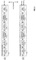
- Fig. 5 is a block diagram of RF processing system 122 and demodulator 124 of Fig. 2 configured in accordance with the exemplary embodiment of the invention.
- Multipliers 180a and 180b downconvert the signals received from antenna 121 with an in-phase sinusoid and a quadrature phase sinusoid producing in-phase receive samples R I and quadrature-phase receive samples R Q receptively.
- RF processing system 122 is shown in a highly simplified form, and that the signals are also match filtered and digitized (not shown) in accordance with widely known techniques.
- Receive samples R I and R Q are then applied to finger demodulators 182 within demodulator 124 .
- Each finger demodulator 182 processes an instance of the reverse link signal transmitted by subscriber unit 100, if such an instance is available, where each instance of the reverse link signal is generated via multipath phenomenon. While three finger demodulators are shown, the use of alternative numbers of finger processors are consistent with embodiments of the invention including the use of a single finger demodulator 182 .
- Each finger demodulator 182 produces a set of soft decision data comprised of power control data, BPSK data, and QPSK I data and QPSK Q data. Each set of soft decision data is also time adjusted within the corresponding finger demodulator 182, although time adjustment could alternatively be performed within combiner 184. Combiner 184 then sums the sets of soft decision data received from finger demodulators 182 to yield a single instance of power control, BPSK, QPSK I and QPSK Q soft decision data.
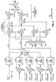
- Fig. 6 is block diagram a finger demodulator 182 of Fig. 5 configured in accordance with the exemplary embodiment of the invention.
- the R I and R Q receive samples are first time adjusted using time adjust 190 in accordance with the amount of delay introduced by the transmission path of the particular instance of the reverse link signal being processed.
- Long code 200 is mixed with pseudorandom spreading codes PN I and PN Q using multipliers 201 , and the complex conjugate of the resulting long code modulated PN I and PN Q spreading codes are complex multiplied with the time adjusted R I and R Q receive samples using multipliers 202 and summers 204 yielding terms X I and X Q .
- pilot filter 214 performs averaging over a series of summations performed by summers 208, but other filtering techniques will be apparent to one skilled in the art.
- the filtered in-phase and quadrature-phase pilot signals are used to phase rotate and scale the W 1 , and W 2 Walsh code demodulated data in accordance with BPSK modulated data via complex conjugate multiplication using multipliers 216 and adders 217 yielding soft decision power control and BPSK data.
- the W 3 Walsh code modulated data is phase rotated using the in-phase and quadrature-phase filtered pilot signals in accordance with QPSK modulated data using multipliers 218 and adders 220 , yielding soft decision QPSK data.
- the soft decision power control data is summed over 384 modulation symbols by 384 to 1 summer 222 yielding power control soft decision data.
- the phase rotated W 2 Walsh code modulated data, the W 3 Walsh code modulated data, and the power control soft decision data are then made available for combining. Alternatively, encoding and decoding is performed on the power control data as well.
- the pilot may also be used within the receive system to facilitate time tracking.
- Time tracking is performed by also processing the received data at one sample time before (early), and one sample time after (late), the present receive sample being processed.
- the amplitude of the pilot channel at the early and late sample time can be compared with the amplitude at the present sample time to determine that which is greatest. If the signal at one of the adjacent sample times is greater than that at the present sample time, the timing can be adjusted so that the best demodulation results are obtained.
- FIG. 7 is a block diagram of BPSK channel decoder 128 and QPSK channel decoder 126 ( Fig. 2 ) configured in accordance with the exemplary embodiment of the invention.
- BPSK soft decision data from combiner 184 ( Fig. 5 ) is received by accumulator 240 which stores the first sequence of 6,144/N R demodulation symbols in the received frame where N R depends on the transmission rate of the BPSK soft decision data as described above, and adds each subsequent set of 6,144/N R demodulated symbols contained in the frame with the corresponding stored accumulated symbols.
- Block deinterleaver 242 deinterleaves the accumulated soft decision data from variable starting point summer 240, and Viterbi decoder 244 decodes the deinterleaved soft decision data to produce hard decision data as well as CRC check sum results.
- QPSK decoder 126 QPSK I and QPSK Q soft decision data from combiner 184 ( Fig. 5 ) are demultiplexed into a single soft decision data stream by demux 246 and the single soft decision data stream is received by accumulator 248 which accumulates every 6,144/N R demodulation symbols where N R depends on the transmission rate of the QPSK data.
- Block deinterleaver 250 deinterleaves the soft decision data from variable starting point summer 248 , and Viterbi decoder 252 decodes the deinterleaved modulation symbols to produce hard decision data as well as CRC check sum results.
- accumulators 240 and 248 are placed after block deinterl avers 242 and 250 .
- multiple decoders are employed, each operating at a different transmission rate, and then the frame associated with the transmission rate most likely to have been used is selected based on the CRC checksum results. The use of other error checking methods is consistent with the practice of embodiments of the present invention.
Abstract
Description
Alternatively, both channels could be BPSK modulated or QPSK modulated. Before modulation, the non-specified data is encoded where that encoding includes cyclic redundancy check (CRC) generation, convolutional encoding, interleaving, selective sequence repeating and BPSK or QPSK mapping. By varying the amount of repeating performed, and not restricting the amount of repeating to an integer number of symbol sequences, a wide variety of transmission rates including high data rates can be achieved. Furthermore, higher data rates can also be achieved by transmitting data simultaneously over both non-specified transmit channels. Also, by frequently updating the gain adjust performed on each transmit channel, the total transmit power used by the transmit system may be kept to a minimum such that the interference generated between multiple transmit systems is minimised, thereby increasing the overall system capacity.
Alternatively,
| Walsh Code | Modulation Symbols |
| W0 | ++++ |
| W1 | + - + - |
| W2 | + + - - |
| W3 | + - - + |
Alternatively, rate ½ convolution encoding may be performed with the rate of repetition NR increased by two. A set of exemplary encoder rates ER supported by various rates of repetition NR and encoding rates R equal to 1/4 and 1/2 for the BPSK channel and the QPSK channel are shown in Tables II and III respectively.
| BPSK Channel | |||||
| Label | ER,BPSK (bps) | Encoder Out R=1/4 (bits/frame) | NR,R=1/4 (Repetition Rate, R=1/4) | Encoder Out R=1/2 (bits/frame) | NR,R=1/2 (Repetition Rate, R=1/2) |
| High Rate-72 | 76,800 | 6,144 | 1 | 3,072 | 2 |
| High Rate-64 | 70,400 | 5,632 | 1 1/11 | 2,816 | 2 2/11 |
| 51,200 | 4,096 | 1 1/2 | 2,048 | 3 | |
| High Rate-32 | 38,400 | 3,072 | 2 | 1,536 | 4 |
| 25,600 | 2,048 | 3 | 1,024 | 6 | |
| RS2-Full Rate | 14,400 | 1,152 | 5 1/3 | 576 | 10 2/3 |
| RS1-Full Rate | 9,600 | 768 | 8 | 384 | 16 |
| NULL | 850 | 68 | 90 6/17 | 34 | 180 12/17 |
| QPSK Channel | |||||
| Label | ER,QPSK (bps) | Encoder Out R=1/4 (bits/frame) | NR,R=1/4 (Repetition Rate, R=1/4) | Encoder Out R=1/2 (bits/frame) | NR,R=1/2 (Repetition Rate, R=1/2) |
| 153,600 | 12,288 | 1 | 6,144 | 2 | |
| High Rate-72 | 76,800 | 6,144 | 2 | 3,072 | 4 |
| High Rate-64 | 70,400 | 5,632 | 2 2/11 | 2,816 | 4 4/11 |
| 51,200 | 4,096 | 3 | 2,048 | 6 | |
| High Rate-32 | 38,400 | 3,072 | 4 | 1,536 | 8 |
| 25,600 | 2,048 | 6 | 1,024 | 12 | |
| RS2-Full Rate | 14,400 | 1,152 | 10 2/3 | 576 | 21 1/3 |
| RS1-Full Rate | 9,600 | 768 | 16 | 384 | 32 |
| NULL | 850 | 68 | 180 12/17 | 34 | 361 7/17 |
Alternatively, the BPSK channel may perform the primary transmission of data, and the QPSK channel performs overflow transmission. The use of orthogonal Walsh codes eliminates or substantially reduces any interference among the set of channels transmitted from a subscriber unit, and thus minimizes the transmit energy necessary for their successful reception at the base station.
| RS1 and RS2 Rate Sets in BPSK Channel | |||||
| Label | ER,QPSK (bps) | Encoder Out R=1/4 (bits/frame) | NR,R=1/4 (Repetition Rate, R=1/4) | Encoder Out R=1/2 (bits/frame) | NR,R=1/2 (Repetition Rate, R=1/2 |
| RS2-Full Rate | 14,400 | 1,152 | 5 1/3 | 576 | 10 2/3 |
| RS2-Half Rate | 7,200 | 576 | 10 2/3 | 288 | 21 1/3 |
| RS2-Quater Rate | 3,600 | 288 | 21 1/3 | 144 | 42 2/3 |
| RS2-Eigth Rate | 1,900 | 152 | 40 8/19 | 76 | 80 16/19 |
| RS1-Full Rate | 9,600 | 768 | 8 | 384 | 16 |
| RS1-Half Rate | 4,800 | 384 | 16 | 192 | 32 |
| RS1-Quater Rate | 2,800 | 224 | 27 3/7 | 112 | 54 6/7 |
| RS1-Eigth Rate | 1,600 | 128 | 48 | 64 | 96 |
| NULL | 850 | 68 | 90 6/17 | 34 | 180 12/17 |
Claims (12)
- A method for generating modulated data for transmission, characterised in that said data is for transmission from a first subscriber unit (100) in a set of subscriber units to a base station (120) in communication with the set of subscriber units, said method comprising:modulating (104) pilot data with a first orthogonal code (W0) to generate first channel data;modulating (104, 150a to 150d) user data with a second orthogonal code (W1, W2, W3) to produce second channel data;summing (160) said first channel data and said second channel data to generate summed data (161);modulating (164a to 164d, 166a, 166b) said summed data (161) with a long code (180) to generate the modulated data;gain adjusting (152) said first channel data by a first amount (A0); andgain adjusting (154, 156, 158a, 158b) said second channel data by a second amount (A1, A2, A3) relative to said first amount (A0).
- The method as set forth in claim 1, further comprising:modulating (150a) power control data with a third orthogonal code (W1) to produce third channel data; andsumming (160) said third channel data into said summed data (161).
- The method as set forth in claim 2, wherein:said first channel data is pilot data; andsaid second channel data is user data.
- The method as set forth in claim 2, further comprising gain adjusting (154) said third channel data.
- The method as set forth in claim 1, further comprising:modulating (150c) in-phase third data with a third orthogonal code (W3) to produce in-phase third channel data;modulating (150d) quadrature-phase third data with said third orthogonal code (W3) to produce quadrature-phase third channel data (163);summing (160) said in-phase third channel data into said summed data (161); andcomplex multiplying (164a to 164d, 166a, 166b) said summed data (161) and said quadrature-phase third channel data (163) with an in-phase spreading code and a quadrature-phase spreading code.
- A subscriber unit apparatus (100), comprising:means (104) for modulating pilot data with a first orthogonal code (W0) to generate first channel data; wherein said subscriber unit (100) further comprises:means (104, 150a to 150d) for modulating user data with a second orthogonal code (W1, W2, W3) to produce second channel data;means (160) for summing said first channel data and said second channel data to generate summed data (161);means (164a to 164d, 166a, 166b) for modulating said summed data (161) with a long code (180) to generate modulated data for transmission;means (152) for gain adjusting said first channel data by a first amount (A0); andmeans (154,156,158a, 158b) for gain adjusting said second channel data by a second amount (A1, A2, A3) relative to said first amount (A0).
- The apparatus (100) as set forth in claim 6, further comprising:means (150a) for modulating power control data with a third orthogonal code (W1) to produce third channel data; andmeans (160) for summing said third channel data into said summed data (161).
- The apparatus (100) as set forth in claim 7, wherein:said first channel data is pilot data; andsaid second channel data is user data.
- The apparatus (100) as set forth in claim 7, further comprising means (154) for gain adjusting said third channel data.
- The apparatus (100) as set forth in claim 6, further comprising:means (150c) for modulating in-phase third data with a third orthogonal code (W3) to produce in-phase third channel data;means (150d) for modulating quadrature-phase third data with said third orthogonal code (W3) to produce quadrature-phase third channel data (163);means (160) for summing said in-phase third channel data into said summed data (161); andmeans (164a to 164d, 166a, 166b) for complex multiplying said summed data (161) and said quadrature-phase third channel data (163) with an in-phase spreading code and a quadrature-phase spreading code.
- A wireless communication system, characterised by comprising:a first subscriber unit (100) according to any one of claims 6 to 10, for transmitting a first reverse link signal that includes a first set of orthogonal subchannels;a second subscriber unit (100) according to any one of claims 6 to 10, for transmitting a second reverse link signal that includes a second set of orthogonal subchannels; anda base station (120) for receiving said first reverse link signal and said second reverse link signal.
- The wireless communication system as set forth in claim 11, wherein each orthogonal channel in said first set of orthogonal channels is individually gain adjusted (152, 154, 156, 158a, 158b) and each orthogonal channel in said second set of orthogonal channels is individually gain adjusted (152, 154, 156, 158a, 158b).
Priority Applications (2)
| Application Number | Priority Date | Filing Date | Title |
|---|---|---|---|
| EP04075608A EP1453220B1 (en) | 1996-05-28 | 1997-05-28 | Subscriber unit for CDMA wireless communication system |
| EP06024896A EP1772969B1 (en) | 1996-05-28 | 1997-05-28 | Subscriber unit for CDMA wireless communication system |
Applications Claiming Priority (3)
| Application Number | Priority Date | Filing Date | Title |
|---|---|---|---|
| US654443 | 1996-05-28 | ||
| US08/654,443 US5930230A (en) | 1996-05-28 | 1996-05-28 | High data rate CDMA wireless communication system |
| PCT/US1997/009606 WO1997045970A1 (en) | 1996-05-28 | 1997-05-28 | Subscriber unit for cdma wireless communication system |
Related Child Applications (1)
| Application Number | Title | Priority Date | Filing Date |
|---|---|---|---|
| EP04075608A Division EP1453220B1 (en) | 1996-05-28 | 1997-05-28 | Subscriber unit for CDMA wireless communication system |
Publications (2)
| Publication Number | Publication Date |
|---|---|
| EP0901722A1 EP0901722A1 (en) | 1999-03-17 |
| EP0901722B1 true EP0901722B1 (en) | 2004-05-26 |
Family
ID=24624882
Family Applications (3)
| Application Number | Title | Priority Date | Filing Date |
|---|---|---|---|
| EP97926888A Expired - Lifetime EP0901722B1 (en) | 1996-05-28 | 1997-05-28 | Subscriber unit for cdma wireless communication system |
| EP04075608A Expired - Lifetime EP1453220B1 (en) | 1996-05-28 | 1997-05-28 | Subscriber unit for CDMA wireless communication system |
| EP06024896A Expired - Lifetime EP1772969B1 (en) | 1996-05-28 | 1997-05-28 | Subscriber unit for CDMA wireless communication system |
Family Applications After (2)
| Application Number | Title | Priority Date | Filing Date |
|---|---|---|---|
| EP04075608A Expired - Lifetime EP1453220B1 (en) | 1996-05-28 | 1997-05-28 | Subscriber unit for CDMA wireless communication system |
| EP06024896A Expired - Lifetime EP1772969B1 (en) | 1996-05-28 | 1997-05-28 | Subscriber unit for CDMA wireless communication system |
Country Status (17)
| Country | Link |
|---|---|
| US (4) | US5930230A (en) |
| EP (3) | EP0901722B1 (en) |
| JP (2) | JP4307553B2 (en) |
| CN (1) | CN1155168C (en) |
| AT (3) | ATE430411T1 (en) |
| AU (1) | AU736358B2 (en) |
| BR (1) | BR9709612B1 (en) |
| CA (1) | CA2256416C (en) |
| DE (3) | DE69737667T2 (en) |
| DK (1) | DK0901722T3 (en) |
| ES (3) | ES2275173T3 (en) |
| HK (2) | HK1018993A1 (en) |
| IL (2) | IL127292A (en) |
| PT (1) | PT901722E (en) |
| TW (1) | TW357503B (en) |
| WO (1) | WO1997045970A1 (en) |
| ZA (1) | ZA974388B (en) |
Families Citing this family (134)
| Publication number | Priority date | Publication date | Assignee | Title |
|---|---|---|---|---|
| ZA965340B (en) | 1995-06-30 | 1997-01-27 | Interdigital Tech Corp | Code division multiple access (cdma) communication system |
| US6678311B2 (en) | 1996-05-28 | 2004-01-13 | Qualcomm Incorporated | High data CDMA wireless communication system using variable sized channel codes |
| JPH1051354A (en) * | 1996-05-30 | 1998-02-20 | N T T Ido Tsushinmo Kk | Ds-cdma transmission method |
| JPH1098449A (en) * | 1996-09-25 | 1998-04-14 | Canon Inc | Information signal communication equipment and method therefor |
| JP3317866B2 (en) * | 1996-12-20 | 2002-08-26 | 富士通株式会社 | Spread spectrum communication system |
| JP3373746B2 (en) * | 1997-01-07 | 2003-02-04 | 株式会社鷹山 | Initial synchronization method and receiver in asynchronous cellular system between DS-CDMA base stations |
| US7787647B2 (en) | 1997-01-13 | 2010-08-31 | Micro Ear Technology, Inc. | Portable system for programming hearing aids |
| US6173007B1 (en) * | 1997-01-15 | 2001-01-09 | Qualcomm Inc. | High-data-rate supplemental channel for CDMA telecommunications system |
| US5991284A (en) | 1997-02-13 | 1999-11-23 | Qualcomm Inc. | Subchannel control loop |
| US6898197B1 (en) * | 1997-02-28 | 2005-05-24 | Interdigital Technology Corporation | Geolocation of a mobile terminal in a CDMA communication system |
| US5943331A (en) * | 1997-02-28 | 1999-08-24 | Interdigital Technology Corporation | Orthogonal code synchronization system and method for spread spectrum CDMA communications |
| JP3349918B2 (en) * | 1997-04-09 | 2002-11-25 | 沖電気工業株式会社 | Communication system, transmitting device and receiving device |
| CN1783754A (en) * | 1997-04-17 | 2006-06-07 | Ntt移动通信网株式会社 | Base station apparatus of mobile communication system |
| US6396867B1 (en) | 1997-04-25 | 2002-05-28 | Qualcomm Incorporated | Method and apparatus for forward link power control |
| CA2463381C (en) * | 1997-05-14 | 2011-11-22 | Qualcomm Incorporated | A subscriber unit and method for use in a wireless communication system |
| EP0985292B1 (en) * | 1997-05-30 | 2005-04-20 | QUALCOMM Incorporated | Method and apparatus for providing error protection for over-the-air file transfer |
| US6075792A (en) | 1997-06-16 | 2000-06-13 | Interdigital Technology Corporation | CDMA communication system which selectively allocates bandwidth upon demand |
| JP2861985B2 (en) * | 1997-06-16 | 1999-02-24 | 日本電気株式会社 | High-speed cell search method for CDMA |
| JP4874449B2 (en) | 1997-06-17 | 2012-02-15 | クゥアルコム・インコーポレイテッド | Reduced maximum and average amplitude of multichannel links |
| US6081536A (en) | 1997-06-20 | 2000-06-27 | Tantivy Communications, Inc. | Dynamic bandwidth allocation to transmit a wireless protocol across a code division multiple access (CDMA) radio link |
| US6151332A (en) | 1997-06-20 | 2000-11-21 | Tantivy Communications, Inc. | Protocol conversion and bandwidth reduction technique providing multiple nB+D ISDN basic rate interface links over a wireless code division multiple access communication system |
| US6542481B2 (en) | 1998-06-01 | 2003-04-01 | Tantivy Communications, Inc. | Dynamic bandwidth allocation for multiple access communication using session queues |
| CN1196288C (en) * | 1997-06-20 | 2005-04-06 | 三菱电机株式会社 | Method and device for variable-speed transmission |
| US6421333B1 (en) * | 1997-06-21 | 2002-07-16 | Nortel Networks Limited | Channel coding and interleaving for transmission on a multicarrier system |
| US6377809B1 (en) * | 1997-09-16 | 2002-04-23 | Qualcomm Incorporated | Channel structure for communication systems |
| US6389000B1 (en) * | 1997-09-16 | 2002-05-14 | Qualcomm Incorporated | Method and apparatus for transmitting and receiving high speed data in a CDMA communication system using multiple carriers |
| US20020051434A1 (en) * | 1997-10-23 | 2002-05-02 | Ozluturk Fatih M. | Method for using rapid acquisition spreading codes for spread-spectrum communications |
| US6101168A (en) | 1997-11-13 | 2000-08-08 | Qualcomm Inc. | Method and apparatus for time efficient retransmission using symbol accumulation |
| JP3217307B2 (en) * | 1997-11-18 | 2001-10-09 | 沖電気工業株式会社 | Wireless transmission device |
| KR100269593B1 (en) * | 1997-12-02 | 2000-10-16 | 정선종 | Orthogonal complex spreading based modulation method for multichannel transmission |
| US7936728B2 (en) | 1997-12-17 | 2011-05-03 | Tantivy Communications, Inc. | System and method for maintaining timing of synchronization messages over a reverse link of a CDMA wireless communication system |
| US9525923B2 (en) | 1997-12-17 | 2016-12-20 | Intel Corporation | Multi-detection of heartbeat to reduce error probability |
| US6222832B1 (en) | 1998-06-01 | 2001-04-24 | Tantivy Communications, Inc. | Fast Acquisition of traffic channels for a highly variable data rate reverse link of a CDMA wireless communication system |
| US7394791B2 (en) | 1997-12-17 | 2008-07-01 | Interdigital Technology Corporation | Multi-detection of heartbeat to reduce error probability |
| US7496072B2 (en) | 1997-12-17 | 2009-02-24 | Interdigital Technology Corporation | System and method for controlling signal strength over a reverse link of a CDMA wireless communication system |
| US20040160910A1 (en) * | 1997-12-17 | 2004-08-19 | Tantivy Communications, Inc. | Dynamic bandwidth allocation to transmit a wireless protocol across a code division multiple access (CDMA) radio link |
| US6545989B1 (en) | 1998-02-19 | 2003-04-08 | Qualcomm Incorporated | Transmit gating in a wireless communication system |
| US6700881B1 (en) * | 1998-03-02 | 2004-03-02 | Samsung Electronics Co., Ltd. | Rate control device and method for CDMA communication system |
| JP3109589B2 (en) | 1998-03-18 | 2000-11-20 | 日本電気株式会社 | Method and apparatus for adjusting transmission power of CDMA terminal |
| JP2901585B1 (en) * | 1998-03-20 | 1999-06-07 | 埼玉日本電気株式会社 | Radio communication system, and transmission device and reception device used for this system |
| KR100321979B1 (en) * | 1998-03-26 | 2002-02-04 | 윤종용 | Apparatus and method for controlling power of othogonal code spreading channel and quasi othogonal code spreading channel in cdma system |
| KR100338662B1 (en) * | 1998-03-31 | 2002-07-18 | 윤종용 | Apparatus and method for communication channel in a cdma communication system |
| EP0996247B1 (en) | 1998-04-23 | 2008-08-27 | NTT DoCoMo, Inc. | CDMA receiver and CDMA transmitter/receiver |
| US6198775B1 (en) * | 1998-04-28 | 2001-03-06 | Ericsson Inc. | Transmit diversity method, systems, and terminals using scramble coding |
| US7221664B2 (en) * | 1998-06-01 | 2007-05-22 | Interdigital Technology Corporation | Transmittal of heartbeat signal at a lower level than heartbeat request |
| US8134980B2 (en) | 1998-06-01 | 2012-03-13 | Ipr Licensing, Inc. | Transmittal of heartbeat signal at a lower level than heartbeat request |
| US7773566B2 (en) | 1998-06-01 | 2010-08-10 | Tantivy Communications, Inc. | System and method for maintaining timing of synchronization messages over a reverse link of a CDMA wireless communication system |
| KR100281082B1 (en) * | 1998-06-01 | 2001-02-01 | 서평원 | Apparatus and Method for controlling power of Code Division Multiple access communication system |
| US5991285A (en) * | 1998-08-10 | 1999-11-23 | Motorola, Inc. | Method and apparatus for communicating signals of various channel types in CDMA communication system |
| FR2782587B1 (en) * | 1998-08-20 | 2000-09-22 | France Telecom | CDMA DIGITAL COMMUNICATIONS METHODS WITH REFERENCE SYMBOL DISTRIBUTION |
| US6366779B1 (en) | 1998-09-22 | 2002-04-02 | Qualcomm Incorporated | Method and apparatus for rapid assignment of a traffic channel in digital cellular communication systems |
| US6798736B1 (en) * | 1998-09-22 | 2004-09-28 | Qualcomm Incorporated | Method and apparatus for transmitting and receiving variable rate data |
| US6625197B1 (en) * | 1998-10-27 | 2003-09-23 | Qualcomm Incorporated | Method and apparatus for multipath demodulation in a code division multiple access communication system |
| US6128330A (en) | 1998-11-24 | 2000-10-03 | Linex Technology, Inc. | Efficient shadow reduction antenna system for spread spectrum |
| US6646979B1 (en) * | 1999-01-11 | 2003-11-11 | Lucent Technologies Inc. | Methods of dynamically assigning channel codes of different lengths in wireless communication systems |
| US6721349B1 (en) | 1999-01-28 | 2004-04-13 | Qualcomm Incorporated | Method and apparatus for reducing peak-to-average ratio in a CDMA communication system |
| US6690944B1 (en) * | 1999-04-12 | 2004-02-10 | Nortel Networks Limited | Power control of a multi-subchannel mobile station in a mobile communication system |
| US6304563B1 (en) | 1999-04-23 | 2001-10-16 | Qualcomm Incorporated | Method and apparatus for processing a punctured pilot channel |
| US6614776B1 (en) | 1999-04-28 | 2003-09-02 | Tantivy Communications, Inc. | Forward error correction scheme for high rate data exchange in a wireless system |
| US6414988B1 (en) * | 1999-05-12 | 2002-07-02 | Qualcomm Incorporated | Amplitude and phase estimation method in a wireless communication system |
| JP3601816B2 (en) * | 1999-05-31 | 2004-12-15 | 韓國電子通信研究院 | Modulator, terminal, and modulation method in mobile communication system |
| US6628605B1 (en) * | 1999-07-21 | 2003-09-30 | Conexant Systems, Inc. | Method and apparatus for efficiently transmitting multiple data signals |
| US6804211B1 (en) * | 1999-08-03 | 2004-10-12 | Wi-Lan Inc. | Frame structure for an adaptive modulation wireless communication system |
| US7123579B1 (en) * | 1999-08-04 | 2006-10-17 | Lg Electronics Inc. | Method of transmitting non-orthogonal physical channels in the communications system |
| US6721339B2 (en) * | 1999-08-17 | 2004-04-13 | Lucent Technologies Inc. | Method of providing downlink transmit diversity |
| KR100668198B1 (en) * | 1999-08-24 | 2007-01-11 | 주식회사 팬택앤큐리텔 | Modulator for imt 2000 terminal |
| US6526034B1 (en) | 1999-09-21 | 2003-02-25 | Tantivy Communications, Inc. | Dual mode subscriber unit for short range, high rate and long range, lower rate data communications |
| JP3793380B2 (en) * | 1999-10-22 | 2006-07-05 | 株式会社エヌ・ティ・ティ・ドコモ | Method of transmitting downlink pilot channel in CDMA mobile communication system and CDMA mobile communication system |
| US6967998B1 (en) * | 1999-11-12 | 2005-11-22 | Qualcomm Incorporated | Method and apparatus for monitoring transmission quality |
| US8463255B2 (en) * | 1999-12-20 | 2013-06-11 | Ipr Licensing, Inc. | Method and apparatus for a spectrally compliant cellular communication system |
| ATE527827T1 (en) | 2000-01-20 | 2011-10-15 | Starkey Lab Inc | METHOD AND DEVICE FOR HEARING AID ADJUSTMENT |
| WO2001058044A2 (en) | 2000-02-07 | 2001-08-09 | Tantivy Communications, Inc. | Minimal maintenance link to support synchronization |
| FR2805688A1 (en) * | 2000-02-28 | 2001-08-31 | Mitsubishi Electric France | METHOD FOR BALANCING TRANSPORT CHANNELS WITHIN A COMPOSITE CHANNEL, CORRESPONDING BASE DEVICE AND STATION |
| CN1161916C (en) * | 2000-03-30 | 2004-08-11 | 三菱电机株式会社 | Signal processor for multiplex communication system and signal processing method therefor |
| US6928123B2 (en) * | 2000-04-17 | 2005-08-09 | Intel Corporation | Wireless network with enhanced data rate |
| US6430214B1 (en) * | 2000-05-22 | 2002-08-06 | Motorola, Inc. | Fading resistant multi-level QAM receiver |
| AU5999301A (en) | 2000-05-25 | 2001-12-03 | Soma Networks Inc | Quality dependent data communication channel |
| CA2310188A1 (en) | 2000-05-30 | 2001-11-30 | Mark J. Frazer | Communication structure with channels configured responsive to reception quality |
| CN1193627C (en) * | 2000-06-05 | 2005-03-16 | 连宇通信有限公司 | Method for air interface to support variable data rate |
| WO2001095656A1 (en) * | 2000-06-05 | 2001-12-13 | Linkair Communications, Inc. | Methods for assigning radio resources |
| US7911993B2 (en) * | 2000-07-19 | 2011-03-22 | Ipr Licensing, Inc. | Method and apparatus for allowing soft handoff of a CDMA reverse link utilizing an orthogonal channel structure |
| US8537656B2 (en) | 2000-07-19 | 2013-09-17 | Ipr Licensing, Inc. | Method for compensating for multi-path of a CDMA reverse link utilizing an orthogonal channel structure |
| JP4366847B2 (en) * | 2000-08-22 | 2009-11-18 | ソニー株式会社 | Semiconductor device and portable terminal device |
| US20030126545A1 (en) * | 2001-10-05 | 2003-07-03 | Tan Alfred Keng Tiong | Non-linear code-division multiple access technology with improved detection algorithms and error correction coding |
| US6956891B2 (en) * | 2000-11-15 | 2005-10-18 | Go-Cdma Limited | Method and apparatus for non-linear code-division multiple access technology |
| ES2611489T3 (en) * | 2000-11-16 | 2017-05-09 | Sony Corporation | Information processing device and communication device |
| US6999471B1 (en) | 2000-11-28 | 2006-02-14 | Soma Networks, Inc. | Communication structure for multiplexed links |
| US8155096B1 (en) | 2000-12-01 | 2012-04-10 | Ipr Licensing Inc. | Antenna control system and method |
| US6975692B2 (en) * | 2000-12-04 | 2005-12-13 | Koninklijke Philips Electronics N.V. | Scaling of demodulated data in an interleaver memory |
| US6954448B2 (en) | 2001-02-01 | 2005-10-11 | Ipr Licensing, Inc. | Alternate channel for carrying selected message types |
| US7551663B1 (en) | 2001-02-01 | 2009-06-23 | Ipr Licensing, Inc. | Use of correlation combination to achieve channel detection |
| US6961324B2 (en) | 2001-05-02 | 2005-11-01 | Ipr Licensing, Inc. | System and method for interleaving compressed audio/video (A/V) data frames |
| SG185139A1 (en) | 2001-06-13 | 2012-11-29 | Ipr Licensing Inc | Transmittal of heartbeat signal at a lower level than heartbeat request |
| US6917581B2 (en) | 2001-07-17 | 2005-07-12 | Ipr Licensing, Inc. | Use of orthogonal or near orthogonal codes in reverse link |
| US7042955B2 (en) * | 2001-07-30 | 2006-05-09 | Lucent Technologies Inc. | Space time spreading and phase sweep transmit diversity |
| US7333530B1 (en) * | 2001-08-06 | 2008-02-19 | Analog Devices, Inc. | Despread signal recovery in digital signal processors |
| US7278070B2 (en) * | 2001-09-14 | 2007-10-02 | Texas Instruments Incorporated | Interleaving to avoid wideband interference in a multi-carrier communications system |
| US6839336B2 (en) * | 2002-04-29 | 2005-01-04 | Qualcomm, Incorporated | Acknowledging broadcast transmissions |
| WO2003103476A2 (en) * | 2002-06-05 | 2003-12-18 | Nmt Medical, Inc. | Patent foramen ovale (pfo) closure device with radial and circumferential support |
| US8498234B2 (en) * | 2002-06-21 | 2013-07-30 | Qualcomm Incorporated | Wireless local area network repeater |
| US6728299B2 (en) * | 2002-06-28 | 2004-04-27 | Nokia Corporation | Transmitter gain control for CDMA signals |
| US6901058B2 (en) * | 2002-08-22 | 2005-05-31 | Nokia Corporation | System and method for enabling multicast in a CDMA network |
| US8885688B2 (en) * | 2002-10-01 | 2014-11-11 | Qualcomm Incorporated | Control message management in physical layer repeater |
| AU2003274992A1 (en) * | 2002-10-11 | 2004-05-04 | Widefi, Inc. | Reducing loop effects in a wireless local area network repeater |
| US8078100B2 (en) * | 2002-10-15 | 2011-12-13 | Qualcomm Incorporated | Physical layer repeater with discrete time filter for all-digital detection and delay generation |
| EP1604468B1 (en) | 2002-10-15 | 2008-07-23 | Qualcomm Incorporated | Wireless local area network repeater with automatic gain control for extending network coverage |
| US7230935B2 (en) | 2002-10-24 | 2007-06-12 | Widefi, Inc. | Physical layer repeater with selective use of higher layer functions based on network operating conditions |
| US7254170B2 (en) | 2002-11-06 | 2007-08-07 | Qualcomm Incorporated | Noise and channel estimation using low spreading factors |
| KR20050086572A (en) | 2002-11-15 | 2005-08-30 | 위데피, 인코포레이티드 | Wireless local area network repeater with detection |
| GB2411797B (en) | 2002-12-16 | 2006-03-01 | Widefi Inc | Improved wireless network repeater |
| JP4276009B2 (en) * | 2003-02-06 | 2009-06-10 | 株式会社エヌ・ティ・ティ・ドコモ | Mobile station, base station, radio transmission program, and radio transmission method |
| KR100956820B1 (en) * | 2003-05-12 | 2010-05-12 | 엘지전자 주식회사 | Method for transmitting over head channel in mobile communication system |
| US7418042B2 (en) | 2003-09-17 | 2008-08-26 | Atheros Communications, Inc. | Repetition coding for a wireless system |
| US7543214B2 (en) * | 2004-02-13 | 2009-06-02 | Marvell International Ltd. | Method and system for performing CRC |
| US8325591B2 (en) * | 2004-02-26 | 2012-12-04 | Qualcomm Incorporated | Suppressing cross-polarization interference in an orthogonal communication link |
| US8027642B2 (en) * | 2004-04-06 | 2011-09-27 | Qualcomm Incorporated | Transmission canceller for wireless local area network |
| EP1745567B1 (en) * | 2004-05-13 | 2017-06-14 | QUALCOMM Incorporated | Non-frequency translating repeater with detection and media access control |
| CN1985528B (en) | 2004-06-03 | 2010-06-09 | 高通股份有限公司 | Frequency translating repeater with low cost and high performance local oscillator architecture |
| KR101222447B1 (en) * | 2004-07-15 | 2013-01-15 | 큐빅 코포레이션 | Enhancement of aimpoint in simulated training systems |
| US7907671B2 (en) * | 2004-12-03 | 2011-03-15 | Motorola Mobility, Inc. | Method and system for scaling a multi-channel signal |
| CA2591273C (en) | 2004-12-23 | 2012-05-08 | Hee-Jung Yu | Apparatus for transmitting and receiving data to provide high-speed data communication and method thereof |
| US8059727B2 (en) | 2005-01-28 | 2011-11-15 | Qualcomm Incorporated | Physical layer repeater configuration for increasing MIMO performance |
| JP3917633B1 (en) * | 2005-11-21 | 2007-05-23 | シャープ株式会社 | Digital demodulator, control method therefor, program for digital demodulator, recording medium storing program for digital demodulator, and digital receiver |
| JP4245602B2 (en) * | 2005-11-25 | 2009-03-25 | シャープ株式会社 | Digital demodulator, digital receiver, digital demodulator control method, digital demodulator control program, and recording medium recording the control program |
| US8920343B2 (en) | 2006-03-23 | 2014-12-30 | Michael Edward Sabatino | Apparatus for acquiring and processing of physiological auditory signals |
| CA2601662A1 (en) | 2006-09-18 | 2008-03-18 | Matthias Mullenborn | Wireless interface for programming hearing assistance devices |
| JP5199261B2 (en) | 2006-09-21 | 2013-05-15 | クゥアルコム・インコーポレイテッド | Method and apparatus for mitigating vibration between repeaters |
| CA2667470A1 (en) * | 2006-10-26 | 2008-05-15 | Qualcomm Incorporated | Repeater techniques for multiple input multiple output utilizing beam formers |
| AR067299A1 (en) | 2007-03-30 | 2009-10-07 | Interdigital Tech Corp | POWER CONTROL IN ORTOGONAL SUB-CHANNELS IN WIRELESS COMMUNICATIONS SYSTEMS |
| KR101351026B1 (en) * | 2007-04-13 | 2014-01-13 | 엘지전자 주식회사 | apparatus for transmitting and receiving a broadcast signal and method of transmitting and receiving a broadcast signal |
| KR101351019B1 (en) * | 2007-04-13 | 2014-01-13 | 엘지전자 주식회사 | apparatus for transmitting and receiving a broadcast signal and method of transmitting and receiving a broadcast signal |
| US8189708B2 (en) * | 2008-08-08 | 2012-05-29 | The Boeing Company | System and method for accurate downlink power control of composite QPSK modulated signals |
| US8446832B2 (en) * | 2010-09-30 | 2013-05-21 | Telefonaktiebolaget L M Ericsson (Publ) | Dynamic control of air interface throughput |
| CN110740174A (en) * | 2019-09-30 | 2020-01-31 | 北京字节跳动网络技术有限公司 | File downloading speed limiting method and device and electronic equipment |
Family Cites Families (117)
| Publication number | Priority date | Publication date | Assignee | Title |
|---|---|---|---|---|
| US2562180A (en) * | 1949-04-12 | 1951-07-31 | Curtiss Candy Company | Article dispenser |
| US4361890A (en) * | 1958-06-17 | 1982-11-30 | Gte Products Corporation | Synchronizing system |
| US3169171A (en) * | 1962-07-17 | 1965-02-09 | Stephen R Steinberg | Disposable sanitary cover for telephones |
| US3310631A (en) * | 1963-06-03 | 1967-03-21 | Itt | Communication system for the selective transmission of speech and data |
| US3715508A (en) * | 1967-09-15 | 1973-02-06 | Ibm | Switching circuits employing orthogonal and quasi-orthogonal pseudo-random code sequences |
| US4179658A (en) * | 1968-08-23 | 1979-12-18 | The United States Of America As Represented By The Secretary Of The Army | Secret-signalling system utilizing noise communication |
| DE2048055C1 (en) * | 1970-09-30 | 1978-04-27 | Siemens Ag, 1000 Berlin Und 8000 Muenchen | Procedure for determining the |
| DE2054734C1 (en) * | 1970-11-06 | 1980-10-23 | Siemens Ag, 1000 Berlin Und 8000 Muenchen | Method for the synchronization of a transmission system |
| DE2245189C3 (en) * | 1971-09-18 | 1980-09-25 | Fujitsu Ltd., Kawasaki, Kanagawa (Japan) | Apparatus for the transmission of a vestigial sideband carrier-modulated multilevel signal and a synchronizing pilot signal |
| US3795864A (en) * | 1972-12-21 | 1974-03-05 | Western Electric Co | Methods and apparatus for generating walsh functions |
| US4002991A (en) * | 1975-01-29 | 1977-01-11 | Nippon Gakki Seizo Kabushiki Kaisha | Pilot signal extracting circuitry |
| US4052565A (en) * | 1975-05-28 | 1977-10-04 | Martin Marietta Corporation | Walsh function signal scrambler |
| US4017798A (en) * | 1975-09-08 | 1977-04-12 | Ncr Corporation | Spread spectrum demodulator |
| US4048563A (en) * | 1975-10-17 | 1977-09-13 | The United States Of America As Represented By The Secretary Of The Navy | Carrier-modulated coherency monitoring system |
| US4020461A (en) * | 1975-11-18 | 1977-04-26 | Trw Inc. | Method of and apparatus for transmitting and receiving coded digital signals |
| US4092601A (en) * | 1976-06-01 | 1978-05-30 | The Charles Stark Draper Laboratory, Inc. | Code tracking signal processing system |
| US4100376A (en) * | 1977-01-03 | 1978-07-11 | Raytheon Company | Pilot tone demodulator |
| US4217586A (en) * | 1977-05-16 | 1980-08-12 | General Electric Company | Channel estimating reference signal processor for communication system adaptive antennas |
| US4164628A (en) * | 1977-06-06 | 1979-08-14 | International Telephone And Telegraph Corporation | Processor for multiple, continuous, spread spectrum signals |
| US4188580A (en) * | 1977-10-20 | 1980-02-12 | Telesync Corporation | Secure communication system |
| US4308617A (en) * | 1977-11-07 | 1981-12-29 | The Bendix Corporation | Noiselike amplitude and phase modulation coding for spread spectrum transmissions |
| US4193031A (en) * | 1978-03-13 | 1980-03-11 | Purdue Research Foundation | Method of signal transmission and reception utilizing wideband signals |
| US4189677A (en) * | 1978-03-13 | 1980-02-19 | Purdue Research Foundation | Demodulator unit for spread spectrum apparatus utilized in a cellular mobile communication system |
| US4222115A (en) * | 1978-03-13 | 1980-09-09 | Purdue Research Foundation | Spread spectrum apparatus for cellular mobile communication systems |
| US4291409A (en) * | 1978-06-20 | 1981-09-22 | The Mitre Corporation | Spread spectrum communications method and apparatus |
| US4203071A (en) * | 1978-08-08 | 1980-05-13 | The Charles Stark Draper Laboratory, Inc. | Pseudo-random-number-code-detection and tracking system |
| US4203070A (en) * | 1978-08-08 | 1980-05-13 | The Charles Stark Draper Laboratory, Inc. | Pseudo-random-number code detection and tracking system |
| US4247939A (en) * | 1978-11-09 | 1981-01-27 | Sanders Associates, Inc. | Spread spectrum detector |
| US4301530A (en) * | 1978-12-18 | 1981-11-17 | The United States Of America As Represented By The Secretary Of The Army | Orthogonal spread spectrum time division multiple accessing mobile subscriber access system |
| US4313211A (en) * | 1979-08-13 | 1982-01-26 | Bell Telephone Laboratories, Incorporated | Single sideband receiver with pilot-based feed forward correction for motion-induced distortion |
| US4287577A (en) * | 1979-09-27 | 1981-09-01 | Communications Satellite Corporation | Interleaved TDMA terrestrial interface buffer |
| US4291410A (en) * | 1979-10-24 | 1981-09-22 | Rockwell International Corporation | Multipath diversity spread spectrum receiver |
| US4276646A (en) * | 1979-11-05 | 1981-06-30 | Texas Instruments Incorporated | Method and apparatus for detecting errors in a data set |
| IT1119972B (en) * | 1979-12-13 | 1986-03-19 | Cselt Centro Studi Lab Telecom | PROCEDURE AND DEVICE FOR THE TRANSMISSION OF ANALOG SIGNALS IN A DIFFUSED SPECTRUM COMMUNICATION SYSTEM |
| NL189062C (en) * | 1980-02-15 | 1992-12-16 | Philips Nv | METHOD AND SYSTEM FOR TRANSFER OF DATA PACKAGES. |
| US4309769A (en) * | 1980-02-25 | 1982-01-05 | Harris Corporation | Method and apparatus for processing spread spectrum signals |
| DE3012513C2 (en) * | 1980-03-31 | 1984-04-26 | Siemens AG, 1000 Berlin und 8000 München | Procedure for monitoring analog and digital radio links |
| US4451916A (en) * | 1980-05-12 | 1984-05-29 | Harris Corporation | Repeatered, multi-channel fiber optic communication network having fault isolation system |
| DE3023375C1 (en) * | 1980-06-23 | 1987-12-03 | Siemens Ag, 1000 Berlin Und 8000 Muenchen, De | |
| US4730340A (en) * | 1980-10-31 | 1988-03-08 | Harris Corp. | Programmable time invariant coherent spread symbol correlator |
| US4361891A (en) * | 1980-12-22 | 1982-11-30 | General Electric Company | Spread spectrum signal estimator |
| US4434323A (en) * | 1981-06-29 | 1984-02-28 | Motorola, Inc. | Scrambler key code synchronizer |
| JPS592463A (en) * | 1982-06-29 | 1984-01-09 | Fuji Xerox Co Ltd | Control system of retransmission |
| US4472815A (en) * | 1982-09-27 | 1984-09-18 | The United States Of America As Represented By The Secretary Of The Army | Pulse interference cancelling system for spread spectrum signals |
| US4484335A (en) * | 1982-10-14 | 1984-11-20 | E-Systems, Inc. | Method and apparatus for despreading a spread spectrum signal at baseband |
| US4559633A (en) * | 1982-10-22 | 1985-12-17 | Hitachi, Ltd. | Spread spectrum system |
| US4551853A (en) * | 1982-10-28 | 1985-11-05 | Thomson Csf | Apparatus for processing speech in radioelectric transmitter/receiver equipment suitable for transmitting and receiving speech |
| US4460992A (en) * | 1982-11-04 | 1984-07-17 | The United States Of America As Represented By The Secretary Of The Army | Orthogonal CDMA system utilizing direct sequence pseudo noise codes |
| US4501002A (en) * | 1983-02-28 | 1985-02-19 | Auchterlonie Richard C | Offset QPSK demodulator and receiver |
| US4512024A (en) | 1983-06-29 | 1985-04-16 | The United States Of America As Represented By The Secretary Of The Army | Impulse autocorrelation function communications system |
| US4649549A (en) * | 1983-08-30 | 1987-03-10 | Sophisticated Signals And Circuits | Apparatus for synchronizing linear PN sequences |
| US4688035A (en) * | 1983-11-28 | 1987-08-18 | International Business Machines Corp. | End user data stream syntax |
| US4601047A (en) * | 1984-03-23 | 1986-07-15 | Sangamo Weston, Inc. | Code division multiplexer using direct sequence spread spectrum signal processing |
| US4567588A (en) * | 1984-03-23 | 1986-01-28 | Sangamo Weston, Inc. | Synchronization system for use in direct sequence spread spectrum signal receiver |
| US4561089A (en) * | 1984-03-23 | 1985-12-24 | Sangamo Weston, Inc. | Correlation detectors for use in direct sequence spread spectrum signal receiver |
| US4607375A (en) * | 1984-10-17 | 1986-08-19 | Itt Corporation | Covert communication system |
| US4621365A (en) * | 1984-11-16 | 1986-11-04 | Hughes Aircraft Company | Synchronization preamble correlation detector and frequency estimator |
| US4635221A (en) * | 1985-01-18 | 1987-01-06 | Allied Corporation | Frequency multiplexed convolver communication system |
| US4630283A (en) * | 1985-07-17 | 1986-12-16 | Rca Corporation | Fast acquisition burst mode spread spectrum communications system with pilot carrier |
| US4665514A (en) * | 1985-08-02 | 1987-05-12 | American Telephone And Telegraph Company, At&T Bell Laboratories | Integrated voice/data network |
| US4785463A (en) * | 1985-09-03 | 1988-11-15 | Motorola, Inc. | Digital global positioning system receiver |
| US4669089A (en) * | 1985-09-30 | 1987-05-26 | The Boeing Company | Suppressed clock pulse-duration modulator for direct sequence spread spectrum transmission systems |
| US4672658A (en) * | 1985-10-16 | 1987-06-09 | At&T Company And At&T Bell Laboratories | Spread spectrum wireless PBX |
| US4703474A (en) * | 1986-02-28 | 1987-10-27 | American Telephone And Telegraph Company, At&T Bell Laboratories | Spread spectrum code-division-multiple-access (SS-CDMA) lightwave communication system |
| US4754450A (en) * | 1986-03-25 | 1988-06-28 | Motorola, Inc. | TDM communication system for efficient spectrum utilization |
| US4901307A (en) * | 1986-10-17 | 1990-02-13 | Qualcomm, Inc. | Spread spectrum multiple access communication system using satellite or terrestrial repeaters |
| US4813040A (en) * | 1986-10-31 | 1989-03-14 | Futato Steven P | Method and apparatus for transmitting digital data and real-time digitalized voice information over a communications channel |
| NL8700930A (en) * | 1987-04-17 | 1988-11-16 | Hollandse Signaalapparaten Bv | SYSTEM OF ORTHOGONALLY OPERATING CODE GENERATORS, RADIOS EQUIPPED WITH A CODE GENERATOR AND CODE GENERATORS OF SUCH A SYSTEM. |
| US4809295A (en) * | 1987-04-20 | 1989-02-28 | Unisys Corporation | Code lengthening system |
| JPS63275233A (en) | 1987-05-06 | 1988-11-11 | Victor Co Of Japan Ltd | Spread spectrum communication system |
| JP2624964B2 (en) * | 1987-06-09 | 1997-06-25 | キヤノン株式会社 | Wireless communication device |
| US5199045A (en) * | 1987-06-09 | 1993-03-30 | Canon Kabushiki Kaisha | Communication apparatus |
| US4894842A (en) * | 1987-10-15 | 1990-01-16 | The Charles Stark Draper Laboratory, Inc. | Precorrelation digital spread spectrum receiver |
| FR2629931B1 (en) * | 1988-04-08 | 1991-01-25 | Lmt Radio Professionelle | ASYNCHRONOUS DIGITAL CORRELATOR AND DEMODULATORS COMPRISING SUCH A CORRELATOR |
| JPH0234059A (en) * | 1988-07-25 | 1990-02-05 | Mitsubishi Electric Corp | Processing system for node equipment |
| US4980897A (en) * | 1988-08-12 | 1990-12-25 | Telebit Corporation | Multi-channel trellis encoder/decoder |
| JPH06103873B2 (en) * | 1988-09-01 | 1994-12-14 | 三菱電機株式会社 | Orthogonal sequence generation method |
| JPH069349B2 (en) * | 1988-09-16 | 1994-02-02 | 日本ビクター株式会社 | Spread spectrum communication system |
| US5260969A (en) * | 1988-11-14 | 1993-11-09 | Canon Kabushiki Kaisha | Spectrum diffusion communication receiving apparatus |
| US4951150A (en) * | 1989-03-01 | 1990-08-21 | Foresight, Inc. | Optical projection system |
| US4942591A (en) * | 1989-03-07 | 1990-07-17 | Agilis Corporation | Multiple phase PSK demodulator |
| JP2603717B2 (en) * | 1989-03-09 | 1997-04-23 | 三菱電機株式会社 | Cyclic data transmission method |
| US5022046A (en) * | 1989-04-14 | 1991-06-04 | The United States Of America As Represented By The Secretary Of The Air Force | Narrowband/wideband packet data communication system |
| US5274836A (en) * | 1989-08-08 | 1993-12-28 | Gde Systems, Inc. | Multiple encoded carrier data link |
| GB2236454A (en) * | 1989-09-01 | 1991-04-03 | Philips Electronic Associated | Communications system for radio telephones |
| US4962507A (en) * | 1989-09-29 | 1990-10-09 | Hughes Aircraft Company | Feed forward spread spectrum signal processor |
| US5101501A (en) * | 1989-11-07 | 1992-03-31 | Qualcomm Incorporated | Method and system for providing a soft handoff in communications in a cdma cellular telephone system |
| US5056109A (en) * | 1989-11-07 | 1991-10-08 | Qualcomm, Inc. | Method and apparatus for controlling transmission power in a cdma cellular mobile telephone system |
| US5109390A (en) * | 1989-11-07 | 1992-04-28 | Qualcomm Incorporated | Diversity receiver in a cdma cellular telephone system |
| US5005169A (en) * | 1989-11-16 | 1991-04-02 | Westinghouse Electric Corp. | Frequency division multiplex guardband communication system for sending information over the guardbands |
| US5136586A (en) * | 1989-12-04 | 1992-08-04 | Academy Of Applied Science | Method and apparatus for telephone line multiplex channeling of toll-quality voice and digital information |
| CA2032765C (en) * | 1989-12-21 | 1995-12-12 | Hidetaka Yoshikawa | Variable rate encoding and communicating apparatus |
| US5091940A (en) * | 1990-01-16 | 1992-02-25 | Hughes Aircraft Company | Data router with burst shuffling and deshuffling output buffers |
| JP2675890B2 (en) * | 1990-03-06 | 1997-11-12 | キヤノン株式会社 | Spread spectrum communication equipment |
| US5291515A (en) * | 1990-06-14 | 1994-03-01 | Clarion Co., Ltd. | Spread spectrum communication device |
| US5103459B1 (en) | 1990-06-25 | 1999-07-06 | Qualcomm Inc | System and method for generating signal waveforms in a cdma cellular telephone system |
| FR2670973B1 (en) * | 1990-12-19 | 1994-04-15 | Ouest Standard Telematique Sa | PACKET TRANSMISSION SYSTEM WITH DATA COMPRESSION, METHOD AND EQUIPMENT THEREOF. |
| US5204876A (en) * | 1991-03-13 | 1993-04-20 | Motorola, Inc. | Method and apparatus for providing high data rate traffic channels in a spread spectrum communication system |
| JP2973675B2 (en) | 1991-07-22 | 1999-11-08 | 日本電気株式会社 | Encoding / decoding system and apparatus suitable for variable rate transmission |
| US5218639A (en) * | 1991-12-02 | 1993-06-08 | Gte Government Systems Corporation | Method and apparatus for changing bit rate of digitized analog |
| JPH05219016A (en) * | 1991-12-09 | 1993-08-27 | Matsushita Electric Ind Co Ltd | Transmitting and receiving circuit |
| US5260967A (en) * | 1992-01-13 | 1993-11-09 | Interdigital Technology Corporation | CDMA/TDMA spread-spectrum communications system and method |
| DE4210305A1 (en) | 1992-03-30 | 1993-10-07 | Sel Alcatel Ag | Method, transmitter and receiver for information data transmission with variable traffic volume and control station for coordinating several such transmitters and receivers |
| ZA938324B (en) | 1992-11-24 | 1994-06-07 | Qualcomm Inc | Pilot carrier dot product circuit |
| US5341396A (en) * | 1993-03-02 | 1994-08-23 | The Boeing Company | Multi-rate spread system |
| JP2802870B2 (en) | 1993-03-10 | 1998-09-24 | エヌ・ティ・ティ移動通信網株式会社 | Code division multiplex mobile communication apparatus and cell selection method for code division multiplex mobile communication |
| US5329547A (en) * | 1993-03-11 | 1994-07-12 | Motorola, Inc. | Method and apparatus for coherent communication in a spread-spectrum communication system |
| MY112371A (en) * | 1993-07-20 | 2001-05-31 | Qualcomm Inc | System and method for orthogonal spread spectrum sequence generation in variable data rate systems |
| US5490165A (en) * | 1993-10-28 | 1996-02-06 | Qualcomm Incorporated | Demodulation element assignment in a system capable of receiving multiple signals |
| US5414728A (en) * | 1993-11-01 | 1995-05-09 | Qualcomm Incorporated | Method and apparatus for bifurcating signal transmission over in-phase and quadrature phase spread spectrum communication channels |
| JPH08509590A (en) * | 1994-02-25 | 1996-10-08 | モトローラ・インコーポレイテッド | Method and apparatus for time division multiplexing the use of spreading codes in a communication system |
| US5442625A (en) | 1994-05-13 | 1995-08-15 | At&T Ipm Corp | Code division multiple access system providing variable data rate access to a user |
| US5511067A (en) | 1994-06-17 | 1996-04-23 | Qualcomm Incorporated | Layered channel element in a base station modem for a CDMA cellular communication system |
| US5696766A (en) | 1995-06-02 | 1997-12-09 | Dsc Communications Corporation | Apparatus and method of synchronizing a transmitter in a subscriber terminal of a wireless telecommunications system |
| ZA965340B (en) | 1995-06-30 | 1997-01-27 | Interdigital Tech Corp | Code division multiple access (cdma) communication system |
| JP3200547B2 (en) * | 1995-09-11 | 2001-08-20 | 株式会社日立製作所 | CDMA mobile communication system |
| US6363102B1 (en) * | 1999-04-23 | 2002-03-26 | Qualcomm Incorporated | Method and apparatus for frequency offset correction |
-
1996
- 1996-05-28 US US08/654,443 patent/US5930230A/en not_active Expired - Lifetime
-
1997
- 1997-05-20 ZA ZA9704388A patent/ZA974388B/en unknown
- 1997-05-20 TW TW086106725A patent/TW357503B/en not_active IP Right Cessation
- 1997-05-28 DE DE69737667T patent/DE69737667T2/en not_active Expired - Lifetime
- 1997-05-28 DE DE69739389T patent/DE69739389D1/en not_active Expired - Lifetime
- 1997-05-28 PT PT97926888T patent/PT901722E/en unknown
- 1997-05-28 DK DK97926888T patent/DK0901722T3/en active
- 1997-05-28 WO PCT/US1997/009606 patent/WO1997045970A1/en active IP Right Grant
- 1997-05-28 AT AT06024896T patent/ATE430411T1/en not_active IP Right Cessation
- 1997-05-28 AU AU31546/97A patent/AU736358B2/en not_active Expired
- 1997-05-28 IL IL12729297A patent/IL127292A/en not_active IP Right Cessation
- 1997-05-28 CN CNB971968047A patent/CN1155168C/en not_active Expired - Lifetime
- 1997-05-28 DE DE69729296T patent/DE69729296T2/en not_active Expired - Lifetime
- 1997-05-28 EP EP97926888A patent/EP0901722B1/en not_active Expired - Lifetime
- 1997-05-28 AT AT04075608T patent/ATE360924T1/en not_active IP Right Cessation
- 1997-05-28 AT AT97926888T patent/ATE268075T1/en active
- 1997-05-28 IL IL152113A patent/IL152113A/en not_active IP Right Cessation
- 1997-05-28 BR BRPI9709612-1A patent/BR9709612B1/en not_active IP Right Cessation
- 1997-05-28 ES ES04075608T patent/ES2275173T3/en not_active Expired - Lifetime
- 1997-05-28 ES ES06024896T patent/ES2323806T3/en not_active Expired - Lifetime
- 1997-05-28 JP JP54306797A patent/JP4307553B2/en not_active Expired - Lifetime
- 1997-05-28 CA CA002256416A patent/CA2256416C/en not_active Expired - Lifetime
- 1997-05-28 EP EP04075608A patent/EP1453220B1/en not_active Expired - Lifetime
- 1997-05-28 EP EP06024896A patent/EP1772969B1/en not_active Expired - Lifetime
- 1997-05-28 ES ES97926888T patent/ES2225975T3/en not_active Expired - Lifetime
-
1999
- 1999-01-21 US US09/234,754 patent/US6424619B2/en not_active Expired - Lifetime
- 1999-09-17 HK HK99104046A patent/HK1018993A1/en not_active IP Right Cessation
-
2002
- 2002-05-15 US US10/147,020 patent/US6535496B1/en not_active Expired - Lifetime
-
2003
- 2003-01-08 US US10/338,971 patent/US6728230B2/en not_active Expired - Lifetime
-
2007
- 2007-02-28 JP JP2007050322A patent/JP4263749B2/en not_active Expired - Lifetime
- 2007-09-11 HK HK07109861.0A patent/HK1104157A1/en not_active IP Right Cessation
Also Published As
Similar Documents
| Publication | Publication Date | Title |
|---|---|---|
| EP0901722B1 (en) | Subscriber unit for cdma wireless communication system | |
| EP0903019B1 (en) | Subscriber unit for a cdma wireless communication system | |
| CA2294895C (en) | A subscriber unit and method for use in a wireless communication system | |
| US6621875B2 (en) | High data rate CDMA wireless communication system using variable sized channel codes | |
| CA2463381C (en) | A subscriber unit and method for use in a wireless communication system |
Legal Events
| Date | Code | Title | Description |
|---|---|---|---|
| PUAI | Public reference made under article 153(3) epc to a published international application that has entered the european phase |
Free format text: ORIGINAL CODE: 0009012 |
|
| 17P | Request for examination filed |
Effective date: 19981221 |
|
| AK | Designated contracting states |
Kind code of ref document: A1 Designated state(s): AT BE CH DE DK ES FI FR GB GR IE IT LI LU MC NL PT SE |
|
| RAP1 | Party data changed (applicant data changed or rights of an application transferred) |
Owner name: QUALCOMM INCORPORATED |
|
| 17Q | First examination report despatched |
Effective date: 20020821 |
|
| GRAP | Despatch of communication of intention to grant a patent |
Free format text: ORIGINAL CODE: EPIDOSNIGR1 |
|
| GRAS | Grant fee paid |
Free format text: ORIGINAL CODE: EPIDOSNIGR3 |
|
| GRAA | (expected) grant |
Free format text: ORIGINAL CODE: 0009210 |
|
| AK | Designated contracting states |
Kind code of ref document: B1 Designated state(s): AT BE CH DE DK ES FI FR GB GR IE IT LI LU MC NL PT SE |
|
| REG | Reference to a national code |
Ref country code: GB Ref legal event code: FG4D |
|
| REG | Reference to a national code |
Ref country code: CH Ref legal event code: EP |
|
| REG | Reference to a national code |
Ref country code: IE Ref legal event code: FG4D |
|
| REF | Corresponds to: |
Ref document number: 69729296 Country of ref document: DE Date of ref document: 20040701 Kind code of ref document: P |
|
| REG | Reference to a national code |
Ref country code: CH Ref legal event code: NV Representative=s name: KIRKER & CIE SA |
|
| REG | Reference to a national code |
Ref country code: SE Ref legal event code: TRGR |
|
| REG | Reference to a national code |
Ref country code: DK Ref legal event code: T3 |
|
| REG | Reference to a national code |
Ref country code: GR Ref legal event code: EP Ref document number: 20040402601 Country of ref document: GR |
|
| REG | Reference to a national code |
Ref country code: PT Ref legal event code: SC4A Free format text: AVAILABILITY OF NATIONAL TRANSLATION Effective date: 20040816 |
|
| ET | Fr: translation filed | ||
| REG | Reference to a national code |
Ref country code: HK Ref legal event code: GR Ref document number: 1018993 Country of ref document: HK |
|
| REG | Reference to a national code |
Ref country code: ES Ref legal event code: FG2A Ref document number: 2225975 Country of ref document: ES Kind code of ref document: T3 |
|
| PLBE | No opposition filed within time limit |
Free format text: ORIGINAL CODE: 0009261 |
|
| STAA | Information on the status of an ep patent application or granted ep patent |
Free format text: STATUS: NO OPPOSITION FILED WITHIN TIME LIMIT |
|
| 26N | No opposition filed |
Effective date: 20050301 |
|
| REG | Reference to a national code |
Ref country code: FR Ref legal event code: PLFP Year of fee payment: 20 |
|
| PGFP | Annual fee paid to national office [announced via postgrant information from national office to epo] |
Ref country code: LU Payment date: 20160518 Year of fee payment: 20 Ref country code: NL Payment date: 20160506 Year of fee payment: 20 |
|
| PGFP | Annual fee paid to national office [announced via postgrant information from national office to epo] |
Ref country code: DE Payment date: 20160524 Year of fee payment: 20 Ref country code: ES Payment date: 20160517 Year of fee payment: 20 Ref country code: GB Payment date: 20160426 Year of fee payment: 20 Ref country code: GR Payment date: 20160426 Year of fee payment: 20 Ref country code: FI Payment date: 20160509 Year of fee payment: 20 Ref country code: IE Payment date: 20160426 Year of fee payment: 20 Ref country code: MC Payment date: 20160427 Year of fee payment: 20 Ref country code: CH Payment date: 20160425 Year of fee payment: 20 |
|
| PGFP | Annual fee paid to national office [announced via postgrant information from national office to epo] |
Ref country code: FR Payment date: 20160428 Year of fee payment: 20 Ref country code: IT Payment date: 20160517 Year of fee payment: 20 Ref country code: DK Payment date: 20160426 Year of fee payment: 20 Ref country code: AT Payment date: 20160426 Year of fee payment: 20 Ref country code: PT Payment date: 20160427 Year of fee payment: 20 Ref country code: SE Payment date: 20160506 Year of fee payment: 20 Ref country code: BE Payment date: 20160524 Year of fee payment: 20 |
|
| REG | Reference to a national code |
Ref country code: DE Ref legal event code: R071 Ref document number: 69729296 Country of ref document: DE |
|
| REG | Reference to a national code |
Ref country code: DK Ref legal event code: EUP Effective date: 20170528 |
|
| REG | Reference to a national code |
Ref country code: CH Ref legal event code: PL Ref country code: NL Ref legal event code: MK Effective date: 20170527 |
|
| REG | Reference to a national code |
Ref country code: GB Ref legal event code: PE20 Expiry date: 20170527 |
|
| REG | Reference to a national code |
Ref country code: IE Ref legal event code: MK9A |
|
| REG | Reference to a national code |
Ref country code: SE Ref legal event code: EUG |
|
| REG | Reference to a national code |
Ref country code: AT Ref legal event code: MK07 Ref document number: 268075 Country of ref document: AT Kind code of ref document: T Effective date: 20170528 |
|
| PG25 | Lapsed in a contracting state [announced via postgrant information from national office to epo] |
Ref country code: IE Free format text: LAPSE BECAUSE OF EXPIRATION OF PROTECTION Effective date: 20170528 Ref country code: GB Free format text: LAPSE BECAUSE OF EXPIRATION OF PROTECTION Effective date: 20170527 |
|
| PG25 | Lapsed in a contracting state [announced via postgrant information from national office to epo] |
Ref country code: PT Free format text: LAPSE BECAUSE OF EXPIRATION OF PROTECTION Effective date: 20170606 |
|
| REG | Reference to a national code |
Ref country code: ES Ref legal event code: FD2A Effective date: 20170904 |
|
| PG25 | Lapsed in a contracting state [announced via postgrant information from national office to epo] |
Ref country code: ES Free format text: LAPSE BECAUSE OF EXPIRATION OF PROTECTION Effective date: 20170529 |