EP0901107A2 - Metering incoming deliverable mail - Google Patents
Metering incoming deliverable mail Download PDFInfo
- Publication number
- EP0901107A2 EP0901107A2 EP98116808A EP98116808A EP0901107A2 EP 0901107 A2 EP0901107 A2 EP 0901107A2 EP 98116808 A EP98116808 A EP 98116808A EP 98116808 A EP98116808 A EP 98116808A EP 0901107 A2 EP0901107 A2 EP 0901107A2
- Authority
- EP
- European Patent Office
- Prior art keywords
- mail piece
- unit
- mailers
- data center
- Prior art date
- Legal status (The legal status is an assumption and is not a legal conclusion. Google has not performed a legal analysis and makes no representation as to the accuracy of the status listed.)
- Withdrawn
Links
Images


Classifications
-
- G—PHYSICS
- G07—CHECKING-DEVICES
- G07B—TICKET-ISSUING APPARATUS; FARE-REGISTERING APPARATUS; FRANKING APPARATUS
- G07B17/00—Franking apparatus
- G07B17/00016—Relations between apparatus, e.g. franking machine at customer or apparatus at post office, in a franking system
- G07B17/0008—Communication details outside or between apparatus
-
- G—PHYSICS
- G07—CHECKING-DEVICES
- G07B—TICKET-ISSUING APPARATUS; FARE-REGISTERING APPARATUS; FRANKING APPARATUS
- G07B17/00—Franking apparatus
- G07B17/00459—Details relating to mailpieces in a franking system
- G07B17/00661—Sensing or measuring mailpieces
-
- G—PHYSICS
- G07—CHECKING-DEVICES
- G07B—TICKET-ISSUING APPARATUS; FARE-REGISTERING APPARATUS; FRANKING APPARATUS
- G07B17/00—Franking apparatus
- G07B17/00016—Relations between apparatus, e.g. franking machine at customer or apparatus at post office, in a franking system
- G07B17/0008—Communication details outside or between apparatus
- G07B2017/00153—Communication details outside or between apparatus for sending information
- G07B2017/00169—Communication details outside or between apparatus for sending information from a franking apparatus, e.g. for verifying accounting
-
- G—PHYSICS
- G07—CHECKING-DEVICES
- G07B—TICKET-ISSUING APPARATUS; FARE-REGISTERING APPARATUS; FRANKING APPARATUS
- G07B17/00—Franking apparatus
- G07B17/00185—Details internally of apparatus in a franking system, e.g. franking machine at customer or apparatus at post office
- G07B17/00435—Details specific to central, non-customer apparatus, e.g. servers at post office or vendor
- G07B2017/00443—Verification of mailpieces, e.g. by checking databases
-
- G—PHYSICS
- G07—CHECKING-DEVICES
- G07B—TICKET-ISSUING APPARATUS; FARE-REGISTERING APPARATUS; FRANKING APPARATUS
- G07B17/00—Franking apparatus
- G07B17/00459—Details relating to mailpieces in a franking system
- G07B17/00661—Sensing or measuring mailpieces
- G07B2017/00709—Scanning mailpieces
-
- G—PHYSICS
- G07—CHECKING-DEVICES
- G07B—TICKET-ISSUING APPARATUS; FARE-REGISTERING APPARATUS; FRANKING APPARATUS
- G07B17/00—Franking apparatus
- G07B17/00459—Details relating to mailpieces in a franking system
- G07B17/00661—Sensing or measuring mailpieces
- G07B2017/00709—Scanning mailpieces
- G07B2017/00725—Reading symbols, e.g. OCR
-
- G—PHYSICS
- G07—CHECKING-DEVICES
- G07B—TICKET-ISSUING APPARATUS; FARE-REGISTERING APPARATUS; FRANKING APPARATUS
- G07B17/00—Franking apparatus
- G07B17/00733—Cryptography or similar special procedures in a franking system
- G07B2017/00822—Cryptography or similar special procedures in a franking system including unique details
- G07B2017/0083—Postal data, e.g. postage, address, sender, machine ID, vendor
Definitions
- the invention relates generally to the field of messaging systems and more particularly to messaging systems that utilize postage meters and a centralized or distributed data processing center.
- postage meters have been mechanical and electromechanical devices that maintain through mechanical or "electronic registers" (postal security devices) an account of all postage printed and the remaining balance of prepaid postage; and print postage postmarks (indicia) that are accepted by the postal service as evidence of the prepayment of postage.
- the Information Based Indicia Program specification includes both proposed specifications for the new indicium and proposed specifications for a postal security device (PSD).
- PSD postal security device
- the proposed Information - Based Indicia (IBI) consists of a two dimensional bar code containing hundreds of bytes of information about the mail piece and certain human-readable information.
- the indicium includes a digital signature to preclude the forgery of indicia by unauthorized parties.
- the postal security device is a security device that produces a cryptographic digital signature for the indicum and performs the function of postage meter registers.
- the United States Postal Service (USPS) is authorized to regulate the manufacture and use of postage meters. For the past several years the United States Postal Service has been actively proposing a solution to the problem of inadequate postage meter security. The United States Postal Service is also trying to solve the problem that currently available postal meter indicia are susceptible to counterfeiting. The United States Postal Service plans to solve the above problems by decertifying mechanical meters and implementing the Information - Based Indicia Program (IBIP).
- IBIP Information - Based Indicia Program
- the IBIP is a United States Postal Service initiative supporting the development and implementation of a new form of postal indicia.
- the IBIP specification is intended to address the counterfeiting threat.
- An IBIP indicium substitutes for a postage stamp or as a postage meter imprint as evidence of the fact that postage has been paid on mail pieces.
- the Information - Based Indicia technology of the United States Postal Service offers the postal customer a way to pay for postage without stamps. Envelopes may be franked using the postal customer's personal computer, a personal computer compatible add on and the customer's printer.
- the PSD provides postal value storage and the link to the USPS and the manufacturer of the personal computer compatible add on.
- the IBI should be able to be read at any time to verify that funds have been paid.
- the United States Postal Service currently handles large volumes of normal mail, i.e., first class mail, second class mail and third class mail.
- the post delivers normal mail and the post and sender of normal mail are unaware of the time that the addressee received the normal mail. If, the sender of mail wants to known that the mail was delivered to a particular address and/or addressee the sender may use the posts expensive certified or registered mail service.
- This invention overcomes the disadvantages of the prior art by providing a system that indicates when normal digital postage meter mail or PSD mail is received by an addressee.
- the foregoing is accomplished by connecting a scanner and control software to a digital postage meter or PSD mail processor that would read incoming digitally metered mail. Instead of printing an indicia the scanner would read the already existing indicia and other information on the mail piece and then extract the sender data fields that are contained in the indicia or on the mail piece.
- the extracted mail data would be periodically uploaded to a data center. The data center would compare the extracted data with mail sender data that has previously been uploaded from sending meters and processors to determine the delivery time of particular mail pieces.
- originating meters and PSD mail processors would upload pertinent mail piece information on addressees, pointers or other identifiers automatically and periodically to a data center.
- the recipient addressee of the mail piece would temporarily configure his digital postage meter or postal security device mail processor as a mail receiver so that the postage meter or mail processor would read the digital indicia that was affixed to the currently delivered incoming mail.
- the incoming mail would be date/time stamped, opened (optionally) and the unique identifier that was placed in the postal indicia would be read.
- the recipient meter or mail processor would periodically upload to the data center raw data on the unique identifiers or codes that have been received.
- the data center may be able to locate mis-addressed or mis-routed mail and automatically feed back information on undelivered or undeliverable mail.
- Postage meter 11 represents a electronic postage meter.
- Postage meter 11 includes: a funds vault 12, that represents the value of the postage that may be used by meter 11; a accounting and encryption module 13, that contains information that is used to print indicia 18; a printer 14; a scanner and processor 15; a controller 16; a clock and calendar 6; a user I/O 17, and a I/O 56.
- Accounting and encryption module 13 obtains a security code that may be obtained from address field 9 of mail piece 10 and information contained in postage meter 11. The manner in which the aforementioned security code is obtained is disclosed in the Sansone et al United States Patent No.
- User I/O 17 comprises a keyboard in which an operator may enter information into meter 11 and a display in which a operator of meter 11 may read information about meter 11.
- Funds vault 12, accounting and encryption module 13; indicia printer 14; scanner and processor 15; clock and calendar 6; and user I/O 17 are coupled to controller 16.
- Clock and calendar 6 provides an internal source of time and date for controller 16.
- clock and calendar 6 will supply the instant date and time that meter 11 affixed the indicia to mail piece 10.
- Scanner and processor 15 will store the above information in buffer 54 (described in the description of Fig. 2).
- Controller 16 controls the actions of postage meter 11, Clock and calendar 6 also permit controller 16 to store the date and time that postal indicia 18 was affixed to mail piece 10. Controller 16 uses the weighing of the mail piece to determine the correct postage, and causes meter 11 to affix the correct postage to the mail piece. Controller 16 is described in Wu's United States Patent No. 5,272,640 entitled "Automatic Mail-Processing Device With Full Functions".
- the user of meter 11 places the mail piece to be mailed on a scale (not shown) and enters the classification of the material to be mailed, i.e., first class mail, second class mail. parcel post, etc. into the keyboard of I/O 17 and relevant information regarding the object to be mailed is displayed on the display of VO 17.
- Printer 14 will print postal indicia 18 on mail piece 10. Scanner and processor 15 scans address field 9 and sender return address field 8 of mail piece 10. Then scanner and processor 15 segments the information contained in fields 8 and 9 and stores the segmented information i.e., tracking code 7, Tracking code 7 may be similar to or the same as the security code determined by accounting encryption module 13. It will be obvious to one skilled in the art that there are many different methods to produce unique tracking numbers.
- I/O 56 is coupled to modem 20 and scanner and processor 15.
- Modem 23 is coupled to modem 20 via communications path 24 and modem 21 is coupled to modem 23 via communications path 25.
- Modem 23 is coupled to postage meter data center computer 26.
- Computer 26 manages the day to day operation of its postage meters metering i.e., installing new postage meters, withdrawing postage meters, and refilling postage meters with customer funds.
- Computer 26 is coupled to: postal funds data base 27.
- Data base 27 stores postal funds that have been used and credited to meters 11 and 41; outbound mail data buffer 28, that receives information about mail piece 10 from postage meter 11 i.e., tracking number 7 and address field 9; inbound mail buffer 29, that receives information about mail piece 10 from postage meter 41 i.e., tracking number 7 and address field 9; and upload data computer 30, that receives and processes information from buffers 28 and 29.
- Processed mail data base 31 is coupled to upload data computer 30.
- Processed mail data base 31 stores the result of the output of computer 30 and makes it available to computer 26 for transmission to meter 11.
- Postage meter 41 includes: a funds vault 42, that represents the value of the postage that may be used by meter 41; a accounting and encryption module 43, that contains information that is used to print postal indicias; a printer 44; a scanner and processor 45; a controller 46; a clock and calendar 58 that permits controller 46 to store the date and time that scanner 45 scanned mail piece 10; a user I/O 47; and a I/O 57.
- Funds vault 42, accounting and encryption module 43; indicia printer 44; scanner and processor 45; and user VO 47 are coupled to controller 46.
- I/O 57 is the interface between scanner and processor 45 and modem 21 and is used to upload data from meter 41 to computer 26 via modems 21 and 23.
- Clock and calendar 58 will supply the instant date and time that scanner 45 reads mail piece 10. The above information will be stored in buffer 54 of Fig. 2.
- meter 41 is the same as meter 11.
- meter 41 is being used as the receiving meter and meter 11 is being used as a sending meter.
- meter 11 may be a receiving meter and meter 41 a sending meter and that additional meters may be connected to computer 26.
- mail piece 10 is delivered to the post and enters USPS mail delivery process 32.
- the post delivers mail piece 10 to the owner of electronic postage meter 41.
- Mail piece 10 will be scanned by scanner and processor 45 of meter 41. Scanner and processor 45 segments the data and stores it for uploading to computer 26 via modems 21 and 23.
- Information from meter 11 regarding mail piece 10 was previously sent to computer 26 via modems 20 and 23.
- the information transmitted by meter 11 is tracking number 7 and address field 9.
- the information transmitted by meter 41 is tracking number 7 and address field 9, the date and time mail piece 10 was scanned by meter 41 and the serial number of meter 41 .
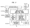
- Fig. 2 is a drawing of scanner and data processors 15 and 45 of Fig. 1 and scanner and processor 61 of Fig. 8 in greater detail.
- the operator of meter 41 may use I/O 47 to select the meter mode to place a postal indicia on mail piece 10 or the scan mode to read the postal indicia on mail piece 10.
- controller 46 turns control of meter 41 over to scan process controller 51.
- Mail piece 10 will be moved under scanner 55 and transported through meter 41 (not shown).
- Scanner 55 will store the image of mail piece 10 in buffer 52, convert the image by using the process mentioned in block 53 and store the processed image in processed mail data buffer 54. Then the optical character recognition process 53 will begin.
- Process 53 will segment the image into its various components, i.e., amount of postage, meter number, date mail piece 10 mailed, place mail piece 10 mailed, security code 89, tracking number 7, recipient address 9, and return address 8 etc.
- a recognition process will take the segmented components of the aforementioned image and convert them into an ASCII text field.
- the identification process it will be determined whether or not the ASCII information is in the correct format.
- the extracted information will be placed in processed mail data buffer 54.
- Clock and calendar 58 will be used to determine when mail piece 10 was scanned and I/O 57 will be used to convey the information stored in buffer 54 to modem 21 at predetermined times.
- the operator of meter 11 may use I/O 17 to select the meter mode to place a postal indicia on mail piece 10 or the scan mode to read the postal indicia on mail piece 10.
- controller 16 turns control of meter 11 over to meter process controller 51. While mail piece 10 is being printed it is scanned by scanner 55.
- Scanner 55 will store the image of mail piece 10 in buffer 52, while mail piece 10 is being printed by meter 11. Scanner 55 will also convert the image by using the process shown in block 53 and store the processed image in mail data buffer 54. Then, the optical character recognition process 53 will begin. Process 53 will segment the image into its various components, i.e., amount of postage, meter number, date mail piece 10 mailed, place mail piece 10 mailed, security code 89, tracking number 7, recipient address 9, and return address 8 etc. At this point the recognition process will take the segmented components of the aforementioned image and convert them into an ASCII text field. In the identification process it will be determined whether or not the ASCII information is in the correct format. Now the extracted information will be placed in processed mail data buffer 54. Clock and calendar 6 will be used to note when an indicia was affixed to mail piece 10 and when mail piece 10 was scanned. I/O 56 will be used to convey the information stored in buffer 54 to modem 20 at a predetermined time.
- the operator of mail piece opening unit 60 may use I/O 47 to open mail piece 10 and select the scan mode to read the postal indicia on mail piece 10.
- controller 64 turns control of unit 60 over to scan process controller 51.
- Mail piece 10 will be moved under scanner 55 and transported through unit 60 by opener and envelope transport 65 (Fig. 8).
- Scanner 55 will store the image of mail piece 10 in buffer 52, convert the image by using the process mentioned in block 53 and store the processed image in image in processed mail data buffer 54. Then the optical character recognition process 53 will begin.
- Process 53 will segment the image into its various components, i.e., amount of postage, meter number, date mail piece 10 mailed, place mail piece 10 mailed, security code 89, tracking number 7, recipient address 9, and return address 8 etc.
- a recognition process will take the segmented components of the aforementioned image and convert them into an ASCII text field.
- the identification process it will be determined whether or not the ASCII information is in the correct format.
- the extracted information will be placed in processed mail data buffer 54.
- Clock and calendar 66 (Fig. 8) will be used to determine when mail piece 10 was scanned and I/O 63 will be used to convey the information stored in buffer 54 to modem 21 at predetermined times.
- Fig. 3 is a drawing of a mail piece containing a postal indicia that was affixed by a electronic meter.
- Mail piece 10 has a recipient address field 9 and a sender address field 8.
- a postal indicia 36 is affixed to mail piece 10.
- Indicia 36 contains a dollar amount 85, the date 86, that postal indicia 36 was affixed to mail piece 10, the place 87 that mail piece 10 was mailed, the postal meter serial number 88, an eagle 83 a security code 89 and a tracking number 7.
- Security code 89 and tracking number 7 are unique numbers that are derived from address field 9 and information contained in the postage meter that affixed indicia 36. The manner in which security code 89 and tracking number 7 are obtained is disclosed in the Sansone et al United States Patent No. 4,831,555 entitled "Unsecured Postage Applying System".
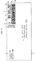
- Fig. 4 is a drawing of a mail piece 10 containing a indicia 37.
- Mail piece 10 has a recipient address field 9 and a sender address field 8.
- Mail piece 10 contains USPS Information - Based Indicia (IBI) 37.
- the United States Postal Service Engineering Center recently published a notice of proposed specification that describes a Information Based Indicia.
- the postal indicia 37 contains a dollar amount 93, the date 94, that the postal indicia was affixed to mail piece 10, the place 95 that mail piece 10 was mailed, the postal security device serial number 96, a FIM code 97; a 2D encrypted bar code 98; and a tracking number 7.
- Serial number 96 may be derived from bar code 98 or be equal to bar code 98.
- Bar code 98 is a unique number that is derived from address field 9 and information contained in the postal security device that affixed IBI 37. The manner in which information contained in bar code 98 is obtained is disclosed in the Sansone, et al. United States Patent No. 4,831,555 entitled "Unsecured Postage Applying System,".
- Mail piece 10 also contains an indication 38 of the class of mail piece 10.
- Fig. 5 is a drawing of a mail piece containing an envelope in which the indicia, senders address and recipient address were printed on labels that were affixed to the envelope or on a piece of paper that can be seen through the envelope.
- Fig. 5 is the same as Fig. 4 except that the return address field 8 is printed on a label 77, indicia 37 is printed on a label 75 and recipient address field 9 is printed on a label 76.
- Return address field 8, indicia 37, recipient address field 9 may be also printed on paper so that they may be seen through envelope 78.
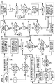
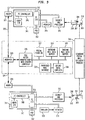
- Fig. 6 is a drawing of a flow chart of the scan/upload process for the meter/opener and PSD.
- the user selects the scan process and inserts a mail piece for the meter/opener.
- PSD 342 Fig. 9
- Block 899 processes the mail piece and sends a start process signal to the scan controller. This process is used by meter controller 46 of Fig. 1 and letter opener controller 64 of Fig. 8. Then the program goes to block 901.
- Block 906 determines whether or not the trailing edge of mail piece 10 has been sensed. If, the trailing edge of mail piece 10 has not been sensed then the program goes back to block 906. If, the trailing edge of mail piece 10 has been sensed then the program block 52 (FIG.2) to the transient image buffer block 908. Then the program goes to goes to block 907. Block 907 transfers the Nth image from the scan buffer block 909 to add the N, piece count of the image of the mail piece meter number, date and time to the header for the record. Then the program goes to block 915 to segment the image. Then the program goes to block 916 to recognize segmented images.
- Block 917 the program identifies the segmented characters. Now the program goes to block 918 to extract ASCII data fields. At this point the program goes to block 919 to transfer the data to processed buffer block 920 and clear transient buffer block 908. Now the program goes to decision block 902 and to block 920 processed image buffer. Then the program goes to decision block 925. Block 925 determines whether or not the data is correct. If, the data is incorrect, the program goes to block 940 to request a rescan. If, the data is correct the program goes to block 926 to transfer the data to the final buffer. Then the program goes to block 927 the final data records buffer. At this point the program goes to decision block 930. Decision block 930 determines whether or not data center computer 26 is requesting data. If, block 930 determines that computer 26 is requesting data then the program procedes to block 935. Block 935 reads all final data records in block 927 and transfers them to I/O 56, 57 or 63.
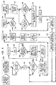
- Fig 7. is a flow chart of the upload computer mail tracking reporting program.
- the program goes to block 110 to sort all records in buffer 28 using tracker number 7 as the sortation index.
- the program goes to block 111 to sort all the records in buffer 29 using tracking number 7 as the sortation index.
- decision block 114 select the next ID record in buffer 28 . If, there are no records in buffer 28 , then the program goes to decision block 120. If, there are records in buffer 28 the program goes to decision block 115.
- Decision block 115 searches inbound mail data buffer 29 and determines whether or not it found the first tracking number match.
- decision block 115 determines that there are no ID numbers that match in buffer 29, then the program goes to block 119.
- Block 119 transfers the record to decision block 108.
- Decision block 108 determines whether or not the indicia on mail piece 10 was produced by the meter manufacturer that manufactured meter 11 or the PSD manufacturer that manufactured PSD 312.
- block 108 determines that it is not the same manufacturer, the record is transferred to other indicia buffer 109. Block 109 which holds other meter and PSD manufacturer data is emptied.
- Block 108 determines that it is the same manufacturer, the record is transferred to block 106. Block 106 holds the no match found records. If, decision block 115 finds the first tracking number match, then the program goes to block 118. Block 118 transfers record to report buffer 105. Block 105 stores the sent and received match found records.
- Block 105 and block 106 sends the reports to block 104.
- Block 104 resorts the records in buffers 105 and 106 by user (meter number or unit number) date and time. If, decision block 114 was unable to find the Nth record in buffer 28, the program goes to decision block 120.
- Decision block 120 determines whether or not all the records have been processed. If, block 120 determines that all the records have not been processed the program goes back to block 120. If, block 120 determines that all the records have been processed the program goes to decision block 124.
- Postage meter 11 includes: a funds vault 12, that represents the value of the postage that may be used by meter 11; a accounting and encryption module 13, that contains information that is used to print indicia 18; a printer 14; a scanner and processor 15; a controller 16; a clock and calendar 6; a user I/O 17, and a I/O 56.
- Accounting and encryption module 13 obtains a security code that may be obtained from address field 9 of mail piece 10 and information contained in postage meter 11.
- User I/O 17 comprises a keyboard in which an operator may enter information into meter 11 and a display in which a operator of meter 11 may read information about meter 11.
- Clock and calendar 6 provides an intemal source of time and date for controller 16.
- clock and calendar 6 will supply the instant date and time that meter 11 affixed the indicia to mail piece 10.
- Scanner and processor 15 will store the above information in buffer 54 (described in the description of Fig. 2).
- Controller 16 controls the actions of postage meter 11.
- Clock and calendar 6 also permit controller 16 to store the date and time that postal indicia 18 was affixed to mail piece 10.
- Controller 16 uses the weighing of the mail piece to determine the correct postage, and causes meter 11 to affix the correct postage to the mail piece.
- the user of meter 11 places the mail piece to be mailed on a scale (not shown) and enters the classification of the material to be mailed, i.e., first class mail, second class mail, parcel post, etc. into the keyboard of I/O 17 and relevant information regarding the object to be mailed is displayed on the display of I/O 17.
- Printer 14 will print postal indicia 18 on mail piece 10. Scanner and processor 15 scans address field 9 and sender return address field 8 of mail piece 10. Then scanner and processor 15 segments the information contained in fields 8 and 9 and stores the segmented information i.e., tracking code 7.
- Tracking code 7 may be similar to or the same as the security code determined by accounting encryption module 13. It will be obvious to one skilled in the art that there are many different methods to produce unique tracking numbers.
- I/O 56 is coupled to modem 20 and scanner and processor 15.
- Modem 23 is coupled to modem 20 via communications path 24 and modem 21 is coupled to modem 23 via communications path 25.
- Modem 23 is coupled to postage meter data center computer 26.
- Computer 26 manages the day to day operation of its postage meters metering i.e., installing new postage meters, withdrawing postage meters, and refilling postage meters with customer funds.
- Computer 26 is coupled to: postal funds data base 27.
- Data base 27 stores postal funds that have been used and credited to meters 11 and 41; outbound mail data buffer 28, that receives information about mail piece 10 from postage meter 11 i.e., tracking number 7 and address field 9; inbound mail buffer 29, that receives information about mail piece 10 from postage meter 41 i.e., tracking number 7 and address field 9; and upload data computer 30, that receives and processes information from buffers 28 and 29.
- Processed mail data base 31 is coupled to upload data computer 50.
- Processed mail data base 31 stores the result of the output of computer 30 and makes it available to computer 26 for transmission to meter 11.
- Mail piece opening unit 60 includes: a scanner and processor 61; a mail piece opener controller 64; a clock and calendar 66 that permits controller 64 to store the date and time that scanner 61 scanned mail piece 10; a user I/O 62; and a I/O 63.
- Scanner and processor 61; user I/O 62, and opener and mail piece transport 65 are coupled to controller 64.
- I/O 63 is the interface between scanner and processor 61 and modem 21 and is used to upload data from unit 60 to computer 26 via modems 21 and 23.
- Clock and calendar 66 will supply the instant date and time that scanner 61 reads mail piece 10. The above information will be stored in buffer 54 of Fig. 2.
- Opener and mail piece transport 65 will be used to open mail piece 10, if mail piece 10 is an envelope. Transport 65 is described in Luperti's United States Patent No. 3,828,634 entitled "Automatic Envelope Opener".
- unit 60 is being used as a receiving unit.
- mail piece 10 is delivered to the post and enters USPS mail delivery process 32.
- the post delivers mail piece 10 to the owner of unit 60.
- Mail piece 10 will be scanned by scanner and processor 61 of unit 60.
- Scanner and processor 61 segments the data and stores it for uploading to computer 26 via modems 21 and 23.
- Information from unit 60 regarding mail piece 10 was previously sent to computer 26 via modems 20 and 23.
- the information transmitted by unit meter 11 is tracking number 7 and address field 9.
- the information transmitted by unit 60 is tracking number 7 and address field 9, the date and time mail piece 10 was scanned by meter 41 and the serial number of meter 41.
- Fig. 9 is a block diagram of a PSD based PC mailing system.
- PC personal computer
- PC 311 includes: a PC controller 316; a user I/O 317; and a PC I/O 356.
- PSD 312 obtains a security code that may be obtained from address field 309 of mail piece 310 and information contained in PC 311.
- User I/O 317 comprises a keyboard in which an operator may enter information into PC 311 and a display in which a operator of PC 311 may read information about PC 311.
- a clock and calendar inside PSD 312 will supply the instant date and time that printer 314 affixed the indicia to mail piece 310.
- Scanner and processor 315 will store the above information in PC 311.
- Controller 316 controls the actions of PC 311. Controller 316 uses the weighing of the mail piece to determine the correct postage, and causes printer 314 to affix the correct postage to mail piece 310.
- the user of PC 311 places the mail piece to be mailed on a scale (not shown) and enters the classification of the material to be mailed, i.e., first class mail, second class mail, parcel post, etc. into the keyboard of I/O 317 and relevant information regarding the object to be mailed is displayed on the display of I/O 317.
- Printer 314 will print postal indicia 318 on mail piece 310.
- Scanner and processor 315 scans address field 309 and sender retum address field 308 of mail piece 310. Then scanner and processor 315 segments the information contained in fields 308 and 309 and stores the segmented information i.e., tracking code 307.
- Tracking code 307 may be similar to or the same as the security code determined by PSD 312. It will be obvious to one skilled in the art that there are many different methods to produce unique tracking numbers.
- I/O 356 is coupled to modem 320 and scanner and processor 315.
- Modem 323 is coupled to modem 320 via communications path 324 and modem 321 is coupled to modem 323 via communications path 325.
- Modem 323 is coupled to PSD data center computer 326.
- Computer 326 manages the day to day operation of its PSDss metering i.e., installing new PSDs, withdrawing PSDs, and refilling PSDs with customer funds.
- Computer 326 is coupled to: postal funds data base 327.
- Data base 327 stores postal funds that have been used and credited to PC 311 and 341; outbound mail data buffer 328, that receives information about mail piece 310 from PC 311 i.e., tracking number 307 and address field 309; inbound mail buffer 329, that receives information about mail piece 310 from PC 341 i.e., tracking number 307 and address field 309; and upload data computer 330, that receives and processes information from buffers 328 and 329.
- Processed mail data base 331 is coupled to upload data computer 350.
- Processed mail data base 331 stores the result of the output of computer 330 and makes it available to computer 326 for transmission to PC 311.
- PC 341 includes: a PC controller 346; user I/O 347; and PC I/O 357.
- PSD 342 is coupled to PC I/O 357.
- PC I/O is coupled to modem 321 and modem 321 is coupled to modem 323 via path 325.
- Scanner and processor 345 is coupled to PC I/O 357 and printer 344 is coupled to PC I/O 357.
- PSD 342 will supply the instant date and time that scanner 345 reads mail piece 310. The above information will be stored in PC 311.
- PC 341 is the same as PC 311.
- PC 341 is being used as the receiving PC and PC 311 is being used as a sending PC.
- PC 311 may be a receiving PC and PC 341 a sending PC and that additional PCs may be connected to computer 326.
- mail piece 310 is delivered to the post and enters USPS mail delivery process 332.
- the post delivers mail piece 310 to the owner of PC 341.
- Mail piece 310 will be scanned by scanner and processor 345 of PC 341.
- Scanner and processor 345 segments the data and stores it for uploading to computer 326 via modems 321 and 323.
- Information from PC 311 regarding mail piece 310 was previously sent to computer 326 via modems 320 and 323.
- the Information transmitted by PC 311 includes backing number 307 and address field 309.
- the information transmitted by PC 341 includes tracking number 307 and address field 309, the date and time mail piece 310 was scanned by PC 341 and the serial number of PC 341.
Abstract
Description
- The invention relates generally to the field of messaging systems and more particularly to messaging systems that utilize postage meters and a centralized or distributed data processing center.
- Historically postage meters have been mechanical and electromechanical devices that maintain through mechanical or "electronic registers" (postal security devices) an account of all postage printed and the remaining balance of prepaid postage; and print postage postmarks (indicia) that are accepted by the postal service as evidence of the prepayment of postage.
- Soon small business mailers may be able to use their desktop computer and printer to apply postage directly onto envelopes or labels while applying an address. The United States Postal Service Engineering Center recently published a notice of proposed specification that may accomplish the foregoing. The title of the specification is Information Based Indicia Program Postal Security Device Specification, dated June 13, 1996, herein incorporated by reference. The Information Based Indicia Program specification includes both proposed specifications for the new indicium and proposed specifications for a postal security device (PSD). The proposed Information - Based Indicia (IBI) consists of a two dimensional bar code containing hundreds of bytes of information about the mail piece and certain human-readable information. The indicium includes a digital signature to preclude the forgery of indicia by unauthorized parties. The postal security device is a security device that produces a cryptographic digital signature for the indicum and performs the function of postage meter registers.
- There are approximately one and a half million postage meters in use in the United States accounting for about twenty billion dollars of postage revenue annually. The United States Postal Service (USPS) is authorized to regulate the manufacture and use of postage meters. For the past several years the United States Postal Service has been actively proposing a solution to the problem of inadequate postage meter security. The United States Postal Service is also trying to solve the problem that currently available postal meter indicia are susceptible to counterfeiting. The United States Postal Service plans to solve the above problems by decertifying mechanical meters and implementing the Information - Based Indicia Program (IBIP).
- The IBIP is a United States Postal Service initiative supporting the development and implementation of a new form of postal indicia. The IBIP specification is intended to address the counterfeiting threat. An IBIP indicium substitutes for a postage stamp or as a postage meter imprint as evidence of the fact that postage has been paid on mail pieces. The Information - Based Indicia technology of the United States Postal Service offers the postal customer a way to pay for postage without stamps. Envelopes may be franked using the postal customer's personal computer, a personal computer compatible add on and the customer's printer. The PSD provides postal value storage and the link to the USPS and the manufacturer of the personal computer compatible add on. The IBI should be able to be read at any time to verify that funds have been paid.
- The United States Postal Service currently handles large volumes of normal mail, i.e., first class mail, second class mail and third class mail. The post delivers normal mail and the post and sender of normal mail are unaware of the time that the addressee received the normal mail. If, the sender of mail wants to known that the mail was delivered to a particular address and/or addressee the sender may use the posts expensive certified or registered mail service.
- This invention overcomes the disadvantages of the prior art by providing a system that indicates when normal digital postage meter mail or PSD mail is received by an addressee. The foregoing is accomplished by connecting a scanner and control software to a digital postage meter or PSD mail processor that would read incoming digitally metered mail. Instead of printing an indicia the scanner would read the already existing indicia and other information on the mail piece and then extract the sender data fields that are contained in the indicia or on the mail piece. The extracted mail data would be periodically uploaded to a data center. The data center would compare the extracted data with mail sender data that has previously been uploaded from sending meters and processors to determine the delivery time of particular mail pieces.
- In essence originating meters and PSD mail processors would upload pertinent mail piece information on addressees, pointers or other identifiers automatically and periodically to a data center. The recipient addressee of the mail piece would temporarily configure his digital postage meter or postal security device mail processor as a mail receiver so that the postage meter or mail processor would read the digital indicia that was affixed to the currently delivered incoming mail. The incoming mail would be date/time stamped, opened (optionally) and the unique identifier that was placed in the postal indicia would be read. The recipient meter or mail processor would periodically upload to the data center raw data on the unique identifiers or codes that have been received. If, the received unique identifiers or codes match with the sender unique identifiers or codes in a reasonable amount of time, as would normally be the case, the sent and received codes cancel out, or are kept for statistical information on delivery times, etc. Non-matched codes could be flagged and reported to the originator for further investigation. Thus, the data center may be able to locate mis-addressed or mis-routed mail and automatically feed back information on undelivered or undeliverable mail.
- Fig. 1 is a block diagram of this invention;
- Fig. 2 is a drawing of scanner and
data processors - Fig. 3 is a drawing of a mail piece containing a postal indicia that was affixed by a electronic meter;
- Fig. 4 is a drawing of a mail piece containing a Information - Based Indicia;
- Fig. 5 is a drawing of a mail piece containing an envelope in which the indicia, senders address, recipient address were printed on labels that were affixed to the envelope or on a piece of paper that can be seen through the envelope;
- Fig. 6 is a drawing of a flow chart of the scan/upload process;
- Fig. 7 is a drawing of a flow chart of the data center process;
- Fig. 8 is a block diagram of an alternate embodiment of this invention; and
- Fig. 9 is a block diagram of a PSD based PC mailing system.
-
- Referring now to the drawings in detail, and more particularly to Fig. 1, the
reference character 11 represents a electronic postage meter.Postage meter 11 includes: afunds vault 12, that represents the value of the postage that may be used bymeter 11; a accounting andencryption module 13, that contains information that is used to printindicia 18; aprinter 14; a scanner andprocessor 15; acontroller 16; a clock andcalendar 6; a user I/O 17, and a I/O 56. Accounting andencryption module 13 obtains a security code that may be obtained fromaddress field 9 ofmail piece 10 and information contained inpostage meter 11. The manner in which the aforementioned security code is obtained is disclosed in the Sansone et al United States Patent No. 4,831,555 entitled "Unsecured Postage Applying System" herein incorporated by reference. User I/O 17 comprises a keyboard in which an operator may enter information intometer 11 and a display in which a operator ofmeter 11 may read information aboutmeter 11.Funds vault 12, accounting andencryption module 13;indicia printer 14; scanner andprocessor 15; clock andcalendar 6; and user I/O 17 are coupled tocontroller 16. Clock andcalendar 6 provides an internal source of time and date forcontroller 16. Thus, clock andcalendar 6 will supply the instant date and time thatmeter 11 affixed the indicia tomail piece 10. Scanner andprocessor 15 will store the above information in buffer 54 (described in the description of Fig. 2). - Actions performed by
meter 11 are communicated to controller 16.Controller 16 controls the actions ofpostage meter 11, Clock andcalendar 6 also permitcontroller 16 to store the date and time thatpostal indicia 18 was affixed tomail piece 10.Controller 16 uses the weighing of the mail piece to determine the correct postage, and causesmeter 11 to affix the correct postage to the mail piece.Controller 16 is described in Wu's United States Patent No. 5,272,640 entitled "Automatic Mail-Processing Device With Full Functions". - The user of
meter 11 places the mail piece to be mailed on a scale (not shown) and enters the classification of the material to be mailed, i.e., first class mail, second class mail. parcel post, etc. into the keyboard of I/O 17 and relevant information regarding the object to be mailed is displayed on the display ofVO 17. -
Printer 14 will printpostal indicia 18 onmail piece 10. Scanner andprocessor 15scans address field 9 and senderreturn address field 8 ofmail piece 10. Then scanner andprocessor 15 segments the information contained infields tracking code 7,Tracking code 7 may be similar to or the same as the security code determined byaccounting encryption module 13. It will be obvious to one skilled in the art that there are many different methods to produce unique tracking numbers. - I/
O 56 is coupled tomodem 20 and scanner andprocessor 15.Modem 23 is coupled tomodem 20 viacommunications path 24 andmodem 21 is coupled tomodem 23 viacommunications path 25.Modem 23 is coupled to postage meterdata center computer 26.Computer 26 manages the day to day operation of its postage meters metering i.e., installing new postage meters, withdrawing postage meters, and refilling postage meters with customer funds. -
Computer 26 is coupled to: postalfunds data base 27.Data base 27 stores postal funds that have been used and credited tometers mail data buffer 28, that receives information aboutmail piece 10 frompostage meter 11 i.e., trackingnumber 7 and addressfield 9;inbound mail buffer 29, that receives information aboutmail piece 10 frompostage meter 41 i.e., trackingnumber 7 and addressfield 9; and uploaddata computer 30, that receives and processes information frombuffers mail data base 31 is coupled to uploaddata computer 30. Processedmail data base 31 stores the result of the output ofcomputer 30 and makes it available tocomputer 26 for transmission tometer 11. -
Postage meter 41 includes: afunds vault 42, that represents the value of the postage that may be used bymeter 41; a accounting andencryption module 43, that contains information that is used to print postal indicias; aprinter 44; a scanner andprocessor 45; acontroller 46; a clock andcalendar 58 that permitscontroller 46 to store the date and time thatscanner 45 scannedmail piece 10; a user I/O 47; and a I/O 57.Funds vault 42, accounting andencryption module 43;indicia printer 44; scanner andprocessor 45; anduser VO 47 are coupled tocontroller 46. I/O 57 is the interface between scanner andprocessor 45 andmodem 21 and is used to upload data frommeter 41 tocomputer 26 viamodems calendar 58 will supply the instant date and time thatscanner 45 readsmail piece 10. The above information will be stored inbuffer 54 of Fig. 2. - Thus,
meter 41 is the same asmeter 11. In thisexample meter 41 is being used as the receiving meter andmeter 11 is being used as a sending meter. It will be obvious to those skilled in the art thatmeter 11 may be a receiving meter and meter 41 a sending meter and that additional meters may be connected tocomputer 26. - After
indicia 18 is affixed to mailpiece 10 bypostage meter 11,mail piece 10 is delivered to the post and enters USPSmail delivery process 32. The post deliversmail piece 10 to the owner ofelectronic postage meter 41.Mail piece 10 will be scanned by scanner andprocessor 45 ofmeter 41. Scanner andprocessor 45 segments the data and stores it for uploading tocomputer 26 viamodems meter 11 regardingmail piece 10 was previously sent tocomputer 26 viamodems meter 11 is trackingnumber 7 and addressfield 9. The information transmitted bymeter 41 is trackingnumber 7 and addressfield 9, the date andtime mail piece 10 was scanned bymeter 41 and the serial number ofmeter 41 . - Fig. 2 is a drawing of scanner and
data processors processor 61 of Fig. 8 in greater detail. The operator ofmeter 41 may use I/O 47 to select the meter mode to place a postal indicia onmail piece 10 or the scan mode to read the postal indicia onmail piece 10. When the operator ofmeter 41 selects the scan mode,controller 46 turns control ofmeter 41 over to scanprocess controller 51.Mail piece 10 will be moved underscanner 55 and transported through meter 41 (not shown).Scanner 55 will store the image ofmail piece 10 inbuffer 52, convert the image by using the process mentioned inblock 53 and store the processed image in processedmail data buffer 54. Then the opticalcharacter recognition process 53 will begin.Process 53 will segment the image into its various components, i.e., amount of postage, meter number,date mail piece 10 mailed,place mail piece 10 mailed,security code 89, trackingnumber 7,recipient address 9, and returnaddress 8 etc. At this point a recognition process will take the segmented components of the aforementioned image and convert them into an ASCII text field. In the identification process it will be determined whether or not the ASCII information is in the correct format. Now the extracted information will be placed in processedmail data buffer 54. Clock andcalendar 58 will be used to determine whenmail piece 10 was scanned and I/O 57 will be used to convey the information stored inbuffer 54 tomodem 21 at predetermined times. - The operator of
meter 11 may use I/O 17 to select the meter mode to place a postal indicia onmail piece 10 or the scan mode to read the postal indicia onmail piece 10. When the operator ofmeter 11 selects the meter mode,controller 16 turns control ofmeter 11 over tometer process controller 51. Whilemail piece 10 is being printed it is scanned byscanner 55. -
Scanner 55 will store the image ofmail piece 10 inbuffer 52, whilemail piece 10 is being printed bymeter 11.Scanner 55 will also convert the image by using the process shown inblock 53 and store the processed image inmail data buffer 54. Then, the opticalcharacter recognition process 53 will begin.Process 53 will segment the image into its various components, i.e., amount of postage, meter number,date mail piece 10 mailed,place mail piece 10 mailed,security code 89, trackingnumber 7,recipient address 9, and returnaddress 8 etc. At this point the recognition process will take the segmented components of the aforementioned image and convert them into an ASCII text field. In the identification process it will be determined whether or not the ASCII information is in the correct format. Now the extracted information will be placed in processedmail data buffer 54. Clock andcalendar 6 will be used to note when an indicia was affixed to mailpiece 10 and whenmail piece 10 was scanned. I/O 56 will be used to convey the information stored inbuffer 54 tomodem 20 at a predetermined time. - The operator of mail piece opening unit 60 (described in the description of Fig. 8) may use I/
O 47 to openmail piece 10 and select the scan mode to read the postal indicia onmail piece 10. When the operator ofunit 60 selects the scan mode,controller 64 turns control ofunit 60 over to scanprocess controller 51.Mail piece 10 will be moved underscanner 55 and transported throughunit 60 by opener and envelope transport 65 (Fig. 8).Scanner 55 will store the image ofmail piece 10 inbuffer 52, convert the image by using the process mentioned inblock 53 and store the processed image in image in processedmail data buffer 54. Then the opticalcharacter recognition process 53 will begin.Process 53 will segment the image into its various components, i.e., amount of postage, meter number,date mail piece 10 mailed,place mail piece 10 mailed,security code 89, trackingnumber 7,recipient address 9, and returnaddress 8 etc. At this point a recognition process will take the segmented components of the aforementioned image and convert them into an ASCII text field. In the identification process it will be determined whether or not the ASCII information is in the correct format. Now the extracted information will be placed in processedmail data buffer 54. Clock and calendar 66 (Fig. 8) will be used to determine whenmail piece 10 was scanned and I/O 63 will be used to convey the information stored inbuffer 54 tomodem 21 at predetermined times. - Fig. 3 is a drawing of a mail piece containing a postal indicia that was affixed by a electronic meter.
Mail piece 10 has arecipient address field 9 and asender address field 8. Apostal indicia 36 is affixed to mailpiece 10.Indicia 36 contains adollar amount 85, thedate 86, thatpostal indicia 36 was affixed to mailpiece 10, theplace 87 that mailpiece 10 was mailed, the postal meterserial number 88, an eagle 83 asecurity code 89 and atracking number 7.Security code 89 and trackingnumber 7 are unique numbers that are derived fromaddress field 9 and information contained in the postage meter that affixedindicia 36. The manner in whichsecurity code 89 and trackingnumber 7 are obtained is disclosed in the Sansone et al United States Patent No. 4,831,555 entitled "Unsecured Postage Applying System". - Fig. 4 is a drawing of a
mail piece 10 containing aindicia 37.Mail piece 10 has arecipient address field 9 and asender address field 8.Mail piece 10 contains USPS Information - Based Indicia (IBI) 37. The United States Postal Service Engineering Center recently published a notice of proposed specification that describes a Information Based Indicia. Thepostal indicia 37 contains adollar amount 93, thedate 94, that the postal indicia was affixed to mailpiece 10, theplace 95 that mailpiece 10 was mailed, the postal security deviceserial number 96, aFIM code 97; a 2Dencrypted bar code 98; and atracking number 7.Serial number 96 may be derived frombar code 98 or be equal tobar code 98.Bar code 98 is a unique number that is derived fromaddress field 9 and information contained in the postal security device that affixedIBI 37. The manner in which information contained inbar code 98 is obtained is disclosed in the Sansone, et al. United States Patent No. 4,831,555 entitled "Unsecured Postage Applying System,".Mail piece 10 also contains anindication 38 of the class ofmail piece 10. - Fig. 5 is a drawing of a mail piece containing an envelope in which the indicia, senders address and recipient address were printed on labels that were affixed to the envelope or on a piece of paper that can be seen through the envelope. Fig. 5 is the same as Fig. 4 except that the
return address field 8 is printed on alabel 77,indicia 37 is printed on alabel 75 andrecipient address field 9 is printed on a label 76. Returnaddress field 8,indicia 37,recipient address field 9 may be also printed on paper so that they may be seen through envelope 78. - Fig. 6 is a drawing of a flow chart of the scan/upload process for the meter/opener and PSD. The user selects the scan process and inserts a mail piece for the meter/opener. For the receiving PSD 342 (Fig. 9) the user selects the scan process and inserts a mail piece into
scanner 345.Block 899 processes the mail piece and sends a start process signal to the scan controller. This process is used bymeter controller 46 of Fig. 1 andletter opener controller 64 of Fig. 8. Then the program goes to block 901.Block 901 determines whether or not the scan mode has been selected. If, the scan mode has not been selected then the program goes back to block 901. If, the scan mode has been selected the program goes to block 903 and sets N = 1. Then the program goes todecision block 902.Block 902 determines whether or not the edge ofmail piece 10 has been sensed. If, the edge ofmail piece 10 has not been sensed then the program goes back to block 902. If, the edge ofmail piece 10 has been sensed then the program goes to block 904 to set N = N + 1, where N is a piece count of the image of a mail piece. - Now the program goes to block 905 to scan
mail piece 10. At this point the program goes todecision block 906.Block 906 determines whether or not the trailing edge ofmail piece 10 has been sensed. If, the trailing edge ofmail piece 10 has not been sensed then the program goes back to block 906. If, the trailing edge ofmail piece 10 has been sensed then the program block 52 (FIG.2) to the transientimage buffer block 908. Then the program goes to goes to block 907.Block 907 transfers the Nth image from thescan buffer block 909 to add the N, piece count of the image of the mail piece meter number, date and time to the header for the record. Then the program goes to block 915 to segment the image. Then the program goes to block 916 to recognize segmented images. Inblock 917 the program identifies the segmented characters. Now the program goes to block 918 to extract ASCII data fields. At this point the program goes to block 919 to transfer the data to processedbuffer block 920 and cleartransient buffer block 908. Now the program goes to decision block 902 and to block 920 processed image buffer. Then the program goes todecision block 925.Block 925 determines whether or not the data is correct. If, the data is incorrect, the program goes to block 940 to request a rescan. If, the data is correct the program goes to block 926 to transfer the data to the final buffer. Then the program goes to block 927 the final data records buffer. At this point the program goes todecision block 930.Decision block 930 determines whether or notdata center computer 26 is requesting data. If, block 930 determines thatcomputer 26 is requesting data then the program procedes to block 935.Block 935 reads all final data records inblock 927 and transfers them to I/O - Now the program goes to block 936 to clear final data buffer records block 927. Then the program goes back to
decision block 902. - Fig 7. is a flow chart of the upload computer mail tracking reporting program. The program starts in
block 100 run. Then, the program goes to block 101 to determine whether or not there are any unsorted records in outbound mail data buffer 28 (Fig. 1). If, there are no unsorted records inbuffer 28, the program goes to block 900 and ends. If, block 101 determines that there are unsorted records inbuffer 28 , the program procedes todecision block 102.Decision block 102 determines whether or not there are any unsorted records in inbound mail data buffer 29 (Fig. 1). If, there are no unsorted records inbuffer 29 , the program goes to block 900 and ends. If, block 102 determines that there are unsorted records inbuffer 29 , the program procedes to block 103 to set N = 0. Now the program goes to block 110 to sort all records inbuffer 28 usingtracker number 7 as the sortation index. Now, the program goes to block 111 to sort all the records inbuffer 29 usingtracking number 7 as the sortation index. At this point the program goes to block 113 to set N = N + 1. Now the program goes to decision block 114 to select the next ID record inbuffer 28 . If, there are no records inbuffer 28 , then the program goes todecision block 120. If, there are records inbuffer 28 the program goes todecision block 115. Decision block 115 searches inboundmail data buffer 29 and determines whether or not it found the first tracking number match. - If,
decision block 115 determines that there are no ID numbers that match inbuffer 29, then the program goes to block 119.Block 119 transfers the record todecision block 108.Decision block 108 determines whether or not the indicia onmail piece 10 was produced by the meter manufacturer that manufacturedmeter 11 or the PSD manufacturer that manufacturedPSD 312. - If, block 108 determines that it is not the same manufacturer, the record is transferred to other indicia buffer 109.
Block 109 which holds other meter and PSD manufacturer data is emptied. - Periodically with the files being sent to each of the other manufacturers or to the post. If, block 108 determines that it is the same manufacturer, the record is transferred to block 106.
Block 106 holds the no match found records. If,decision block 115 finds the first tracking number match, then the program goes to block 118.Block 118 transfers record to reportbuffer 105.Block 105 stores the sent and received match found records. -
Block 105 and block 106 sends the reports to block 104. Block 104 resorts the records inbuffers decision block 114 was unable to find the Nth record inbuffer 28, the program goes todecision block 120.Decision block 120 determines whether or not all the records have been processed. If, block 120 determines that all the records have not been processed the program goes back to block 120. If, block 120 determines that all the records have been processed the program goes todecision block 124.Decision block 124 determines whether or not buffer 105 has data. If, block 124 determines thatbuffer 105 has no data, the program goes to block 900 and ends. If, block 124 determines thatbuffer 105 has data the program goes to block 125 to set J = 0. Where J is a record number. - Now the program goes to block 126 to set J = J + 1. Then the program goes to
decision block 127.Decision block 127 determines whether or not the Jth meter number was found inblock 105. If, block 127 determines that the Jth number was found, the program goes to block 128. For the Jth meter number found inblock 105 and block 106, block 128 reads all the records and transfers them to block 107.Block 107 compiles a final report of the record buffer. Then the program goes back to block 126 to set J = J =1. - If,
decision block 127 did not find the Jth number inblock 105 the program goes to block 200 to initiate report distribution routines. Now the program goes to block 202 to J = 0. Then the program procedes to block 203 to set J = J +1. Now the program goes todecision block 204.Decision block 204 determines whether or not the Jth number is inblock 105. If, the Jth number is not inblock 105 the program goes to block 900 and ends. If, the Jth number is inblock 105 the program goes to block 205.Block 205 produces a report for the Jth user meter or unit inblock 107. After the report is produced the program goes back to block 203 to set J = J + 1 so as to produce the next report. - Fig. 8 is a block diagram of an alternate embodiment of this invention.
Postage meter 11 includes: afunds vault 12, that represents the value of the postage that may be used bymeter 11; a accounting andencryption module 13, that contains information that is used to printindicia 18; aprinter 14; a scanner andprocessor 15; acontroller 16; a clock andcalendar 6; a user I/O 17, and a I/O 56. Accounting andencryption module 13 obtains a security code that may be obtained fromaddress field 9 ofmail piece 10 and information contained inpostage meter 11. User I/O 17 comprises a keyboard in which an operator may enter information intometer 11 and a display in which a operator ofmeter 11 may read information aboutmeter 11.Funds vault 12, accounting andencryption module 13;indicia printer 14; scanner andprocessor 15; clock andcalendar 6; and user I/O 17 are coupled tocontroller 16. Clock andcalendar 6 provides an intemal source of time and date forcontroller 16. Thus, clock andcalendar 6 will supply the instant date and time thatmeter 11 affixed the indicia to mailpiece 10. Scanner andprocessor 15 will store the above information in buffer 54 (described in the description of Fig. 2). - Actions performed by
meter 11 are communicated tocontroller 16.Controller 16 controls the actions ofpostage meter 11. Clock andcalendar 6 also permitcontroller 16 to store the date and time thatpostal indicia 18 was affixed to mailpiece 10.Controller 16 uses the weighing of the mail piece to determine the correct postage, and causesmeter 11 to affix the correct postage to the mail piece. - The user of
meter 11 places the mail piece to be mailed on a scale (not shown) and enters the classification of the material to be mailed, i.e., first class mail, second class mail, parcel post, etc. into the keyboard of I/O 17 and relevant information regarding the object to be mailed is displayed on the display of I/O 17. -
Printer 14 will printpostal indicia 18 onmail piece 10. Scanner andprocessor 15 scans addressfield 9 and sender returnaddress field 8 ofmail piece 10. Then scanner andprocessor 15 segments the information contained infields code 7.Tracking code 7 may be similar to or the same as the security code determined by accountingencryption module 13. It will be obvious to one skilled in the art that there are many different methods to produce unique tracking numbers. - I/
O 56 is coupled tomodem 20 and scanner andprocessor 15.Modem 23 is coupled tomodem 20 viacommunications path 24 andmodem 21 is coupled tomodem 23 viacommunications path 25.Modem 23 is coupled to postage meterdata center computer 26.Computer 26 manages the day to day operation of its postage meters metering i.e., installing new postage meters, withdrawing postage meters, and refilling postage meters with customer funds. -
Computer 26 is coupled to: postalfunds data base 27.Data base 27 stores postal funds that have been used and credited tometers mail data buffer 28, that receives information aboutmail piece 10 frompostage meter 11 i.e., trackingnumber 7 and addressfield 9;inbound mail buffer 29, that receives information aboutmail piece 10 frompostage meter 41 i.e., trackingnumber 7 and addressfield 9; and uploaddata computer 30, that receives and processes information frombuffers mail data base 31 is coupled to upload data computer 50. Processedmail data base 31 stores the result of the output ofcomputer 30 and makes it available tocomputer 26 for transmission tometer 11. - Mail
piece opening unit 60 includes: a scanner andprocessor 61; a mailpiece opener controller 64; a clock andcalendar 66 that permitscontroller 64 to store the date and time thatscanner 61 scannedmail piece 10; a user I/O 62; and a I/O 63. Scanner andprocessor 61; user I/O 62, and opener andmail piece transport 65 are coupled tocontroller 64. I/O 63 is the interface between scanner andprocessor 61 andmodem 21 and is used to upload data fromunit 60 tocomputer 26 viamodems calendar 66 will supply the instant date and time thatscanner 61 readsmail piece 10. The above information will be stored inbuffer 54 of Fig. 2. Opener andmail piece transport 65 will be used to openmail piece 10, ifmail piece 10 is an envelope.Transport 65 is described in Luperti's United States Patent No. 3,828,634 entitled "Automatic Envelope Opener". - Thus, in this
example unit 60 is being used as a receiving unit. Afterindicia 18 is affixed to mailpiece 10 bypostage meter 11,mail piece 10 is delivered to the post and enters USPSmail delivery process 32. The post deliversmail piece 10 to the owner ofunit 60.Mail piece 10 will be scanned by scanner andprocessor 61 ofunit 60. Scanner andprocessor 61 segments the data and stores it for uploading tocomputer 26 viamodems unit 60 regardingmail piece 10 was previously sent tocomputer 26 viamodems unit meter 11 is trackingnumber 7 and addressfield 9. The information transmitted byunit 60 is trackingnumber 7 and addressfield 9, the date andtime mail piece 10 was scanned bymeter 41 and the serial number ofmeter 41. - Fig. 9 is a block diagram of a PSD based PC mailing system. Personal computer (PC) 311 includes: a
PC controller 316; a user I/O 317; and a PC I/O 356.PSD 312 obtains a security code that may be obtained fromaddress field 309 ofmail piece 310 and information contained inPC 311. User I/O 317 comprises a keyboard in which an operator may enter information intoPC 311 and a display in which a operator ofPC 311 may read information aboutPC 311. A clock and calendar insidePSD 312 will supply the instant date and time thatprinter 314 affixed the indicia to mailpiece 310. Scanner andprocessor 315 will store the above information inPC 311. - Actions performed by
PC 311 are communicated tocontroller 316.Controller 316 controls the actions ofPC 311.Controller 316 uses the weighing of the mail piece to determine the correct postage, and causesprinter 314 to affix the correct postage to mailpiece 310. - The user of
PC 311 places the mail piece to be mailed on a scale (not shown) and enters the classification of the material to be mailed, i.e., first class mail, second class mail, parcel post, etc. into the keyboard of I/O 317 and relevant information regarding the object to be mailed is displayed on the display of I/O 317. -
Printer 314 will printpostal indicia 318 onmail piece 310. Scanner andprocessor 315 scans addressfield 309 and senderretum address field 308 ofmail piece 310. Then scanner andprocessor 315 segments the information contained infields code 307.Tracking code 307 may be similar to or the same as the security code determined byPSD 312. It will be obvious to one skilled in the art that there are many different methods to produce unique tracking numbers. - I/
O 356 is coupled tomodem 320 and scanner andprocessor 315.Modem 323 is coupled tomodem 320 viacommunications path 324 andmodem 321 is coupled tomodem 323 viacommunications path 325.Modem 323 is coupled to PSDdata center computer 326.Computer 326 manages the day to day operation of its PSDss metering i.e., installing new PSDs, withdrawing PSDs, and refilling PSDs with customer funds. -
Computer 326 is coupled to: postalfunds data base 327.Data base 327 stores postal funds that have been used and credited toPC mail data buffer 328, that receives information aboutmail piece 310 fromPC 311 i.e., trackingnumber 307 andaddress field 309;inbound mail buffer 329, that receives information aboutmail piece 310 fromPC 341 i.e., trackingnumber 307 andaddress field 309; and uploaddata computer 330, that receives and processes information frombuffers mail data base 331 is coupled to upload data computer 350. Processedmail data base 331 stores the result of the output ofcomputer 330 and makes it available tocomputer 326 for transmission toPC 311. -
PC 341 includes: aPC controller 346; user I/O 347; and PC I/O 357.PSD 342 is coupled to PC I/O 357. PC I/O is coupled tomodem 321 andmodem 321 is coupled tomodem 323 viapath 325. Scanner andprocessor 345 is coupled to PC I/O 357 andprinter 344 is coupled to PC I/O 357.PSD 342 will supply the instant date and time thatscanner 345 readsmail piece 310. The above information will be stored inPC 311. - Thus,
PC 341 is the same asPC 311. In thisexample PC 341 is being used as the receiving PC andPC 311 is being used as a sending PC. It will be obvious to those skilled in the art thatPC 311 may be a receiving PC and PC 341 a sending PC and that additional PCs may be connected tocomputer 326. - After
indicia 318 is affixed to mailpiece 310 byPC 311,mail piece 310 is delivered to the post and enters USPSmail delivery process 332. The post deliversmail piece 310 to the owner ofPC 341.Mail piece 310 will be scanned by scanner andprocessor 345 ofPC 341. Scanner andprocessor 345 segments the data and stores it for uploading tocomputer 326 viamodems PC 311 regardingmail piece 310 was previously sent tocomputer 326 viamodems PC 311 includes backingnumber 307 andaddress field 309. The information transmitted byPC 341 includes trackingnumber 307 andaddress field 309, the date andtime mail piece 310 was scanned byPC 341 and the serial number ofPC 341. - The above specification describes a new and improved system for metering incoming mail. It is realized that the above description may indicate to those skilled in the art additional ways in which the principles of this invention may be used without departing from the spirit. It is, therefore, intended that this invention be limited only by the scope of the appended claims.
Claims (23)
- A incoming mail monitoring system, said system comprises:a plurality of mailers digital units that stores unique information contained in a postal indicia of a mail piece;a plurality of recipient units that reads and stores the unique information contained in the postal indicia after the mail piece has been delivered to the recipient; anda data center that receives information stored by the mailers units and the recipients units to determine if the mail piece has been delivered.
- The system claimed in claim 1, wherein the mailers unit includes a scanner that reads the postal indicia and verifies the information contained in the postal indicia.
- The system claimed in claim 2, wherein the scanner produces a record indicating that a specific indicia was produced.
- The system claimed in claim 1, wherein the mailers unit correlates the mail piece recipient address with unique information contained in the postal indicia.
- The system claimed in claim 1, wherein the recipients unit includes a scanner that reads the postal indicia.
- The system claimed in claim 1, wherein the mailers unit includes the time and date that the postal indicia was affixed to the mail piece in the unique information contained in the postal indicia.
- The system claimed in claim 6, wherein the recipients unit stores the time and date that the recipient unit read the postal indicia.
- The system claimed in claim 7, wherein the data center further includes: means for informing the mailers unit when the mail piece was received by the recipients unit.
- The system claimed in claim 7, wherein the data center determines the amount of time that has elapsed between the time the postal indicia was affixed to the mail piece and the time that the recipient unit read the postal indicia and further includes means for informing the mailers unit of said amount of time that has elapsed between the time the postal indicia was affixed to the mail piece and the time that the recipient unit read the postal indicia.
- The system claimed in claim 7, wherein the data center determines the amount of time that has elapsed between the time the postal indicia was affixed to the mail piece and the time that the recipient unit read the postal indicia and further includes means for informing the post of the amount of time that has elapsed between the time the postal indicia was affixed to the mail piece and the time that the recipient unit read the postal indicia and means for charging the post to inform the post of said amount of time.
- The system claimed in claim 1, wherein the mailers unit and the recipients unit each includes means for automatically transmitting information to the data center at predetermined intervals.
- The system claimed in claim 1, wherein the data center further includes: means for sorting the information received from each of the mailers units and from each of the recipient units.
- The system claimed in claim 12, wherein the data center further includes: means for routing the information obtained from the recipients unit regarding mail pieces received from the mailers unit to the mailers unit and means for charging the mailers unit for receiving said routed information.
- , The system claimed in claim 13, wherein the data center further includes: means for routing the information obtained from the mailers unit regarding mail pieces received by the recipients unit to the recipients unit and means for charging the recipients unit for receiving said routed information.
- The system claimed in claim 13, wherein the data center further includes: means for crediting the mailers unit for sending information to the data center.
- The system claimed in claim 14, wherein the data center further includes: means for crediting the recipients unit for sending information to the data center.
- The system claimed in claim 1, wherein the unique information is encrypted.
- The system claimed in claim 1, wherein the mailers units are digital postage units.
- The system claimed in claim 1, wherein the mailers units are Postal Security Devices.
- The system claimed in claim 1, wherein the recipients units are digital postage units.
- The system claimed in claim 1, wherein the recipients units are Postal Security Devices.
- The system claimed in claim 1, wherein the recipient mail piece unit includes an opener to open the mail piece.
- A incoming mail monitoring system, said system comprises:a plurality of mailers digital postage meters that stores unique information contained in a postal indicia of a mail piece;a plurality of recipient addressee mail piece units that reads and stores the unique information contained in the postal indicia after the mail piece has been delivered to the recipient; anda data center that receives information stored by the mailers meters and the recipients meters to determine if the mail piece has been delivered.
Applications Claiming Priority (2)
| Application Number | Priority Date | Filing Date | Title |
|---|---|---|---|
| US924668 | 1997-09-05 | ||
| US08/924,668 US6032138A (en) | 1997-09-05 | 1997-09-05 | Metering incoming deliverable mail |
Publications (2)
| Publication Number | Publication Date |
|---|---|
| EP0901107A2 true EP0901107A2 (en) | 1999-03-10 |
| EP0901107A3 EP0901107A3 (en) | 2000-09-06 |
Family
ID=25450517
Family Applications (1)
| Application Number | Title | Priority Date | Filing Date |
|---|---|---|---|
| EP98116808A Withdrawn EP0901107A3 (en) | 1997-09-05 | 1998-09-04 | Metering incoming deliverable mail |
Country Status (3)
| Country | Link |
|---|---|
| US (1) | US6032138A (en) |
| EP (1) | EP0901107A3 (en) |
| CA (1) | CA2246592C (en) |
Cited By (6)
| Publication number | Priority date | Publication date | Assignee | Title |
|---|---|---|---|---|
| EP1047025A3 (en) * | 1999-04-23 | 2000-12-20 | Pitney Bowes Inc. | Method and apparatus for detecting misuse of postal indica |
| EP1047024A3 (en) * | 1999-04-23 | 2000-12-20 | Pitney Bowes Inc. | A system for capturing information from a postal inidcia producing device so as to produce a report covering the payment of value added taxes and fees |
| NO20035858L (en) * | 2001-07-01 | 2004-01-20 | Deutsche Post Ag | Procedure for verifying the validity of digital postage stamps |
| WO2004061779A1 (en) * | 2003-01-02 | 2004-07-22 | Deutsche Post Ag | Method and device for processing graphical information located on surfaces of postal articles |
| EP2105886A1 (en) * | 2008-03-26 | 2009-09-30 | Pitney Bowes Inc. | System and method for measuring performance of a mail network |
| WO2011110565A1 (en) | 2010-03-08 | 2011-09-15 | B.R.A.H.M.S Gmbh | Procalcitonin for the diagnosis of bacterial infections and guidance of antibiotic treatment in patients with non-specific complaints |
Families Citing this family (38)
| Publication number | Priority date | Publication date | Assignee | Title |
|---|---|---|---|---|
| US5612889A (en) * | 1994-10-04 | 1997-03-18 | Pitney Bowes Inc. | Mail processing system with unique mailpiece authorization assigned in advance of mailpieces entering carrier service mail processing stream |
| GB9702099D0 (en) * | 1997-01-31 | 1997-03-19 | Neopost Ltd | Secure communication system |
| JP3603539B2 (en) * | 1997-04-30 | 2004-12-22 | セイコーエプソン株式会社 | Image display device |
| DE19733605A1 (en) * | 1997-07-29 | 1999-02-04 | Francotyp Postalia Gmbh | Procedure for billing shipping services |
| US6253219B1 (en) * | 1997-12-23 | 2001-06-26 | Pitney Bowes Inc. | Method for utilizing the postal service address as an object in an object oriented environment |
| US6295359B1 (en) * | 1998-05-21 | 2001-09-25 | Pitney Bowes Inc. | Method and apparatus for distributing keys to secure devices such as a postage meter |
| US6275470B1 (en) * | 1999-06-18 | 2001-08-14 | Digital Island, Inc. | On-demand overlay routing for computer-based communication networks |
| US6532452B1 (en) | 1999-06-24 | 2003-03-11 | Pitney Bowes Inc. | System and method for employing digital postage marks as part of value-added services in a mailing system |
| GB0002024D0 (en) * | 2000-01-29 | 2000-03-22 | Neopost Ltd | Mail opener apparatus |
| KR100390928B1 (en) * | 2000-04-07 | 2003-07-10 | 주식회사 칼라짚미디어 | A post address service method using code image physically represented and apparatus thereof |
| US6959292B1 (en) | 2000-10-20 | 2005-10-25 | Pitney Bowes Inc. | Method and system for providing value-added services |
| AU2002235181A1 (en) * | 2000-12-15 | 2002-06-24 | United States Postal Service | Electronic postmarking without directly utilizing an electronic postmark server |
| US20050102241A1 (en) * | 2000-12-18 | 2005-05-12 | Jon Cook | Method of using personal signature as postage |
| US6826548B2 (en) | 2001-01-24 | 2004-11-30 | Return Mail, Inc. | System and method for processing returned mail |
| AU2002310369A1 (en) * | 2001-06-08 | 2002-12-23 | United States Postal Service | Method and system for cross-carrier parcel tracking |
| EP1310917A3 (en) * | 2001-09-28 | 2003-06-04 | Siemens Dematic AG | Method of providing mail piece franking |
| US6928422B2 (en) * | 2001-12-12 | 2005-08-09 | Pitney Bowes Inc. | System for accepting non life harming mail from people who are authorized to deposit mail in a receptacle |
| US7080038B2 (en) * | 2001-12-12 | 2006-07-18 | Pitney Bowes Inc. | Method and system for accepting non-harming mail at a home or office |
| US7089210B2 (en) * | 2001-12-12 | 2006-08-08 | Pitney Bowes Inc. | System for a recipient to determine whether or not they received non-life-harming materials |
| US7076466B2 (en) * | 2001-12-12 | 2006-07-11 | Pitney Bowes Inc. | System for accepting non harming mail at a receptacle |
| US7003471B2 (en) * | 2001-12-12 | 2006-02-21 | Pitney Bowes Inc. | Method and system for accepting non-toxic mail that has an indication of the mailer on the mail |
| US7543735B2 (en) | 2002-01-17 | 2009-06-09 | At&T Intellectual Property I, Lp | System and method for processing package delivery |
| US20030132296A1 (en) * | 2002-01-17 | 2003-07-17 | Silver Edward M. | System and method for processing package delivery |
| KR100422024B1 (en) * | 2002-05-29 | 2004-03-11 | 서영현 | Method for publishing postage stamp based communication network and system therefor |
| US8108322B2 (en) | 2002-07-29 | 2012-01-31 | United States Postal Services | PC postage™ service indicia design for shipping label |
| US8620821B1 (en) * | 2002-08-27 | 2013-12-31 | Pitney Bowes Inc. | Systems and methods for secure parcel delivery |
| JP2005537571A (en) * | 2002-08-29 | 2005-12-08 | ユナイテッド ステイツ ポスタル サービス | System and method for reevaluating postage of mail being processed |
| US7451119B2 (en) * | 2003-08-08 | 2008-11-11 | Lockheed Martin Corporation | System and method of identifying and sorting international mail pieces based on applied-postage adequacy in order to enhance postal service revenue protection |
| US20050138469A1 (en) * | 2003-09-19 | 2005-06-23 | Pitney Bowes Inc. | Fraud detection in a postage system |
| US7353213B2 (en) * | 2003-09-19 | 2008-04-01 | Pitney Bowes Inc. | System and method for preventing duplicate printing in a web browser |
| US7937333B2 (en) * | 2003-09-19 | 2011-05-03 | Pitney Bowes Inc. | System and method for facilitating refunds of unused postage |
| US20060293953A1 (en) | 2005-06-22 | 2006-12-28 | Nicholson G R | System and method for influencing customer behavior |
| US7742942B2 (en) | 2005-06-22 | 2010-06-22 | Excentus Corporation | System and method for discounting fuel |
| US20090248654A1 (en) * | 2008-03-26 | 2009-10-01 | Pitney Bowes Inc. | System and method for processing mail using sender and recipient networked mail processing systems |
| US7765169B2 (en) * | 2008-05-22 | 2010-07-27 | Pitney Bowes Inc. | System and method for internal processing of mail using sender and recipient networked mail processing systems |
| US8598482B2 (en) * | 2009-03-16 | 2013-12-03 | United States Postal Service | Intelligent barcode systems |
| US20100241638A1 (en) * | 2009-03-18 | 2010-09-23 | O'sullivan Patrick Joseph | Sorting contacts |
| WO2013013171A2 (en) | 2011-07-21 | 2013-01-24 | United States Postal Service | Content retrieval systems for distribution items |
Citations (2)
| Publication number | Priority date | Publication date | Assignee | Title |
|---|---|---|---|---|
| US4831555A (en) | 1985-08-06 | 1989-05-16 | Pitney Bowes Inc. | Unsecured postage applying system |
| US5272640A (en) | 1986-10-17 | 1993-12-21 | Wu Sheng J | Automatic mail-processing device with full functions |
Family Cites Families (15)
| Publication number | Priority date | Publication date | Assignee | Title |
|---|---|---|---|---|
| US4637051A (en) * | 1983-07-18 | 1987-01-13 | Pitney Bowes Inc. | System having a character generator for printing encrypted messages |
| US4641347A (en) * | 1983-07-18 | 1987-02-03 | Pitney Bowes Inc. | System for printing encrypted messages with a character generator and bar-code representation |
| US4641346A (en) * | 1983-07-21 | 1987-02-03 | Pitney Bowes Inc. | System for the printing and reading of encrypted messages |
| FR2584557B1 (en) * | 1985-07-02 | 1989-07-28 | Smh Alcatel | REMOTE CONTROL SYSTEM FOR POSTAGE MACHINES |
| US4835713A (en) * | 1985-08-06 | 1989-05-30 | Pitney Bowes Inc. | Postage meter with coded graphic information in the indicia |
| US5375172A (en) * | 1986-07-07 | 1994-12-20 | Chrosny; Wojciech M. | Postage payment system employing encryption techniques and accounting for postage payment at a time subsequent to the printing of postage |
| US4800504A (en) * | 1987-03-13 | 1989-01-24 | Pitney Bowes Inc. | Interactive outgoing and incoming mailpiece processing system |
| GB8804689D0 (en) * | 1988-02-29 | 1988-03-30 | Alcatel Business Systems | Franking system |
| US5043908A (en) * | 1989-10-03 | 1991-08-27 | Pitney Bowes Inc. | Mail delivery system with arrival monitoring |
| US5072400A (en) * | 1989-10-03 | 1991-12-10 | Pitney Bowes Inc. | Mail delivery system with package integrity monitoring |
| JP3371644B2 (en) * | 1995-09-14 | 2003-01-27 | オムロン株式会社 | Mail processing system, mail processing apparatus, reader, and host computer |
| US5635694A (en) * | 1995-09-27 | 1997-06-03 | Xerox Corporation | System and method for embedding machine coded destination information into a postal mark |
| US5770841A (en) * | 1995-09-29 | 1998-06-23 | United Parcel Service Of America, Inc. | System and method for reading package information |
| US5819241A (en) * | 1996-05-28 | 1998-10-06 | Reiter; Joshua J. | Interactive process for applying or printing information on letters or parcels |
| US5790790A (en) * | 1996-10-24 | 1998-08-04 | Tumbleweed Software Corporation | Electronic document delivery system in which notification of said electronic document is sent to a recipient thereof |
-
1997
- 1997-09-05 US US08/924,668 patent/US6032138A/en not_active Expired - Fee Related
-
1998
- 1998-09-04 EP EP98116808A patent/EP0901107A3/en not_active Withdrawn
- 1998-09-04 CA CA002246592A patent/CA2246592C/en not_active Expired - Fee Related
Patent Citations (2)
| Publication number | Priority date | Publication date | Assignee | Title |
|---|---|---|---|---|
| US4831555A (en) | 1985-08-06 | 1989-05-16 | Pitney Bowes Inc. | Unsecured postage applying system |
| US5272640A (en) | 1986-10-17 | 1993-12-21 | Wu Sheng J | Automatic mail-processing device with full functions |
Cited By (7)
| Publication number | Priority date | Publication date | Assignee | Title |
|---|---|---|---|---|
| EP1047025A3 (en) * | 1999-04-23 | 2000-12-20 | Pitney Bowes Inc. | Method and apparatus for detecting misuse of postal indica |
| EP1047024A3 (en) * | 1999-04-23 | 2000-12-20 | Pitney Bowes Inc. | A system for capturing information from a postal inidcia producing device so as to produce a report covering the payment of value added taxes and fees |
| US6509976B1 (en) | 1999-04-23 | 2003-01-21 | Pitney Bowes Inc. | System for capturing information from a postal indicia producing device so as to produce a report covering the payment of value added taxes and fees |
| NO20035858L (en) * | 2001-07-01 | 2004-01-20 | Deutsche Post Ag | Procedure for verifying the validity of digital postage stamps |
| WO2004061779A1 (en) * | 2003-01-02 | 2004-07-22 | Deutsche Post Ag | Method and device for processing graphical information located on surfaces of postal articles |
| EP2105886A1 (en) * | 2008-03-26 | 2009-09-30 | Pitney Bowes Inc. | System and method for measuring performance of a mail network |
| WO2011110565A1 (en) | 2010-03-08 | 2011-09-15 | B.R.A.H.M.S Gmbh | Procalcitonin for the diagnosis of bacterial infections and guidance of antibiotic treatment in patients with non-specific complaints |
Also Published As
| Publication number | Publication date |
|---|---|
| EP0901107A3 (en) | 2000-09-06 |
| US6032138A (en) | 2000-02-29 |
| CA2246592C (en) | 2002-12-03 |
| CA2246592A1 (en) | 1999-03-05 |
Similar Documents
| Publication | Publication Date | Title |
|---|---|---|
| CA2246592C (en) | Metering incoming deliverable mail | |
| US6064995A (en) | Metering incoming mail to detect fraudulent indicia | |
| US5925864A (en) | Metering incoming deliverable mail to automatically enable address correction | |
| US6112193A (en) | Reading encrypted data on a mail piece to cancel the mail piece | |
| US6006211A (en) | Metering incoming deliverable mail to identify delivery delays | |
| US6098057A (en) | Method and apparatus for batch mail processing with integrated scale and automatic manifest compilation | |
| US8407156B2 (en) | Closed loop postage metering system | |
| US6064994A (en) | Method and arrangement for data processing in a mail-shipping system with a postage meter machine | |
| US4796193A (en) | Postage payment system where accounting for postage payment occurs at a time subsequent to the printing of the postage and employing a visual marking imprinted on the mailpiece to show that accounting has occurred | |
| AU684998B2 (en) | Mail processing system with unique mailpiece authorization assigned in advance of mailpieces entering carrier service mail processing stream | |
| JP3924021B2 (en) | Postage payment and proof method | |
| US6834273B1 (en) | System for capturing information from a postal indicia producing device so as to correct improperly paid mail pieces | |
| CA1306812C (en) | System for processing a letter for bulk mailing | |
| US7346590B2 (en) | Method to account for domestic and international mail fees | |
| EP1062638B1 (en) | System and method for management of correspondence | |
| US20050209976A1 (en) | Mail receipt terminal having deposit tracking capability | |
| EP0845759B1 (en) | A system for the enhancement of information based indicia and postage security devices | |
| US7389274B2 (en) | Integrated payment for international business reply mail | |
| US20050228761A1 (en) | Manifesting mail for legal electronic proof of induction/acceptance | |
| EP1047024B1 (en) | A system for capturing information from a postal indicia producing device so as to produce a report covering the payment of value added taxes and fees | |
| US9165411B2 (en) | Method and system for embedding mailer specified mailing instructions on a mail piece to automate mail processing | |
| US6897973B1 (en) | System and method for management of correspondence | |
| EP1519324A2 (en) | Method for postage evidencing for the payment of terminal dues | |
| Bleumer | Industrial Offline E-Postage Systems | |
| JP2004532440A (en) | Friends mail system and method |
Legal Events
| Date | Code | Title | Description |
|---|---|---|---|
| PUAI | Public reference made under article 153(3) epc to a published international application that has entered the european phase |
Free format text: ORIGINAL CODE: 0009012 |
|
| AK | Designated contracting states |
Kind code of ref document: A2 Designated state(s): DE FR GB |
|
| AX | Request for extension of the european patent |
Free format text: AL;LT;LV;MK;RO;SI |
|
| RIN1 | Information on inventor provided before grant (corrected) |
Inventor name: SANSONE, RONALD P. Inventor name: MCFIGGANS, ROBERT B. |
|
| PUAL | Search report despatched |
Free format text: ORIGINAL CODE: 0009013 |
|
| AK | Designated contracting states |
Kind code of ref document: A3 Designated state(s): AT BE CH CY DE DK ES FI FR GB GR IE IT LI LU MC NL PT SE |
|
| AX | Request for extension of the european patent |
Free format text: AL;LT;LV;MK;RO;SI |
|
| 17P | Request for examination filed |
Effective date: 20010228 |
|
| AKX | Designation fees paid |
Free format text: DE FR GB |
|
| 17Q | First examination report despatched |
Effective date: 20071029 |
|
| STAA | Information on the status of an ep patent application or granted ep patent |
Free format text: STATUS: THE APPLICATION IS DEEMED TO BE WITHDRAWN |
|
| 18D | Application deemed to be withdrawn |
Effective date: 20080311 |