EP0901048B1 - Integrated multi-toner dispensing system - Google Patents
Integrated multi-toner dispensing system Download PDFInfo
- Publication number
- EP0901048B1 EP0901048B1 EP98113087A EP98113087A EP0901048B1 EP 0901048 B1 EP0901048 B1 EP 0901048B1 EP 98113087 A EP98113087 A EP 98113087A EP 98113087 A EP98113087 A EP 98113087A EP 0901048 B1 EP0901048 B1 EP 0901048B1
- Authority
- EP
- European Patent Office
- Prior art keywords
- toner
- dispenser
- dispensers
- image area
- gate member
- Prior art date
- Legal status (The legal status is an assumption and is not a legal conclusion. Google has not performed a legal analysis and makes no representation as to the accuracy of the status listed.)
- Expired - Lifetime
Links
Images


Classifications
-
- G—PHYSICS
- G03—PHOTOGRAPHY; CINEMATOGRAPHY; ANALOGOUS TECHNIQUES USING WAVES OTHER THAN OPTICAL WAVES; ELECTROGRAPHY; HOLOGRAPHY
- G03G—ELECTROGRAPHY; ELECTROPHOTOGRAPHY; MAGNETOGRAPHY
- G03G15/00—Apparatus for electrographic processes using a charge pattern
- G03G15/01—Apparatus for electrographic processes using a charge pattern for producing multicoloured copies
- G03G15/0105—Details of unit
- G03G15/0126—Details of unit using a solid developer
-
- G—PHYSICS
- G03—PHOTOGRAPHY; CINEMATOGRAPHY; ANALOGOUS TECHNIQUES USING WAVES OTHER THAN OPTICAL WAVES; ELECTROGRAPHY; HOLOGRAPHY
- G03G—ELECTROGRAPHY; ELECTROPHOTOGRAPHY; MAGNETOGRAPHY
- G03G15/00—Apparatus for electrographic processes using a charge pattern
- G03G15/06—Apparatus for electrographic processes using a charge pattern for developing
- G03G15/08—Apparatus for electrographic processes using a charge pattern for developing using a solid developer, e.g. powder developer
- G03G15/0822—Arrangements for preparing, mixing, supplying or dispensing developer
- G03G15/0877—Arrangements for metering and dispensing developer from a developer cartridge into the development unit
-
- G—PHYSICS
- G03—PHOTOGRAPHY; CINEMATOGRAPHY; ANALOGOUS TECHNIQUES USING WAVES OTHER THAN OPTICAL WAVES; ELECTROGRAPHY; HOLOGRAPHY
- G03G—ELECTROGRAPHY; ELECTROPHOTOGRAPHY; MAGNETOGRAPHY
- G03G15/00—Apparatus for electrographic processes using a charge pattern
- G03G15/06—Apparatus for electrographic processes using a charge pattern for developing
- G03G15/08—Apparatus for electrographic processes using a charge pattern for developing using a solid developer, e.g. powder developer
- G03G15/0896—Arrangements or disposition of the complete developer unit or parts thereof not provided for by groups G03G15/08 - G03G15/0894
- G03G15/0898—Arrangements or disposition of the complete developer unit or parts thereof not provided for by groups G03G15/08 - G03G15/0894 for preventing toner scattering during operation, e.g. seals
-
- G—PHYSICS
- G03—PHOTOGRAPHY; CINEMATOGRAPHY; ANALOGOUS TECHNIQUES USING WAVES OTHER THAN OPTICAL WAVES; ELECTROGRAPHY; HOLOGRAPHY
- G03G—ELECTROGRAPHY; ELECTROPHOTOGRAPHY; MAGNETOGRAPHY
- G03G2215/00—Apparatus for electrophotographic processes
- G03G2215/01—Apparatus for electrophotographic processes for producing multicoloured copies
- G03G2215/0167—Apparatus for electrophotographic processes for producing multicoloured copies single electrographic recording member
- G03G2215/0174—Apparatus for electrophotographic processes for producing multicoloured copies single electrographic recording member plural rotations of recording member to produce multicoloured copy
Landscapes
- Physics & Mathematics (AREA)
- General Physics & Mathematics (AREA)
- Color Electrophotography (AREA)
- Dry Development In Electrophotography (AREA)
Description
- This invention relates generally to a method and apparatus for dispensing toner in an electrophotographic machine and more particularly concerns integrating the functions of a plurality of toner dispensing mechanisms in order to reduce the number and complexity of toner dispensing mechanisms.
- In the low volume/desktop printing market, low cost, small size and simplicity of design are critical requirements. With the introduction of color printing machines, a plurality of developing stations are necessary, a developing station being associated with each colour to be developed. Currently, each developing station includes separate toner dispensing systems each having auger, mixer and gate mechanisms associated therewith to control the amount of toner dispensed to the respective developer units. It is highly desirable to reduce the number of redundant control mechanisms in order to reduce the cost and complexity of color printing machines.
- EP-A-0488146 discloses a multi-color developing device comprising a plurality of developing mechanisms to perform a developing action in individually different colours. The same number of toner containers as the number of developing mechanisms are arranged in a fixed manner, wherein toner feeding means for feeding a toner into the corresponding developing mechanism are provided.
- EP-A-0712051 discloses a system for the manufacture of three-dimensional objects from computer data using a photo-imaging station. The system comprises a toner dispensing mechanism that is as a whole movable relative to the printing medium.
- US-A-5585899 discloses an apparatus for replenishing toner in a developer unit. The apparatus comprises a plurality of toner discharge units that may selectively be energized to dispense toner into a developer unit by a commonly used auger.
- The present invention is drawn to reducing the number of toner dispenser control mechanisms in a colour printing machine having a plurality of toner dispensers. This is accomplished by an apparatus for dispensing toner having the features set out in
claim 1. According to the invention, the toner dispensers are located along a relatively straight line so that a single toner dispenser member with a single control mechanism can move toner from the toner supply to the developer units. Various toner dispenser members such as a toner moving member, a toner mixing member and a gate member can be used alone or in combination to aid in dispensing the toner from the toner dispenser. - Preferably the apparatus further comprises tracks for the gating member to move along, wherein the toner dispenser control can selectively control the alignment of the toner dispenser openings and the gate member openings. Further advantageous embodiments are defined in the dependent claims.
- According to a further aspect of the invention there is provided a method defined in claim 9 for dispensing toner comprising: locating at least two toner dispensers in close proximity to one another, each toner dispenser having a supply of toner contained therein and an opening through which toner passes from the toner dispenser; dispensing toner from the at least two toner dispensers with a toner dispenser member having at least two toner dispenser sections, each toner dispenser section having a toner dispenser associated therewith; and controlling dispensing with a toner dispenser member control whereby the toner dispenser member sections cause the toner to move when the toner dispenser member control is actuated.
- Preferably, dispensing toner form the at least two toner dispensers includes moving toner in the toner dispensers with the toner dispenser member extending between the toner dispensers which moves toner in the toner dispensers towards the openings through which toner passes from the toner dispenser.
- Preferably, locating the at least two toner dispenser includes integrally forming the toner dispensers such that each toner dispenser shares a common wall with another toner dispenser.
- Preferably the method further comprises sealing portions of the toner dispenser member which extend through the common walls between the toner dispensers, whereby the toner dispensers are sealed from one another.
- Preferably, dispensing toner includes mixing the toner with the toner dispenser member.
- Preferably the method further comprises gating the flow of toner from the toner dispensers with a gate member associated with the at least two toner dispensers, the gate member moving from an open to a closed position; the open position allowing toner to flow through the opening and the closed position blocking toner flow through the opening.
- Preferably, dispensing the toner includes mixing the toner with the toner dispenser member, or gating the flow of toner with the toner dispenser member .
- Preferably gating the flow of toner includes aligning openings in the toner dispenser member with openings in the toner dispensers when toner is to flow from the toner dispenser; and misaligning openings in the toner dispenser member with the openings in the toner dispensers when tone flow is to be stopped.
- Preferably the dispensing controlling includes moving the toner dispenser member along a track to selectively align the openings in the toner dispenser with the openings in the toner dispenser member.
- In the following, the invention is described for a preferred embodiment with reference to the drawings.
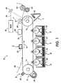
- Figure 1 is a schematic view of an electrophotographic print engine;
- Figure 2 is a schematic view of the integrated developer dispenser of the present invention;
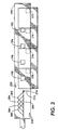
- Figure 3 is a schematic view of a particular gating member;
- Figure 4 is a view of the gating member in the full open position; and
- Figure 5 is a view of the gating member in the selectively open position.
-
- While the present invention will be described in connection with a preferred embodiment thereof, it will be understood that it is not intended to limit the invention to that embodiment. On the contrary, it is intended to cover all alternatives, modifications, and equivalents as may be included within the scope of the invention as defined by the appended claims.
- The present invention is practiced in an electrophotographic or printing machine. The embodiment shown in Figure 1 includes a plurality of individual subsystems which are organized and used so as to produce a colour image in 5 cycles, or passes, of a photoconductive member. While the 5 cycle colour electrophotographic architecture results in a 20% loss of productivity over a comparable 4 cycle colour electrophotographic architecture, the additional cycle allows for a significant size and cost reduction. Of course, the present invention can also be used in more conventional electrophotographic architectures such as 4 pass systems.
- Figure 1 illustrates a colour electrophotographic printing machine 8 which is suitable for implementing the principles of the present invention. The printing machine 8 includes a
photoreceptor belt 10 which travels in the direction indicated by thearrow 12. Belt travel is brought about by mounting the belt about a drive roller 16 (which is driven by a motor which is not shown) and atension roller 14. - As the photoreceptor belt travels each part of it passes through each of the subsequently described process stations. For convenience, a single section of the photoreceptor belt, referred to as the image area, is identified. The image area is that part of the photoreceptor belt which is to receive the toner images which, after being transferred to a substrate, produce the final colour image. While the photoreceptor belt may have numerous image areas, since each image area is processed in the same way a description of the processing of one image area suffices to fully explain the operation of the printing machine.
- As previously mentioned, the production of a complete colour print takes place in 5 cycles. The first cycle begins with the image area passing through an erase station A. At the erase station an
erase lamp 18 illuminates the image area so as to cause any residual charge which exist on the image area to be discharged. Such erase lamps and their use in erase stations are well known. Light emitting diodes are commonly used as erase lamps. - As the photoreceptor belt continues its travel the image area passes through a first charging station B. At the first charging station B a
corona generating device 20, charges the image area to a relatively high and substantially uniform potential of, for example, about -700 volts. After passing thecorona generating device 20 the image area passes through a second charging station C which partially discharges the image area to about, for example -500 volts. The second charging station C includes anAC scorotron 22. - The use of a first charging station to overcharge the image area and a subsequent second charging station to neutralize the overcharge is referred to as split charging. Since split charging is beneficial for recharging a photoreceptor which already has a developed toner layer, and since the image area does not have such a toner layer during the first cycle, split charging is not required during the first cycle. If split charging is not used either the
corona generating device 20 or thescorotron 22 corona could be used to simply charge the image area to the desired level of -500 volts. - After passing through the second charging station C the now charged image area passes through an exposure station D. At the exposure station D the charged image area is exposed to the
output 24 of a laser basedoutput scanning device 26 and which reflects from amirror 28. During the first cycle theoutput 24 illuminates the image area with a light representation of a first colour (say black) image. That light representation discharges some parts of the image area so as to create an electrostatic latent image. For example, illuminated sections of the image area might be discharged by theoutput 24 to about -50 volts. Thus, after exposure the image area has a voltage profile comprised of relatively high voltages of about -500 volts and of relatively low voltages of about -50 volts. - After passing through the exposure station D the exposed image area passes through a first development station E which deposits a first colour of negatively
charged toner 32, preferably black, onto the image area. Toner adhering to the image area is charged This causes the voltage in the illuminated area to increase by about -200 volts. Thus after development the toned parts of the image area are charged to about -250 volts while the untoned parts are charged to about -500 volts. - The developer stations could be magnetic brush developer stations, however they are preferably scavengeless developers. A benefit of scavengeless development is that it does not disturb previously developed toner layers.
- After passing through the first development station E, the image area advances so as to return to the first charging station B. The second cycle begins. The first charging station B uses its
corona generating device 20 to overcharge the image area and its first toner layer to more negative voltage levels than that which the image area and its first toner layer are to have when they are exposed. For example, the untoned parts of the image area may be charged to a potential of about -700 volts. - The voltage differences between the toned and untoned parts of the image area are substantially reduced at the second charging station C. There the
AC scorotron 22 reduces the negative charge on the image area by applying positive ions so as to charge the image area to about -500 volts. - After passing through the second charging station C the now substantially uniformly charged image area with its first toner layer advances to the exposure station D. At the exposure station D the recharged image area is again exposed to the
output 24 of a laser basedoutput scanning device 26. During this pass thescanning device 26 illuminates the image area with a light representation of a second color (say yellow) image. That light representation discharges some parts of the image area so as to create a second electrostatic latent image. The potentials on the image area after it passes through the exposure station D the second time have a potential about -500. However, the illuminated areas, both the previously toned areas and the untoned areas are discharged to about -50 volts. - After passing through the exposure station D the now exposed image area passes through a second development station F which deposits a second colour of
toner 34, yellow, onto the image area. The second development station F preferably is a scavengeless developer. - After passing through the second development station F the image area and its two toner layers returns to the first charging station B. The third cycle begins. The first charging station B again uses its
corona generating device 20 to overcharge the image area and its two toner layers to more negative voltage levels than that which the image area and its two toner layer are to have when they are exposed. The second charging station C again reduces the image area potentials to about -500 volts. The substantially uniformly charged image area with its two toner layers then advances again to the exposure station D. At exposure station D the image area is again exposed to theoutput 24 of the laser basedoutput scanning device 26. During this pass thescanning device 26 illuminates the image area with a light representation of a third colour (say magenta) image. That light representation discharges some parts of the image area so as to create a third electrostatic latent image. - After passing through the exposure station D the third time the image area passes through a third development station G. The third development station G, preferably a scavengeless developer, advances a third colour of
toner 36, magenta, onto the image area. The result is a third toner layer on the image area. - The image area with its three toner layers then advances back to the charging station B. The fourth cycle begins. The first charging station B once again uses its
corona generating device 20 to overcharge the image area (and its three toner layers) to more negative voltage levels than that which the image area is to have when it is exposed (say about -500 volts). The second charging station C once again reduces the image area potentials to about -500 volts. The substantially uniformly charged image area with its three toner layers then advances yet again to the exposure station D. At the exposure station D the recharged image area is again exposed to theoutput 24 of the laser basedoutput scanning device 26. During this pass thescanning device 26 illuminates the image area with a light representation of a fourth colour (say cyan) image. That light representation discharges some parts of the image area so as to create a fourth electrostatic latent image. - After passing through the exposure station D the fourth time the image area passes through a fourth development station H. The fourth development station, also a scavengeless developer, advances a fourth color of
toner 38, cyan, onto the image area. This marks the end of the fourth cycle. - After completing the fourth cycle the image area has four toner powder images which make up a composite color powder image. The fifth cycle begins with the image area passing the erase station A. At erase station A the erase
lamp 18 discharges the image area to a relatively low voltage level. The image area with its composite colour powder image then passes to the charging station B. During the fifth cycle the charging station B acts like a pre-transfer charging device by spraying the image area with negative ions. As the image area continues in its travel asubstrate 38 is advanced into place over the image area using a sheet feeder (which is not shown). As the image area and substrate continue their travel they pass through station C. - At station C positive ions are applied by the
scorotron 22 onto one side of thesubstrate 38. This attracts the charged toner particles from the image area onto the substrate. As the substrate continues its travel the substrate passes abias transfer roll 40 which assists in separating the substrate and the composite color powder image from thephotoreceptor belt 10. The substrate is then directed into a fuser station I where aheated fuser roll 42 and aheated pressure roller 44 create a nip through which the substrate passes. The combination of pressure and heat at the nip causes the composite colour toner image to fuse into thesubstrate 38. After fusing a chute, not shown, guides thesupport sheets 38 to a catch tray, also not shown, for removal by an operator. - After the substrate is pulled off the
photoreceptor belt 10 by thebias transfer roll 40 the image area continues its travel and eventually enters a cleaning station J. At cleaning station J acleaning blade 48 is brought into contact with the image area. The cleaning blade wipes residual toner particles from the image area. The image area then passes once again to the erase station A and the 5 cycle printing process begins again. - The various machine functions described above are generally managed and regulated by a controller which provides electrical command signals for controlling the operations described above. The controller must have information from the printing process parameters in order to accurately control the printing process.
- Figure 2 shows multiple colour toner dispensers and developer units constructed in an integrated in-
line developer module 100. Development stations E, F, G and H are part ofdeveloper module 100 and are shown as being an integrated unit, however development stations E, F, G and H may be separate, closely spaced units. Each development station has a toner dispenser, 102, 104, 106 and 108. Toner dispensers 102, 104, 106 and 108 are respectively associated withdeveloper units Common walls - In a preferred embodiment,
toner dispensers developer units - The function of the toner dispensers is to deliver toner to the developer units and to ensure that the developer material is properly mixed. Several different types of toner dispenser members will be discussed including toner moving, mixing and gate members.
Toner moving member 140, shown here in the form of an auger, is controlled by toner movingcontrol mechanism 141. The housing alignment substantial along one line enables more than two housings to share dispensing mechanisms. Toner moving member passes throughwalls Toner moving member 140 hastoner moving sections toner moving member 140 is actuated. - Dispenser wall channels with
seals toner moving member 140 to pass throughdispenser walls toner moving member 140 may be any type of seal capable of containing the toner within each toner dispenser such as mechanical wipers or magnetic seals.Toner moving member 140 can be configured to mix, as well as move the toner. Toner movingmember sections openings auger 140 in the direction shown by the arrow. The mixing portion of the auger could be made as invasive or active as needed to the point of performing a thumper function. Of course the toner mixing and moving operations may be performed by two different members rather than the combined mixing/moving member shown. -
Gate member 180 controls the flow of toner from the toner dispensers to the developing units.Gate member 180 is controlled by gatingmember controller 181. The individual gating functions of the toner dispenser can be accomplished with mechanical means using degrees of motion fewer than the number of gates to be controlled. For example, where there are n number of developer units there will be n-1 or less gate controllers.Gate member 180 is shown in the form of a plate withgate member openings toner dispenser openings Gate 180 travels back and forth depending upon the actuation of the developer units. Whengate member 180 is actuated, the gate is in the open position andgate member 180 is deactivated, the gate moves to the closed position to block the movement of the toner from the toner dispensers to the developer units. It is also possible to combine the gate and mixing/transport mechanical mechanisms because the same movement which opens the gates could provide some mixing/disturbance and/or movement/augering. - Figure 3 shows a slightly more
complex gate member 190 which allows certain colors to be skipped, depending upon the color of toner used to develop the latent images by the developer units. This gating system will more precisely control the amount of toner delivered to the developer units. The toner channel gating can be performed with thegate 190 run along atrack 200 with a gate control in the form of a single linear drive control mechanism and fixedgate pin 214.Gate 190 is run in the direction ofarrow 210 for a time/distance corresponding to the toner colour to be gated. Reversing the direction, shown byarrow 220, allows the plate to move on a track slightly sideways so thatgate member openings gate member opening 192, track 204 corresponding togate member opening 194, track 206 corresponding to gatingmember opening 196 and track 208 corresponding to gatingmember opening 198. Continued motion in the direction ofarrow 220 returns the plate to the zero position. Hence a simple timed forward and backward motion can selectively control the dispensing of four colours in the developing process. One example of the control mechanism is a timed rotating screw that can alternatively select one of four positions followed by a second mechanical movement to open the gate. -
Perpendicular track member 212 allowsgate member 190 to move in an additional direction as shown in Figure 4. Movement alongperpendicular track member 212 away fromtrack 200 allows all of thetoner dispenser openings - Figure 5 shows alignment of
toner dispenser opening 178 and gate member opening 198 so that toner is dispensed fromtoner dispenser 108.Toner dispenser openings gate member 190. - Another advantage of the integrated module is that when the entire toner supply is included, a recyclable customer replaceable unit (RCRU) is easily obtained. Bundling the toner supplies with the xerographic RCRU would have extremely beneficial unit manufacturing costs. Also, the toner dispenser unit could be removable from the developing units and only the dispenser module could be sent for refilling. Each of these toner dispensing systems have fewer control mechanisms to detach from the machine which would make these systems much simpler to remove than current removable systems.
Claims (9)
- An apparatus for dispensing toner, comprising:characterized in thatat least two toner dispensers (102, 104, 106,108), each toner dispenser having a supply of toner (132, 134, 136,138) contained therein and an opening (172, 174, 176,178) through which toner passes from the toner dispenser;toner dispenser means (140, 180, 190) associated with the toner dispensers (102, 104, 106,108), anda toner dispenser means control (141, 181, 214) for controlling movement of the toner dispenser means (140, 180, 190),
the toner dispenser means comprises a gate member (180,190). - The apparatus of claim 1, wherein the toner dispenser means comprises a toner moving member (142,144,146,148) extending between the toner dispensers which moves toner in each toner dispenser towards the opening through which toner passes from the toner dispenser.
- The apparatus as claimed in claim 1, wherein the toner dispensers (102, 104, 106,108) are integrally formed such that each toner dispenser shares a common wall (122, 124, 126) with another toner dispenser.
- The apparatus as claimed in claim 3, further comprising:toner dispenser seals (162, 164, 166, 168) surrounding portions of the toner dispenser means (140; 180; 190) which extend through the common walls (122, 124, 126) between the toner dispensers (102, 104, 106,108), whereby the toner dispensers (102, 104, 106,108) are sealed from one another.
- The apparatus of claim 2, wherein the toner dispenser means (140) is also a toner mixing member which mixes the toner in the toner dispensers (102, 104, 106,108).
- The apparatus of claim 1, wherein the gate member has at least two toner gating sections, each gating section having a toner dispenser (102, 104, 106,108) associated therewith, wherein the gate member moves from an open to a closed position; the open position allowing toner to flow through the opening (172, 174, 176,178) and the closed position blocking toner flow through the opening (172, 174, 176,178); and
wherein the apparatus further comprises a gate controller (181) for controlling the gate member (180; 190). - The apparatus of claim 1, wherein the toner dispenser means comprises a toner mixing member extending between the toner dispensers (102, 104, 106, 108) which mixes the toner in the toner dispensers (102, 104, 106,108).
- The apparatus of claim 1, wherein the gate member further comprises:gate member openings (192, 194, 196, 198) which when aligned with the openings (172, 174, 176,178) in the toner dispensers (102, 104, 106,108), allow toner to flow from the toner dispensers (102, 104, 106,108).
- A method for dispensing toner, comprising:characterized bylocating at least two toner dispensers (102, 104, 106,108) in close proximity to one another, each toner dispenser having a supply of toner (132, 134, 136,138) contained therein and an opening (172, 174, 176,178) through which toner passes from the toner dispenser;dispensing toner from the at least two toner dispensers (102, 104, 106,108)
controlling movement of a gate member (180,190) to adjust the toner flow from the at least two toner dispensers.
Applications Claiming Priority (2)
| Application Number | Priority Date | Filing Date | Title |
|---|---|---|---|
| US08/892,218 US5826150A (en) | 1997-07-14 | 1997-07-14 | Integrated multi-toner dispensing system |
| US892218 | 1997-07-14 |
Publications (3)
| Publication Number | Publication Date |
|---|---|
| EP0901048A2 EP0901048A2 (en) | 1999-03-10 |
| EP0901048A3 EP0901048A3 (en) | 2000-05-03 |
| EP0901048B1 true EP0901048B1 (en) | 2002-06-19 |
Family
ID=25399577
Family Applications (1)
| Application Number | Title | Priority Date | Filing Date |
|---|---|---|---|
| EP98113087A Expired - Lifetime EP0901048B1 (en) | 1997-07-14 | 1998-07-14 | Integrated multi-toner dispensing system |
Country Status (4)
| Country | Link |
|---|---|
| US (1) | US5826150A (en) |
| EP (1) | EP0901048B1 (en) |
| JP (1) | JPH1173003A (en) |
| DE (1) | DE69806110T2 (en) |
Families Citing this family (8)
| Publication number | Priority date | Publication date | Assignee | Title |
|---|---|---|---|---|
| JP4054521B2 (en) * | 1999-11-29 | 2008-02-27 | キヤノン株式会社 | Developer supply cartridge and developer supply system |
| JP4450205B2 (en) * | 2004-12-24 | 2010-04-14 | ブラザー工業株式会社 | Inkjet recording device |
| KR100636239B1 (en) * | 2005-06-02 | 2006-10-19 | 삼성전자주식회사 | Electrophotographic color image forming apparatus |
| JP4378374B2 (en) * | 2006-03-10 | 2009-12-02 | キヤノン株式会社 | Process cartridge, developer supply cartridge, and electrophotographic image forming apparatus |
| US7679631B2 (en) | 2006-05-12 | 2010-03-16 | Xerox Corporation | Toner supply arrangement |
| JP5375452B2 (en) * | 2009-09-01 | 2013-12-25 | コニカミノルタ株式会社 | Image forming apparatus |
| EP2534051A4 (en) * | 2010-02-08 | 2017-04-05 | Microspace Rapid PTE LTD | A micro-nozzle thruster |
| JP6932955B2 (en) * | 2017-03-16 | 2021-09-08 | 株式会社リコー | Powder storage container, process cartridge, and image forming device |
Family Cites Families (11)
| Publication number | Priority date | Publication date | Assignee | Title |
|---|---|---|---|---|
| JPS5023234A (en) * | 1973-06-28 | 1975-03-12 | ||
| US4928144A (en) * | 1987-05-31 | 1990-05-22 | Ricoh Kk | Developing device for a color image forming apparatus |
| JPH02234177A (en) * | 1989-03-08 | 1990-09-17 | Minolta Camera Co Ltd | Toner feeder |
| JPH04191869A (en) * | 1990-11-27 | 1992-07-10 | Mita Ind Co Ltd | Multicolor developing device |
| US5250993A (en) * | 1991-09-05 | 1993-10-05 | Xerox Corporation | Connection between movable developer unit and stationary toner reservoir |
| US5402222A (en) * | 1992-04-16 | 1995-03-28 | Konica Corporation | Color image forming apparatus |
| US5541720A (en) * | 1993-10-14 | 1996-07-30 | Konica Corporation | Color image forming apparatus with a process cartridge and a color developing unit |
| JPH07271168A (en) * | 1994-03-30 | 1995-10-20 | Minolta Co Ltd | Developer supplying container |
| US5442423A (en) * | 1994-06-23 | 1995-08-15 | Xerox Corporation | External development housing bearings |
| JPH08294742A (en) * | 1994-11-09 | 1996-11-12 | Texas Instr Inc <Ti> | Method and device for making prototype containing part and support |
| US5585899A (en) * | 1996-02-02 | 1996-12-17 | Xerox Corporation | Multicontainer toner dispensing apparatus |
-
1997
- 1997-07-14 US US08/892,218 patent/US5826150A/en not_active Expired - Fee Related
-
1998
- 1998-07-07 JP JP10191295A patent/JPH1173003A/en not_active Withdrawn
- 1998-07-14 EP EP98113087A patent/EP0901048B1/en not_active Expired - Lifetime
- 1998-07-14 DE DE69806110T patent/DE69806110T2/en not_active Expired - Fee Related
Also Published As
| Publication number | Publication date |
|---|---|
| JPH1173003A (en) | 1999-03-16 |
| DE69806110D1 (en) | 2002-07-25 |
| US5826150A (en) | 1998-10-20 |
| EP0901048A3 (en) | 2000-05-03 |
| DE69806110T2 (en) | 2002-10-10 |
| EP0901048A2 (en) | 1999-03-10 |
Similar Documents
| Publication | Publication Date | Title |
|---|---|---|
| EP1195652B1 (en) | Color electrophotographic apparatus | |
| US5585899A (en) | Multicontainer toner dispensing apparatus | |
| US5241356A (en) | Method and apparatus for minimizing the voltage difference between a developed electrostatic image area and a latent electrostaic non-developed image | |
| EP0918260B1 (en) | Method of controlling a duplex printing process | |
| EP0901048B1 (en) | Integrated multi-toner dispensing system | |
| US5194905A (en) | Color printer apparatus for printing selected portions of latent images in various colors | |
| US5576824A (en) | Five cycle image on image printing architecture | |
| EP0492452B1 (en) | Process for coloring an electrostatic image | |
| US4721978A (en) | Color toner concentration control system | |
| EP0635766A2 (en) | A liquid development system | |
| JPH07301967A (en) | Image forming device | |
| EP0702282B1 (en) | Image forming apparatus with a purge control means | |
| US5983041A (en) | Image recording apparatus having a neutralizing device | |
| US5862438A (en) | Reduced interdocument zone in a printing system having a single developer power supply | |
| CA2485764C (en) | Apparatus and method for cleaning a donor roll | |
| US5357318A (en) | Color image forming apparatus with interchangeable charging and transferring devices | |
| US5574541A (en) | Corona dual-use for color image formation | |
| US7660551B2 (en) | Apparatus and methods for loading a donor roll | |
| US5722008A (en) | Copy machine with physical mixing of distinct toner to form a custom colored toner | |
| US5574540A (en) | Dual use charging devices | |
| EP0547348B1 (en) | Electrophotographic color printer and method | |
| US6292645B1 (en) | Apparatus and method for minimizing the halo effect in an electrostatographic printing system | |
| US5999790A (en) | Five cycle color printing architecture with a camming mechanism for engaging and disengaging a transfer and cleaning stations | |
| EP0886192B1 (en) | Colour printing machine | |
| JP2000010401A (en) | Color image forming device and process unit used for the device |
Legal Events
| Date | Code | Title | Description |
|---|---|---|---|
| PUAI | Public reference made under article 153(3) epc to a published international application that has entered the european phase |
Free format text: ORIGINAL CODE: 0009012 |
|
| AK | Designated contracting states |
Kind code of ref document: A2 Designated state(s): DE FR GB |
|
| AX | Request for extension of the european patent |
Free format text: AL;LT;LV;MK;RO;SI |
|
| PUAL | Search report despatched |
Free format text: ORIGINAL CODE: 0009013 |
|
| AK | Designated contracting states |
Kind code of ref document: A3 Designated state(s): AT BE CH CY DE DK ES FI FR GB GR IE IT LI LU MC NL PT SE |
|
| AX | Request for extension of the european patent |
Free format text: AL;LT;LV;MK;RO;SI |
|
| RIC1 | Information provided on ipc code assigned before grant |
Free format text: 7G 03G 15/08 A, 7G 03G 15/00 B |
|
| 17P | Request for examination filed |
Effective date: 20000803 |
|
| AKX | Designation fees paid |
Free format text: DE FR GB |
|
| 17Q | First examination report despatched |
Effective date: 20010226 |
|
| GRAG | Despatch of communication of intention to grant |
Free format text: ORIGINAL CODE: EPIDOS AGRA |
|
| GRAG | Despatch of communication of intention to grant |
Free format text: ORIGINAL CODE: EPIDOS AGRA |
|
| GRAH | Despatch of communication of intention to grant a patent |
Free format text: ORIGINAL CODE: EPIDOS IGRA |
|
| GRAH | Despatch of communication of intention to grant a patent |
Free format text: ORIGINAL CODE: EPIDOS IGRA |
|
| GRAA | (expected) grant |
Free format text: ORIGINAL CODE: 0009210 |
|
| AK | Designated contracting states |
Kind code of ref document: B1 Designated state(s): DE FR GB |
|
| REG | Reference to a national code |
Ref country code: GB Ref legal event code: FG4D |
|
| REF | Corresponds to: |
Ref document number: 69806110 Country of ref document: DE Date of ref document: 20020725 |
|
| ET | Fr: translation filed | ||
| PLBE | No opposition filed within time limit |
Free format text: ORIGINAL CODE: 0009261 |
|
| STAA | Information on the status of an ep patent application or granted ep patent |
Free format text: STATUS: NO OPPOSITION FILED WITHIN TIME LIMIT |
|
| 26N | No opposition filed |
Effective date: 20030320 |
|
| REG | Reference to a national code |
Ref country code: GB Ref legal event code: 746 Effective date: 20050512 |
|
| PGFP | Annual fee paid to national office [announced via postgrant information from national office to epo] |
Ref country code: DE Payment date: 20050707 Year of fee payment: 8 |
|
| PGFP | Annual fee paid to national office [announced via postgrant information from national office to epo] |
Ref country code: FR Payment date: 20050708 Year of fee payment: 8 |
|
| PGFP | Annual fee paid to national office [announced via postgrant information from national office to epo] |
Ref country code: GB Payment date: 20050713 Year of fee payment: 8 |
|
| PG25 | Lapsed in a contracting state [announced via postgrant information from national office to epo] |
Ref country code: GB Free format text: LAPSE BECAUSE OF NON-PAYMENT OF DUE FEES Effective date: 20060714 |
|
| PG25 | Lapsed in a contracting state [announced via postgrant information from national office to epo] |
Ref country code: DE Free format text: LAPSE BECAUSE OF NON-PAYMENT OF DUE FEES Effective date: 20070201 |
|
| GBPC | Gb: european patent ceased through non-payment of renewal fee |
Effective date: 20060714 |
|
| REG | Reference to a national code |
Ref country code: FR Ref legal event code: ST Effective date: 20070330 |
|
| PG25 | Lapsed in a contracting state [announced via postgrant information from national office to epo] |
Ref country code: FR Free format text: LAPSE BECAUSE OF NON-PAYMENT OF DUE FEES Effective date: 20060731 |