EP0901018A2 - Method for quantitative measurement of a substrate - Google Patents
Method for quantitative measurement of a substrate Download PDFInfo
- Publication number
- EP0901018A2 EP0901018A2 EP98113887A EP98113887A EP0901018A2 EP 0901018 A2 EP0901018 A2 EP 0901018A2 EP 98113887 A EP98113887 A EP 98113887A EP 98113887 A EP98113887 A EP 98113887A EP 0901018 A2 EP0901018 A2 EP 0901018A2
- Authority
- EP
- European Patent Office
- Prior art keywords
- substrate
- electron mediator
- quantitative measurement
- electrode
- glucose
- Prior art date
- Legal status (The legal status is an assumption and is not a legal conclusion. Google has not performed a legal analysis and makes no representation as to the accuracy of the status listed.)
- Granted
Links
Images

Classifications
-
- C—CHEMISTRY; METALLURGY
- C12—BIOCHEMISTRY; BEER; SPIRITS; WINE; VINEGAR; MICROBIOLOGY; ENZYMOLOGY; MUTATION OR GENETIC ENGINEERING
- C12Q—MEASURING OR TESTING PROCESSES INVOLVING ENZYMES, NUCLEIC ACIDS OR MICROORGANISMS; COMPOSITIONS OR TEST PAPERS THEREFOR; PROCESSES OF PREPARING SUCH COMPOSITIONS; CONDITION-RESPONSIVE CONTROL IN MICROBIOLOGICAL OR ENZYMOLOGICAL PROCESSES
- C12Q1/00—Measuring or testing processes involving enzymes, nucleic acids or microorganisms; Compositions therefor; Processes of preparing such compositions
- C12Q1/001—Enzyme electrodes
- C12Q1/004—Enzyme electrodes mediator-assisted
-
- C—CHEMISTRY; METALLURGY
- C12—BIOCHEMISTRY; BEER; SPIRITS; WINE; VINEGAR; MICROBIOLOGY; ENZYMOLOGY; MUTATION OR GENETIC ENGINEERING
- C12Q—MEASURING OR TESTING PROCESSES INVOLVING ENZYMES, NUCLEIC ACIDS OR MICROORGANISMS; COMPOSITIONS OR TEST PAPERS THEREFOR; PROCESSES OF PREPARING SUCH COMPOSITIONS; CONDITION-RESPONSIVE CONTROL IN MICROBIOLOGICAL OR ENZYMOLOGICAL PROCESSES
- C12Q1/00—Measuring or testing processes involving enzymes, nucleic acids or microorganisms; Compositions therefor; Processes of preparing such compositions
- C12Q1/001—Enzyme electrodes
- C12Q1/005—Enzyme electrodes involving specific analytes or enzymes
- C12Q1/006—Enzyme electrodes involving specific analytes or enzymes for glucose
Definitions
- the present invention relates to a method for rapid and easy quantitative measurement of a substrate contained in a sample such as blood, urine and fruit juice with high accuracy.
- a conventional simple method for quantitating a specific component in a sample solution with no dilution or agitation of the sample solution is to cause the specific component to react with an oxidoreductase whose substrate corresponds to the specific component in the presence of an electron mediator or electron acceptor, followed by electrochemical oxidation of the electron mediator which has been reduced by this enzyme reaction, thereby to determine the oxidation current flowing during this electrochemical oxidation.
- This method normally uses a biosensor as disclosed in the Japanese Laid-Open Patent Publication Hei 3-202764.
- the biosensor is produced by first forming an electrode system having a working electrode and a counter electrode on an electrically insulating base plate by a screen printing method or the like, subsequently forming a reaction layer including an oxidoreductase and an electron mediator above the electrode system, and finally bonding a cover and a spacer to the electrically insulating base plate.
- glucose sensor will be described as an example of biosensor.
- Glucose oxidase selectively oxidizes a substrate ⁇ -D-glucose to D-glucono- ⁇ -lactone by utilizing oxygen dissolved in a sample solution as an electron mediator.
- oxygen used as the electron mediator is reduced to hydrogen peroxide.
- the glucose concentration can be quantitated either by measurement of the volume of oxygen consumed during this reaction using an oxygen electrode or by measurement of the volume of hydrogen peroxide produced using a hydrogen peroxide electrode of platinum or the like.
- this method has a drawback that the measurement is largely affected by the concentration of oxygen contained in a sample solution, depending on the measuring object.
- This system has another drawback that the system cannot function in the absence of oxygen.
- glucose sensor which includes an organic compound or a metal complex such as potassium ferricyanide, ferrocene derivatives, quinone derivatives, etc. as electron mediator, in place of oxygen.
- This biosensor can carry a known amount of glucose oxidase on an electrode system, together with an electron mediator in their stabilized state. As a result, the electrode system can be integrated with the reaction layer almost in dry state.
- Such biosensor is normally disposable and facilitates measurement of the concentration of glucose by a simple instillation of a measuring sample at a sensor chip mounted in a measurement device. Therefore, this biosensor has been attracting much attention recently.
- the substrate in a sample can be quantitated based on the current flowing across the electrodes during oxidation of the electron mediator which has been reduced by a series of enzyme reaction.
- the oxidation current value is measured with a two-electrode system comprising a working electrode and a counter electrode, then the presence of an electron mediator in oxidized state which must be reduced on the counter electrode becomes mandatory.
- the measuring sample When the measuring sample is predicted to have a low concentration of substrate, it becomes unnecessary to secure the presence of such electron mediator in oxidized state, because the amount of oxidized electron mediator to be reduced by enzyme reaction is small.
- an easy-to-oxidize substance may be present that is oxidized to induce an oxidation current at the same time when the electron mediator in reduced state is oxidized on the electrode, producing a positive error in the current value measured.
- a high concentration of substrate may vary the oxidation current value.
- the object of the present invention is therefore to provide a method for high accuracy quantitative measurement of a substrate in a wide range of substrate concentration, particularly in high substrate concentrations by suppressing the effect on the current value of a deficiency of electron mediator in oxidized state to be reduced on the counter electrode and minimizing adverse effects of an easy-to-oxidize substance on the current value.
- the present invention provides a method for quantitative measurement of a substrate comprising:
- the easy-to-oxidize substances include ascorbic acid and uric acid contained in blood. Such substances resist electrochemical reduction and would not generate reduction current.
- the adverse effect of the easy-to-oxidize substance can be minimized, thereby realizing higher accuracy quantitation of a substrate.
- the oxidation of the electron mediator in reduced state shows the rate-determining step due to a small volume of electron mediator which has been reduced by the enzyme reaction if the substrate concentration is low.
- the reduction current value therefore, increases with the increases in the substrate concentration.
- the electron mediator in oxidized state decreases as the concentration of the substrate increases, the electron mediator in oxidized state becomes deficient at a certain concentration of substrate. Therefore, in the oxidation-reduction occurring on the electrodes, the reduction of the electron mediator in oxidized state shows the rate-determining step, manifesting decreased reduction current value.
- the reduction current value during this process is an exact reflection of the amount of electron mediator in oxidized state which failed to be reduced by the enzyme reaction, thus demonstrating exceptional response characteristics to the concentration of substrate.
- an electron mediator in reduced state participates in the enzyme reaction system where the substrate is reacted with an enzyme (oxidoreductase) in the presence of an electron mediator in oxidized state, in order to render the reduction of the electron mediator in oxidized state to show the rate-determining step. Participation of electron mediator in reduced state in the enzyme reaction system facilitates high accuracy quantitation of a substrate in a wider range of substrate concentrations.
- the method for measurement of the reduction current value includes the two-electrode system having a working electrode and a counter electrode and a three-electrode system further having a reference electrode. The latter permits more accurate quantitative measurement of a substrate at higher concentrations.
- a biosensor comprising an electrode system having at least a working electrode and a counter electrode formed on an electrically insulating base plate, and a reaction layer formed on the electrode system and including at least an oxidoreductase realizes high accuracy quantitation of a specific component contained in a body sample and thus preferable.
- hydrophilic polymer in the reaction layer is preferable because it is helpful for preventing adsorption of protein or the like in the sample onto the surface of the electrode system.
- Coating of the surface of the reaction layer with a layer containing lipid helps smooth supply of a sample to the reaction layer. This lipid coating may be applied if occasion demands.
- a pH buffer may further be included in the reaction layer in order to increase the enzyme activity in the reaction layer.
- Applicable oxidoreductase may be exemplified as glucose oxidase, glucose dehydrogenase, lactate oxidase, lactate dehydrogenase, uricase, fructose dehydrogenase, alcohol oxidase, cholesterol oxidase, xanthine oxidase, amino acid oxidase and the like.
- a combination of plural oxidoreductases may also be used, such as glucose oxidase plus invertase, glucose oxidase plus invertase plus mutarotase, fructose dehydrogenase plus invertase, or the like.
- the electron mediator potassium ferricyanide, p-benzoquinone, phenazine methosulfate, methylene blue, ferrocene derivatives, or the like may be used.
- oxygen for electron mediator can yield a similar sensor response.
- Those electron mediators are used singly or in combination (a combination of two or more).
- Applicable hydrophilic polymer may be exemplified as carboxymethyl cellulose, polyvinyl pyrrolidone, polyvinyl alcohol, gelatin and its derivative, a polymer of acrylic acid or an acrylate, a polymer of methacrylic acid or a methacrylate, starch and its derivative, a polymer of maleic anhydride or a maleate, cellulose derivatives such as hydroxypropyl cellulose, methyl cellulose, ethyl cellulose, hydroxyethyl cellulose, ethylhydroxyethyl cellulose, carboxymethylethyl cellulose or the like, polyamino acid such as polylysine, and polystyrene sulfonate.
- carboxymethyl cellulose, hydroxyethyl cellulose, hydroxypropyl cellulose, methyl cellulose, ethyl cellulose, ethylhydroxyethyl cellulose and carboxymethylethyl cellulose are preferred.
- Polyamino acid such as polylysine, polyvinyl alcohol and polystyrene sulfonate may also be used preferably.
- any amphipathic phospholipid such as lecithin, phosphatidylcholine, phosphatidylethanolamine or the like may be used preferably.
- the pH buffer may be exemplified as potassium dihydrogen phosphate-dipotassium phosphate, potassium dihydrogen phosphate-disodium phosphate, sodium dihydrogen phosphate-dipotassium phosphate, sodium dihydrogen phosphate-disodium phosphate, citric acid-disodium phosphate, citric acid-dipotassium phosphate, citric acid-trisodium citrate, citric acid-tripotassium citrate, potassium dihydrogen citrate-sodium hydroxide, sodium dihydrogen citrate-sodium hydroxide, sodium hydrogen maleate-sodium hydroxide, potassium hydrogen phthalate-sodium hydroxide, succinic acid-sodium tetraborate, maleic acid-tris(hydroxymethyl)aminomethane, tris(hydroxymethyl)aminomethane-tris(hydroxymethyl)aminomethane hydrochloride, [N-(2-hydroxyethyl)piperazine-N'-2
- Those enzymes and electron mediators may be dissolved in a sample solution or otherwise isolated from the sample solution by fixing the enzyme layer containing those constituents to the base plate so as to avoid their direct dissolution in the sample solution. If the latter configuration is selected, it is preferable for the reaction layer to further include a hydrophilic polymer.
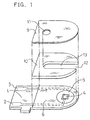
- FIG. 1 shows an exploded perspective view of a two-electrode system glucose sensor with an omission of the reaction layer.
- a silver paste is printed on an electrically insulating base plate 1 of polyethylene terephthalate by the screen printing method so as to form leads 2 and 3 on the base plate 1.
- a conductive carbon paste containing a resin binder is printed on the base plate 1 so as to form a working electrode 4.
- the working electrode 4 is in contact with the lead 2.
- an electrically insulating layer 6 is further formed on the base plate 1 by printing thereon an insulating paste.
- the electrically insulating layer 6 covers the periphery of the working electrode 4 so as to hold the exposed area of the working electrode 4 constant.
- a conductive carbon paste containing a resin binder is printed on the base plate 1 so as to cause the carbon paste to contact the previously formed lead 3, which formed a ring-like counter electrode 5.
- the electrically insulating base plate 1, a cover 9 having an air vent 11 and a spacer 10 are bonded to each other in a positional relationship as shown by the dotted chain line in FIG. 1, which gives a biosensor used as a glucose sensor.
- the spacer 10 has a slit 13 for forming a sample supply path between the base plate and the cover.
- Numeral 12 corresponds to an opening of the sample supply path.
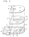
- FIG. 2 shows an exploded perspective view of a three-electrode system glucose sensor with an omission of the reaction layer.
- This glucose sensor has the same configuration as that of FIG. 1, except that the glucose sensor further comprises a reference electrode 15 made of a carbon paste formed outside the periphery of the counter electrode 5 so as to be exposed from the electrically insulating layer 6, and a lead 14 for the reference electrode.
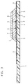
- FIG. 3 is a longitudinal cross-sectional view showing the vital part of a biosensor used in one example for application of the present invention, with an omission of the spacer and the cover.
- a reaction layer 7 including an enzyme and an electron mediator is formed on the electrically insulating base plate 1 above which the electrode system has been formed as shown in FIG. 1, and a lecithin layer 8 is further formed on the reaction layer 7.
- the reaction layer was formed by dropping a mixed aqueous solution of glucose oxidase (EC1.1.3.4; hereinafter referred to as "GOD") with potassium ferricyanide on the electrode system formed on the base plate 1 in FIG. 1 and drying it.
- GOD glucose oxidase
- the lecithin layer was formed by dropping a toluene solution of lecithin on the reaction layer and drying it.
- the cover 9 and the spacer 10 were then bonded to the base plate 1 in a positional relationship shown by the dotted line in FIG. 1, which gave a glucose sensor used in this example.
- Glucose standard solutions at various concentrations were then formulated as sample solutions. Each of those aqueous glucose standard solutions (3 ⁇ l) was supplied to the glucose sensor from the opening 12 of the sample supply path. The sample solution advanced to the air vent 11 and dissolved the reaction layer 7 and the lecithin layer above the electrode system. Upon dissolution of the reaction layer 7, enzyme reaction where glucose contained in the sample solution is oxidized to gluconolactone by the GOD will take place. This enzyme reaction accompanies at the same time reduction of the potassium ferricyanide to potassium ferrocyanide to produce ferrocyanide ions.
- FIG. 4 shows the sensor responses to the various aqueous glucose standard solutions by defining the current value at a glucose concentration of about 700 mg/dl as 100%.
- the sensor response showed linear increases with the increases in the glucose concentrations in a range of 0 to 700 mg/dl. This suggests the rate-determining step of the oxidation of the potassium ferrocyanide on the counter electrode due to small amounts of ferrocyanide ions produced by the enzyme reaction.
- the sensor response decreased as the glucose concentrations increased above 700 mg/dl. This indicates the rate-determining step of the reduction of the ferricyanide ions on the working electrode because of sufficiently large amounts of the ferrocyanide ions produced by the enzyme reaction.
- the senor showed excellent response characteristics irrespective of the glucose (substrate) concentrations.
- CMC carboxymethyl cellulose
- a glucose sensor was produced in the same manner as in Example 1 and evaluated for its responses to various aqueous glucose standard solutions as formulated in Example 1. The sensor showed similar response characteristics to those of Example 1, with less variations.
- the CMC layer was formed similarly by dropping an aqueous CMC solution on the electrode system above the base plate 1 in FIG. 1 and drying it. Then, a mixed aqueous solution of GOD, potassium ferricyanide and potassium ferrocyanide was dropped on the CMC layer and dried to form the reaction layer.
- a glucose sensor was produced in the same manner as in Example 1 and evaluated for its responses to various aqueous glucose standard solutions as formulated in Example 1.
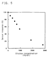
- FIG. 5 summarizes the sensor responses to the various aqueous glucose standard solutions by defining the responsive current value to a solution including 0 mg/dl glucose as 100%.
- the sensor response decreased as the glucose concentrations increased.
- the reason is that because potassium ferrocyanide coexisted in the reaction layer, the ferrocyanide ions to be oxidized on the counter electrode were always secured sufficiently, which ensured the rate-determining step of the reduction of ferricyanide ions on the working electrode even if the concentration of the substrate is low.
- the sensor showed excellent response characteristics irrespective of the glucose (substrate) concentrations.
- the CMC layer was formed by dropping an aqueous CMC solution on the electrode system above the electrically insulating base plate 1 in FIG. 2, while avoiding the reference electrode 15, and drying it. Then, a mixed aqueous solution of GOD and potassium ferricyanide was dropped on the CMC layer and dried to form the reaction layer, above which a toluene solution of lecithin was dropped and dried to form thereon the lecithin layer.
- Each of the various aqueous glucose standard solutions (3 ⁇ l) formulated in Example 1 was supplied from the opening 12 of the sample supply path.
- a voltage was applied onto the working electrode at a potential of -0.8 V using the reference electrode 15 as standard. And, 5 seconds after the voltage application, the current flowing across the working electrode 4 and the counter electrode 5 was measured.
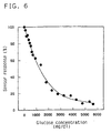
- FIG. 6 summarizes the sensor responses to the various aqueous glucose standard solutions by defining the responsive current value to a solution including 0 mg/dl glucose as 100%.
- the senor showed excellent response characteristics in a wide range of glucose (substrate) concentrations, permitting quantitation up to 6,000 mg/dl or so.
- a glucose sensor was produced in the same manner as in Example 4.
- Example 4 the sensor was evaluated for its responses in the same manner as in Example 4 except for the use of various aqueous glucose standard solutions formulated in Example 1 further containing known amounts of ascorbic acid as sample solutions.
- the sensor showed substantially identical responses to those of the glucose sensor in Example 4 despite the presence of ascorbic acid, thus demonstrating excellent response characteristics.
- the concentration of a substrate can be quantitated with high accuracy in a wide range of substrate concentrations, particularly in high substrate concentrations.
Abstract
Description
- The present invention relates to a method for rapid and easy quantitative measurement of a substrate contained in a sample such as blood, urine and fruit juice with high accuracy.
- A conventional simple method for quantitating a specific component in a sample solution with no dilution or agitation of the sample solution is to cause the specific component to react with an oxidoreductase whose substrate corresponds to the specific component in the presence of an electron mediator or electron acceptor, followed by electrochemical oxidation of the electron mediator which has been reduced by this enzyme reaction, thereby to determine the oxidation current flowing during this electrochemical oxidation.
- This method normally uses a biosensor as disclosed in the Japanese Laid-Open Patent Publication Hei 3-202764.
- The biosensor is produced by first forming an electrode system having a working electrode and a counter electrode on an electrically insulating base plate by a screen printing method or the like, subsequently forming a reaction layer including an oxidoreductase and an electron mediator above the electrode system, and finally bonding a cover and a spacer to the electrically insulating base plate.
- With this biosensor, various specific components can be quantitated by varying the oxidoreductase.
- Here, a glucose sensor will be described as an example of biosensor.
- Conventionally known method for quantitative measurement of glucose is a system comprising a combination of glucose oxidase with an oxygen electrode or a hydrogen peroxide electrode (e.g., "Biosensor", ed. by Shuichi Suzuki, Kodansha, Japan).
- Glucose oxidase selectively oxidizes a substrate β-D-glucose to D-glucono-δ-lactone by utilizing oxygen dissolved in a sample solution as an electron mediator. When the substrate is oxidized by the glucose oxidase, the oxygen used as the electron mediator is reduced to hydrogen peroxide. The glucose concentration can be quantitated either by measurement of the volume of oxygen consumed during this reaction using an oxygen electrode or by measurement of the volume of hydrogen peroxide produced using a hydrogen peroxide electrode of platinum or the like.
- However, this method has a drawback that the measurement is largely affected by the concentration of oxygen contained in a sample solution, depending on the measuring object. This system has another drawback that the system cannot function in the absence of oxygen.
- To overcome these problems, a type of glucose sensor has been developed which includes an organic compound or a metal complex such as potassium ferricyanide, ferrocene derivatives, quinone derivatives, etc. as electron mediator, in place of oxygen.
- This biosensor can carry a known amount of glucose oxidase on an electrode system, together with an electron mediator in their stabilized state. As a result, the electrode system can be integrated with the reaction layer almost in dry state.
- Such biosensor is normally disposable and facilitates measurement of the concentration of glucose by a simple instillation of a measuring sample at a sensor chip mounted in a measurement device. Therefore, this biosensor has been attracting much attention recently.
- As described above, the substrate in a sample can be quantitated based on the current flowing across the electrodes during oxidation of the electron mediator which has been reduced by a series of enzyme reaction.
- If the oxidation current value is measured with a two-electrode system comprising a working electrode and a counter electrode, then the presence of an electron mediator in oxidized state which must be reduced on the counter electrode becomes mandatory.
- When the measuring sample is predicted to have a low concentration of substrate, it becomes unnecessary to secure the presence of such electron mediator in oxidized state, because the amount of oxidized electron mediator to be reduced by enzyme reaction is small.
- However, when the measuring sample is predicted to have a high concentration of substrate, most of the electron mediator in oxidized state is reduced by enzyme reaction, resulting in a deficiency of oxidized electron mediator which can be reduced on the counter electrode. This renders the reduction on the counter electrode to show a rate-determining step, affecting the resultant current value.
- Moreover, depending on sample, an easy-to-oxidize substance may be present that is oxidized to induce an oxidation current at the same time when the electron mediator in reduced state is oxidized on the electrode, producing a positive error in the current value measured. Furthermore, a high concentration of substrate may vary the oxidation current value.
- The object of the present invention is therefore to provide a method for high accuracy quantitative measurement of a substrate in a wide range of substrate concentration, particularly in high substrate concentrations by suppressing the effect on the current value of a deficiency of electron mediator in oxidized state to be reduced on the counter electrode and minimizing adverse effects of an easy-to-oxidize substance on the current value.
- The present invention provides a method for quantitative measurement of a substrate comprising:
- a first step for causing a substrate contained in a sample to react with a specific oxidoreductase to the substrate in the presence of an electron mediator in oxidized state, and
- a second step for electrochemically reducing the electron mediator in oxidized state which remains non-reduced by the enzyme reaction in the first step, thereby obtaining a current flowing during the electrochemical reduction.
-
- While the novel features of the invention are set forth particularly in the appended claims, the invention, both as to organization and content, will be better understood and appreciated, along with other objects and features thereof, from the following detailed description taken in conjunction with the drawings.
-
- FIG. 1 is an exploded perspective view of a two-electrode system glucose sensor with an omission of the reaction layer in one example to which the present invention has been applied.
- FIG. 2 is an exploded perspective view of a three-electrode system glucose sensor with an omission of the reaction layer in one example to which the present invention has been applied.
- FIG. 3 is a longitudinal cross-sectional view of the vital part of the same glucose sensor from which the spacer and the cover have been omitted.
- FIG. 4 illustrates the characteristics of the response of a two-electrode system glucose sensor to various glucose standard solutions in one example to which the present invention has been applied.
- FIG. 5 illustrates the characteristics of the response of a two-electrode system glucose sensor to various glucose standard solutions in another example to which the present invention has been applied.
- FIG. 6 illustrates the characteristics of the response of a three-electrode system glucose sensor to various glucose standard solutions in another example to which the present invention has been applied.
-
- The easy-to-oxidize substances include ascorbic acid and uric acid contained in blood. Such substances resist electrochemical reduction and would not generate reduction current.
- Therefore, by the method where the substrate concentration is quantitated by reducing electron mediator in oxidized state which remains non-reduced by a series of enzyme reaction and reading the resultant reduction current flowing during the reduction process, the adverse effect of the easy-to-oxidize substance can be minimized, thereby realizing higher accuracy quantitation of a substrate.
- From the aspect of the oxidation-reduction occurring on the electrodes, if the two-electrode system is applied for measurement of the reduction current value, the oxidation of the electron mediator in reduced state shows the rate-determining step due to a small volume of electron mediator which has been reduced by the enzyme reaction if the substrate concentration is low. The reduction current value, therefore, increases with the increases in the substrate concentration.
- Since the electron mediator in oxidized state decreases as the concentration of the substrate increases, the electron mediator in oxidized state becomes deficient at a certain concentration of substrate. Therefore, in the oxidation-reduction occurring on the electrodes, the reduction of the electron mediator in oxidized state shows the rate-determining step, manifesting decreased reduction current value.
- The reduction current value during this process is an exact reflection of the amount of electron mediator in oxidized state which failed to be reduced by the enzyme reaction, thus demonstrating exceptional response characteristics to the concentration of substrate.
- Even at low substrate concentrations, it is preferred that an electron mediator in reduced state participates in the enzyme reaction system where the substrate is reacted with an enzyme (oxidoreductase) in the presence of an electron mediator in oxidized state, in order to render the reduction of the electron mediator in oxidized state to show the rate-determining step. Participation of electron mediator in reduced state in the enzyme reaction system facilitates high accuracy quantitation of a substrate in a wider range of substrate concentrations.
- The method for measurement of the reduction current value includes the two-electrode system having a working electrode and a counter electrode and a three-electrode system further having a reference electrode. The latter permits more accurate quantitative measurement of a substrate at higher concentrations.
- Application of the method for quantitative measurement of a substrate in accordance with the present invention to a biosensor comprising an electrode system having at least a working electrode and a counter electrode formed on an electrically insulating base plate, and a reaction layer formed on the electrode system and including at least an oxidoreductase realizes high accuracy quantitation of a specific component contained in a body sample and thus preferable.
- Further inclusion of a hydrophilic polymer in the reaction layer is preferable because it is helpful for preventing adsorption of protein or the like in the sample onto the surface of the electrode system.
- Coating of the surface of the reaction layer with a layer containing lipid helps smooth supply of a sample to the reaction layer. This lipid coating may be applied if occasion demands.
- A pH buffer may further be included in the reaction layer in order to increase the enzyme activity in the reaction layer.
- Applicable oxidoreductase may be exemplified as glucose oxidase, glucose dehydrogenase, lactate oxidase, lactate dehydrogenase, uricase, fructose dehydrogenase, alcohol oxidase, cholesterol oxidase, xanthine oxidase, amino acid oxidase and the like.
- A combination of plural oxidoreductases may also be used, such as glucose oxidase plus invertase, glucose oxidase plus invertase plus mutarotase, fructose dehydrogenase plus invertase, or the like.
- As the electron mediator, potassium ferricyanide, p-benzoquinone, phenazine methosulfate, methylene blue, ferrocene derivatives, or the like may be used. The use of oxygen for electron mediator can yield a similar sensor response. Those electron mediators are used singly or in combination (a combination of two or more).
- Applicable hydrophilic polymer may be exemplified as carboxymethyl cellulose, polyvinyl pyrrolidone, polyvinyl alcohol, gelatin and its derivative, a polymer of acrylic acid or an acrylate, a polymer of methacrylic acid or a methacrylate, starch and its derivative, a polymer of maleic anhydride or a maleate, cellulose derivatives such as hydroxypropyl cellulose, methyl cellulose, ethyl cellulose, hydroxyethyl cellulose, ethylhydroxyethyl cellulose, carboxymethylethyl cellulose or the like, polyamino acid such as polylysine, and polystyrene sulfonate.
- Among them, carboxymethyl cellulose, hydroxyethyl cellulose, hydroxypropyl cellulose, methyl cellulose, ethyl cellulose, ethylhydroxyethyl cellulose and carboxymethylethyl cellulose are preferred. Polyamino acid such as polylysine, polyvinyl alcohol and polystyrene sulfonate may also be used preferably.
- As the lipid, any amphipathic phospholipid such as lecithin, phosphatidylcholine, phosphatidylethanolamine or the like may be used preferably.
- The pH buffer may be exemplified as potassium dihydrogen phosphate-dipotassium phosphate, potassium dihydrogen phosphate-disodium phosphate, sodium dihydrogen phosphate-dipotassium phosphate, sodium dihydrogen phosphate-disodium phosphate, citric acid-disodium phosphate, citric acid-dipotassium phosphate, citric acid-trisodium citrate, citric acid-tripotassium citrate, potassium dihydrogen citrate-sodium hydroxide, sodium dihydrogen citrate-sodium hydroxide, sodium hydrogen maleate-sodium hydroxide, potassium hydrogen phthalate-sodium hydroxide, succinic acid-sodium tetraborate, maleic acid-tris(hydroxymethyl)aminomethane, tris(hydroxymethyl)aminomethane-tris(hydroxymethyl)aminomethane hydrochloride, [N-(2-hydroxyethyl)piperazine-N'-2-ethanesulfonic acid]-sodium hydroxide, [N-tris(hydroxymethyl)methyl-2-aminoethanesulfonic acid]-sodium hydroxide, [piperazine-N,N'-bis(2-ethanesulfonic acid)]-sodium hydroxide and the like.
- Those enzymes and electron mediators may be dissolved in a sample solution or otherwise isolated from the sample solution by fixing the enzyme layer containing those constituents to the base plate so as to avoid their direct dissolution in the sample solution. If the latter configuration is selected, it is preferable for the reaction layer to further include a hydrophilic polymer.
- In the following, the present invention will be described more specifically referring to concrete embodiments.
- FIG. 1 shows an exploded perspective view of a two-electrode system glucose sensor with an omission of the reaction layer. A silver paste is printed on an electrically insulating
base plate 1 of polyethylene terephthalate by the screen printing method so as to form leads 2 and 3 on thebase plate 1. Subsequently, a conductive carbon paste containing a resin binder is printed on thebase plate 1 so as to form a workingelectrode 4. The workingelectrode 4 is in contact with thelead 2. Then, an electrically insulatinglayer 6 is further formed on thebase plate 1 by printing thereon an insulating paste. The electrically insulatinglayer 6 covers the periphery of the workingelectrode 4 so as to hold the exposed area of the workingelectrode 4 constant. Thereafter, a conductive carbon paste containing a resin binder is printed on thebase plate 1 so as to cause the carbon paste to contact the previously formedlead 3, which formed a ring-like counter electrode 5. - Then, the electrically insulating
base plate 1, acover 9 having anair vent 11 and aspacer 10 are bonded to each other in a positional relationship as shown by the dotted chain line in FIG. 1, which gives a biosensor used as a glucose sensor. Thespacer 10 has aslit 13 for forming a sample supply path between the base plate and the cover.Numeral 12 corresponds to an opening of the sample supply path. - FIG. 2 shows an exploded perspective view of a three-electrode system glucose sensor with an omission of the reaction layer. This glucose sensor has the same configuration as that of FIG. 1, except that the glucose sensor further comprises a
reference electrode 15 made of a carbon paste formed outside the periphery of thecounter electrode 5 so as to be exposed from the electrically insulatinglayer 6, and alead 14 for the reference electrode. - FIG. 3 is a longitudinal cross-sectional view showing the vital part of a biosensor used in one example for application of the present invention, with an omission of the spacer and the cover.
- A
reaction layer 7 including an enzyme and an electron mediator is formed on the electrically insulatingbase plate 1 above which the electrode system has been formed as shown in FIG. 1, and a lecithin layer 8 is further formed on thereaction layer 7. - In this example, the reaction layer was formed by dropping a mixed aqueous solution of glucose oxidase (EC1.1.3.4; hereinafter referred to as "GOD") with potassium ferricyanide on the electrode system formed on the
base plate 1 in FIG. 1 and drying it. Then, the lecithin layer was formed by dropping a toluene solution of lecithin on the reaction layer and drying it. - The
cover 9 and thespacer 10 were then bonded to thebase plate 1 in a positional relationship shown by the dotted line in FIG. 1, which gave a glucose sensor used in this example. - Glucose standard solutions at various concentrations were then formulated as sample solutions. Each of those aqueous glucose standard solutions (3 µl) was supplied to the glucose sensor from the
opening 12 of the sample supply path. The sample solution advanced to theair vent 11 and dissolved thereaction layer 7 and the lecithin layer above the electrode system. Upon dissolution of thereaction layer 7, enzyme reaction where glucose contained in the sample solution is oxidized to gluconolactone by the GOD will take place. This enzyme reaction accompanies at the same time reduction of the potassium ferricyanide to potassium ferrocyanide to produce ferrocyanide ions. - When a certain time had lapsed after supply of the sample solution, a voltage of -1.0 V was applied to the working electrode with reference to the
counter electrode 5, which induced reduction of the potassium ferricyanide on the working electrode and oxidation of the potassium ferrocyanide on the counter electrode to generate a current flow across the electrodes. The current flowing during this oxidation-reduction was read 5 seconds after application of the voltage. - FIG. 4 shows the sensor responses to the various aqueous glucose standard solutions by defining the current value at a glucose concentration of about 700 mg/dl as 100%.
- The sensor response showed linear increases with the increases in the glucose concentrations in a range of 0 to 700 mg/dl. This suggests the rate-determining step of the oxidation of the potassium ferrocyanide on the counter electrode due to small amounts of ferrocyanide ions produced by the enzyme reaction.
- The sensor response decreased as the glucose concentrations increased above 700 mg/dl. This indicates the rate-determining step of the reduction of the ferricyanide ions on the working electrode because of sufficiently large amounts of the ferrocyanide ions produced by the enzyme reaction.
- As is evident from FIG. 4, the sensor showed excellent response characteristics irrespective of the glucose (substrate) concentrations.
- In this example, an aqueous solution of carboxymethyl cellulose (hereinafter referred to as "CMC") was dropped on the electrode system above the
base plate 1 in FIG. 1 and dried to form a CMC layer. Then, the reaction layer and the lecithin layer were formed in the same manner as in Example 1. The presence of the CMC layer minimizes the adverse effect on the measurement by adsorption of protein onto the surface of the electrodes. - A glucose sensor was produced in the same manner as in Example 1 and evaluated for its responses to various aqueous glucose standard solutions as formulated in Example 1. The sensor showed similar response characteristics to those of Example 1, with less variations.
- In this example, the CMC layer was formed similarly by dropping an aqueous CMC solution on the electrode system above the
base plate 1 in FIG. 1 and drying it. Then, a mixed aqueous solution of GOD, potassium ferricyanide and potassium ferrocyanide was dropped on the CMC layer and dried to form the reaction layer. A glucose sensor was produced in the same manner as in Example 1 and evaluated for its responses to various aqueous glucose standard solutions as formulated in Example 1. - FIG. 5 summarizes the sensor responses to the various aqueous glucose standard solutions by defining the responsive current value to a solution including 0 mg/dl glucose as 100%.
- As is seen from FIG. 5, the sensor response decreased as the glucose concentrations increased. The reason is that because potassium ferrocyanide coexisted in the reaction layer, the ferrocyanide ions to be oxidized on the counter electrode were always secured sufficiently, which ensured the rate-determining step of the reduction of ferricyanide ions on the working electrode even if the concentration of the substrate is low.
- The sensor showed excellent response characteristics irrespective of the glucose (substrate) concentrations.
- In this example, the CMC layer was formed by dropping an aqueous CMC solution on the electrode system above the electrically insulating
base plate 1 in FIG. 2, while avoiding thereference electrode 15, and drying it. Then, a mixed aqueous solution of GOD and potassium ferricyanide was dropped on the CMC layer and dried to form the reaction layer, above which a toluene solution of lecithin was dropped and dried to form thereon the lecithin layer. - Then, the
cover 9 and thespacer 10 were bonded to thebase plate 1 in a positional relationship shown by the dotted chain line in FIG. 2, which gave a glucose sensor used in this example. - Each of the various aqueous glucose standard solutions (3 µl) formulated in Example 1 was supplied from the
opening 12 of the sample supply path. When a certain time lapsed after supply of the sample solution, a voltage was applied onto the working electrode at a potential of -0.8 V using thereference electrode 15 as standard. And, 5 seconds after the voltage application, the current flowing across the workingelectrode 4 and thecounter electrode 5 was measured. - FIG. 6 summarizes the sensor responses to the various aqueous glucose standard solutions by defining the responsive current value to a solution including 0 mg/dl glucose as 100%.
- As shown in FIG. 6, the sensor showed excellent response characteristics in a wide range of glucose (substrate) concentrations, permitting quantitation up to 6,000 mg/dl or so.
- A glucose sensor was produced in the same manner as in Example 4.
- Then, the sensor was evaluated for its responses in the same manner as in Example 4 except for the use of various aqueous glucose standard solutions formulated in Example 1 further containing known amounts of ascorbic acid as sample solutions.
- The sensor showed substantially identical responses to those of the glucose sensor in Example 4 despite the presence of ascorbic acid, thus demonstrating excellent response characteristics.
- In the foregoing examples, although conductive carbon paste and insulating paste were used to form printed patterns, the present invention is not limited to those.
- As discussed above, according to the present invention, the concentration of a substrate can be quantitated with high accuracy in a wide range of substrate concentrations, particularly in high substrate concentrations.
- Although the present invention has been described in terms of the presently preferred embodiments, it is to be understood that such disclosure is not to be interpreted as limiting. Various alterations and modifications will no doubt become apparent to those skilled in the art to which the present invention pertains, after having read the above disclosure. Accordingly, it is intended that the appended claims be interpreted as covering all alterations and modifications as fall within the true spirit and scope of the invention.
Claims (8)
- A method for quantitative measurement of a substrate comprising:a first step for causing a substrate contained in a sample to react with a specific oxidoreductase to said substrate in the presence of an electron mediator in oxidized state, anda second step for electrochemically reducing said electron mediator in oxidized state which remains non-reduced by enzyme reaction in said first step, thereby obtaining a current flowing during electrochemical reduction.
- The method for quantitative measurement of a substrate in accordance with claim 1, wherein an electron mediator in reduced state further participates in the enzyme reaction in said first step.
- The method for quantitative measurement of a substrate in accordance with claim 1, wherein said quantitative measurement is conducted using a biosensor comprising an electrically insulating base plate, an electrode system having at least a working electrode and a counter electrode which are formed on said base plate, and a reaction layer including an oxidoreductase and an electron mediator which are disposed on said electrode system.
- The method for quantitative measurement of a substrate in accordance with claim 1, wherein said quantitative measurement is conducted using a biosensor comprising an electrically insulating base plate, an electrode system having at least a working electrode, a counter electrode and a reference electrode which are formed on said base plate, and a reaction layer including an oxidoreductase and an electron mediator which are disposed on said electrode system.
- The method for quantitative measurement of a substrate in accordance with claim 3, wherein said reaction layer further includes a hydrophilic polymer.
- The method for quantitative measurement of a substrate in accordance with claim 4, wherein said reaction layer further includes a hydrophilic polymer.
- The method for quantitative measurement of a substrate in accordance with claim 3, wherein an electron mediator in reduced state further participates in the enzyme reaction in said first step.
- The method for quantitative measurement of a substrate in accordance with claim 4, wherein an electron mediator in reduced state further participates in the enzyme reaction in said first step.
Applications Claiming Priority (3)
| Application Number | Priority Date | Filing Date | Title |
|---|---|---|---|
| JP20337197A JP3375040B2 (en) | 1997-07-29 | 1997-07-29 | Substrate quantification method |
| JP203371/97 | 1997-07-29 | ||
| JP20337197 | 1997-07-29 |
Publications (3)
| Publication Number | Publication Date |
|---|---|
| EP0901018A2 true EP0901018A2 (en) | 1999-03-10 |
| EP0901018A3 EP0901018A3 (en) | 2000-09-13 |
| EP0901018B1 EP0901018B1 (en) | 2004-04-07 |
Family
ID=16472934
Family Applications (1)
| Application Number | Title | Priority Date | Filing Date |
|---|---|---|---|
| EP98113887A Expired - Lifetime EP0901018B1 (en) | 1997-07-29 | 1998-07-24 | Method for quantitative measurement of a substrate |
Country Status (5)
| Country | Link |
|---|---|
| US (1) | US6225078B1 (en) |
| EP (1) | EP0901018B1 (en) |
| JP (1) | JP3375040B2 (en) |
| CN (1) | CN1095991C (en) |
| DE (1) | DE69822949T2 (en) |
Cited By (18)
| Publication number | Priority date | Publication date | Assignee | Title |
|---|---|---|---|---|
| EP1113264A2 (en) * | 1999-12-27 | 2001-07-04 | Matsushita Electric Industrial Co., Ltd. | Biosensor |
| EP1126032A1 (en) * | 1999-12-27 | 2001-08-22 | Matsushita Electric Industrial Co., Ltd. | Biosensor |
| WO2004113903A1 (en) | 2003-06-19 | 2004-12-29 | Arkray, Inc. | Analysis implement with opening in insulation film |
| US7078401B2 (en) | 2003-07-09 | 2006-07-18 | Roche Palo Alto Llc | Thiophenylaminoimidazolines as IP antagonists |
| US9072842B2 (en) | 2002-04-19 | 2015-07-07 | Sanofi-Aventis Deutschland Gmbh | Method and apparatus for penetrating tissue |
| US9089294B2 (en) | 2002-04-19 | 2015-07-28 | Sanofi-Aventis Deutschland Gmbh | Analyte measurement device with a single shot actuator |
| US9248267B2 (en) | 2002-04-19 | 2016-02-02 | Sanofi-Aventis Deustchland Gmbh | Tissue penetration device |
| US9261476B2 (en) | 2004-05-20 | 2016-02-16 | Sanofi Sa | Printable hydrogel for biosensors |
| US9427532B2 (en) | 2001-06-12 | 2016-08-30 | Sanofi-Aventis Deutschland Gmbh | Tissue penetration device |
| US9561000B2 (en) | 2003-12-31 | 2017-02-07 | Sanofi-Aventis Deutschland Gmbh | Method and apparatus for improving fluidic flow and sample capture |
| US9560993B2 (en) | 2001-11-21 | 2017-02-07 | Sanofi-Aventis Deutschland Gmbh | Blood testing apparatus having a rotatable cartridge with multiple lancing elements and testing means |
| US9694144B2 (en) | 2001-06-12 | 2017-07-04 | Sanofi-Aventis Deutschland Gmbh | Sampling module device and method |
| US9724021B2 (en) | 2002-04-19 | 2017-08-08 | Sanofi-Aventis Deutschland Gmbh | Method and apparatus for penetrating tissue |
| US9795747B2 (en) | 2010-06-02 | 2017-10-24 | Sanofi-Aventis Deutschland Gmbh | Methods and apparatus for lancet actuation |
| US9820684B2 (en) | 2004-06-03 | 2017-11-21 | Sanofi-Aventis Deutschland Gmbh | Method and apparatus for a fluid sampling device |
| US9839386B2 (en) | 2002-04-19 | 2017-12-12 | Sanofi-Aventis Deustschland Gmbh | Body fluid sampling device with capacitive sensor |
| US10034628B2 (en) | 2003-06-11 | 2018-07-31 | Sanofi-Aventis Deutschland Gmbh | Low pain penetrating member |
| US11879149B2 (en) | 2018-12-13 | 2024-01-23 | Kikkoman Corporation | Quantification method of ethanolamine phosphate, oxidoreductase for quantification, composition for quantification, kit for quantification and sensor for quantification |
Families Citing this family (72)
| Publication number | Priority date | Publication date | Assignee | Title |
|---|---|---|---|---|
| US6036924A (en) | 1997-12-04 | 2000-03-14 | Hewlett-Packard Company | Cassette of lancet cartridges for sampling blood |
| US8071384B2 (en) | 1997-12-22 | 2011-12-06 | Roche Diagnostics Operations, Inc. | Control and calibration solutions and methods for their use |
| US6391005B1 (en) | 1998-03-30 | 2002-05-21 | Agilent Technologies, Inc. | Apparatus and method for penetration with shaft having a sensor for sensing penetration depth |
| AT409798B (en) * | 1998-11-19 | 2002-11-25 | Hoffmann La Roche | ELECTRODE SYSTEM |
| US20050103624A1 (en) | 1999-10-04 | 2005-05-19 | Bhullar Raghbir S. | Biosensor and method of making |
| CA2407973C (en) * | 2000-05-03 | 2011-06-07 | Jen-Jr Gau | Biological identification system with integrated sensor chip |
| JP4797300B2 (en) * | 2000-09-04 | 2011-10-19 | 東レ株式会社 | Liquid spreading sheet |
| DE60234597D1 (en) | 2001-06-12 | 2010-01-14 | Pelikan Technologies Inc | DEVICE AND METHOD FOR REMOVING BLOOD SAMPLES |
| US7344507B2 (en) | 2002-04-19 | 2008-03-18 | Pelikan Technologies, Inc. | Method and apparatus for lancet actuation |
| CA2448902C (en) | 2001-06-12 | 2010-09-07 | Pelikan Technologies, Inc. | Self optimizing lancing device with adaptation means to temporal variations in cutaneous properties |
| US7749174B2 (en) | 2001-06-12 | 2010-07-06 | Pelikan Technologies, Inc. | Method and apparatus for lancet launching device intergrated onto a blood-sampling cartridge |
| US7981056B2 (en) | 2002-04-19 | 2011-07-19 | Pelikan Technologies, Inc. | Methods and apparatus for lancet actuation |
| US9226699B2 (en) | 2002-04-19 | 2016-01-05 | Sanofi-Aventis Deutschland Gmbh | Body fluid sampling module with a continuous compression tissue interface surface |
| US7033371B2 (en) | 2001-06-12 | 2006-04-25 | Pelikan Technologies, Inc. | Electric lancet actuator |
| US7699791B2 (en) | 2001-06-12 | 2010-04-20 | Pelikan Technologies, Inc. | Method and apparatus for improving success rate of blood yield from a fingerstick |
| US8337419B2 (en) | 2002-04-19 | 2012-12-25 | Sanofi-Aventis Deutschland Gmbh | Tissue penetration device |
| US7047795B2 (en) * | 2001-08-01 | 2006-05-23 | Arkray, Inc. | Analyzing instrument, analyzing device, and method of manufacturing analyzing instrument |
| US20030232369A1 (en) * | 2002-04-17 | 2003-12-18 | Bushnell David A. | Molecular structure of RNA polymerase II |
| US7331931B2 (en) | 2002-04-19 | 2008-02-19 | Pelikan Technologies, Inc. | Method and apparatus for penetrating tissue |
| US8267870B2 (en) | 2002-04-19 | 2012-09-18 | Sanofi-Aventis Deutschland Gmbh | Method and apparatus for body fluid sampling with hybrid actuation |
| US7371247B2 (en) | 2002-04-19 | 2008-05-13 | Pelikan Technologies, Inc | Method and apparatus for penetrating tissue |
| US7976476B2 (en) | 2002-04-19 | 2011-07-12 | Pelikan Technologies, Inc. | Device and method for variable speed lancet |
| US7648468B2 (en) | 2002-04-19 | 2010-01-19 | Pelikon Technologies, Inc. | Method and apparatus for penetrating tissue |
| US7901362B2 (en) | 2002-04-19 | 2011-03-08 | Pelikan Technologies, Inc. | Method and apparatus for penetrating tissue |
| US7297122B2 (en) | 2002-04-19 | 2007-11-20 | Pelikan Technologies, Inc. | Method and apparatus for penetrating tissue |
| US7232451B2 (en) | 2002-04-19 | 2007-06-19 | Pelikan Technologies, Inc. | Method and apparatus for penetrating tissue |
| US7229458B2 (en) | 2002-04-19 | 2007-06-12 | Pelikan Technologies, Inc. | Method and apparatus for penetrating tissue |
| US7909778B2 (en) | 2002-04-19 | 2011-03-22 | Pelikan Technologies, Inc. | Method and apparatus for penetrating tissue |
| US8221334B2 (en) | 2002-04-19 | 2012-07-17 | Sanofi-Aventis Deutschland Gmbh | Method and apparatus for penetrating tissue |
| US8360992B2 (en) | 2002-04-19 | 2013-01-29 | Sanofi-Aventis Deutschland Gmbh | Method and apparatus for penetrating tissue |
| US7717863B2 (en) | 2002-04-19 | 2010-05-18 | Pelikan Technologies, Inc. | Method and apparatus for penetrating tissue |
| US9314194B2 (en) | 2002-04-19 | 2016-04-19 | Sanofi-Aventis Deutschland Gmbh | Tissue penetration device |
| US7674232B2 (en) | 2002-04-19 | 2010-03-09 | Pelikan Technologies, Inc. | Method and apparatus for penetrating tissue |
| US7226461B2 (en) | 2002-04-19 | 2007-06-05 | Pelikan Technologies, Inc. | Method and apparatus for a multi-use body fluid sampling device with sterility barrier release |
| US7491178B2 (en) | 2002-04-19 | 2009-02-17 | Pelikan Technologies, Inc. | Method and apparatus for penetrating tissue |
| US7547287B2 (en) | 2002-04-19 | 2009-06-16 | Pelikan Technologies, Inc. | Method and apparatus for penetrating tissue |
| US7291117B2 (en) | 2002-04-19 | 2007-11-06 | Pelikan Technologies, Inc. | Method and apparatus for penetrating tissue |
| US7892183B2 (en) | 2002-04-19 | 2011-02-22 | Pelikan Technologies, Inc. | Method and apparatus for body fluid sampling and analyte sensing |
| US8372016B2 (en) | 2002-04-19 | 2013-02-12 | Sanofi-Aventis Deutschland Gmbh | Method and apparatus for body fluid sampling and analyte sensing |
| GB0211449D0 (en) * | 2002-05-17 | 2002-06-26 | Oxford Biosensors Ltd | Analyte measurement |
| US20040118704A1 (en) | 2002-12-19 | 2004-06-24 | Yi Wang | Analyte test intrument having improved versatility |
| US8574895B2 (en) | 2002-12-30 | 2013-11-05 | Sanofi-Aventis Deutschland Gmbh | Method and apparatus using optical techniques to measure analyte levels |
| ES2347248T3 (en) | 2003-05-30 | 2010-10-27 | Pelikan Technologies Inc. | PROCEDURE AND APPLIANCE FOR FLUID INJECTION. |
| WO2004107964A2 (en) | 2003-06-06 | 2004-12-16 | Pelikan Technologies, Inc. | Blood harvesting device with electronic control |
| US7645373B2 (en) | 2003-06-20 | 2010-01-12 | Roche Diagnostic Operations, Inc. | System and method for coding information on a biosensor test strip |
| US7488601B2 (en) | 2003-06-20 | 2009-02-10 | Roche Diagnostic Operations, Inc. | System and method for determining an abused sensor during analyte measurement |
| US7645421B2 (en) | 2003-06-20 | 2010-01-12 | Roche Diagnostics Operations, Inc. | System and method for coding information on a biosensor test strip |
| US8071030B2 (en) | 2003-06-20 | 2011-12-06 | Roche Diagnostics Operations, Inc. | Test strip with flared sample receiving chamber |
| US7452457B2 (en) | 2003-06-20 | 2008-11-18 | Roche Diagnostics Operations, Inc. | System and method for analyte measurement using dose sufficiency electrodes |
| US7718439B2 (en) | 2003-06-20 | 2010-05-18 | Roche Diagnostics Operations, Inc. | System and method for coding information on a biosensor test strip |
| US8679853B2 (en) | 2003-06-20 | 2014-03-25 | Roche Diagnostics Operations, Inc. | Biosensor with laser-sealed capillary space and method of making |
| US8058077B2 (en) | 2003-06-20 | 2011-11-15 | Roche Diagnostics Operations, Inc. | Method for coding information on a biosensor test strip |
| US8206565B2 (en) | 2003-06-20 | 2012-06-26 | Roche Diagnostics Operation, Inc. | System and method for coding information on a biosensor test strip |
| JP2007524816A (en) | 2003-06-20 | 2007-08-30 | エフ ホフマン−ラ ロッシュ アクチェン ゲゼルシャフト | Method for producing thin uniform reagent strip and its reagent |
| US8148164B2 (en) | 2003-06-20 | 2012-04-03 | Roche Diagnostics Operations, Inc. | System and method for determining the concentration of an analyte in a sample fluid |
| WO2005033659A2 (en) | 2003-09-29 | 2005-04-14 | Pelikan Technologies, Inc. | Method and apparatus for an improved sample capture device |
| US9351680B2 (en) | 2003-10-14 | 2016-05-31 | Sanofi-Aventis Deutschland Gmbh | Method and apparatus for a variable user interface |
| US7822454B1 (en) | 2005-01-03 | 2010-10-26 | Pelikan Technologies, Inc. | Fluid sampling device with improved analyte detecting member configuration |
| BRPI0507376A (en) | 2004-02-06 | 2007-07-10 | Bayer Healthcare Llc | oxidizable species as an internal reference for biosensors and method of use |
| US7807043B2 (en) * | 2004-02-23 | 2010-10-05 | Oakville Hong Kong Company Limited | Microfluidic test device |
| US9775553B2 (en) | 2004-06-03 | 2017-10-03 | Sanofi-Aventis Deutschland Gmbh | Method and apparatus for a fluid sampling device |
| US7569126B2 (en) | 2004-06-18 | 2009-08-04 | Roche Diagnostics Operations, Inc. | System and method for quality assurance of a biosensor test strip |
| US8652831B2 (en) | 2004-12-30 | 2014-02-18 | Sanofi-Aventis Deutschland Gmbh | Method and apparatus for analyte measurement test time |
| CN103558284B (en) | 2005-07-20 | 2017-04-12 | 安晟信医疗科技控股公司 | Gated amperometry |
| CN101273266B (en) | 2005-09-30 | 2012-08-22 | 拜尔健康护理有限责任公司 | Gated voltammetry |
| KR100812573B1 (en) | 2006-10-26 | 2008-03-13 | 부산대학교 산학협력단 | Biosensor using feedback |
| KR100809377B1 (en) | 2006-10-26 | 2008-03-05 | 부산대학교 산학협력단 | Nanocatalyst-based biosensor |
| WO2009076302A1 (en) | 2007-12-10 | 2009-06-18 | Bayer Healthcare Llc | Control markers for auto-detection of control solution and methods of use |
| WO2009126900A1 (en) | 2008-04-11 | 2009-10-15 | Pelikan Technologies, Inc. | Method and apparatus for analyte detecting device |
| US9375169B2 (en) | 2009-01-30 | 2016-06-28 | Sanofi-Aventis Deutschland Gmbh | Cam drive for managing disposable penetrating member actions with a single motor and motor and control system |
| US8965476B2 (en) | 2010-04-16 | 2015-02-24 | Sanofi-Aventis Deutschland Gmbh | Tissue penetration device |
| TWI513978B (en) * | 2012-06-08 | 2015-12-21 | Hmd Biomedical Inc | Test strip, detecting device and detection method |
Citations (3)
| Publication number | Priority date | Publication date | Assignee | Title |
|---|---|---|---|---|
| US3886045A (en) * | 1972-05-12 | 1975-05-27 | Franco Meiattini | Process for the enzymatic determination of glucose with a glucose-oxidase/peroxidase enzyme system |
| US5378332A (en) * | 1993-04-14 | 1995-01-03 | The United States Of America As Represented By The Secretary Of Commerce | Amperometric flow injection analysis biosensor for glucose based on graphite paste modified with tetracyanoquinodimethane |
| WO1995000662A1 (en) * | 1993-06-21 | 1995-01-05 | Boehringer Mannheim Corporation | Diagnostic reagent stabilizer |
Family Cites Families (7)
| Publication number | Priority date | Publication date | Assignee | Title |
|---|---|---|---|---|
| DE3483761D1 (en) * | 1983-03-11 | 1991-01-31 | Matsushita Electric Ind Co Ltd | Biosensor. |
| JP2517153B2 (en) * | 1989-09-21 | 1996-07-24 | 松下電器産業株式会社 | Biosensor and manufacturing method thereof |
| WO1991009139A1 (en) * | 1989-12-15 | 1991-06-27 | Boehringer Mannheim Corporation | Redox mediator reagent and biosensor |
| US5658443A (en) * | 1993-07-23 | 1997-08-19 | Matsushita Electric Industrial Co., Ltd. | Biosensor and method for producing the same |
| AUPM506894A0 (en) * | 1994-04-14 | 1994-05-05 | Memtec Limited | Novel electrochemical cells |
| US5582697A (en) * | 1995-03-17 | 1996-12-10 | Matsushita Electric Industrial Co., Ltd. | Biosensor, and a method and a device for quantifying a substrate in a sample liquid using the same |
| US5650062A (en) * | 1995-03-17 | 1997-07-22 | Matsushita Electric Industrial Co., Ltd. | Biosensor, and a method and a device for quantifying a substrate in a sample liquid using the same |
-
1997
- 1997-07-29 JP JP20337197A patent/JP3375040B2/en not_active Expired - Fee Related
-
1998
- 1998-07-24 EP EP98113887A patent/EP0901018B1/en not_active Expired - Lifetime
- 1998-07-24 DE DE69822949T patent/DE69822949T2/en not_active Expired - Lifetime
- 1998-07-27 US US09/122,591 patent/US6225078B1/en not_active Expired - Lifetime
- 1998-07-29 CN CN98116847A patent/CN1095991C/en not_active Expired - Fee Related
Patent Citations (3)
| Publication number | Priority date | Publication date | Assignee | Title |
|---|---|---|---|---|
| US3886045A (en) * | 1972-05-12 | 1975-05-27 | Franco Meiattini | Process for the enzymatic determination of glucose with a glucose-oxidase/peroxidase enzyme system |
| US5378332A (en) * | 1993-04-14 | 1995-01-03 | The United States Of America As Represented By The Secretary Of Commerce | Amperometric flow injection analysis biosensor for glucose based on graphite paste modified with tetracyanoquinodimethane |
| WO1995000662A1 (en) * | 1993-06-21 | 1995-01-05 | Boehringer Mannheim Corporation | Diagnostic reagent stabilizer |
Cited By (31)
| Publication number | Priority date | Publication date | Assignee | Title |
|---|---|---|---|---|
| EP1113264A2 (en) * | 1999-12-27 | 2001-07-04 | Matsushita Electric Industrial Co., Ltd. | Biosensor |
| EP1126032A1 (en) * | 1999-12-27 | 2001-08-22 | Matsushita Electric Industrial Co., Ltd. | Biosensor |
| EP1113264A3 (en) * | 1999-12-27 | 2002-05-29 | Matsushita Electric Industrial Co., Ltd. | Biosensor |
| US6458258B2 (en) | 1999-12-27 | 2002-10-01 | Matsushita Electric Industrial Co., Ltd. | Biosensor |
| US6599407B2 (en) | 1999-12-27 | 2003-07-29 | Matsushita Electric Industrial Co., Ltd. | Biosensor |
| US7060168B2 (en) | 1999-12-27 | 2006-06-13 | Matsushita Electric Industrial Co., Ltd. | Biosensor |
| US9937298B2 (en) | 2001-06-12 | 2018-04-10 | Sanofi-Aventis Deutschland Gmbh | Tissue penetration device |
| US9802007B2 (en) | 2001-06-12 | 2017-10-31 | Sanofi-Aventis Deutschland Gmbh | Methods and apparatus for lancet actuation |
| US9694144B2 (en) | 2001-06-12 | 2017-07-04 | Sanofi-Aventis Deutschland Gmbh | Sampling module device and method |
| US9427532B2 (en) | 2001-06-12 | 2016-08-30 | Sanofi-Aventis Deutschland Gmbh | Tissue penetration device |
| US9560993B2 (en) | 2001-11-21 | 2017-02-07 | Sanofi-Aventis Deutschland Gmbh | Blood testing apparatus having a rotatable cartridge with multiple lancing elements and testing means |
| US9248267B2 (en) | 2002-04-19 | 2016-02-02 | Sanofi-Aventis Deustchland Gmbh | Tissue penetration device |
| US9724021B2 (en) | 2002-04-19 | 2017-08-08 | Sanofi-Aventis Deutschland Gmbh | Method and apparatus for penetrating tissue |
| US9186468B2 (en) | 2002-04-19 | 2015-11-17 | Sanofi-Aventis Deutschland Gmbh | Method and apparatus for penetrating tissue |
| US9072842B2 (en) | 2002-04-19 | 2015-07-07 | Sanofi-Aventis Deutschland Gmbh | Method and apparatus for penetrating tissue |
| US9907502B2 (en) | 2002-04-19 | 2018-03-06 | Sanofi-Aventis Deutschland Gmbh | Method and apparatus for penetrating tissue |
| US9498160B2 (en) | 2002-04-19 | 2016-11-22 | Sanofi-Aventis Deutschland Gmbh | Method for penetrating tissue |
| US9839386B2 (en) | 2002-04-19 | 2017-12-12 | Sanofi-Aventis Deustschland Gmbh | Body fluid sampling device with capacitive sensor |
| US9089294B2 (en) | 2002-04-19 | 2015-07-28 | Sanofi-Aventis Deutschland Gmbh | Analyte measurement device with a single shot actuator |
| US9795334B2 (en) | 2002-04-19 | 2017-10-24 | Sanofi-Aventis Deutschland Gmbh | Method and apparatus for penetrating tissue |
| US10034628B2 (en) | 2003-06-11 | 2018-07-31 | Sanofi-Aventis Deutschland Gmbh | Low pain penetrating member |
| EP1635170A1 (en) * | 2003-06-19 | 2006-03-15 | ARKRAY, Inc. | Analysis implement with opening in insulation film |
| EP1635170A4 (en) * | 2003-06-19 | 2011-02-16 | Arkray Inc | Analysis implement with opening in insulation film |
| US8617368B2 (en) | 2003-06-19 | 2013-12-31 | Arkray, Inc. | Analysis implement with opening in insulation film |
| WO2004113903A1 (en) | 2003-06-19 | 2004-12-29 | Arkray, Inc. | Analysis implement with opening in insulation film |
| US7078401B2 (en) | 2003-07-09 | 2006-07-18 | Roche Palo Alto Llc | Thiophenylaminoimidazolines as IP antagonists |
| US9561000B2 (en) | 2003-12-31 | 2017-02-07 | Sanofi-Aventis Deutschland Gmbh | Method and apparatus for improving fluidic flow and sample capture |
| US9261476B2 (en) | 2004-05-20 | 2016-02-16 | Sanofi Sa | Printable hydrogel for biosensors |
| US9820684B2 (en) | 2004-06-03 | 2017-11-21 | Sanofi-Aventis Deutschland Gmbh | Method and apparatus for a fluid sampling device |
| US9795747B2 (en) | 2010-06-02 | 2017-10-24 | Sanofi-Aventis Deutschland Gmbh | Methods and apparatus for lancet actuation |
| US11879149B2 (en) | 2018-12-13 | 2024-01-23 | Kikkoman Corporation | Quantification method of ethanolamine phosphate, oxidoreductase for quantification, composition for quantification, kit for quantification and sensor for quantification |
Also Published As
| Publication number | Publication date |
|---|---|
| DE69822949T2 (en) | 2005-03-24 |
| JP3375040B2 (en) | 2003-02-10 |
| CN1224159A (en) | 1999-07-28 |
| DE69822949D1 (en) | 2004-05-13 |
| JPH1142098A (en) | 1999-02-16 |
| US6225078B1 (en) | 2001-05-01 |
| CN1095991C (en) | 2002-12-11 |
| EP0901018A3 (en) | 2000-09-13 |
| EP0901018B1 (en) | 2004-04-07 |
Similar Documents
| Publication | Publication Date | Title |
|---|---|---|
| EP0901018B1 (en) | Method for quantitative measurement of a substrate | |
| EP0909952B1 (en) | Biosensor and method for quantitative measurement of a substrate using the same | |
| US6258254B1 (en) | Biosensor | |
| JP3621084B2 (en) | Biosensor | |
| JP4177662B2 (en) | Biosensor | |
| US6656702B1 (en) | Biosensor containing glucose dehydrogenase | |
| EP0795748B1 (en) | Biosensor and method for quantitating biochemical substrate using the same | |
| US6740215B1 (en) | Biosensor | |
| JP3460183B2 (en) | Biosensor | |
| EP0732406B1 (en) | A method and a device for quantifying a substrate in a sample liquid using a biosensor | |
| JP3267936B2 (en) | Biosensor | |
| EP0964059A2 (en) | Biosensor | |
| US6214612B1 (en) | Cholesterol sensor containing electrodes, cholesterol dehydrogenase, nicotinamide adenine dinucleotide and oxidized electron mediator | |
| JP3267907B2 (en) | Biosensor and Substrate Quantification Method Using It | |
| JP2001249103A (en) | Biosensor | |
| JPH09297121A (en) | Cholesterol sensor | |
| JP3245103B2 (en) | Biosensor and Substrate Quantification Method Using It | |
| JP3297623B2 (en) | Biosensor |
Legal Events
| Date | Code | Title | Description |
|---|---|---|---|
| PUAI | Public reference made under article 153(3) epc to a published international application that has entered the european phase |
Free format text: ORIGINAL CODE: 0009012 |
|
| 17P | Request for examination filed |
Effective date: 19980724 |
|
| AK | Designated contracting states |
Kind code of ref document: A2 Designated state(s): DE FR GB IT |
|
| AX | Request for extension of the european patent |
Free format text: AL;LT;LV;MK;RO;SI |
|
| PUAL | Search report despatched |
Free format text: ORIGINAL CODE: 0009013 |
|
| AK | Designated contracting states |
Kind code of ref document: A3 Designated state(s): AT BE CH CY DE DK ES FI FR GB GR IE IT LI LU MC NL PT SE |
|
| AX | Request for extension of the european patent |
Free format text: AL;LT;LV;MK;RO;SI |
|
| RIC1 | Information provided on ipc code assigned before grant |
Free format text: 7G 01N 33/48 A, 7C 12Q 1/00 B |
|
| AKX | Designation fees paid |
Free format text: DE FR GB IT |
|
| GRAP | Despatch of communication of intention to grant a patent |
Free format text: ORIGINAL CODE: EPIDOSNIGR1 |
|
| GRAS | Grant fee paid |
Free format text: ORIGINAL CODE: EPIDOSNIGR3 |
|
| GRAA | (expected) grant |
Free format text: ORIGINAL CODE: 0009210 |
|
| AK | Designated contracting states |
Kind code of ref document: B1 Designated state(s): DE FR GB IT |
|
| REG | Reference to a national code |
Ref country code: GB Ref legal event code: FG4D |
|
| REF | Corresponds to: |
Ref document number: 69822949 Country of ref document: DE Date of ref document: 20040513 Kind code of ref document: P |
|
| ET | Fr: translation filed | ||
| PLBE | No opposition filed within time limit |
Free format text: ORIGINAL CODE: 0009261 |
|
| STAA | Information on the status of an ep patent application or granted ep patent |
Free format text: STATUS: NO OPPOSITION FILED WITHIN TIME LIMIT |
|
| 26N | No opposition filed |
Effective date: 20050110 |
|
| PGFP | Annual fee paid to national office [announced via postgrant information from national office to epo] |
Ref country code: GB Payment date: 20120718 Year of fee payment: 15 |
|
| PGFP | Annual fee paid to national office [announced via postgrant information from national office to epo] |
Ref country code: DE Payment date: 20120718 Year of fee payment: 15 Ref country code: FR Payment date: 20120719 Year of fee payment: 15 Ref country code: IT Payment date: 20120719 Year of fee payment: 15 |
|
| GBPC | Gb: european patent ceased through non-payment of renewal fee |
Effective date: 20130724 |
|
| REG | Reference to a national code |
Ref country code: FR Ref legal event code: ST Effective date: 20140331 |
|
| PG25 | Lapsed in a contracting state [announced via postgrant information from national office to epo] |
Ref country code: DE Free format text: LAPSE BECAUSE OF NON-PAYMENT OF DUE FEES Effective date: 20140201 Ref country code: GB Free format text: LAPSE BECAUSE OF NON-PAYMENT OF DUE FEES Effective date: 20130724 |
|
| REG | Reference to a national code |
Ref country code: DE Ref legal event code: R119 Ref document number: 69822949 Country of ref document: DE Effective date: 20140201 |
|
| PG25 | Lapsed in a contracting state [announced via postgrant information from national office to epo] |
Ref country code: FR Free format text: LAPSE BECAUSE OF NON-PAYMENT OF DUE FEES Effective date: 20130731 Ref country code: IT Free format text: LAPSE BECAUSE OF NON-PAYMENT OF DUE FEES Effective date: 20130724 |