EP0899549A2 - Internal color probe - Google Patents
Internal color probe Download PDFInfo
- Publication number
- EP0899549A2 EP0899549A2 EP98306650A EP98306650A EP0899549A2 EP 0899549 A2 EP0899549 A2 EP 0899549A2 EP 98306650 A EP98306650 A EP 98306650A EP 98306650 A EP98306650 A EP 98306650A EP 0899549 A2 EP0899549 A2 EP 0899549A2
- Authority
- EP
- European Patent Office
- Prior art keywords
- color
- sample
- probe
- blend
- sensor
- Prior art date
- Legal status (The legal status is an assumption and is not a legal conclusion. Google has not performed a legal analysis and makes no representation as to the accuracy of the status listed.)
- Ceased
Links
- 239000000523 sample Substances 0.000 title claims abstract description 98
- 230000010287 polarization Effects 0.000 claims abstract description 22
- 230000000694 effects Effects 0.000 claims abstract description 8
- 239000000203 mixture Substances 0.000 claims description 43
- 239000003086 colorant Substances 0.000 claims description 29
- 239000011347 resin Substances 0.000 claims description 23
- 229920005989 resin Polymers 0.000 claims description 23
- 238000002156 mixing Methods 0.000 claims description 8
- 230000005540 biological transmission Effects 0.000 claims description 7
- 238000005259 measurement Methods 0.000 claims description 7
- 238000000034 method Methods 0.000 claims description 7
- 230000000903 blocking effect Effects 0.000 claims description 4
- 239000000047 product Substances 0.000 description 23
- 229920000642 polymer Polymers 0.000 description 14
- 239000000843 powder Substances 0.000 description 12
- 238000004519 manufacturing process Methods 0.000 description 8
- 239000002245 particle Substances 0.000 description 6
- 239000008188 pellet Substances 0.000 description 5
- 239000004033 plastic Substances 0.000 description 4
- 229920003023 plastic Polymers 0.000 description 4
- 239000012467 final product Substances 0.000 description 3
- 238000005286 illumination Methods 0.000 description 3
- 239000000463 material Substances 0.000 description 3
- 230000003287 optical effect Effects 0.000 description 3
- 239000000654 additive Substances 0.000 description 2
- 238000004891 communication Methods 0.000 description 2
- 239000000470 constituent Substances 0.000 description 2
- 235000012438 extruded product Nutrition 0.000 description 2
- 238000001125 extrusion Methods 0.000 description 2
- 238000009472 formulation Methods 0.000 description 2
- 239000011521 glass Substances 0.000 description 2
- 239000000049 pigment Substances 0.000 description 2
- 229920002959 polymer blend Polymers 0.000 description 2
- 239000002994 raw material Substances 0.000 description 2
- 229920005601 base polymer Polymers 0.000 description 1
- 238000001514 detection method Methods 0.000 description 1
- 239000000975 dye Substances 0.000 description 1
- 239000004744 fabric Substances 0.000 description 1
- 239000000835 fiber Substances 0.000 description 1
- 239000011152 fibreglass Substances 0.000 description 1
- 239000003063 flame retardant Substances 0.000 description 1
- -1 for example Substances 0.000 description 1
- 229910052736 halogen Inorganic materials 0.000 description 1
- 238000002347 injection Methods 0.000 description 1
- 239000007924 injection Substances 0.000 description 1
- 230000002452 interceptive effect Effects 0.000 description 1
- 230000001788 irregular Effects 0.000 description 1
- 239000007788 liquid Substances 0.000 description 1
- 239000006082 mold release agent Substances 0.000 description 1
- 239000013307 optical fiber Substances 0.000 description 1
- 238000010422 painting Methods 0.000 description 1
- 239000004014 plasticizer Substances 0.000 description 1
- 230000002787 reinforcement Effects 0.000 description 1
- 239000007787 solid Substances 0.000 description 1
- 238000001228 spectrum Methods 0.000 description 1
- 238000010183 spectrum analysis Methods 0.000 description 1
- 229920001169 thermoplastic Polymers 0.000 description 1
- 229920001187 thermosetting polymer Polymers 0.000 description 1
- 239000004416 thermosoftening plastic Substances 0.000 description 1
Images


Classifications
-
- G—PHYSICS
- G01—MEASURING; TESTING
- G01J—MEASUREMENT OF INTENSITY, VELOCITY, SPECTRAL CONTENT, POLARISATION, PHASE OR PULSE CHARACTERISTICS OF INFRARED, VISIBLE OR ULTRAVIOLET LIGHT; COLORIMETRY; RADIATION PYROMETRY
- G01J3/00—Spectrometry; Spectrophotometry; Monochromators; Measuring colours
- G01J3/46—Measurement of colour; Colour measuring devices, e.g. colorimeters
- G01J3/50—Measurement of colour; Colour measuring devices, e.g. colorimeters using electric radiation detectors
-
- G—PHYSICS
- G01—MEASURING; TESTING
- G01J—MEASUREMENT OF INTENSITY, VELOCITY, SPECTRAL CONTENT, POLARISATION, PHASE OR PULSE CHARACTERISTICS OF INFRARED, VISIBLE OR ULTRAVIOLET LIGHT; COLORIMETRY; RADIATION PYROMETRY
- G01J3/00—Spectrometry; Spectrophotometry; Monochromators; Measuring colours
- G01J3/02—Details
- G01J3/0205—Optical elements not provided otherwise, e.g. optical manifolds, diffusers, windows
- G01J3/0224—Optical elements not provided otherwise, e.g. optical manifolds, diffusers, windows using polarising or depolarising elements
-
- G—PHYSICS
- G01—MEASURING; TESTING
- G01J—MEASUREMENT OF INTENSITY, VELOCITY, SPECTRAL CONTENT, POLARISATION, PHASE OR PULSE CHARACTERISTICS OF INFRARED, VISIBLE OR ULTRAVIOLET LIGHT; COLORIMETRY; RADIATION PYROMETRY
- G01J3/00—Spectrometry; Spectrophotometry; Monochromators; Measuring colours
- G01J3/46—Measurement of colour; Colour measuring devices, e.g. colorimeters
- G01J3/463—Colour matching
Definitions
- This invention relates to the production of colored polymers, and, more specifically, to measuring color thereof.
- Modern plastics are typically formed of one or more base polymers or resins, one or more colorants, and other additives including, for example, fiberglass for structural reinforcement, flame retardants, plasticizers, or mold release agents.
- the plastics are manufactured by initially mixing these components, usually by machine, to form a substantially homogeneous polymer mixture or blend.
- the blend then undergoes extrusion to form a raw product which may be in the exemplary form of pellets which are in turn used by manufacturers to produce final, finished polymer products of various forms and configurations.
- the color of the final product may depend on several factors including the concentration and type of colorant and base resin, temperature history during mixing, and the ultimate degree of constituent inter-mixing achieved during processing. Thus, variations in color between otherwise similar polymer products may arise for a variety of reasons.
- color may vary among polymer products due to polymer product formulation or recipe differences. Color variations may exist between lots for a given product formulation or recipe due to machine-to-machine differences. Color differences may exist within lots due to changing raw material characteristics, changing operating conditions, and inaccuracies and other anomalies in processing including speed rates.
- Plastics including thermoplastic or thermoset polymers may be used in various commercial products. Typical industries include printing, painting, fabrics, and plastics, wherein accurate color of the final polymer product is important.
- Polymer color is typically adjusted by adjusting the amount of colorant for a given production run.
- the colorant may take any conventional form which affects the color of the polymer product by itself or in combination with other constituents.
- solid pigments and liquid pigments or dyes may be used for effecting the color of the final product.
- the colorant and base resin are blended together and compounded or extruded in a laboratory machine to generate pellets.
- the pellets are then injection molded to obtain a plaque with substantially uniform color, which is then conventionally measured in a laboratory spectrocolorimeter.
- the measured plaque color is compared with a reference or standard plaque color, and differences therebetween are corrected by adjusting the colorant.
- the sequence is repeated until the plaque color falls within an acceptable range to the reference plaque.
- a sample of the finally corrected colorant and resin blend is then compounded on a production scale machine which follows a similar procedure as the laboratory machine to produce a color plaque which is again compared with the reference plaque. If required, the colorant in the production machine is suitably corrected to effect an acceptable match between the measured plaque and the reference plaque.
- This process therefore, requires many steps to achieve a desired color in the polymer pellets which increases processing time and cost.
- a probe is configured for measuring color in a sample having a refractive index.
- the probe includes a light source for emitting a light beam toward the sample.
- a color sensor is disposed obliquely with the light source toward a common probe zone for receiving the sample therein.
- the light source and sensor are optically aligned with a reference plane in the probe zone to effect angles of incidence and reflection relative thereto having magnitude substantially equal to Brewster's maximum polarization angle for the refractive index of the sample for measuring internal color thereof.
- System 10 includes a conventional blender 12 employing a vessel 12a for receiving and blending a conventional polymer base resin 14 with one or more conventional colorants 16.
- a conventional resin dispenser 18 is operatively joined to blender 12 for selectively adding resin 14 thereto.
- a conventional colorant dispenser 20 is operatively joined to blender 12 for selectively adding colorant 16 thereto.
- Blender 12 also includes a suitable paddle or mixer 12b for blending together base resin 14 and colorant 16, and any additional additives as desired. The resulting mixture batch or blend 22 after suitable blending is temporarily stored in a holding bin 24 operatively joined to blender 12.
- Holding bin 24 is operatively pined to a conventional compounder or extruder 26 which includes an extrusion screw that acts upon blend 22 delivered thereto to form, under heat, a polymer raw product 28 in any conventional form, such as pellets.
- the raw product 28 is in turn used by various manufacturers to produce final products in various forms and configurations having the inherent color thereof.
- the color of the raw product is important in many final products requiring specific colors. Repeatability of accurate final product color requires repeatability in color of the raw product itself.
- the color of raw product 28 may initially be manually adjusted by adjusting colorant 16 in an interactive process until the color of raw product 28 is within an acceptable range based on the reference plaque color.
- Sample plaques are formed as described above for measuring color thereof using conventional color sensors in the exemplary form of a spectrocolorimeter. Color measurement is usually made by reflecting light off the surface of the sample plaque and performing spectrum analysis thereof for determining color.
- System 10 illustrated in Figure 1, includes a color monitor or probe 30 in optical communication with blender 12 for measuring internal color of blend 22 itself, instead of measuring the color of raw product 28.
- blender 12 After the blender has operated for a sufficient time to thoroughly mix resin 14 with colorant 16, blend 22 takes on a uniform color which is measurable by probe 30.
- blend 22 comprises a powder colored by the action of colorant 16. The powder is formed of individual small partides having irregular, three-dimensional surface contours. Probe 30, therefore, is optically joined to blender vessel 12a so as to cover the field of view of a probe zone portion 42 of blend 22 containing individual powder particles of blend 22. By accurately measuring the color of samples 22a of the powder particles, the color of blend 22 itself may be determined.
- system 10 further includes a suitable controller 32 operatively coupled to both the resin and colorant dispensers 18 and 20, respectively, for controlling the ratio of colorant to resin in blend 22.
- Probe 30 is operatively coupled to controller 32 for varying the blend ratio of colorant to resin to control color of the blend in response to measured color of a sample 22a of the blend powder particles.
- Controller 32 may take any conventional form such as a digitally programmable computer which compares a color signal from probe 30 to a reference signal for the desired color of blend 22 required for achieving a corresponding desired color of raw product 28. Controller 32 responds to deviation between the measured color of blend 22 and the desired color thereof by varying appropriate control valves (not shown) in resin dispenser 18 or colorant dispenser 20, or both, as required to control the color of blend 22.
- a closed-loop feedback control system may be implemented in suitable software within controller 32 for controlling operation of system 10 to achieve the desired color of blend 22 and product 28.
- a preferred embodiment of color probe 30, as illustrated in Figure 2 includes a housing 34 suitably pined to blender vessel 12a.
- Blender 12 includes a suitable optically transparent window 12c in the wall of vessel 12a for permitting optical communication between probe 30 and blender 12.
- a suitable light source 36 is mounted in housing 34 for emitting and projecting an incident light beam 38 toward probe zone 42 inside blender 12.
- Light source 36 may be of any conventional form for use in measuring color of samples 22a, and, for example, may comprise a tungsten-halogen light source for producing broad spectrum white light.
- a color sensor 40 is suitably mounted in housing 34 at an oblique angle with light source 36 and directed toward probe zone 42 containing blend powder particle samples 22a. Samples 22a are comprised of a substantial number of randomly oriented blend powder particles. Color sensor 40 may comprise, for example, any instrument which is effective for performing spectrum color analysis of incident light thereon, such as those commonly referred to as a spectrometer, spectrocolorimeter, or spectrophotometric colorimeter.
- Light source 36 and color sensor 40 are optically aligned with a fixed reference plane 42a within probe zone 42 to effect angles of incidence and reflection relative thereto, each having a magnitude substantially equal to the conventionally known Brewster's maximum polarization angle B for the specific refractive index (n) of a specific sample 22a for measuring internal color thereof.
- probe zone 42 is defined by both the viewing angle of color sensor 40 and the cooperating illumination angle of light source 36 within which one or more samples 22a are illuminated for color measurement by sensor 40.
- Light source 36 and color sensor 40 are simply mounted in housing 34 in a fixed spatial orientation to effect Brewsters angle viewing of samples 22a.
- FIG. 3 is a schematic representation of light beam 38 illuminating an exemplary sample 22a to explain the principle of operation of color probe 30 in accordance with the present invention.
- Unpolarized light such as light beam 38
- reflected ray or wave 38a shown in phantom
- refracted ray or wave 38b when incident upon a sample surface, produces a reflected ray or wave 38a (shown in phantom), and a refracted ray or wave 38b.
- Incident light beam 38 is directed to have an angle of incidence B relative to the normal to reference plane 42a, and reflected wave 38a has an equal angle B of reflection relative thereto.
- Reflected wave 38a undergoes plane-polarization when light is incident at Brewster's angle, since at that angle light vibrating in the plane of incidence is not reflected but is refracted into the material.
- Brewsters law provides that the angle of incidence for maximum polarization depends on the refractive index (n) of the material affected.
- Brewsters angle B equals the arctangent of the refractive index (n) of sample 22a, which effects maximum polarization of light beam 38.
- Brewster's angle is about 57°, whereas the specific composition of sample 22a has its own specific Brewster's angle.
- light source 36 and color sensor 40 are preferably aligned relative to reference plane 42a to direct each of the incident and reflected light beams at the specific Brewster's angle B for the refractive index of sample 22a, such as the colored base resin of blend 22.
- the unpolarized incident light beam 38 is schematically represented by a series of dots and crosslines representing the two mutually perpendicular plane-polarized components thereof, specifically, a perpendicular polarization ray or wave vibrating perpendicular to the plane of incidence, and a parallel polarization ray or wave vibrating in the plane of incidence, respectively.
- the refracted ray 38b usually contains some of both planes of polarization.
- light source 36 and color sensor 40 are specifically oriented to maximize the reception in color sensor 40 of refraction wave 38b after its journey through sample 22a, while minimizing the magnitude of reflection wave 38a.
- the internal color of sample 22a may be probed for obtaining a more accurate indication of the color of sample 22a, as opposed to probing the color of sample 22a from its surface only.
- Figure 3 illustrates only a single sample 22a
- a large number of samples 22a will be within probe zone 42 in random orientations.
- a suitable number of the individual samples 22a will include a reflection surface 22b aligned parallel with reference plane 42a for effecting Brewster angle viewing of those samples 22a.
- light beam 38 could reflect from those surfaces directly into color sensor 40 ( Figure 2), which is undesirable.
- the Brewster angle condition minimizes collection of specular reflected light while maximizing collection of light initially refracted inside samples 22a before reaching sensor 40.
- a first linear polarization filter or polarizer 44 is optically aligned between light source 36 and probe zone 42 for selectively polarizing light beam 38 to prevent generation of reflection wave 38a from sample 22a, while permitting transmission of refraction wave 38b into sample 22a and, upon internal reflection therein, passing to sensor 40.
- unpolarized light beam 38 without polarizer 44 would contain components polarized perpendicular to the plane of incidence or reflection according to Brewster's law, and would generate reflection wave 38a.
- reflection wave 38a may be prevented by using first polarizer 44 specifically oriented therefor. In this condition, reflection wave 38a is illustrated in phantom indicating where it would exist but for polarizer 44 which prevents its transmission to color sensor 40 ( Figure 2).
- the parallel polarization component of light beam 38 is unaffected by polarizer 44 and refracts inside sample 22a along the exemplary intemal reflection path shown for refraction wave 38b. Statistically, many samples 22a will have internally reflected refraction waves 38b exiting the samples in the direction of color sensor 40 for measuring the intemal color.
- Refraction wave 38b is illustrated in Figure 3 as reflecting internally off of multiple surfaces of sample 22a. In the usual case, the normals to these planes will not all lie in the same plane. In consequence of this three-dimensional orientation, and also the general laws of reflection, refraction wave 38b will undergo different polarizations in its travel. Refraction wave 38b may also scatter off of inclusions in sample 22a, further affecting its polarization.
- a second linear polarization filter or polarizer 46 may be optically aligned between probe zone 42 and color sensor 40 for transmitting refraction wave 38b to sensor 40 while blocking differently polarized components thereof, as well as for blocking reflection wave 38a from reaching sensor 40 and blocking light that is multiply scattered to small angles, with polarization rotation, from reaching sensor 40.
- the embodiment illustrated in Figure 2 preferably includes a first collimating lens 48 optically aligned between light source 36 and first polarizer 44 for collimating light beam 38 toward probe zone 42.
- a second lens 50 is optically aligned between second polarizer 46 and color sensor 40 for focusing collected light therefrom upon sensor 40.
- Sensor 40 preferably includes a pinhole or small slit inlet 52 sized to define a suitably narrow view direction corresponding to the volume of probe zone 42 to maintain viewing within narrow bounds of the Brewster angle B.
- an optical fiber might serve this purpose as well.
- probe zone 42 is illuminated with collimated light to maximize internal refraction within samples 22a while minimizing surface reflections therefrom, with refraction waves 38b leaving samples 22a and being statistically observed by use of directionally-oriented color sensor 40.
- Color probe 30 thus allows highly accurate measurement of powder color by controlling the illumination and observation directions and polarizations so that direct reflections from the individual powder particles are minimized, allowing clearer detection of the interior color of the powder.
- the ability to measure the color of powder blend 22 in blender 12 and to make adjustments to the color for obtaining a desired final color for the extruded product 28 (Figure 1) has many benefits. For example, the need to take a powder sample, run it through an off-line extruder, and form sample plaques in order to obtain a preliminary color measurement, will be eliminated, eliminating the need to maintain off-line equipment for this purpose and reducing the labor necessary to achieve an on-color blend. Furthermore, less material will be wasted or recycled because the number of off-color blends can be reduced. Extruder down-time while off-color blends are adjusted and brought into specification can also be reduced.
- the blend color is not necessarily the same as the color of the produced raw product, there is a necessary correlation therebetween which allows the measurement of the blend color to determine the color of the extruded product 28.
Abstract
Description
- This invention relates to the production of colored polymers, and, more specifically, to measuring color thereof.
- Modern plastics are typically formed of one or more base polymers or resins, one or more colorants, and other additives including, for example, fiberglass for structural reinforcement, flame retardants, plasticizers, or mold release agents. The plastics are manufactured by initially mixing these components, usually by machine, to form a substantially homogeneous polymer mixture or blend. The blend then undergoes extrusion to form a raw product which may be in the exemplary form of pellets which are in turn used by manufacturers to produce final, finished polymer products of various forms and configurations.
- Experience has shown that the color of the final product may depend on several factors including the concentration and type of colorant and base resin, temperature history during mixing, and the ultimate degree of constituent inter-mixing achieved during processing. Thus, variations in color between otherwise similar polymer products may arise for a variety of reasons.
- For example, color may vary among polymer products due to polymer product formulation or recipe differences. Color variations may exist between lots for a given product formulation or recipe due to machine-to-machine differences. Color differences may exist within lots due to changing raw material characteristics, changing operating conditions, and inaccuracies and other anomalies in processing including speed rates.
- Plastics including thermoplastic or thermoset polymers may be used in various commercial products. Typical industries include printing, painting, fabrics, and plastics, wherein accurate color of the final polymer product is important.
- Polymer color is typically adjusted by adjusting the amount of colorant for a given production run. The colorant may take any conventional form which affects the color of the polymer product by itself or in combination with other constituents. For example, solid pigments and liquid pigments or dyes may be used for effecting the color of the final product.
- In a typical production process, the colorant and base resin are blended together and compounded or extruded in a laboratory machine to generate pellets. The pellets are then injection molded to obtain a plaque with substantially uniform color, which is then conventionally measured in a laboratory spectrocolorimeter. The measured plaque color is compared with a reference or standard plaque color, and differences therebetween are corrected by adjusting the colorant. The sequence is repeated until the plaque color falls within an acceptable range to the reference plaque.
- A sample of the finally corrected colorant and resin blend is then compounded on a production scale machine which follows a similar procedure as the laboratory machine to produce a color plaque which is again compared with the reference plaque. If required, the colorant in the production machine is suitably corrected to effect an acceptable match between the measured plaque and the reference plaque.
- This process, therefore, requires many steps to achieve a desired color in the polymer pellets which increases processing time and cost.
- Accordingly, it is desired to improve the process of measuring and adjusting color in the production of a polymer product from base resins and colorants.
- According to the invention, a probe is configured for measuring color in a sample having a refractive index. The probe includes a light source for emitting a light beam toward the sample. A color sensor is disposed obliquely with the light source toward a common probe zone for receiving the sample therein. The light source and sensor are optically aligned with a reference plane in the probe zone to effect angles of incidence and reflection relative thereto having magnitude substantially equal to Brewster's maximum polarization angle for the refractive index of the sample for measuring internal color thereof.
- The invention, in accordance with preferred and exemplary embodiments, together with further objects and advantages thereof, is more particularly described in the following detailed description taken in conjunction with the accompanying drawings in which:
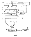
- Figure 1 is a schematic representation of an exemplary system for producing a polymer product from a base resin and colorant, including a color probe in accordance with an exemplary embodiment of the present invention.
- Figure 2 is a schematic representation of the color probe illustrated in Figure 1 in an exemplary embodiment.
- Figure 3 is a schematic representation of light transmission through, and reflection from, a sample for measuring color thereof using the color probe of Figure 2.
-
- Illustrated schematically in Figure 1 is a
polymer production system 10 in accordance with an exemplary embodiment of the present invention.System 10 includes aconventional blender 12 employing avessel 12a for receiving and blending a conventionalpolymer base resin 14 with one or moreconventional colorants 16. - A
conventional resin dispenser 18 is operatively joined toblender 12 for selectively addingresin 14 thereto. Aconventional colorant dispenser 20 is operatively joined toblender 12 for selectively addingcolorant 16 thereto. Blender 12 also includes a suitable paddle ormixer 12b for blending togetherbase resin 14 andcolorant 16, and any additional additives as desired. The resulting mixture batch orblend 22 after suitable blending is temporarily stored in aholding bin 24 operatively joined toblender 12. - Holding bin 24 is operatively pined to a conventional compounder or
extruder 26 which includes an extrusion screw that acts uponblend 22 delivered thereto to form, under heat, a polymerraw product 28 in any conventional form, such as pellets. - The
raw product 28 is in turn used by various manufacturers to produce final products in various forms and configurations having the inherent color thereof. The color of the raw product is important in many final products requiring specific colors. Repeatability of accurate final product color requires repeatability in color of the raw product itself. - The color of
raw product 28 may initially be manually adjusted by adjustingcolorant 16 in an interactive process until the color ofraw product 28 is within an acceptable range based on the reference plaque color. Sample plaques are formed as described above for measuring color thereof using conventional color sensors in the exemplary form of a spectrocolorimeter. Color measurement is usually made by reflecting light off the surface of the sample plaque and performing spectrum analysis thereof for determining color. -
System 10, illustrated in Figure 1, includes a color monitor orprobe 30 in optical communication withblender 12 for measuring internal color ofblend 22 itself, instead of measuring the color ofraw product 28. After the blender has operated for a sufficient time to thoroughly mixresin 14 withcolorant 16,blend 22 takes on a uniform color which is measurable byprobe 30. In the embodiment of Figure 1,blend 22 comprises a powder colored by the action ofcolorant 16. The powder is formed of individual small partides having irregular, three-dimensional surface contours.Probe 30, therefore, is optically joined toblender vessel 12a so as to cover the field of view of aprobe zone portion 42 ofblend 22 containing individual powder particles ofblend 22. By accurately measuring the color ofsamples 22a of the powder particles, the color ofblend 22 itself may be determined. - The measured color of
blend 22 is used for controlling operation ofsystem 10. To accomplish this,system 10 further includes asuitable controller 32 operatively coupled to both the resin andcolorant dispensers blend 22.Probe 30 is operatively coupled tocontroller 32 for varying the blend ratio of colorant to resin to control color of the blend in response to measured color of asample 22a of the blend powder particles. -
Controller 32 may take any conventional form such as a digitally programmable computer which compares a color signal fromprobe 30 to a reference signal for the desired color ofblend 22 required for achieving a corresponding desired color ofraw product 28.Controller 32 responds to deviation between the measured color ofblend 22 and the desired color thereof by varying appropriate control valves (not shown) inresin dispenser 18 orcolorant dispenser 20, or both, as required to control the color ofblend 22. A closed-loop feedback control system may be implemented in suitable software withincontroller 32 for controlling operation ofsystem 10 to achieve the desired color ofblend 22 andproduct 28. - A preferred embodiment of
color probe 30, as illustrated in Figure 2, includes ahousing 34 suitably pined toblender vessel 12a. Blender 12 includes a suitable opticallytransparent window 12c in the wall ofvessel 12a for permitting optical communication betweenprobe 30 andblender 12. Asuitable light source 36 is mounted inhousing 34 for emitting and projecting anincident light beam 38 towardprobe zone 42 insideblender 12.Light source 36 may be of any conventional form for use in measuring color ofsamples 22a, and, for example, may comprise a tungsten-halogen light source for producing broad spectrum white light. - A
color sensor 40 is suitably mounted inhousing 34 at an oblique angle withlight source 36 and directed towardprobe zone 42 containing blendpowder particle samples 22a.Samples 22a are comprised of a substantial number of randomly oriented blend powder particles.Color sensor 40 may comprise, for example, any instrument which is effective for performing spectrum color analysis of incident light thereon, such as those commonly referred to as a spectrometer, spectrocolorimeter, or spectrophotometric colorimeter. -
Light source 36 andcolor sensor 40 are optically aligned with afixed reference plane 42a withinprobe zone 42 to effect angles of incidence and reflection relative thereto, each having a magnitude substantially equal to the conventionally known Brewster's maximum polarization angle B for the specific refractive index (n) of aspecific sample 22a for measuring internal color thereof. As shown in Figure 2,probe zone 42 is defined by both the viewing angle ofcolor sensor 40 and the cooperating illumination angle oflight source 36 within which one ormore samples 22a are illuminated for color measurement bysensor 40.Light source 36 andcolor sensor 40 are simply mounted inhousing 34 in a fixed spatial orientation to effect Brewsters angle viewing ofsamples 22a. - Figure 3 is a schematic representation of
light beam 38 illuminating anexemplary sample 22a to explain the principle of operation ofcolor probe 30 in accordance with the present invention. Unpolarized light, such aslight beam 38, when incident upon a sample surface, produces a reflected ray orwave 38a (shown in phantom), and a refracted ray orwave 38b.Incident light beam 38 is directed to have an angle of incidence B relative to the normal toreference plane 42a, and reflectedwave 38a has an equal angle B of reflection relative thereto. -
Reflected wave 38a undergoes plane-polarization when light is incident at Brewster's angle, since at that angle light vibrating in the plane of incidence is not reflected but is refracted into the material. Brewsters law provides that the angle of incidence for maximum polarization depends on the refractive index (n) of the material affected. Correspondingly, Brewsters angle B equals the arctangent of the refractive index (n) ofsample 22a, which effects maximum polarization oflight beam 38. For ordinary glass, Brewster's angle is about 57°, whereas the specific composition ofsample 22a has its own specific Brewster's angle. - Accordingly,
light source 36 andcolor sensor 40 are preferably aligned relative to referenceplane 42a to direct each of the incident and reflected light beams at the specific Brewster's angle B for the refractive index ofsample 22a, such as the colored base resin ofblend 22. - In Figure 3, the unpolarized incident
light beam 38 is schematically represented by a series of dots and crosslines representing the two mutually perpendicular plane-polarized components thereof, specifically, a perpendicular polarization ray or wave vibrating perpendicular to the plane of incidence, and a parallel polarization ray or wave vibrating in the plane of incidence, respectively. - Of those waves vibrating in the plane of incidence, one part is usually reflected and the remaining part is refracted for all angles, with the single exception of the Brewster polarizing angle for which all of the light is refracted. Of the wave vibrating perpendicular to the plane of incidence, some of the energy is reflected and the rest refracted for any angle of incidence. Thus, the refracted
ray 38b usually contains some of both planes of polarization. - For a single surface of ordinary glass with a refractive index n=1.5, it has been shown that at the Brewster polarizing angle of 57°, 100 percent of the light vibrating parallel to the plane of incidence is transmitted, whereas for the perpendicular vibrations only 85 percent of the light is transmitted, the other 15 percent being reflected.
- Accordingly, using the Brewster phenomena,
light source 36 andcolor sensor 40 are specifically oriented to maximize the reception incolor sensor 40 ofrefraction wave 38b after its journey throughsample 22a, while minimizing the magnitude ofreflection wave 38a. In this way, the internal color ofsample 22a may be probed for obtaining a more accurate indication of the color ofsample 22a, as opposed to probing the color ofsample 22a from its surface only. - While Figure 3 illustrates only a
single sample 22a, in practice a large number ofsamples 22a will be withinprobe zone 42 in random orientations. Statistically, a suitable number of theindividual samples 22a will include areflection surface 22b aligned parallel withreference plane 42a for effecting Brewster angle viewing of thosesamples 22a. But for the Brewster angle alignment oflight source 36,color sensor 40, andreflection surfaces 22b,light beam 38 could reflect from those surfaces directly into color sensor 40 (Figure 2), which is undesirable. The Brewster angle condition minimizes collection of specular reflected light while maximizing collection of light initially refracted insidesamples 22a before reachingsensor 40. - Recognizing the polarization effected in the Brewster angle operating condition, additional polarization may be effected to further reduce or eliminate reflected
wave 38a. More specifically, in the embodiment illustrated in Figure 2, a first linear polarization filter orpolarizer 44 is optically aligned betweenlight source 36 andprobe zone 42 for selectivelypolarizing light beam 38 to prevent generation ofreflection wave 38a fromsample 22a, while permitting transmission ofrefraction wave 38b intosample 22a and, upon internal reflection therein, passing tosensor 40. - As can be seen in Figure 3,
unpolarized light beam 38 withoutpolarizer 44 would contain components polarized perpendicular to the plane of incidence or reflection according to Brewster's law, and would generatereflection wave 38a. However,reflection wave 38a may be prevented by usingfirst polarizer 44 specifically oriented therefor. In this condition,reflection wave 38a is illustrated in phantom indicating where it would exist but forpolarizer 44 which prevents its transmission to color sensor 40 (Figure 2). - The parallel polarization component of
light beam 38 is unaffected bypolarizer 44 and refracts insidesample 22a along the exemplary intemal reflection path shown forrefraction wave 38b. Statistically,many samples 22a will have internally reflected refraction waves 38b exiting the samples in the direction ofcolor sensor 40 for measuring the intemal color. -
Refraction wave 38b is illustrated in Figure 3 as reflecting internally off of multiple surfaces ofsample 22a. In the usual case, the normals to these planes will not all lie in the same plane. In consequence of this three-dimensional orientation, and also the general laws of reflection,refraction wave 38b will undergo different polarizations in its travel.Refraction wave 38b may also scatter off of inclusions insample 22a, further affecting its polarization. - Preferably, a second linear polarization filter or
polarizer 46 may be optically aligned betweenprobe zone 42 andcolor sensor 40 for transmittingrefraction wave 38b tosensor 40 while blocking differently polarized components thereof, as well as for blockingreflection wave 38a from reachingsensor 40 and blocking light that is multiply scattered to small angles, with polarization rotation, from reachingsensor 40. - By choosing, the directions of illumination, observation, and polarization in accordance with Brewster's law, there is minimal direct surface reflection or scattering from
samples 22a into the viewed direction monitored bycolor sensor 40. In this way, little or none of the light striking sample surfaces at Brewsters angle, with polarization, is reflected, but instead, most or all of the available light passes into the interior ofsamples 22a as refraction waves 38b where they can probe bulk color, with higher contrast and accuracy than conventional surface measuring color sensors. - The embodiment illustrated in Figure 2 preferably includes a
first collimating lens 48 optically aligned betweenlight source 36 andfirst polarizer 44 for collimatinglight beam 38 towardprobe zone 42. Correspondingly, asecond lens 50 is optically aligned betweensecond polarizer 46 andcolor sensor 40 for focusing collected light therefrom uponsensor 40.Sensor 40 preferably includes a pinhole or small slit inlet 52 sized to define a suitably narrow view direction corresponding to the volume ofprobe zone 42 to maintain viewing within narrow bounds of the Brewster angle B. Alternatively, an optical fiber might serve this purpose as well. In this way,probe zone 42 is illuminated with collimated light to maximize internal refraction withinsamples 22a while minimizing surface reflections therefrom, with refraction waves38b leaving samples 22a and being statistically observed by use of directionally-orientedcolor sensor 40. -
Color probe 30 thus allows highly accurate measurement of powder color by controlling the illumination and observation directions and polarizations so that direct reflections from the individual powder particles are minimized, allowing clearer detection of the interior color of the powder. The ability to measure the color ofpowder blend 22 inblender 12 and to make adjustments to the color for obtaining a desired final color for the extruded product 28 (Figure 1) has many benefits. For example, the need to take a powder sample, run it through an off-line extruder, and form sample plaques in order to obtain a preliminary color measurement, will be eliminated, eliminating the need to maintain off-line equipment for this purpose and reducing the labor necessary to achieve an on-color blend. Furthermore, less material will be wasted or recycled because the number of off-color blends can be reduced. Extruder down-time while off-color blends are adjusted and brought into specification can also be reduced. - Although the blend color is not necessarily the same as the color of the produced raw product, there is a necessary correlation therebetween which allows the measurement of the blend color to determine the color of the extruded
product 28. - These and other advantages of the invention are provided by the ability to measure interior color of
samples 22a at the beginning of the manufacturing process when the raw materials are initially blended. Although the invention has been described with respect to this particular application, it may find utility in any application requiring accurate measurement of interior color of samples by refracting light therethrough. For example,light source 36 and color sensor 40 (Figure 2) may be used with suitable optical transmission fibers for carrying the light to and fromsamples 22a. In this way either or both of thelight source 36 andcolor sensor 40 may be remotely located using the Brewster angle configuration.
Claims (10)
- A probe (30) for measuring color in a sample (22a) having a refractive index, comprising:a light source (36) for emitting a light beam (38) toward said sample (22a); anda color sensor (40) disposed obliquely with said light source (36) toward a common probe zone (42) for receiving said sample (22a) therein, with said light source (36) and sensor (40) being optically aligned with a reference plane (42a) in said zone (42) to effect angles of incidence and reflection relative thereto having a magnitude substantially equal to Brewster's maximum polarization angle for said refractive index of said sample (22a) for measuring internal color thereof.
- A probe according to claim 1 further comprising a first polarizer (44) optically aligned between said light source (36) and probe zone (42) for polarizing said light beam (38) to prevent a reflection wave (38a) thereof from said sample from reaching said sensor (40), while permitting transmission of a refraction wave (38b) thereof into said sample (22a).
- A probe according to claim 2 wherein said first polarizer (44) is a linear polarizer.
- A probe according to claim 3 further comprising a first lens (48) for collimating said light beam toward said probe zone (42).
- A probe according to claim 4 further comprising a second polarizer (46) optically aligned between said probe zone (42) and said sensor (40) for transmitting said refraction wave (38b) to said sensor 40, while blocking transmission of differently polarized light.
- A probe according to claim 5 further comprising a second lens (50) optically aligned between said second polarizer (46) and said sensor (40) for focusing collected light therefrom into said sensor (40).
- A probe according to claim 6 in combination with: a blender (12) for blending a base resin (14) with a colorant (16) to form a blend (22);a) resin dispenser (18) for adding said resin (14) in said blender (12); a colorant dispenser (20) for adding said colorant (16) in said blender (12); anda controller (32) operatively joined to said resin and colorant dispensers (18, 20) for controlling ratio of said colorant and resin in said blend; and whereinsaid color probe (30) is optically joined to said blender (12) to position said probe zone (42) therein for randomly receiving a portion of said blend (22) to define said sample (22a); andsaid color probe (30) is operatively joined to said controller (32) for varying said blend ratio to control color thereof in response to measured color of said sample (22a).
- A method for measuring color in a sample (22) having a probe zone therein and having a refractive index, comprising:projecting a light beam toward a reference plane within the probe zone of said sample (22a) at an angle of incidence to substantially effect Brewster's maximum polarization angle for the specific refreactive index of said sample; andmeasuring color of said sample (22a) at about Brewster's maximum polarization angle relative to a normal to said reference plane for a light wave refracted inside said sample (22a) from said light beam.
- A method according to claim 8 further comprising polarizing said light beam (38) to prevent from said color measurement a reflection wave (38a) thereof from said sample, while permitting transmission of a refraction wave (38b) thereof into said sample (22a).
- A method according to claim 9 further comprising: blending a base resin 14 with a colorant (16) to form a blend (22); controlling ratio of said colorant and resin in said blend; measuring color of a portion of said blend as said sample; and varying said blend ratio to control blend color in response to said measured color of said sample (22a)
Applications Claiming Priority (2)
| Application Number | Priority Date | Filing Date | Title |
|---|---|---|---|
| US915288 | 1997-08-20 | ||
| US08/915,288 US5963332A (en) | 1997-08-20 | 1997-08-20 | Internal color probe |
Publications (2)
| Publication Number | Publication Date |
|---|---|
| EP0899549A2 true EP0899549A2 (en) | 1999-03-03 |
| EP0899549A3 EP0899549A3 (en) | 2000-03-29 |
Family
ID=25435514
Family Applications (1)
| Application Number | Title | Priority Date | Filing Date |
|---|---|---|---|
| EP98306650A Ceased EP0899549A3 (en) | 1997-08-20 | 1998-08-19 | Internal color probe |
Country Status (4)
| Country | Link |
|---|---|
| US (1) | US5963332A (en) |
| EP (1) | EP0899549A3 (en) |
| JP (1) | JPH11132851A (en) |
| SG (1) | SG67535A1 (en) |
Cited By (1)
| Publication number | Priority date | Publication date | Assignee | Title |
|---|---|---|---|---|
| WO2007067587A1 (en) * | 2005-12-05 | 2007-06-14 | E. I. Du Pont De Nemours And Company | Probe apparatus for measuring a color property of a liquid |
Families Citing this family (52)
| Publication number | Priority date | Publication date | Assignee | Title |
|---|---|---|---|---|
| US6373573B1 (en) | 2000-03-13 | 2002-04-16 | Lj Laboratories L.L.C. | Apparatus for measuring optical characteristics of a substrate and pigments applied thereto |
| US6254385B1 (en) | 1997-01-02 | 2001-07-03 | Lj Laboratories, Llc | Apparatus and method for measuring optical characteristics of teeth |
| US6307629B1 (en) * | 1997-08-12 | 2001-10-23 | Lj Laboratories, L.L.C. | Apparatus and method for measuring optical characteristics of an object |
| US6301004B1 (en) | 2000-05-31 | 2001-10-09 | Lj Laboratories, L.L.C. | Apparatus and method for measuring optical characteristics of an object |
| US6501542B2 (en) | 1998-06-30 | 2002-12-31 | Lj Laboratories, Llc | Apparatus and method for measuring optical characteristics of an object |
| US6573984B2 (en) | 1998-06-30 | 2003-06-03 | Lj Laboratories Llc | Apparatus and method for measuring optical characteristics of teeth |
| US6249348B1 (en) * | 1998-11-23 | 2001-06-19 | Lj Laboratories, L.L.C. | Integrated spectrometer assembly and methods |
| IT1316145B1 (en) * | 2000-10-26 | 2003-03-28 | Viptronic Srl | PHOTOELECTRIC MEASUREMENT DEVICE EQUIPPED WITH A DIPOLARIZATION FILTER. |
| US6903813B2 (en) | 2002-02-21 | 2005-06-07 | Jjl Technologies Llc | Miniaturized system and method for measuring optical characteristics |
| JP2007010576A (en) * | 2005-07-01 | 2007-01-18 | Toyota Motor Corp | Colorimetric device and colorimetric method |
| DE102005041455A1 (en) * | 2005-08-31 | 2007-03-15 | Abb Patent Gmbh | Automated device e.g. field device and control device, has first program assigned to microcontroller for conversion of data bit stream and second program assigned to microcontroller for recognition of frequency-modulated line signal |
| DE102005043482A1 (en) * | 2005-09-13 | 2007-03-15 | Abb Patent Gmbh | Automation technology device for communication among of spatially distributed functional units, has ladder network with monoflop, scanning device, low-pass filter and comparator, for reconstruction of received data |
| DE102005043481A1 (en) * | 2005-09-13 | 2007-03-15 | Abb Patent Gmbh | Automation technical device e.g. protocol converter, for use as component of higher-level device, has counter and microcontroller, where program execution of microcontroller is interrupted by interrupt request for handling counter |
| DE102005043485A1 (en) * | 2005-09-13 | 2007-03-15 | Abb Patent Gmbh | Automation technical equipment has several spatial distributed functional units whereby they communicate with each other by means of common transmission protocol |
| DE102005043487A1 (en) * | 2005-09-13 | 2007-03-15 | Abb Patent Gmbh | Automating technical device for e.g. controlling engineering, has microcontroller attached to memory, where sequential result of sampling values of time response is stored in memory such that values are outputted with clocks of timers |
| US7719686B2 (en) * | 2005-12-05 | 2010-05-18 | E.I. Du Pont De Nemours And Company | System for measuring a color property of a liquid |
| US7477394B2 (en) * | 2005-12-05 | 2009-01-13 | E.I Du Pont De Nemours & Company | Method for measuring a color property of a liquid using a liquid measurement cell having a transparent partition therein |
| US7423755B2 (en) * | 2005-12-05 | 2008-09-09 | E.I. Du Pont De Nemours And Company | Liquid measurement cell having a transparent partition therein |
| US7542143B2 (en) * | 2005-12-05 | 2009-06-02 | E.I. Du Pont De Nemours And Company | Liquid measurement cell having a pressurized air cavity therein |
| BR112012030576A2 (en) * | 2010-06-03 | 2017-06-27 | Koninl Philips Electronics Nv | tissue analyte measuring apparatus and method for measuring a patient's tissue analyte |
| JP2014010093A (en) * | 2012-07-02 | 2014-01-20 | Seiko Epson Corp | Spectral image pickup device |
| US9542016B2 (en) | 2012-09-13 | 2017-01-10 | Apple Inc. | Optical sensing mechanisms for input devices |
| US9086738B2 (en) * | 2013-03-12 | 2015-07-21 | Apple Inc. | Multi-surface optical tracking system |
| US9753436B2 (en) | 2013-06-11 | 2017-09-05 | Apple Inc. | Rotary input mechanism for an electronic device |
| US9627163B2 (en) | 2013-08-09 | 2017-04-18 | Apple Inc. | Tactile switch for an electronic device |
| WO2015122885A1 (en) | 2014-02-12 | 2015-08-20 | Bodhi Technology Ventures Llc | Rejection of false turns of rotary inputs for electronic devices |
| US10190891B1 (en) | 2014-07-16 | 2019-01-29 | Apple Inc. | Optical encoder for detecting rotational and axial movement |
| US9797752B1 (en) | 2014-07-16 | 2017-10-24 | Apple Inc. | Optical encoder with axially aligned sensor |
| US10066970B2 (en) | 2014-08-27 | 2018-09-04 | Apple Inc. | Dynamic range control for optical encoders |
| US9797753B1 (en) | 2014-08-27 | 2017-10-24 | Apple Inc. | Spatial phase estimation for optical encoders |
| DE212015000214U1 (en) | 2014-09-02 | 2017-05-12 | Apple Inc. | Wearable electronic device |
| JP6515185B2 (en) | 2015-03-05 | 2019-05-15 | アップル インコーポレイテッドApple Inc. | Watch, wrist-worn electronic device and wearable electronic device having an optical encoder having direction dependent optical characteristics |
| JP6479997B2 (en) | 2015-03-08 | 2019-03-06 | アップル インコーポレイテッドApple Inc. | Compressible seal for rotatable and translatable input mechanism |
| US9952682B2 (en) | 2015-04-15 | 2018-04-24 | Apple Inc. | Depressible keys with decoupled electrical and mechanical functionality |
| US10018966B2 (en) | 2015-04-24 | 2018-07-10 | Apple Inc. | Cover member for an input mechanism of an electronic device |
| EP3467475B1 (en) | 2015-12-22 | 2020-04-22 | X-Rite Switzerland GmbH | Sparkle measurement |
| US9891651B2 (en) | 2016-02-27 | 2018-02-13 | Apple Inc. | Rotatable input mechanism having adjustable output |
| US10551798B1 (en) | 2016-05-17 | 2020-02-04 | Apple Inc. | Rotatable crown for an electronic device |
| US10061399B2 (en) | 2016-07-15 | 2018-08-28 | Apple Inc. | Capacitive gap sensor ring for an input device |
| US10019097B2 (en) | 2016-07-25 | 2018-07-10 | Apple Inc. | Force-detecting input structure |
| US10664074B2 (en) | 2017-06-19 | 2020-05-26 | Apple Inc. | Contact-sensitive crown for an electronic watch |
| US10962935B1 (en) | 2017-07-18 | 2021-03-30 | Apple Inc. | Tri-axis force sensor |
| US11360440B2 (en) | 2018-06-25 | 2022-06-14 | Apple Inc. | Crown for an electronic watch |
| US11561515B2 (en) | 2018-08-02 | 2023-01-24 | Apple Inc. | Crown for an electronic watch |
| CN209560398U (en) | 2018-08-24 | 2019-10-29 | 苹果公司 | Electronic watch |
| US11181863B2 (en) | 2018-08-24 | 2021-11-23 | Apple Inc. | Conductive cap for watch crown |
| US11194298B2 (en) | 2018-08-30 | 2021-12-07 | Apple Inc. | Crown assembly for an electronic watch |
| CN209625187U (en) | 2018-08-30 | 2019-11-12 | 苹果公司 | Electronic watch and electronic equipment |
| DE102019201440A1 (en) * | 2019-02-05 | 2020-08-06 | Implen GmbH | Device for light spectroscopic analysis |
| US11194299B1 (en) | 2019-02-12 | 2021-12-07 | Apple Inc. | Variable frictional feedback device for a digital crown of an electronic watch |
| US11550268B2 (en) | 2020-06-02 | 2023-01-10 | Apple Inc. | Switch module for electronic crown assembly |
| US11269376B2 (en) | 2020-06-11 | 2022-03-08 | Apple Inc. | Electronic device |
Citations (3)
| Publication number | Priority date | Publication date | Assignee | Title |
|---|---|---|---|---|
| US4398541A (en) * | 1978-05-25 | 1983-08-16 | Xienta, Inc. | Method and apparatus for measuring moisture content of skin |
| EP0304805A2 (en) * | 1987-08-24 | 1989-03-01 | Erwin Sick GmbH Optik-Elektronik | Optical scanning apparatus for a transparent web of material |
| US5559173A (en) * | 1993-10-04 | 1996-09-24 | General Electric Company | System for controlling the color of compounded polymer(s) using in-process color measurements |
Family Cites Families (2)
| Publication number | Priority date | Publication date | Assignee | Title |
|---|---|---|---|---|
| DE3271878D1 (en) * | 1982-04-10 | 1986-08-07 | Hell Rudolf Dr Ing Gmbh | Method and device for measuring the density of colour coatings of a still wet printing dye |
| US4878756A (en) * | 1988-08-08 | 1989-11-07 | Honeywell Inc. | Method and apparatus for sensing color |
-
1997
- 1997-08-20 US US08/915,288 patent/US5963332A/en not_active Expired - Fee Related
-
1998
- 1998-08-11 JP JP10226392A patent/JPH11132851A/en active Pending
- 1998-08-12 SG SG1998002983A patent/SG67535A1/en unknown
- 1998-08-19 EP EP98306650A patent/EP0899549A3/en not_active Ceased
Patent Citations (3)
| Publication number | Priority date | Publication date | Assignee | Title |
|---|---|---|---|---|
| US4398541A (en) * | 1978-05-25 | 1983-08-16 | Xienta, Inc. | Method and apparatus for measuring moisture content of skin |
| EP0304805A2 (en) * | 1987-08-24 | 1989-03-01 | Erwin Sick GmbH Optik-Elektronik | Optical scanning apparatus for a transparent web of material |
| US5559173A (en) * | 1993-10-04 | 1996-09-24 | General Electric Company | System for controlling the color of compounded polymer(s) using in-process color measurements |
Non-Patent Citations (1)
| Title |
|---|
| LEUNG F Y C ET AL: "COLOUR RECOGNITION BY FIBRE-OPTIC SENSING" INTERNATIONAL JOURNAL OF OPTOELECTRONICS (INCL.OPTICAL COMPUTING & PROCESSING),GB,TAYLOR & FRANCIS, LONDON, vol. 9, no. 5, 1 September 1994 (1994-09-01), pages 367-378, XP000510034 ISSN: 0952-5432 * |
Cited By (1)
| Publication number | Priority date | Publication date | Assignee | Title |
|---|---|---|---|---|
| WO2007067587A1 (en) * | 2005-12-05 | 2007-06-14 | E. I. Du Pont De Nemours And Company | Probe apparatus for measuring a color property of a liquid |
Also Published As
| Publication number | Publication date |
|---|---|
| SG67535A1 (en) | 1999-09-21 |
| JPH11132851A (en) | 1999-05-21 |
| US5963332A (en) | 1999-10-05 |
| EP0899549A3 (en) | 2000-03-29 |
Similar Documents
| Publication | Publication Date | Title |
|---|---|---|
| US5963332A (en) | Internal color probe | |
| CA1136886A (en) | Spectrophotometer | |
| EP0901004B1 (en) | Sensing blend color homogeneity | |
| US10703018B2 (en) | Spectral properties-based system and method for feeding masterbatches into a plastic processing machine | |
| CN1100002A (en) | Apparatus for mixing and detecting on-line homogeneity | |
| KR101133379B1 (en) | High-accuracy flow-oriented multi angle reflectance sensor | |
| KR20190045340A (en) | A sensor for measuring the permeation and / or forward scattering and / or re-emission substantially simultaneously and for simultaneously measuring the permeation and forward scattering or transmission and re-emission of the liquid sample | |
| EP1082600B1 (en) | Calibration verification system for turbidimeter | |
| Garton et al. | Molecular orientation measurements in polymers by infrared spectral subtraction | |
| Kent-Jones et al. | A photo-electric method of determining the colour of flour as affected by grade, by measurements of reflecting power | |
| GB2496897A (en) | Measurement of colour strength of a diffusely reflective liquid e.g. paint | |
| US6075608A (en) | Blend segregation detection | |
| JP4033563B2 (en) | Toning method of transparent resin molding | |
| CN209027991U (en) | A kind of water turbidity detection device based on scattering transmittance | |
| CN106198399B (en) | Definition measuring device | |
| CN114868008A (en) | Method for evaluating orientation of nanowires in transparent material, process control method using the evaluation method, and method for producing cured resin | |
| KR200150091Y1 (en) | Sample attaching unit | |
| Janostik et al. | Effect of pigment concentration on mechanical properties and on color stability of polycarbonate | |
| Janoštík et al. | Effect of Pigment Concentration on Mechanical Properties and on color stability of Polycarbonate | |
| EP2032968B1 (en) | Diffuse reflection probe for optical measurements | |
| Brown | Optical properties | |
| JPS6140540B2 (en) | ||
| SU1728735A1 (en) | Method of light reflective sample manufacturing | |
| Foulk | Final Technical Report-Advanced Optical Sensors to Minimize Energy Consumption in Polymer Extrusion Processes | |
| Kehlenbeck et al. | In-line determination of the mixing quality by Near Infrared Spectroscopy |
Legal Events
| Date | Code | Title | Description |
|---|---|---|---|
| PUAI | Public reference made under article 153(3) epc to a published international application that has entered the european phase |
Free format text: ORIGINAL CODE: 0009012 |
|
| AK | Designated contracting states |
Kind code of ref document: A2 Designated state(s): DE ES FR GB IT NL |
|
| AX | Request for extension of the european patent |
Free format text: AL;LT;LV;MK;RO;SI |
|
| PUAL | Search report despatched |
Free format text: ORIGINAL CODE: 0009013 |
|
| AK | Designated contracting states |
Kind code of ref document: A3 Designated state(s): AT BE CH CY DE DK ES FI FR GB GR IE IT LI LU MC NL PT SE |
|
| AX | Request for extension of the european patent |
Free format text: AL;LT;LV;MK;RO;SI |
|
| RIC1 | Information provided on ipc code assigned before grant |
Free format text: 7G 01J 3/46 A, 7G 01N 21/25 B |
|
| 17P | Request for examination filed |
Effective date: 20000929 |
|
| AKX | Designation fees paid |
Free format text: DE ES FR GB IT NL |
|
| 17Q | First examination report despatched |
Effective date: 20031027 |
|
| STAA | Information on the status of an ep patent application or granted ep patent |
Free format text: STATUS: THE APPLICATION HAS BEEN REFUSED |
|
| 18R | Application refused |
Effective date: 20050602 |