EP0899111A2 - Ink cartridge insertion mechanism for an ink jet printer - Google Patents
Ink cartridge insertion mechanism for an ink jet printer Download PDFInfo
- Publication number
- EP0899111A2 EP0899111A2 EP98115975A EP98115975A EP0899111A2 EP 0899111 A2 EP0899111 A2 EP 0899111A2 EP 98115975 A EP98115975 A EP 98115975A EP 98115975 A EP98115975 A EP 98115975A EP 0899111 A2 EP0899111 A2 EP 0899111A2
- Authority
- EP
- European Patent Office
- Prior art keywords
- ink
- cartridge
- supply needle
- needle
- ink cartridge
- Prior art date
- Legal status (The legal status is an assumption and is not a legal conclusion. Google has not performed a legal analysis and makes no representation as to the accuracy of the status listed.)
- Granted
Links
Images


Classifications
-
- B—PERFORMING OPERATIONS; TRANSPORTING
- B41—PRINTING; LINING MACHINES; TYPEWRITERS; STAMPS
- B41J—TYPEWRITERS; SELECTIVE PRINTING MECHANISMS, i.e. MECHANISMS PRINTING OTHERWISE THAN FROM A FORME; CORRECTION OF TYPOGRAPHICAL ERRORS
- B41J2/00—Typewriters or selective printing mechanisms characterised by the printing or marking process for which they are designed
- B41J2/005—Typewriters or selective printing mechanisms characterised by the printing or marking process for which they are designed characterised by bringing liquid or particles selectively into contact with a printing material
- B41J2/01—Ink jet
- B41J2/17—Ink jet characterised by ink handling
- B41J2/175—Ink supply systems ; Circuit parts therefor
- B41J2/17503—Ink cartridges
- B41J2/1752—Mounting within the printer
- B41J2/17523—Ink connection
-
- B—PERFORMING OPERATIONS; TRANSPORTING
- B41—PRINTING; LINING MACHINES; TYPEWRITERS; STAMPS
- B41J—TYPEWRITERS; SELECTIVE PRINTING MECHANISMS, i.e. MECHANISMS PRINTING OTHERWISE THAN FROM A FORME; CORRECTION OF TYPOGRAPHICAL ERRORS
- B41J2/00—Typewriters or selective printing mechanisms characterised by the printing or marking process for which they are designed
- B41J2/005—Typewriters or selective printing mechanisms characterised by the printing or marking process for which they are designed characterised by bringing liquid or particles selectively into contact with a printing material
- B41J2/01—Ink jet
- B41J2/17—Ink jet characterised by ink handling
- B41J2/175—Ink supply systems ; Circuit parts therefor
- B41J2/17503—Ink cartridges
- B41J2/1752—Mounting within the printer
Definitions
- the present invention relates to an ink jet printer in which an ink cartridge is used as an ink reservoir from which ink is supplied for printing, and relates particularly to a mechanism for inserting an ink cartridge into such an ink jet printer.
- ink cartridge insertion mechanism One common mechanism for inserting an ink cartridge to an ink jet printer (referred to as “ink cartridge insertion mechanism” below) requires sliding the ink cartridge into position on a cartridge holder of the ink jet printer such that an ink outlet piece in the ink cartridge is pierced by an ink supply needle disposed in the cartridge holder.
- the ink cartridge described in this document comprises a flexible ink bag filled with ink, an ink outlet piece formed in the ink bag, and a rectangular, rigid plastic case for holding the ink bag.
- the ink outlet piece of the ink bag is exposed at the front end face of the plastic case.
- the ink cartridge is thus slid horizontally into the cartridge holder so that the ink supply needle in the cartridge holder is inserted into the ink outlet piece.
- the ink supply needle is exposed in the opening of the cartridge holder through which the ink cartridge is inserted.
- JP-A-5-16378/1993 teaches an ink cartridge insertion mechanism having a shutter disposed on the cartridge holder. This shutter opens when an ink cartridge is inserted into the opening, and closes again when the ink cartridge is removed such that when no ink cartridge is installed the shutter shields and protects the ink supply needle.
- US-A-5,186,291 discloses an ink cartridge insertion mechanism of an ink jet printer employing a protection plate rotatably supported between first and second positions. In its first position the protection plate is in front of the tip of the ink supply needle. In its second position the protection plate is rotated toward the needle and the needle is exposed through a hole in the protection plate so as to be able to enter an ink cartridge. The protection plate is automatically moved from its first to its second position in conjunction with the inserting movement of the ink cartridge.
- Ink jet printers are normally tested after they have been assembled in the factory and before shipment. In printers of the above mentioned kind this requires that an ink cartridge has to be actually loaded and the ink supply needle on the holder has to be inserted into the ink outlet piece of the cartridge. When the test is completed, the ink cartridge is removed and printers that have passed the test are then shipped. It will be obvious that this test method leaves an amount of ink in the ink supply path after the test. There is thus the possibility that this residual ink will leak from the tip of the ink supply needle during shipping. Such leakage can soil the area around the needle, and this soiling can lead to customer complaints.
- An ink cartridge insertion mechanism has movable ink absorption device for absorbing ink leaking from the ink supply needle.
- the type of ink jet printer in which such ink cartridge insertion mechanism is typically used commonly has a cartridge receiver to which an ink cartridge is installed by inserting the ink cartridge in the axial direction of the ink supply needle so that the ink supply needle is inserted into an ink outlet piece in the ink cartridge.
- the ink absorption means is normally held in a first or ink absorption position when no ink cartridge is installed. When an ink cartridge is inserted and installed, the ink absorption means moves in conjunction with insertion operation to a second or retracted position at which it does not interfere with the ink cartridge insertion.
- the ink absorption means is positioned to absorb any ink that might leak from the ink supply needle whenever no ink cartridge is installed in the printer. Ink leaking from the ink supply needle is thus collected by the ink absorption means, and the area around the ink supply needle will not be soiled by leaking ink.
- the ink absorption means is moved in conjunction with ink cartridge insertion to the retracted position where it does not interfere with ink cartridge insertion. Providing such ink absorption means therefore does not create any inconvenience or problem with inserting and installing an ink cartridge.
- the ink absorption means of the present invention is preferably also used as a means for protecting the ink supply needle so that the ink supply needle cannot be directly touched or damaged when no ink cartridge is installed.
- the ink absorption means preferably comprises an ink absorption material and a pivot plate for supporting the ink absorption material.
- the pivot plate is pivotally mounted in the cartridge receiver so that it can pivot between the ink absorption position and the retracted position.
- a spring is preferably provided for applying a resilient force to the pivot plate as a means of constantly urging the pivot plate to and holding it in the ink absorption position.
- the pivot plate preferably has a slit through which the ink supply needle can pass when the pivot plate moves to the ink absorption position, and the ink absorption material is attached to a back side of the pivot plate.
- the ink absorption material has a recessed channel at a position corresponding to said slit for accepting the ink supply needle that passed through said slit.
- the ink supply needle is effectively protected from the outside by the pivot plate and the ink absorption material when it is received in the recessed channel in the ink absorption material.
- the ink absorption material can both absorb any ink that might leak from the tip of the ink supply needle, and protect the ink supply needle, when no ink cartridge is installed.
- the pivot plate preferably comprises at a leading edge thereof an engaging part via which the pivot plate is pushed toward the retracted position by an ink cartridge when the ink cartridge is being inserted.
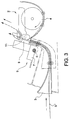
- Fig. 1 and Fig. 2 are oblique views from the front and back, respectively, of an ink jet printer comprising an ink cartridge insertion mechanism according to the present invention.
- Fig. 3 is a side sectional view showing the major elements of the paper transport path in the ink jet printer shown in Figs. 1 and 2.
- the transportation path of ink jet printer 1 conducts the print medium from either a roll paper loading mechanism 2 or a paper supply opening 3 to a printing region 11 (indicated by a dot-dash line in Fig. 1).
- Roll paper 4 is supplied from the roll paper loading mechanism 2, and cut sheet paper (such as A4 size or other size) or slip form 5 is inserted into the paper supply opening 3.
- An ink jet head 8 is held on a carriage mechanism 9 in a position opposing roll paper 4 or slip form 5 as it passes the printing region 11.
- the carriage mechanism 9 comprises a guide shaft 6, a carriage 7, and a motor (not shown in the figures) for driving the carriage 7.
- the carriage 7 is held in a manner enabling a reciprocating movement along the guide shaft 6 in a direction orthogonal to the direction in which roll paper 4 and slip form 5 are transported.
- the carriage 7 can thus move in two opposite directions (referred to as widthwise directions hereinafter) through an area containing the printing region 11.
- a capping face 11C of a capping mechanism 11B is disposed at one lateral side of the printing region 11.
- the capping mechanism 11B is located at the position to which the ink jet head 8 is retracted when the printer is in a standby mode between printing operations and where the nozzles of the ink jet head 8 are effectively covered by the capping face 11C, thereby preventing the ink in the nozzles from drying.
- Ink is supplied to the ink jet head 8 through an ink tube (not shown in the figures) from an ink supply unit 10, which is located beside the roll paper loading mechanism 2.
- the ink supply unit 10 has a cartridge loader (receiver) 30 for loading and holding a replaceable ink cartridge 20.
- FIG. 4 (A) An outline of an ink supply path for supplying ink to the ink jet head 8 is shown in Fig. 4 (A).
- An ink supply needle 31 and a waste ink needle 35 are provided in the cartridge loader 30 of the ink supply unit 10.
- the ink cartridge 20 is installed so that the ink supply needle 31 and the waste ink needle 35 are inserted completely to the ink cartridge 20.
- Ink is supplied from the ink cartridge 20 to the ink supply needle 31, passes through an ink tube 32, and is delivered to the ink jet head 8.
- the ink jet head 8 is then driven to eject ink drops from ink nozzles (not shown in the figures) of the ink jet head 8 onto the surface of the printing paper or other print medium transported to the printing position 11.
- an ink pump 33 is driven to suck ink from the nozzles for recovering the nozzles.
- the waste ink is collected through a waste ink tube 34 and the waste ink needle 35 in a waste ink collection unit 25 (shown in Fig. 4 (B)) inside the ink cartridge 20.
- FIG. 4 A schematic view of the internal structure of a typical ink cartridge 20 is shown in Fig. 4 (B).
- the ink cartridge 20 comprises a flexible ink bag 21 in which ink is sealed; a rigid case 23 inside of which is held the ink bag 21; and a waste ink collection unit 25 made from an ink absorbent material.
- An ink outlet piece 22 is formed in the ink bag 21.
- the rigid case 23 comprises a case body 23a and a case cover 23b.
- Two needle insertion holes 23d and 23f, and an ink cartridge positioning hole 23e, are provided in the front face 23c of the ink cartridge 20 as seen in Fig. 4 (B).
- One needle insertion hole 23d is for inserting the ink supply needle 31 into the ink outlet piece 22 from outside the ink cartridge 20.
- the other needle insertion hole 23f is for inserting the waste ink needle 35 into an opening or an inlet piece(not shown in the figure) of the waste ink collection unit 25 from outside the ink cartridge 20.
- a detection plate 24 for detecting how much ink remains is attached to a side of the ink bag 21.
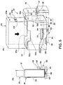
- Fig. 5 (A) and (B) show the ink supply unit 10 in a state before an ink cartridge 20 is installed.
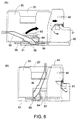
- Fig. 6 (A) and (B) show the ink supply unit 10 in a state before and after an ink cartridge 20 is slid to the ink supply needle 31 and the waste ink needle 35 using a sliding mechanism 60.
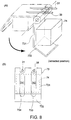
- An ink absorption and needle protection device 70 is shown in Fig. 7.
- the ink supply unit 10 comprises cartridge loader 30 for holding a replaceable ink cartridge 20.
- the ink supply needle 31 and the waste ink needle 35 are positioned horizontally as shown in the figure at the same height in the cartridge loader 30, and are enclosed in a hood 40 that is open on the open end side of the ink supply needle 31 and the waste ink needle 35.
- the device 70 is also contained within the hood 40.
- the device 70 protects the ink supply needle 31 and the waste ink needle 35, and absorbs any ink that may leak from the needles when no ink cartridge is installed.
- the cartridge loader 30 comprises a box-like cartridge holder 50 and a sliding mechanism 60.
- the cartridge holder 50 is disposed so that it can slide horizontally relative to the hood 40, that is, in the axial direction of needles 31 and 35.
- the sliding mechanism 60 is used to slide the cartridge holder 50 horizontally.
- This box-like cartridge holder 50 is described first below. On its top the cartridge holder 50 has an opening 51 enabling an ink cartridge 20 to be loaded from above into the cartridge holder 50. As a result, the ink cartridge 20 is inserted into the cartridge holder 50 from a direction substantially perpendicular to the axis of the ink supply needle 31.
- An opening 52d is provided in the front face 52 of the cartridge holder 50 at a position corresponding to the needle insertion holes 23d and 23f in the front face 23c of an inserted ink cartridge 20.
- a positioning hole 52e likewise corresponding to the positioning hole 23e of the ink cartridge 20 is also provided.
- the sliding mechanism 60 has a guide frame 61 on which the cartridge holder 50 is supported for sliding in two opposite directions.
- a guide rail 56 formed along the bottom of the cartridge holder 50 fits into and slides inside a rail channel 62 formed in the guide frame 61.
- a rack 63 is formed facing downward as shown in Fig. 5 on the side of the cartridge holder 50.
- a pinion 64 engaging the rack 63 is formed on the side of the guide frame 61 in a manner enabling the pinion 64 to pivot freely.
- An operating lever 65 is formed on one side of the pinion 64 extending substantially radially from the rotational axis 66 of the pinion 64.
- the device 70 is described next referring primarily to Fig. 7 and Fig. 8.
- the device 70 comprises a pivot plate 73, ink absorption material 74, and a pair of torsion springs 75 and 76.
- the pivot plate 73 is disposed so that it can pivot freely on support pins 71 and 72 relative to the side walls of the hood 40.
- the ink absorption material 74 is a rectangular body affixed to the back (bottom) of the pivot plate 73 as seen in the figures.
- the springs 75 and 76 apply a resilient force to the pivot plate 73, and thus constantly urge the pivot plate 73 to assume a particular position.
- the pivot plate 73 is made from a rigid material such as a metal plate or a hard plastic molding.
- the pivot plate 73 comprises a first part 731 and a second part 732.
- the first part 731 is substantially horizontal (and will be referred to as the horizontal part hereinafter) when no ink cartridge is installed.
- the second part 732 (referred to as the inclined part hereinafter) extends at a downward slope toward the opening of the hood 40 from the outside edge of the horizontal part 731.
- Support pin sockets 735 and 736 are formed at the inside end (opposite to the outside edge) of the pivot plate 73 on opposite locations on the lateral sides of the horizontal part 731.
- the support pins 71 and 72 fit in the support pin sockets 735 and 736, and the pivot plate 73 is thus supported in a manner enabling it to pivot freely.
- Slits 733 and 734 are formed in the horizontal part 731 of the pivot plate 73 at positions corresponding to the ink supply needle 31 and the waste ink needle 35, respectively, and are each sufficiently wider than the outside diameter of the corresponding needle.
- Recessed channels 741 and 742 with a substantially semicircular cross section are formed in the top of the ink absorption material 74 at positions corresponding to the slits 733 and 734.
- the width and depth of these recessed channels 741 and 742 are also sufficiently greater than the outside diameter of the corresponding one of needles 31 and 35.
- the channel width and the slit width are the same, but this is not essential to the invention.
- the pivot plate 73 is supported such that the horizontal part 731 is urged to a normally horizontal position by the pair of torsion springs 75 and 76. More specifically, the pivot plate 73 is supported such that the horizontal part 731 is parallel with the ink supply needle 31 and the waste ink needle 35.
- the height of the pivot plate 73 is set such that the ink supply needle 31 and the waste ink needle 35 are completely received by the recessed channels 741 and 742, respectively, of the ink absorption material 74 as shown in Fig. 7 (B).
- the length of the slits 733 and 734 and of the recessed channels 741 and 742 is set so that the full length of the needles 31 and 35 can be received therein.
- the ink supply needle 31 and the waste ink needle 35 are positioned in the slits 733 and 734 and the recessed channels 741 and 742 as shown in Fig. 7, ink leaking from either needle 31 or 35 will be absorbed and collected in the ink absorption material 74.
- the position of the pivot plate 73 when the horizontal part 731 thereof is horizontal and ink can be collected by the ink absorption material 74 is referred to below as the "ink absorption position".
- an ink cartridge 20 can be inserted from above into the opening 51 as indicated by the arrow in Fig. 5 (A).
- the needle insertion holes 23d and 23f and the positioning hole 23e in the front of the ink cartridge 20 as seen in Fig. 5 are aligned with the opening 52d and positioning hole 52e in the front of the cartridge holder 50.
- the ink cartridge 20 and cartridge holder 50 are thus positioned as shown in Fig. 6 (A) with the operating lever 65 in a substantially horizontal attitude.
- the pinion 64 rotates clockwise, driving the rack 63 and causing the cartridge holder 50 and the ink cartridge 20 held therein to slide horizontally towards the ink supply needle 31 and the waste ink needle 35.
- Pivoting the pivot plate 73 thus exposes the ends of the ink supply needle 31 and the waste ink needle 35, which are normally protected by the ink absorption material 74 and horizontal part 731 of the pivot plate 73.
- the needles 31 and 35 thus pass through the opening 52d in the front face 52 of the cartridge holder 50 as the cartridge holder 50 slides forward to the needles, and gradually penetrate the needle insertion holes 23d and 23f in the front of the ink cartridge 20.
- the ink cartridge 20 can easily be removed by simply reversing the above-described operation. That is, the operating lever 65 is rotated from the vertical position shown in Fig. 6 (B) to the horizontal position shown in Fig. 6 (A). This causes the cartridge holder 50 to slide back and out of the hood 40, and exposes the top opening 51.
- the device 70 for the ink supply unit 10 of an ink jet printer 1 protects the ink supply needle 31 and the waste ink needle 35 from being accidentally touched when no ink cartridge is installed while the ink absorption material thereof absorbs any ink that might leak from said needles 31 and 35. It is therefore possible to prevent the area around the ink supply needle from becoming soiled by ink leaking from the ink supply needle during shipping of an ink jet printer.
- inserting an ink cartridge 20 causes the pivot plate 73 of the device 70 to pivot to a retracted position in which the device 70 does not interfere with insertion and installation of an ink cartridge 20. It is therefore not necessary to provide a separate mechanism for moving the pivot plate 73 between the ink absorption position and the retracted position, and the device 70 can be made compact.
- the present invention can be similarly applied to an ink cartridge insertion mechanism in which the ink cartridge itself is slid without using an ink cartridge loader.
- the ink absorption means moves automatically to a retracted position in conjunction with ink cartridge insertion. It is therefore not necessary to provide a separate means for moving the ink absorption device, and the ink absorption device can be comprised more compactly compared with an ink absorption device requiring a separate means of being moved. Ink cartridge insertion and removal are also made easier because a separate operation is not required to move the ink absorption device.
- the ink absorption device also functions as a means for protecting the ink supply needle when an ink cartridge is not installed. It is therefore possible to compactly dispose a device having both an ink absorption function and a needle protection function.
Abstract
Description
- The present invention relates to an ink jet printer in which an ink cartridge is used as an ink reservoir from which ink is supplied for printing, and relates particularly to a mechanism for inserting an ink cartridge into such an ink jet printer.
- One common mechanism for inserting an ink cartridge to an ink jet printer (referred to as "ink cartridge insertion mechanism" below) requires sliding the ink cartridge into position on a cartridge holder of the ink jet printer such that an ink outlet piece in the ink cartridge is pierced by an ink supply needle disposed in the cartridge holder.
- An ink cartridge insertion mechanism of this type is disclosed in JP-A-5-16378/1993. The ink cartridge described in this document comprises a flexible ink bag filled with ink, an ink outlet piece formed in the ink bag, and a rectangular, rigid plastic case for holding the ink bag. The ink outlet piece of the ink bag is exposed at the front end face of the plastic case. The ink cartridge is thus slid horizontally into the cartridge holder so that the ink supply needle in the cartridge holder is inserted into the ink outlet piece. In this prior art, when no ink cartridge is mounted on the cartridge holder, the ink supply needle is exposed in the opening of the cartridge holder through which the ink cartridge is inserted.
- Such exposure of the unprotected tip of the ink supply needle can be dangerous because the tip is typically sharp, and can also subject the needle to damage when something is dropped thereon from the insertion opening in the holder. To avoid these problems, JP-A-5-16378/1993 teaches an ink cartridge insertion mechanism having a shutter disposed on the cartridge holder. This shutter opens when an ink cartridge is inserted into the opening, and closes again when the ink cartridge is removed such that when no ink cartridge is installed the shutter shields and protects the ink supply needle.
- US-A-5,186,291 discloses an ink cartridge insertion mechanism of an ink jet printer employing a protection plate rotatably supported between first and second positions. In its first position the protection plate is in front of the tip of the ink supply needle. In its second position the protection plate is rotated toward the needle and the needle is exposed through a hole in the protection plate so as to be able to enter an ink cartridge. The protection plate is automatically moved from its first to its second position in conjunction with the inserting movement of the ink cartridge.
- Ink jet printers are normally tested after they have been assembled in the factory and before shipment. In printers of the above mentioned kind this requires that an ink cartridge has to be actually loaded and the ink supply needle on the holder has to be inserted into the ink outlet piece of the cartridge. When the test is completed, the ink cartridge is removed and printers that have passed the test are then shipped. It will be obvious that this test method leaves an amount of ink in the ink supply path after the test. There is thus the possibility that this residual ink will leak from the tip of the ink supply needle during shipping. Such leakage can soil the area around the needle, and this soiling can lead to customer complaints.
- It is therefore an object of the present invention to provide an ink cartridge insertion mechanism for an ink jet printer whereby residual ink that may leak from the ink supply needle when no ink cartridge is installed can be collected. It is another object of the invention to provide such ink cartridge insertion mechanism in which the ink supply needle is protected when no ink cartridge is installed.
- This object is achieved with a mechanism as claimed in
claim 1. Preferred embodiments of the invention are subject-matter of the dependent claims. - An ink cartridge insertion mechanism according to the present invention has movable ink absorption device for absorbing ink leaking from the ink supply needle. The type of ink jet printer in which such ink cartridge insertion mechanism is typically used commonly has a cartridge receiver to which an ink cartridge is installed by inserting the ink cartridge in the axial direction of the ink supply needle so that the ink supply needle is inserted into an ink outlet piece in the ink cartridge.
- The ink absorption means is normally held in a first or ink absorption position when no ink cartridge is installed. When an ink cartridge is inserted and installed, the ink absorption means moves in conjunction with insertion operation to a second or retracted position at which it does not interfere with the ink cartridge insertion.
- The ink absorption means is positioned to absorb any ink that might leak from the ink supply needle whenever no ink cartridge is installed in the printer. Ink leaking from the ink supply needle is thus collected by the ink absorption means, and the area around the ink supply needle will not be soiled by leaking ink. When an ink cartridge is inserted, the ink absorption means is moved in conjunction with ink cartridge insertion to the retracted position where it does not interfere with ink cartridge insertion. Providing such ink absorption means therefore does not create any inconvenience or problem with inserting and installing an ink cartridge.
- The ink absorption means of the present invention is preferably also used as a means for protecting the ink supply needle so that the ink supply needle cannot be directly touched or damaged when no ink cartridge is installed.
- The ink absorption means preferably comprises an ink absorption material and a pivot plate for supporting the ink absorption material. The pivot plate is pivotally mounted in the cartridge receiver so that it can pivot between the ink absorption position and the retracted position.
- A spring is preferably provided for applying a resilient force to the pivot plate as a means of constantly urging the pivot plate to and holding it in the ink absorption position. When an ink cartridge is inserted using the ink cartridge insertion mechanism thus comprised, the ink cartridge pushes the pivot plate against the force of the spring into the retracted position, and thereby moves the ink absorption material to a position where it can capture and collect any ink leaking out of the ink supply needle.
- The pivot plate preferably has a slit through which the ink supply needle can pass when the pivot plate moves to the ink absorption position, and the ink absorption material is attached to a back side of the pivot plate. The ink absorption material has a recessed channel at a position corresponding to said slit for accepting the ink supply needle that passed through said slit. In this embodiment, the ink supply needle is effectively protected from the outside by the pivot plate and the ink absorption material when it is received in the recessed channel in the ink absorption material. As a result, the ink absorption material can both absorb any ink that might leak from the tip of the ink supply needle, and protect the ink supply needle, when no ink cartridge is installed.
- To move the ink absorption means in conjunction with the inserting movement of an ink cartridge, the pivot plate preferably comprises at a leading edge thereof an engaging part via which the pivot plate is pushed toward the retracted position by an ink cartridge when the ink cartridge is being inserted.
- An embodiment of the present invention is described below with reference to the accompanying figures.
- Fig. 1
- is an oblique view from the front of an ink jet printer in which an ink cartridge insertion mechanism according to the present invention is used.
- Fig. 2
- is an oblique view from the back of the ink jet printer shown in Fig. 1.
- Fig. 3
- is a schematic representation of the paper transport path in the ink jet printer shown in Fig. 1.
- Fig. 4
- (A) is a schematic view of the ink supply path in the ink jet printer shown in Fig. 1, and (B) is a partially exploded oblique view of an ink cartridge.
- Fig. 5
- (A) is an oblique view of the ink cartridge insertion mechanism before an ink cartridge is inserted into the cartridge holder, and (B) is a partial sectional view thereof.
- Fig. 6
- illustrates the ink cartridge insertion operation of the ink cartridge insertion mechanism shown in Fig. 5.
- Fig. 7
- shows the ink absorption and needle protection device assembled in the ink cartridge insertion mechanism shown in Fig. 5, Fig. 7(A) being an oblique view thereof illustrating the device in its ink absorption position, and Fig. 7(B) being a sectional view through line B-B in Fig. 7(A).
- Fig. 8
- also shows the ink absorption and needle protection device shown in Fig. 7, Fig. 8(A) being an oblique view thereof illustrating the device in its retracted position, and Fig. 8(B) being a front view thereof.
- Fig. 1 and Fig. 2 are oblique views from the front and back, respectively, of an ink jet printer comprising an ink cartridge insertion mechanism according to the present invention. Fig. 3 is a side sectional view showing the major elements of the paper transport path in the ink jet printer shown in Figs. 1 and 2.
- As shown in these figures, in the illustrated embodiment the transportation path of
ink jet printer 1 conducts the print medium from either a rollpaper loading mechanism 2 or a paper supply opening 3 to a printing region 11 (indicated by a dot-dash line in Fig. 1). Roll paper 4 is supplied from the rollpaper loading mechanism 2, and cut sheet paper (such as A4 size or other size) orslip form 5 is inserted into thepaper supply opening 3. Anink jet head 8 is held on acarriage mechanism 9 in a position opposing roll paper 4 orslip form 5 as it passes theprinting region 11. - The
carriage mechanism 9 comprises aguide shaft 6, acarriage 7, and a motor (not shown in the figures) for driving thecarriage 7. Thecarriage 7 is held in a manner enabling a reciprocating movement along theguide shaft 6 in a direction orthogonal to the direction in which roll paper 4 andslip form 5 are transported. Thecarriage 7 can thus move in two opposite directions (referred to as widthwise directions hereinafter) through an area containing theprinting region 11. - A
capping face 11C of acapping mechanism 11B is disposed at one lateral side of theprinting region 11. Thecapping mechanism 11B is located at the position to which theink jet head 8 is retracted when the printer is in a standby mode between printing operations and where the nozzles of theink jet head 8 are effectively covered by thecapping face 11C, thereby preventing the ink in the nozzles from drying. - Ink is supplied to the
ink jet head 8 through an ink tube (not shown in the figures) from anink supply unit 10, which is located beside the rollpaper loading mechanism 2. As shown in Fig. 2, theink supply unit 10 has a cartridge loader (receiver) 30 for loading and holding areplaceable ink cartridge 20. - An outline of an ink supply path for supplying ink to the
ink jet head 8 is shown in Fig. 4 (A). Anink supply needle 31 and awaste ink needle 35 are provided in thecartridge loader 30 of theink supply unit 10. Theink cartridge 20 is installed so that theink supply needle 31 and thewaste ink needle 35 are inserted completely to theink cartridge 20. Ink is supplied from theink cartridge 20 to theink supply needle 31, passes through anink tube 32, and is delivered to theink jet head 8. Theink jet head 8 is then driven to eject ink drops from ink nozzles (not shown in the figures) of theink jet head 8 onto the surface of the printing paper or other print medium transported to theprinting position 11. - When the
ink jet head 8 is covered by thecapping face 11C of thecapping mechanism 11B, anink pump 33 is driven to suck ink from the nozzles for recovering the nozzles. The waste ink is collected through awaste ink tube 34 and thewaste ink needle 35 in a waste ink collection unit 25 (shown in Fig. 4 (B)) inside theink cartridge 20. - A schematic view of the internal structure of a
typical ink cartridge 20 is shown in Fig. 4 (B). As shown in the figure, theink cartridge 20 comprises aflexible ink bag 21 in which ink is sealed; arigid case 23 inside of which is held theink bag 21; and a wasteink collection unit 25 made from an ink absorbent material. Anink outlet piece 22 is formed in theink bag 21. - The
rigid case 23 comprises acase body 23a and acase cover 23b. Twoneedle insertion holes cartridge positioning hole 23e, are provided in thefront face 23c of theink cartridge 20 as seen in Fig. 4 (B). Oneneedle insertion hole 23d is for inserting theink supply needle 31 into theink outlet piece 22 from outside theink cartridge 20. The otherneedle insertion hole 23f is for inserting thewaste ink needle 35 into an opening or an inlet piece(not shown in the figure) of the wasteink collection unit 25 from outside theink cartridge 20. Adetection plate 24 for detecting how much ink remains is attached to a side of theink bag 21. - The structure of the
ink supply unit 10 incorporated in theink jet printer 1 is described next. - Fig. 5 (A) and (B) show the
ink supply unit 10 in a state before anink cartridge 20 is installed. Fig. 6 (A) and (B) show theink supply unit 10 in a state before and after anink cartridge 20 is slid to theink supply needle 31 and thewaste ink needle 35 using a slidingmechanism 60. An ink absorption andneedle protection device 70 is shown in Fig. 7. - As shown in the figures, the
ink supply unit 10 comprisescartridge loader 30 for holding areplaceable ink cartridge 20. Theink supply needle 31 and thewaste ink needle 35 are positioned horizontally as shown in the figure at the same height in thecartridge loader 30, and are enclosed in ahood 40 that is open on the open end side of theink supply needle 31 and thewaste ink needle 35. Thedevice 70 is also contained within thehood 40. - The
device 70 protects theink supply needle 31 and thewaste ink needle 35, and absorbs any ink that may leak from the needles when no ink cartridge is installed. - The
cartridge loader 30 comprises a box-like cartridge holder 50 and a slidingmechanism 60. Thecartridge holder 50 is disposed so that it can slide horizontally relative to thehood 40, that is, in the axial direction ofneedles mechanism 60 is used to slide thecartridge holder 50 horizontally. - This box-
like cartridge holder 50 is described first below. On its top thecartridge holder 50 has anopening 51 enabling anink cartridge 20 to be loaded from above into thecartridge holder 50. As a result, theink cartridge 20 is inserted into thecartridge holder 50 from a direction substantially perpendicular to the axis of theink supply needle 31. - An
opening 52d is provided in thefront face 52 of thecartridge holder 50 at a position corresponding to theneedle insertion holes front face 23c of an insertedink cartridge 20. Apositioning hole 52e likewise corresponding to thepositioning hole 23e of theink cartridge 20 is also provided. - The sliding
mechanism 60 has aguide frame 61 on which thecartridge holder 50 is supported for sliding in two opposite directions. Aguide rail 56 formed along the bottom of thecartridge holder 50 fits into and slides inside arail channel 62 formed in theguide frame 61. Arack 63 is formed facing downward as shown in Fig. 5 on the side of thecartridge holder 50. Apinion 64 engaging therack 63 is formed on the side of theguide frame 61 in a manner enabling thepinion 64 to pivot freely. An operatinglever 65 is formed on one side of thepinion 64 extending substantially radially from therotational axis 66 of thepinion 64. - The
device 70 is described next referring primarily to Fig. 7 and Fig. 8. - As shown in the figures, the
device 70 comprises apivot plate 73,ink absorption material 74, and a pair of torsion springs 75 and 76. - The
pivot plate 73 is disposed so that it can pivot freely on support pins 71 and 72 relative to the side walls of thehood 40. Theink absorption material 74 is a rectangular body affixed to the back (bottom) of thepivot plate 73 as seen in the figures. Thesprings pivot plate 73, and thus constantly urge thepivot plate 73 to assume a particular position. - The
pivot plate 73 is made from a rigid material such as a metal plate or a hard plastic molding. Thepivot plate 73 comprises afirst part 731 and asecond part 732. Thefirst part 731 is substantially horizontal (and will be referred to as the horizontal part hereinafter) when no ink cartridge is installed. In this state the second part 732 (referred to as the inclined part hereinafter) extends at a downward slope toward the opening of thehood 40 from the outside edge of thehorizontal part 731. - Support pin sockets 735 and 736 are formed at the inside end (opposite to the outside edge) of the
pivot plate 73 on opposite locations on the lateral sides of thehorizontal part 731. The support pins 71 and 72 fit in the support pin sockets 735 and 736, and thepivot plate 73 is thus supported in a manner enabling it to pivot freely. -
Slits horizontal part 731 of thepivot plate 73 at positions corresponding to theink supply needle 31 and thewaste ink needle 35, respectively, and are each sufficiently wider than the outside diameter of the corresponding needle. - Recessed
channels ink absorption material 74 at positions corresponding to theslits channels needles - The
pivot plate 73 is supported such that thehorizontal part 731 is urged to a normally horizontal position by the pair of torsion springs 75 and 76. More specifically, thepivot plate 73 is supported such that thehorizontal part 731 is parallel with theink supply needle 31 and thewaste ink needle 35. The height of thepivot plate 73 is set such that theink supply needle 31 and thewaste ink needle 35 are completely received by the recessedchannels ink absorption material 74 as shown in Fig. 7 (B). The length of theslits channels needles - When the
ink supply needle 31 and thewaste ink needle 35 are positioned in theslits channels needle ink absorption material 74. As a result, the position of thepivot plate 73 when thehorizontal part 731 thereof is horizontal and ink can be collected by theink absorption material 74 is referred to below as the "ink absorption position". - When the
pivot plate 73 is pivoted downward against the tension of thesprings needles channels ink absorption material 74. As a result, theneedles needle insertion holes ink cartridge 20. In this "retracted position" of thepivot plate 73 thepivot plate 73 andink absorption material 74 do not interfere withink cartridge 20 installation. - Referring again to Fig. 5 and Fig. 6, the operation whereby an
ink cartridge 20 is loaded and inserted into anink supply unit 10 according to the present embodiment is described next. - When the
cartridge holder 50 is removed from thehood 40 as shown in Fig. 5 (A) and 5 (B), anink cartridge 20 can be inserted from above into theopening 51 as indicated by the arrow in Fig. 5 (A). When theink cartridge 20 is properly seated inside thecartridge holder 50, theneedle insertion holes positioning hole 23e in the front of theink cartridge 20 as seen in Fig. 5 are aligned with theopening 52d andpositioning hole 52e in the front of thecartridge holder 50. - The
ink cartridge 20 andcartridge holder 50 are thus positioned as shown in Fig. 6 (A) with the operatinglever 65 in a substantially horizontal attitude. When the operatinglever 65 is then lifted and turned in the direction of the arrow, thepinion 64 rotates clockwise, driving therack 63 and causing thecartridge holder 50 and theink cartridge 20 held therein to slide horizontally towards theink supply needle 31 and thewaste ink needle 35. - When the
ink cartridge 20 andcartridge holder 50 are thus slid forward, thefront face 52 of thecartridge holder 50 abuts and then pushes theinclined part 732 of thepivot plate 73 at the front of thedevice 70. While thepivot plate 73 is normally urged by the torsion springs 75 and 76 into the ink absorption position (Fig. 7), the downward inclination of theinclined part 732 forces thepivot plate 73 to pivot downward against the spring tension as it is pushed by thefront face 52 of thecartridge holder 50. - Pivoting the
pivot plate 73 thus exposes the ends of theink supply needle 31 and thewaste ink needle 35, which are normally protected by theink absorption material 74 andhorizontal part 731 of thepivot plate 73. Theneedles opening 52d in thefront face 52 of thecartridge holder 50 as thecartridge holder 50 slides forward to the needles, and gradually penetrate theneedle insertion holes ink cartridge 20. - When the operating
lever 65 has been turned to the vertical attitude shown in Fig. 6 (B), thefront face 52 of thecartridge holder 50 contacts a side of thehood 40, and the horizontalink supply needle 31 and thewaste ink needle 35 are inserted completely through theopening 52d andneedle insertion holes ink outlet piece 22 and wasteink collection unit 25, respectively. As a result, the ink supply path from theink cartridge 20 to theink jet head 8 is completed as shown in Fig. 4. - The
ink cartridge 20 can easily be removed by simply reversing the above-described operation. That is, the operatinglever 65 is rotated from the vertical position shown in Fig. 6 (B) to the horizontal position shown in Fig. 6 (A). This causes thecartridge holder 50 to slide back and out of thehood 40, and exposes thetop opening 51. - Sliding the
cartridge holder 50 away from the needles also frees theinclined part 732 of thepivot plate 73, and enables the torsion springs 75 and 76 to urge thedevice 70 back to the horizontal position. Sliding thecartridge holder 50 back thus allows thedevice 70 to return to the ink absorption position in which theneedles - The sides of the
ink cartridge 20, which are exposed through cut-outs cartridge holder 50, can then be simply gripped between the fingers and theink cartridge 20 lifted up and out of thecartridge holder 50. - It will thus be obvious that the
device 70 for theink supply unit 10 of anink jet printer 1 according to the present invention protects theink supply needle 31 and thewaste ink needle 35 from being accidentally touched when no ink cartridge is installed while the ink absorption material thereof absorbs any ink that might leak from saidneedles - As described above, inserting an
ink cartridge 20 causes thepivot plate 73 of thedevice 70 to pivot to a retracted position in which thedevice 70 does not interfere with insertion and installation of anink cartridge 20. It is therefore not necessary to provide a separate mechanism for moving thepivot plate 73 between the ink absorption position and the retracted position, and thedevice 70 can be made compact. - While the present invention has been described above with reference to an exemplary ink jet printer having both an ink supply needle and a waste ink needle, the invention can also be applied to an ink jet printer having only an ink supply needle.
- Furthermore, while the exemplary embodiment of the invention described above uses an ink cartridge loader to hold and slide the ink cartridge, the present invention can be similarly applied to an ink cartridge insertion mechanism in which the ink cartridge itself is slid without using an ink cartridge loader.
- As described above, an ink cartridge insertion mechanism according to the present invention for use in an ink jet printer comprises a movable ink absorption device for absorbing ink leaking from the ink supply needle when an ink cartridge is not installed. It is therefore possible to avoid problems caused by leaked ink soiling the area around the needle.
- As also described above, the ink absorption means moves automatically to a retracted position in conjunction with ink cartridge insertion. It is therefore not necessary to provide a separate means for moving the ink absorption device, and the ink absorption device can be comprised more compactly compared with an ink absorption device requiring a separate means of being moved. Ink cartridge insertion and removal are also made easier because a separate operation is not required to move the ink absorption device.
- Yet further, the ink absorption device also functions as a means for protecting the ink supply needle when an ink cartridge is not installed. It is therefore possible to compactly dispose a device having both an ink absorption function and a needle protection function.
Claims (6)
- An ink cartridge insertion mechanism for an ink jet printer, comprising:a cartridge receiver (40) having an opening and an ink supply needle (31), wherein an ink cartridge (20) can be inserted through the opening into the cartridge receiver in the axial direction of the ink supply needle so that the ink supply needle enters the ink cartridge,an ink absorption device (70) mounted in the cartridge receiver (40) so as to be movable from a first position to a second position in response to an ink cartridge being inserted into the cartridge receiver,the ink absorption device (70), in its first position, being arranged to absorb ink that might leak from the ink supply needle when no ink cartridge is installed, and, in its second position, being retracted so as not to interfere with the ink supply needle insertion into the ink cartridge.
- The mechanism according to claim 1, further comprising means (75, 76) for resiliently biasing the ink absorption device (70) into said first position.
- The mechanism according to claim 1 or 2, wherein the ink absorption device (70), in its first position, at least partially surrounds at least the tip of the ink supply needle (31) for protecting the ink supply needle when no ink cartridge (20) is installed.
- The mechanism according to claim 1, 2 or 3, wherein the ink absorption device (70) comprises an ink absorption material (74) and a pivot plate (73) supporting the ink absorption material, wherein the pivot plate is pivotally mounted in the cartridge receiver (40) so as to pivot between said first and second positions.
- The mechanism according to claim 3 and 4, wherein the pivot plate (73) has a slit (734) through which the ink supply needle (31) can pass when the pivot plate moves to said first position, and the ink absorption material is attached to the pivot plate and has a recessed channel (741) at a position in registration with said slit for receiving therein the ink supply needle that has passed through said slit.
- The mechanism according to claim 5, wherein the pivot plate comprises a first part (731) and a second part (732), said first part pivotally mounted at a first side thereof and said second part integrally joined to a second side of said first part, opposite to said first side, and said second part inclined with respect to said first part such that when the pivot plate is in said first position, the second part is inclined downward away from the ink supply needle and towards said opening in the cartridge receiver (40), the free end of said second part forming an engaging part adapted to be pushed by an ink cartridge (20) as the ink cartridge is being inserted thereby to turn the pivot plate (73) from said first to said second position.
Applications Claiming Priority (3)
| Application Number | Priority Date | Filing Date | Title |
|---|---|---|---|
| JP23263697A JP3493964B2 (en) | 1997-08-28 | 1997-08-28 | Ink cartridge insertion mechanism for inkjet printer |
| JP23263697 | 1997-08-28 | ||
| JP232636/97 | 1997-08-28 |
Publications (3)
| Publication Number | Publication Date |
|---|---|
| EP0899111A2 true EP0899111A2 (en) | 1999-03-03 |
| EP0899111A3 EP0899111A3 (en) | 2000-04-12 |
| EP0899111B1 EP0899111B1 (en) | 2001-11-07 |
Family
ID=16942414
Family Applications (1)
| Application Number | Title | Priority Date | Filing Date |
|---|---|---|---|
| EP98115975A Expired - Lifetime EP0899111B1 (en) | 1997-08-28 | 1998-08-25 | Ink cartridge insertion mechanism for an ink jet printer |
Country Status (7)
| Country | Link |
|---|---|
| US (1) | US6247805B1 (en) |
| EP (1) | EP0899111B1 (en) |
| JP (1) | JP3493964B2 (en) |
| KR (1) | KR100512664B1 (en) |
| CN (1) | CN1088654C (en) |
| DE (1) | DE69802356T2 (en) |
| HK (1) | HK1018892A1 (en) |
Cited By (4)
| Publication number | Priority date | Publication date | Assignee | Title |
|---|---|---|---|---|
| EP1488930A2 (en) * | 2000-01-05 | 2004-12-22 | Hewlett-Packard Company | Method and apparatus for horizontally loading and unloading an ink-jet print cartridge from a carriage |
| WO2005025876A1 (en) * | 2003-09-10 | 2005-03-24 | Eastman Kodak Company | Ink jet print system including print cartridge |
| EP2657031A4 (en) * | 2010-12-22 | 2015-04-22 | Seiko Epson Corp | Cartridge |
| CN106183425A (en) * | 2015-05-29 | 2016-12-07 | 精工爱普生株式会社 | Liquid container, fluid Supplying apparatus, liquid injection system |
Families Citing this family (40)
| Publication number | Priority date | Publication date | Assignee | Title |
|---|---|---|---|---|
| US20030103219A1 (en) * | 2001-12-03 | 2003-06-05 | Waskow Jennifer C. | Method and apparatus for creating personalized balloons |
| CN101024342B (en) | 2003-08-08 | 2011-01-26 | 精工爱普生株式会社 | Liquid ejecting apparatus and liquid container holder thereof |
| US7806523B2 (en) | 2003-08-08 | 2010-10-05 | Seiko Epson Corporation | Liquid ejecting apparatus and liquid container holder thereof |
| JP4654657B2 (en) * | 2003-10-29 | 2011-03-23 | コニカミノルタエムジー株式会社 | Inkjet recording device |
| JP4656289B2 (en) * | 2003-12-22 | 2011-03-23 | セイコーエプソン株式会社 | Ink cartridge attaching / detaching apparatus, recording apparatus, and liquid ejecting apparatus |
| MXPA04012988A (en) | 2003-12-22 | 2005-10-18 | Seiko Epson Corp | Ink cartridge attachment/detachment device, recording apparatus, liquid ejection apparatus, and liquid container. |
| JP4556540B2 (en) * | 2004-08-06 | 2010-10-06 | セイコーエプソン株式会社 | Liquid outlet pipe mounting structure and liquid ejecting apparatus |
| JP4678220B2 (en) * | 2005-03-28 | 2011-04-27 | セイコーエプソン株式会社 | Ink cartridge attaching / detaching apparatus, recording apparatus, and liquid ejecting apparatus |
| JP4792870B2 (en) * | 2005-08-15 | 2011-10-12 | セイコーエプソン株式会社 | Inkjet recording device |
| JP4793560B2 (en) * | 2005-12-26 | 2011-10-12 | セイコーエプソン株式会社 | Ink cartridge attachment / detachment device, recording device |
| US7874661B2 (en) * | 2006-06-22 | 2011-01-25 | Xerox Corporation | Solid ink stick with coded markings and method and apparatus for reading markings |
| US7857439B2 (en) * | 2006-06-23 | 2010-12-28 | Xerox Corporation | Solid ink stick with interface element |
| US7553008B2 (en) * | 2006-06-23 | 2009-06-30 | Xerox Corporation | Ink loader for interfacing with solid ink sticks |
| JP4697453B2 (en) * | 2006-06-29 | 2011-06-08 | セイコーエプソン株式会社 | Cartridge attachment / detachment apparatus, recording apparatus, and liquid ejecting apparatus |
| JP4645682B2 (en) * | 2007-06-20 | 2011-03-09 | セイコーエプソン株式会社 | Fluid ejecting apparatus and manufacturing method thereof |
| KR100885062B1 (en) * | 2007-08-30 | 2009-02-25 | 한국몰렉스 주식회사 | Printer ink cartridge type connector |
| US7891792B2 (en) * | 2007-11-06 | 2011-02-22 | Xerox Corporation | Solid ink stick with transition indicating region |
| US20090179942A1 (en) * | 2008-01-16 | 2009-07-16 | Silverbrook Research Pty Ltd | Printhead maintenance facility with nozzle wiper movable parallel to media feed direction |
| US8277026B2 (en) * | 2008-01-16 | 2012-10-02 | Zamtec Limited | Printhead cartridge insertion protocol |
| US20090179930A1 (en) * | 2008-01-16 | 2009-07-16 | Silverbrook Research Pty Ltd | Printhead priming protocol |
| US8246142B2 (en) * | 2008-01-16 | 2012-08-21 | Zamtec Limited | Rotating printhead maintenance facility with symmetrical chassis |
| US20090179961A1 (en) * | 2008-01-16 | 2009-07-16 | Silverbrook Research Pty Ltd | Printhead maintenance facility with variable speed wiper element |
| US8596769B2 (en) | 2008-01-16 | 2013-12-03 | Zamtec Ltd | Inkjet printer with removable cartridge establishing fluidic connections during insertion |
| US20090179957A1 (en) * | 2008-01-16 | 2009-07-16 | Silverbrook Research Pty Ltd | Printhead maintenance facility with pagewidth absorbent element |
| US7922279B2 (en) * | 2008-01-16 | 2011-04-12 | Silverbrook Research Pty Ltd | Printhead maintenance facility with ink storage and driven vacuum drainage coupling |
| US8118422B2 (en) * | 2008-01-16 | 2012-02-21 | Silverbrook Research Pty Ltd | Printer with paper guide on the printhead and pagewidth platen rotated into position |
| US20090179962A1 (en) * | 2008-01-16 | 2009-07-16 | Silverbrook Research Pty Ltd | Printhead wiping protocol for inkjet printer |
| US8313165B2 (en) * | 2008-01-16 | 2012-11-20 | Zamtec Limited | Printhead nozzle face wiper with non-linear contact surface |
| US8277027B2 (en) | 2008-01-16 | 2012-10-02 | Zamtec Limited | Printer with fluidically coupled printhead cartridge |
| US20090179951A1 (en) * | 2008-01-16 | 2009-07-16 | Silverbrook Research Pty Ltd | Printhead nozzle face wiper with multiple overlapping skew blades |
| US8277025B2 (en) * | 2008-01-16 | 2012-10-02 | Zamtec Limited | Printhead cartridge with no paper path obstructions |
| US8038586B2 (en) * | 2009-09-08 | 2011-10-18 | Albert Augustus Blissett | Portable exercise apparatus |
| JP5024572B2 (en) * | 2010-01-08 | 2012-09-12 | セイコーエプソン株式会社 | Ink cartridge attaching / detaching apparatus, recording apparatus, and liquid ejecting apparatus |
| JP5018916B2 (en) * | 2010-03-15 | 2012-09-05 | セイコーエプソン株式会社 | Liquid outlet pipe mounting structure and liquid ejecting apparatus |
| JP2011240584A (en) * | 2010-05-18 | 2011-12-01 | Seiko Epson Corp | Fluid jet apparatus |
| JP5018941B2 (en) * | 2010-08-20 | 2012-09-05 | セイコーエプソン株式会社 | Liquid outlet pipe mounting structure and liquid ejecting apparatus |
| JP5212560B2 (en) * | 2012-03-19 | 2013-06-19 | セイコーエプソン株式会社 | Liquid outlet pipe mounting structure and liquid ejecting apparatus |
| US8651652B2 (en) | 2012-04-27 | 2014-02-18 | Hewlett-Packard Development Company, L.P. | Pivotable ink cartridge platform for printer device |
| JP5212565B2 (en) * | 2012-07-06 | 2013-06-19 | セイコーエプソン株式会社 | Liquid outlet pipe mounting structure and liquid ejecting apparatus |
| US10039913B2 (en) | 2015-07-30 | 2018-08-07 | Carefusion 303, Inc. | Tamper-resistant cap |
Citations (2)
| Publication number | Priority date | Publication date | Assignee | Title |
|---|---|---|---|---|
| JPH0516378A (en) | 1991-07-08 | 1993-01-26 | Seiko Epson Corp | Ink cartridge |
| US5186291A (en) | 1990-02-09 | 1993-02-16 | Saab-Scania Aktiebolag | Transmission for a vehicle |
Family Cites Families (11)
| Publication number | Priority date | Publication date | Assignee | Title |
|---|---|---|---|---|
| US4183031A (en) * | 1976-06-07 | 1980-01-08 | Silonics, Inc. | Ink supply system |
| US4074284A (en) | 1976-06-07 | 1978-02-14 | Silonics, Inc. | Ink supply system and print head |
| US4162501A (en) | 1977-08-08 | 1979-07-24 | Silonics, Inc. | Ink supply system for an ink jet printer |
| JPS59131837U (en) * | 1983-02-23 | 1984-09-04 | シャープ株式会社 | Ink cartridge device for inkjet printers |
| US5168291A (en) | 1989-04-24 | 1992-12-01 | Canon Kabushiki Kaisha | Recording apparatus and ink cassette therefor |
| JPH041056A (en) | 1990-04-19 | 1992-01-06 | Canon Inc | Ink-jet recording device |
| US5270739A (en) | 1991-01-25 | 1993-12-14 | Canon Kabushiki Kaisha | Liquid container having an elastic dome-shaped pressure control device with a slit |
| US5500664A (en) * | 1991-01-25 | 1996-03-19 | Canon Kabushiki Kaisha | Ink jet recording apparatus and detachably mountable ink jet cartridge |
| SG47827A1 (en) | 1991-05-27 | 1998-04-17 | Seiko Epson Corp | Ink cartridge for ink jet recording apparatus |
| US6116722A (en) | 1994-08-31 | 2000-09-12 | Canon Kabushiki Kaisha | Ink jet ink refilling method and apparatus |
| JP3417434B2 (en) | 1995-01-05 | 2003-06-16 | セイコーエプソン株式会社 | Ink cartridge for inkjet printer |
-
1997
- 1997-08-28 JP JP23263697A patent/JP3493964B2/en not_active Expired - Fee Related
-
1998
- 1998-08-24 US US09/140,730 patent/US6247805B1/en not_active Expired - Fee Related
- 1998-08-25 EP EP98115975A patent/EP0899111B1/en not_active Expired - Lifetime
- 1998-08-25 DE DE69802356T patent/DE69802356T2/en not_active Expired - Lifetime
- 1998-08-27 KR KR10-1998-0034766A patent/KR100512664B1/en not_active IP Right Cessation
- 1998-08-27 CN CN98118774A patent/CN1088654C/en not_active Expired - Fee Related
-
1999
- 1999-09-10 HK HK99103959A patent/HK1018892A1/en not_active IP Right Cessation
Patent Citations (2)
| Publication number | Priority date | Publication date | Assignee | Title |
|---|---|---|---|---|
| US5186291A (en) | 1990-02-09 | 1993-02-16 | Saab-Scania Aktiebolag | Transmission for a vehicle |
| JPH0516378A (en) | 1991-07-08 | 1993-01-26 | Seiko Epson Corp | Ink cartridge |
Cited By (7)
| Publication number | Priority date | Publication date | Assignee | Title |
|---|---|---|---|---|
| EP1488930A2 (en) * | 2000-01-05 | 2004-12-22 | Hewlett-Packard Company | Method and apparatus for horizontally loading and unloading an ink-jet print cartridge from a carriage |
| EP1488930A3 (en) * | 2000-01-05 | 2005-06-15 | Hewlett-Packard Company | Method and apparatus for horizontally loading and unloading an ink-jet print cartridge from a carriage |
| WO2005025876A1 (en) * | 2003-09-10 | 2005-03-24 | Eastman Kodak Company | Ink jet print system including print cartridge |
| US6935731B2 (en) | 2003-09-10 | 2005-08-30 | Eastman Kodak Company | Ink jet print system including print cartridge |
| EP2657031A4 (en) * | 2010-12-22 | 2015-04-22 | Seiko Epson Corp | Cartridge |
| CN106183425A (en) * | 2015-05-29 | 2016-12-07 | 精工爱普生株式会社 | Liquid container, fluid Supplying apparatus, liquid injection system |
| CN106183425B (en) * | 2015-05-29 | 2020-05-08 | 精工爱普生株式会社 | Liquid container, liquid supply device, and liquid ejecting system |
Also Published As
| Publication number | Publication date |
|---|---|
| JPH1170663A (en) | 1999-03-16 |
| JP3493964B2 (en) | 2004-02-03 |
| DE69802356T2 (en) | 2002-08-14 |
| US6247805B1 (en) | 2001-06-19 |
| EP0899111A3 (en) | 2000-04-12 |
| HK1018892A1 (en) | 2000-01-07 |
| KR19990023912A (en) | 1999-03-25 |
| DE69802356D1 (en) | 2001-12-13 |
| CN1210074A (en) | 1999-03-10 |
| CN1088654C (en) | 2002-08-07 |
| EP0899111B1 (en) | 2001-11-07 |
| KR100512664B1 (en) | 2005-11-08 |
Similar Documents
| Publication | Publication Date | Title |
|---|---|---|
| EP0899111B1 (en) | Ink cartridge insertion mechanism for an ink jet printer | |
| JP5247147B2 (en) | Cassette fixing and discharging configuration | |
| US7681982B2 (en) | Ink jet recording apparatus | |
| KR100525852B1 (en) | Printer with ink cartridge loading device and grinding device in the printer | |
| JPH11348303A (en) | Ink cartridge setting mechanism of printer | |
| JP7172792B2 (en) | printer | |
| JP2000052291A (en) | Cutting device and printer employing same | |
| JP5061629B2 (en) | Recording device | |
| JP2007245738A (en) | Inkjet printer | |
| US5040912A (en) | Printer having a top cover with an access shutter | |
| JP3376232B2 (en) | Panel printer | |
| JP3697054B2 (en) | Printer ink cartridge mounting mechanism | |
| JP2005067168A (en) | Printer | |
| JP4701908B2 (en) | Printing device | |
| US7758265B2 (en) | Printing apparatus | |
| JP2000108378A (en) | Ink cartridge insert mechanism of ink jet printer | |
| JP2886964B2 (en) | Ink jet recording apparatus and ink cartridge thereof | |
| EP1975097A1 (en) | Frame structure body for image-recording device and image- recording device with the same | |
| JP2006062219A (en) | Recorder | |
| KR200249149Y1 (en) | Paper cassette inserting apparatus for printing device | |
| JPH0299333A (en) | Liquid jet recording apparatus | |
| JPH0631908A (en) | Inkjet printer | |
| JPH08267774A (en) | Ink jet recording device | |
| JP2000238288A (en) | Electronic apparatus of ink jet recording type | |
| KR20020029247A (en) | Apparatus for preventing stoppage of a printing nozzle |
Legal Events
| Date | Code | Title | Description |
|---|---|---|---|
| PUAI | Public reference made under article 153(3) epc to a published international application that has entered the european phase |
Free format text: ORIGINAL CODE: 0009012 |
|
| AK | Designated contracting states |
Kind code of ref document: A2 Designated state(s): DE FR GB IT |
|
| AX | Request for extension of the european patent |
Free format text: AL;LT;LV;MK;RO;SI |
|
| PUAL | Search report despatched |
Free format text: ORIGINAL CODE: 0009013 |
|
| AK | Designated contracting states |
Kind code of ref document: A3 Designated state(s): AT BE CH CY DE DK ES FI FR GB GR IE IT LI LU MC NL PT SE |
|
| AX | Request for extension of the european patent |
Free format text: AL;LT;LV;MK;RO;SI |
|
| 17P | Request for examination filed |
Effective date: 20000928 |
|
| GRAG | Despatch of communication of intention to grant |
Free format text: ORIGINAL CODE: EPIDOS AGRA |
|
| AKX | Designation fees paid |
Free format text: DE FR GB IT |
|
| 17Q | First examination report despatched |
Effective date: 20001221 |
|
| GRAG | Despatch of communication of intention to grant |
Free format text: ORIGINAL CODE: EPIDOS AGRA |
|
| GRAH | Despatch of communication of intention to grant a patent |
Free format text: ORIGINAL CODE: EPIDOS IGRA |
|
| GRAH | Despatch of communication of intention to grant a patent |
Free format text: ORIGINAL CODE: EPIDOS IGRA |
|
| GRAA | (expected) grant |
Free format text: ORIGINAL CODE: 0009210 |
|
| AK | Designated contracting states |
Kind code of ref document: B1 Designated state(s): DE FR GB IT |
|
| REF | Corresponds to: |
Ref document number: 69802356 Country of ref document: DE Date of ref document: 20011213 |
|
| REG | Reference to a national code |
Ref country code: GB Ref legal event code: IF02 |
|
| PLBE | No opposition filed within time limit |
Free format text: ORIGINAL CODE: 0009261 |
|
| STAA | Information on the status of an ep patent application or granted ep patent |
Free format text: STATUS: NO OPPOSITION FILED WITHIN TIME LIMIT |
|
| 26N | No opposition filed | ||
| PGFP | Annual fee paid to national office [announced via postgrant information from national office to epo] |
Ref country code: DE Payment date: 20110817 Year of fee payment: 14 Ref country code: FR Payment date: 20110818 Year of fee payment: 14 Ref country code: GB Payment date: 20110824 Year of fee payment: 14 |
|
| PGFP | Annual fee paid to national office [announced via postgrant information from national office to epo] |
Ref country code: IT Payment date: 20110823 Year of fee payment: 14 |
|
| GBPC | Gb: european patent ceased through non-payment of renewal fee |
Effective date: 20120825 |
|
| REG | Reference to a national code |
Ref country code: FR Ref legal event code: ST Effective date: 20130430 |
|
| PG25 | Lapsed in a contracting state [announced via postgrant information from national office to epo] |
Ref country code: IT Free format text: LAPSE BECAUSE OF NON-PAYMENT OF DUE FEES Effective date: 20120825 |
|
| PG25 | Lapsed in a contracting state [announced via postgrant information from national office to epo] |
Ref country code: DE Free format text: LAPSE BECAUSE OF NON-PAYMENT OF DUE FEES Effective date: 20130301 Ref country code: GB Free format text: LAPSE BECAUSE OF NON-PAYMENT OF DUE FEES Effective date: 20120825 |
|
| PG25 | Lapsed in a contracting state [announced via postgrant information from national office to epo] |
Ref country code: FR Free format text: LAPSE BECAUSE OF NON-PAYMENT OF DUE FEES Effective date: 20120831 |
|
| REG | Reference to a national code |
Ref country code: DE Ref legal event code: R119 Ref document number: 69802356 Country of ref document: DE Effective date: 20130301 |