EP0897997B1 - Composite material - Google Patents
Composite material Download PDFInfo
- Publication number
- EP0897997B1 EP0897997B1 EP98115821A EP98115821A EP0897997B1 EP 0897997 B1 EP0897997 B1 EP 0897997B1 EP 98115821 A EP98115821 A EP 98115821A EP 98115821 A EP98115821 A EP 98115821A EP 0897997 B1 EP0897997 B1 EP 0897997B1
- Authority
- EP
- European Patent Office
- Prior art keywords
- metal
- layer
- plastic substrate
- substrate
- containing layer
- Prior art date
- Legal status (The legal status is an assumption and is not a legal conclusion. Google has not performed a legal analysis and makes no representation as to the accuracy of the status listed.)
- Expired - Lifetime
Links
- 239000002131 composite material Substances 0.000 title claims abstract description 23
- 239000000758 substrate Substances 0.000 claims abstract description 68
- 229910052751 metal Inorganic materials 0.000 claims abstract description 56
- 239000002184 metal Substances 0.000 claims abstract description 56
- 239000004033 plastic Substances 0.000 claims abstract description 52
- 229920003023 plastic Polymers 0.000 claims abstract description 52
- 229910052719 titanium Inorganic materials 0.000 claims abstract description 16
- 229910052758 niobium Inorganic materials 0.000 claims abstract description 12
- 229910052715 tantalum Inorganic materials 0.000 claims abstract description 12
- 229910052726 zirconium Inorganic materials 0.000 claims abstract description 12
- 229910052735 hafnium Chemical group 0.000 claims abstract description 11
- 238000004519 manufacturing process Methods 0.000 claims abstract description 9
- 125000004432 carbon atom Chemical group C* 0.000 claims abstract description 7
- 150000001875 compounds Chemical class 0.000 claims abstract description 7
- 238000000576 coating method Methods 0.000 claims description 37
- 239000011248 coating agent Substances 0.000 claims description 27
- 238000006243 chemical reaction Methods 0.000 claims description 24
- 238000000034 method Methods 0.000 claims description 21
- 239000007858 starting material Substances 0.000 claims description 16
- 229910052799 carbon Inorganic materials 0.000 claims description 15
- 238000005229 chemical vapour deposition Methods 0.000 claims description 13
- 239000007789 gas Substances 0.000 claims description 13
- 125000002524 organometallic group Chemical group 0.000 claims description 12
- 230000008569 process Effects 0.000 claims description 12
- OKTJSMMVPCPJKN-UHFFFAOYSA-N Carbon Chemical compound [C] OKTJSMMVPCPJKN-UHFFFAOYSA-N 0.000 claims description 11
- 239000012159 carrier gas Substances 0.000 claims description 10
- -1 polyethylene terephthalate Polymers 0.000 claims description 8
- 239000001257 hydrogen Substances 0.000 claims description 7
- 229910052739 hydrogen Inorganic materials 0.000 claims description 7
- 150000002739 metals Chemical class 0.000 claims description 7
- 150000002902 organometallic compounds Chemical class 0.000 claims description 7
- UFHFLCQGNIYNRP-UHFFFAOYSA-N Hydrogen Chemical compound [H][H] UFHFLCQGNIYNRP-UHFFFAOYSA-N 0.000 claims description 6
- 230000008878 coupling Effects 0.000 claims description 5
- 238000010168 coupling process Methods 0.000 claims description 5
- 238000005859 coupling reaction Methods 0.000 claims description 5
- 229920000139 polyethylene terephthalate Polymers 0.000 claims description 4
- 239000005020 polyethylene terephthalate Substances 0.000 claims description 4
- 239000004952 Polyamide Substances 0.000 claims description 3
- 239000004743 Polypropylene Substances 0.000 claims description 3
- 238000000354 decomposition reaction Methods 0.000 claims description 3
- 125000002147 dimethylamino group Chemical group [H]C([H])([H])N(*)C([H])([H])[H] 0.000 claims description 3
- 238000010438 heat treatment Methods 0.000 claims description 3
- 229920002647 polyamide Polymers 0.000 claims description 3
- 229920001155 polypropylene Polymers 0.000 claims description 3
- 229920001343 polytetrafluoroethylene Polymers 0.000 claims description 3
- 239000004810 polytetrafluoroethylene Substances 0.000 claims description 3
- 229910018965 MCl2 Inorganic materials 0.000 claims description 2
- 230000009471 action Effects 0.000 claims description 2
- 229920002635 polyurethane Polymers 0.000 claims description 2
- 239000004814 polyurethane Substances 0.000 claims description 2
- 239000010936 titanium Substances 0.000 abstract description 18
- 239000000463 material Substances 0.000 abstract description 10
- 239000010955 niobium Chemical group 0.000 abstract description 10
- RTAQQCXQSZGOHL-UHFFFAOYSA-N Titanium Chemical group [Ti] RTAQQCXQSZGOHL-UHFFFAOYSA-N 0.000 abstract description 5
- VBJZVLUMGGDVMO-UHFFFAOYSA-N hafnium atom Chemical group [Hf] VBJZVLUMGGDVMO-UHFFFAOYSA-N 0.000 abstract description 3
- GUCVJGMIXFAOAE-UHFFFAOYSA-N niobium atom Chemical group [Nb] GUCVJGMIXFAOAE-UHFFFAOYSA-N 0.000 abstract description 3
- GUVRBAGPIYLISA-UHFFFAOYSA-N tantalum atom Chemical group [Ta] GUVRBAGPIYLISA-UHFFFAOYSA-N 0.000 abstract description 3
- QCWXUUIWCKQGHC-UHFFFAOYSA-N Zirconium Chemical group [Zr] QCWXUUIWCKQGHC-UHFFFAOYSA-N 0.000 abstract description 2
- 239000010410 layer Substances 0.000 description 87
- 210000002381 plasma Anatomy 0.000 description 19
- IJGRMHOSHXDMSA-UHFFFAOYSA-N Atomic nitrogen Chemical compound N#N IJGRMHOSHXDMSA-UHFFFAOYSA-N 0.000 description 18
- 239000000203 mixture Substances 0.000 description 16
- 229910052757 nitrogen Inorganic materials 0.000 description 14
- 239000000126 substance Substances 0.000 description 14
- 239000000853 adhesive Substances 0.000 description 9
- 230000001070 adhesive effect Effects 0.000 description 9
- 230000001965 increasing effect Effects 0.000 description 9
- 238000004833 X-ray photoelectron spectroscopy Methods 0.000 description 8
- 210000004369 blood Anatomy 0.000 description 8
- 239000008280 blood Substances 0.000 description 8
- 229910052760 oxygen Inorganic materials 0.000 description 8
- 238000005240 physical vapour deposition Methods 0.000 description 8
- 230000002792 vascular Effects 0.000 description 8
- 238000005516 engineering process Methods 0.000 description 7
- QVGXLLKOCUKJST-UHFFFAOYSA-N atomic oxygen Chemical compound [O] QVGXLLKOCUKJST-UHFFFAOYSA-N 0.000 description 6
- 230000000694 effects Effects 0.000 description 6
- 239000001301 oxygen Substances 0.000 description 6
- 230000008859 change Effects 0.000 description 5
- 238000003860 storage Methods 0.000 description 5
- QGZKDVFQNNGYKY-UHFFFAOYSA-N Ammonia Chemical compound N QGZKDVFQNNGYKY-UHFFFAOYSA-N 0.000 description 4
- 238000004458 analytical method Methods 0.000 description 4
- 239000012620 biological material Substances 0.000 description 4
- 238000001179 sorption measurement Methods 0.000 description 4
- 230000007797 corrosion Effects 0.000 description 3
- 238000005260 corrosion Methods 0.000 description 3
- 238000009792 diffusion process Methods 0.000 description 3
- 239000007943 implant Substances 0.000 description 3
- RYGMFSIKBFXOCR-UHFFFAOYSA-N Copper Chemical group [Cu] RYGMFSIKBFXOCR-UHFFFAOYSA-N 0.000 description 2
- 239000004696 Poly ether ether ketone Substances 0.000 description 2
- 239000004697 Polyetherimide Substances 0.000 description 2
- 239000004642 Polyimide Substances 0.000 description 2
- NRTOMJZYCJJWKI-UHFFFAOYSA-N Titanium nitride Chemical compound [Ti]#N NRTOMJZYCJJWKI-UHFFFAOYSA-N 0.000 description 2
- 125000003368 amide group Chemical group 0.000 description 2
- 229910021529 ammonia Inorganic materials 0.000 description 2
- 230000008901 benefit Effects 0.000 description 2
- 210000001124 body fluid Anatomy 0.000 description 2
- 239000010839 body fluid Substances 0.000 description 2
- 210000000988 bone and bone Anatomy 0.000 description 2
- 229910052796 boron Inorganic materials 0.000 description 2
- 239000000919 ceramic Substances 0.000 description 2
- 239000000306 component Substances 0.000 description 2
- 238000011109 contamination Methods 0.000 description 2
- 238000000151 deposition Methods 0.000 description 2
- 230000008021 deposition Effects 0.000 description 2
- 229940012952 fibrinogen Drugs 0.000 description 2
- 239000007788 liquid Substances 0.000 description 2
- 238000005259 measurement Methods 0.000 description 2
- 230000007246 mechanism Effects 0.000 description 2
- 239000002245 particle Substances 0.000 description 2
- 229920002492 poly(sulfone) Polymers 0.000 description 2
- 229920001707 polybutylene terephthalate Polymers 0.000 description 2
- 229920002530 polyetherether ketone Polymers 0.000 description 2
- 229920001601 polyetherimide Polymers 0.000 description 2
- 229920001721 polyimide Polymers 0.000 description 2
- 230000006916 protein interaction Effects 0.000 description 2
- 238000007788 roughening Methods 0.000 description 2
- 238000004439 roughness measurement Methods 0.000 description 2
- 238000004544 sputter deposition Methods 0.000 description 2
- 230000007704 transition Effects 0.000 description 2
- ZOXJGFHDIHLPTG-UHFFFAOYSA-N Boron Chemical compound [B] ZOXJGFHDIHLPTG-UHFFFAOYSA-N 0.000 description 1
- MYMOFIZGZYHOMD-UHFFFAOYSA-N Dioxygen Chemical compound O=O MYMOFIZGZYHOMD-UHFFFAOYSA-N 0.000 description 1
- 208000029836 Inguinal Hernia Diseases 0.000 description 1
- 206010022528 Interactions Diseases 0.000 description 1
- 229920012266 Poly(ether sulfone) PES Polymers 0.000 description 1
- 208000007536 Thrombosis Diseases 0.000 description 1
- ATJFFYVFTNAWJD-UHFFFAOYSA-N Tin Chemical compound [Sn] ATJFFYVFTNAWJD-UHFFFAOYSA-N 0.000 description 1
- 230000004913 activation Effects 0.000 description 1
- 239000012790 adhesive layer Substances 0.000 description 1
- 230000002965 anti-thrombogenic effect Effects 0.000 description 1
- 125000004429 atom Chemical group 0.000 description 1
- 230000009286 beneficial effect Effects 0.000 description 1
- 239000013060 biological fluid Substances 0.000 description 1
- 230000015572 biosynthetic process Effects 0.000 description 1
- 239000012503 blood component Substances 0.000 description 1
- 210000004204 blood vessel Anatomy 0.000 description 1
- 238000012512 characterization method Methods 0.000 description 1
- 239000007795 chemical reaction product Substances 0.000 description 1
- 238000004140 cleaning Methods 0.000 description 1
- 239000012459 cleaning agent Substances 0.000 description 1
- 239000000356 contaminant Substances 0.000 description 1
- 238000001816 cooling Methods 0.000 description 1
- 210000004351 coronary vessel Anatomy 0.000 description 1
- 230000007423 decrease Effects 0.000 description 1
- 238000011161 development Methods 0.000 description 1
- 238000010586 diagram Methods 0.000 description 1
- 238000001941 electron spectroscopy Methods 0.000 description 1
- 230000005284 excitation Effects 0.000 description 1
- 230000002349 favourable effect Effects 0.000 description 1
- 210000003746 feather Anatomy 0.000 description 1
- 210000003709 heart valve Anatomy 0.000 description 1
- 150000002431 hydrogen Chemical class 0.000 description 1
- 239000012535 impurity Substances 0.000 description 1
- 230000001939 inductive effect Effects 0.000 description 1
- 230000003993 interaction Effects 0.000 description 1
- 238000011835 investigation Methods 0.000 description 1
- 239000000314 lubricant Substances 0.000 description 1
- 150000002736 metal compounds Chemical class 0.000 description 1
- 238000001465 metallisation Methods 0.000 description 1
- 230000004048 modification Effects 0.000 description 1
- 238000012986 modification Methods 0.000 description 1
- 150000004767 nitrides Chemical class 0.000 description 1
- 229910052756 noble gas Inorganic materials 0.000 description 1
- 150000002835 noble gases Chemical class 0.000 description 1
- 239000005022 packaging material Substances 0.000 description 1
- 238000000623 plasma-assisted chemical vapour deposition Methods 0.000 description 1
- 229920002312 polyamide-imide Polymers 0.000 description 1
- 239000004417 polycarbonate Substances 0.000 description 1
- 229920000515 polycarbonate Polymers 0.000 description 1
- 229920000728 polyester Polymers 0.000 description 1
- 229920000642 polymer Polymers 0.000 description 1
- 229920001296 polysiloxane Polymers 0.000 description 1
- 239000011148 porous material Substances 0.000 description 1
- 238000007585 pull-off test Methods 0.000 description 1
- 239000012495 reaction gas Substances 0.000 description 1
- 230000009467 reduction Effects 0.000 description 1
- 238000011160 research Methods 0.000 description 1
- 210000004872 soft tissue Anatomy 0.000 description 1
- 238000003786 synthesis reaction Methods 0.000 description 1
- 239000004753 textile Substances 0.000 description 1
- 238000005979 thermal decomposition reaction Methods 0.000 description 1
- 230000008646 thermal stress Effects 0.000 description 1
- 150000003609 titanium compounds Chemical class 0.000 description 1
- 229910052723 transition metal Inorganic materials 0.000 description 1
- 230000001960 triggered effect Effects 0.000 description 1
- 229910052845 zircon Inorganic materials 0.000 description 1
- GFQYVLUOOAAOGM-UHFFFAOYSA-N zirconium(iv) silicate Chemical compound [Zr+4].[O-][Si]([O-])([O-])[O-] GFQYVLUOOAAOGM-UHFFFAOYSA-N 0.000 description 1
Images


Classifications
-
- C—CHEMISTRY; METALLURGY
- C23—COATING METALLIC MATERIAL; COATING MATERIAL WITH METALLIC MATERIAL; CHEMICAL SURFACE TREATMENT; DIFFUSION TREATMENT OF METALLIC MATERIAL; COATING BY VACUUM EVAPORATION, BY SPUTTERING, BY ION IMPLANTATION OR BY CHEMICAL VAPOUR DEPOSITION, IN GENERAL; INHIBITING CORROSION OF METALLIC MATERIAL OR INCRUSTATION IN GENERAL
- C23C—COATING METALLIC MATERIAL; COATING MATERIAL WITH METALLIC MATERIAL; SURFACE TREATMENT OF METALLIC MATERIAL BY DIFFUSION INTO THE SURFACE, BY CHEMICAL CONVERSION OR SUBSTITUTION; COATING BY VACUUM EVAPORATION, BY SPUTTERING, BY ION IMPLANTATION OR BY CHEMICAL VAPOUR DEPOSITION, IN GENERAL
- C23C16/00—Chemical coating by decomposition of gaseous compounds, without leaving reaction products of surface material in the coating, i.e. chemical vapour deposition [CVD] processes
- C23C16/22—Chemical coating by decomposition of gaseous compounds, without leaving reaction products of surface material in the coating, i.e. chemical vapour deposition [CVD] processes characterised by the deposition of inorganic material, other than metallic material
- C23C16/30—Deposition of compounds, mixtures or solid solutions, e.g. borides, carbides, nitrides
-
- C—CHEMISTRY; METALLURGY
- C23—COATING METALLIC MATERIAL; COATING MATERIAL WITH METALLIC MATERIAL; CHEMICAL SURFACE TREATMENT; DIFFUSION TREATMENT OF METALLIC MATERIAL; COATING BY VACUUM EVAPORATION, BY SPUTTERING, BY ION IMPLANTATION OR BY CHEMICAL VAPOUR DEPOSITION, IN GENERAL; INHIBITING CORROSION OF METALLIC MATERIAL OR INCRUSTATION IN GENERAL
- C23C—COATING METALLIC MATERIAL; COATING MATERIAL WITH METALLIC MATERIAL; SURFACE TREATMENT OF METALLIC MATERIAL BY DIFFUSION INTO THE SURFACE, BY CHEMICAL CONVERSION OR SUBSTITUTION; COATING BY VACUUM EVAPORATION, BY SPUTTERING, BY ION IMPLANTATION OR BY CHEMICAL VAPOUR DEPOSITION, IN GENERAL
- C23C16/00—Chemical coating by decomposition of gaseous compounds, without leaving reaction products of surface material in the coating, i.e. chemical vapour deposition [CVD] processes
- C23C16/02—Pretreatment of the material to be coated
- C23C16/0272—Deposition of sub-layers, e.g. to promote the adhesion of the main coating
- C23C16/029—Graded interfaces
-
- C—CHEMISTRY; METALLURGY
- C23—COATING METALLIC MATERIAL; COATING MATERIAL WITH METALLIC MATERIAL; CHEMICAL SURFACE TREATMENT; DIFFUSION TREATMENT OF METALLIC MATERIAL; COATING BY VACUUM EVAPORATION, BY SPUTTERING, BY ION IMPLANTATION OR BY CHEMICAL VAPOUR DEPOSITION, IN GENERAL; INHIBITING CORROSION OF METALLIC MATERIAL OR INCRUSTATION IN GENERAL
- C23C—COATING METALLIC MATERIAL; COATING MATERIAL WITH METALLIC MATERIAL; SURFACE TREATMENT OF METALLIC MATERIAL BY DIFFUSION INTO THE SURFACE, BY CHEMICAL CONVERSION OR SUBSTITUTION; COATING BY VACUUM EVAPORATION, BY SPUTTERING, BY ION IMPLANTATION OR BY CHEMICAL VAPOUR DEPOSITION, IN GENERAL
- C23C16/00—Chemical coating by decomposition of gaseous compounds, without leaving reaction products of surface material in the coating, i.e. chemical vapour deposition [CVD] processes
- C23C16/06—Chemical coating by decomposition of gaseous compounds, without leaving reaction products of surface material in the coating, i.e. chemical vapour deposition [CVD] processes characterised by the deposition of metallic material
- C23C16/18—Chemical coating by decomposition of gaseous compounds, without leaving reaction products of surface material in the coating, i.e. chemical vapour deposition [CVD] processes characterised by the deposition of metallic material from metallo-organic compounds
-
- Y—GENERAL TAGGING OF NEW TECHNOLOGICAL DEVELOPMENTS; GENERAL TAGGING OF CROSS-SECTIONAL TECHNOLOGIES SPANNING OVER SEVERAL SECTIONS OF THE IPC; TECHNICAL SUBJECTS COVERED BY FORMER USPC CROSS-REFERENCE ART COLLECTIONS [XRACs] AND DIGESTS
- Y10—TECHNICAL SUBJECTS COVERED BY FORMER USPC
- Y10T—TECHNICAL SUBJECTS COVERED BY FORMER US CLASSIFICATION
- Y10T428/00—Stock material or miscellaneous articles
- Y10T428/26—Web or sheet containing structurally defined element or component, the element or component having a specified physical dimension
- Y10T428/263—Coating layer not in excess of 5 mils thick or equivalent
- Y10T428/264—Up to 3 mils
- Y10T428/265—1 mil or less
-
- Y—GENERAL TAGGING OF NEW TECHNOLOGICAL DEVELOPMENTS; GENERAL TAGGING OF CROSS-SECTIONAL TECHNOLOGIES SPANNING OVER SEVERAL SECTIONS OF THE IPC; TECHNICAL SUBJECTS COVERED BY FORMER USPC CROSS-REFERENCE ART COLLECTIONS [XRACs] AND DIGESTS
- Y10—TECHNICAL SUBJECTS COVERED BY FORMER USPC
- Y10T—TECHNICAL SUBJECTS COVERED BY FORMER US CLASSIFICATION
- Y10T428/00—Stock material or miscellaneous articles
- Y10T428/31504—Composite [nonstructural laminate]
- Y10T428/3154—Of fluorinated addition polymer from unsaturated monomers
- Y10T428/31544—Addition polymer is perhalogenated
-
- Y—GENERAL TAGGING OF NEW TECHNOLOGICAL DEVELOPMENTS; GENERAL TAGGING OF CROSS-SECTIONAL TECHNOLOGIES SPANNING OVER SEVERAL SECTIONS OF THE IPC; TECHNICAL SUBJECTS COVERED BY FORMER USPC CROSS-REFERENCE ART COLLECTIONS [XRACs] AND DIGESTS
- Y10—TECHNICAL SUBJECTS COVERED BY FORMER USPC
- Y10T—TECHNICAL SUBJECTS COVERED BY FORMER US CLASSIFICATION
- Y10T428/00—Stock material or miscellaneous articles
- Y10T428/31504—Composite [nonstructural laminate]
- Y10T428/31551—Of polyamidoester [polyurethane, polyisocyanate, polycarbamate, etc.]
- Y10T428/31609—Particulate metal or metal compound-containing
-
- Y—GENERAL TAGGING OF NEW TECHNOLOGICAL DEVELOPMENTS; GENERAL TAGGING OF CROSS-SECTIONAL TECHNOLOGIES SPANNING OVER SEVERAL SECTIONS OF THE IPC; TECHNICAL SUBJECTS COVERED BY FORMER USPC CROSS-REFERENCE ART COLLECTIONS [XRACs] AND DIGESTS
- Y10—TECHNICAL SUBJECTS COVERED BY FORMER USPC
- Y10T—TECHNICAL SUBJECTS COVERED BY FORMER US CLASSIFICATION
- Y10T428/00—Stock material or miscellaneous articles
- Y10T428/31504—Composite [nonstructural laminate]
- Y10T428/31678—Of metal
- Y10T428/31681—Next to polyester, polyamide or polyimide [e.g., alkyd, glue, or nylon, etc.]
-
- Y—GENERAL TAGGING OF NEW TECHNOLOGICAL DEVELOPMENTS; GENERAL TAGGING OF CROSS-SECTIONAL TECHNOLOGIES SPANNING OVER SEVERAL SECTIONS OF THE IPC; TECHNICAL SUBJECTS COVERED BY FORMER USPC CROSS-REFERENCE ART COLLECTIONS [XRACs] AND DIGESTS
- Y10—TECHNICAL SUBJECTS COVERED BY FORMER USPC
- Y10T—TECHNICAL SUBJECTS COVERED BY FORMER US CLASSIFICATION
- Y10T428/00—Stock material or miscellaneous articles
- Y10T428/31504—Composite [nonstructural laminate]
- Y10T428/31678—Of metal
- Y10T428/31692—Next to addition polymer from unsaturated monomers
-
- Y—GENERAL TAGGING OF NEW TECHNOLOGICAL DEVELOPMENTS; GENERAL TAGGING OF CROSS-SECTIONAL TECHNOLOGIES SPANNING OVER SEVERAL SECTIONS OF THE IPC; TECHNICAL SUBJECTS COVERED BY FORMER USPC CROSS-REFERENCE ART COLLECTIONS [XRACs] AND DIGESTS
- Y10—TECHNICAL SUBJECTS COVERED BY FORMER USPC
- Y10T—TECHNICAL SUBJECTS COVERED BY FORMER US CLASSIFICATION
- Y10T428/00—Stock material or miscellaneous articles
- Y10T428/31504—Composite [nonstructural laminate]
- Y10T428/31725—Of polyamide
- Y10T428/31765—Inorganic-containing or next to inorganic-containing
-
- Y—GENERAL TAGGING OF NEW TECHNOLOGICAL DEVELOPMENTS; GENERAL TAGGING OF CROSS-SECTIONAL TECHNOLOGIES SPANNING OVER SEVERAL SECTIONS OF THE IPC; TECHNICAL SUBJECTS COVERED BY FORMER USPC CROSS-REFERENCE ART COLLECTIONS [XRACs] AND DIGESTS
- Y10—TECHNICAL SUBJECTS COVERED BY FORMER USPC
- Y10T—TECHNICAL SUBJECTS COVERED BY FORMER US CLASSIFICATION
- Y10T428/00—Stock material or miscellaneous articles
- Y10T428/31504—Composite [nonstructural laminate]
- Y10T428/31786—Of polyester [e.g., alkyd, etc.]
-
- Y—GENERAL TAGGING OF NEW TECHNOLOGICAL DEVELOPMENTS; GENERAL TAGGING OF CROSS-SECTIONAL TECHNOLOGIES SPANNING OVER SEVERAL SECTIONS OF THE IPC; TECHNICAL SUBJECTS COVERED BY FORMER USPC CROSS-REFERENCE ART COLLECTIONS [XRACs] AND DIGESTS
- Y10—TECHNICAL SUBJECTS COVERED BY FORMER USPC
- Y10T—TECHNICAL SUBJECTS COVERED BY FORMER US CLASSIFICATION
- Y10T428/00—Stock material or miscellaneous articles
- Y10T428/31504—Composite [nonstructural laminate]
- Y10T428/31855—Of addition polymer from unsaturated monomers
Definitions
- the present invention relates to a composite material a plastic substrate and a tightly adhering thin one metalliferous layer.
- the metal-containing layer consists of at least one metal from the group consisting of Ti, Ta, Nb, Zr and Hf and a proportion of at least one of the elements C, B, N, O.
- the invention further relates to a method for the production of such a composite material.
- the invention Composites can be used in particular in the Medical technology are used.
- the coating temperatures can be significantly reduced by using lasers or by coupling in a low-pressure plasma.
- the lowest known coating temperature of the materials in question is 150 ° C in connection with the deposition of Ti (C, N) and Zr (C, N) from Ti [N (CH 3 ) 2 ] 4 and Zr [N (CH 3 ) 2 ] 4 by plasma-activated CVD (PACVD), using a pulsed direct current excitation source for the generation of the plasma (see K.-T. Rie et al., Studies on the synthesis of hard coatings by plasma-assisted CVD using metallo-organic compounds, Surface and Coating Technology 74-75 (1995), pp. 362-368). This coating was applied to wear protection on metallic substrates on which sufficient adhesive strength can be achieved without any problems.
- WO 91/08322 describes a method for chemical vapor deposition of transition metal nitrides on various Known substrates. Preferred substrate temperatures are between 200 and 250 ° C. In Example 6, polyester plates used as a substrate, kept at a temperature of 150 ° C and coated with titanium nitride. As a reaction gas ammonia must be used in this process. The Addition of the extremely reactive ammonia leads inevitably unwanted gas reactions (see: S.
- the composite materials produced must be biocompatible Behavior against soft tissue, bones, blood, etc., show sufficient corrosion resistance and moreover, typically have antithrombogenic behavior.
- the present invention succeeds, despite the extreme Differences in properties between plastic substrate and metal-containing coating, applying adhesive layers, which significantly improves the surface properties realized compared to the uncoated plastics can be and thus plastics in medical technology used for example for blood vessels and the like can be.
- the adhesive strength is such a big problem because the materials in question for the coating considerably differ in their properties from plastics. These are e.g. the coefficient of thermal expansion, the for plastics is approximately 100 times larger, and the Deformability. In particular due to the different expansion behavior There can be considerable tension in the Boundary layer come, which ultimately leads to chipping of the applied Layers. These boundary layer voltages can minimized by a smooth transition in the composition become. This succeeds through the developed according to the invention Coating process.
- polyethylene terephthalate (PET), polyurethane are particularly suitable (PUR), polytetrafluoroethylene (PTFE), polyamide (PA) and Polypropylene (PP), which has also been used to manufacture Vascular prostheses have been used (see R. Zdrahala: Small Caliber Vascular Grafts, Part I: State of the Art; Journal of Biomaterials Applications, vol. 10, April 1996, pages 309-329).
- plastics that are considered for the present purposes can come are polyether ether ketone (PEEK), polysulfone (PSU), polybutylene terephthalate (PBT), polyether sulfone (PES), polyimide (PI), polycarbonate (PC), polyetherimide (PEI), Polyamideimide (PAI) and the like or also silicones. All these plastics are at a temperature of approx. 100 ° which is coated with the metal-containing layer, stable.
- PEEK polyether ether ketone
- PSU polysulfone
- PBT polybutylene terephthalate
- PES polyether sulfone
- PI polyimide
- PC polycarbonate
- PEI polyetherimide
- PAI Polyamideimide
- the thin metal-containing one is on the plastic substrate Layer with a thickness of ⁇ 2 ⁇ m.
- the layer thickness is within a range of 5 up to 700 nm, in particular within a range from 5 to 500 nm.
- the metal-containing layer consists of a metal compound of the formula M a O b C x N y B z .
- M denotes one or more metals from the group Ti, Ta, Nb, Zr and Hf.
- a can be present in the layers some hydrogen is present.
- the condition that the value of a is different from the Substrate surface starting from a value close to 0 to Layer surface increases. This is for good liability the metal-containing layer of a substrate surface is important.
- the carbon content is at the base of the metal Layer, i.e. close to the substrate surface, particularly high. x usually assumes a value of close to 0.9.
- With increasing Layer thickness changes the composition of the metal-containing Layer considerably.
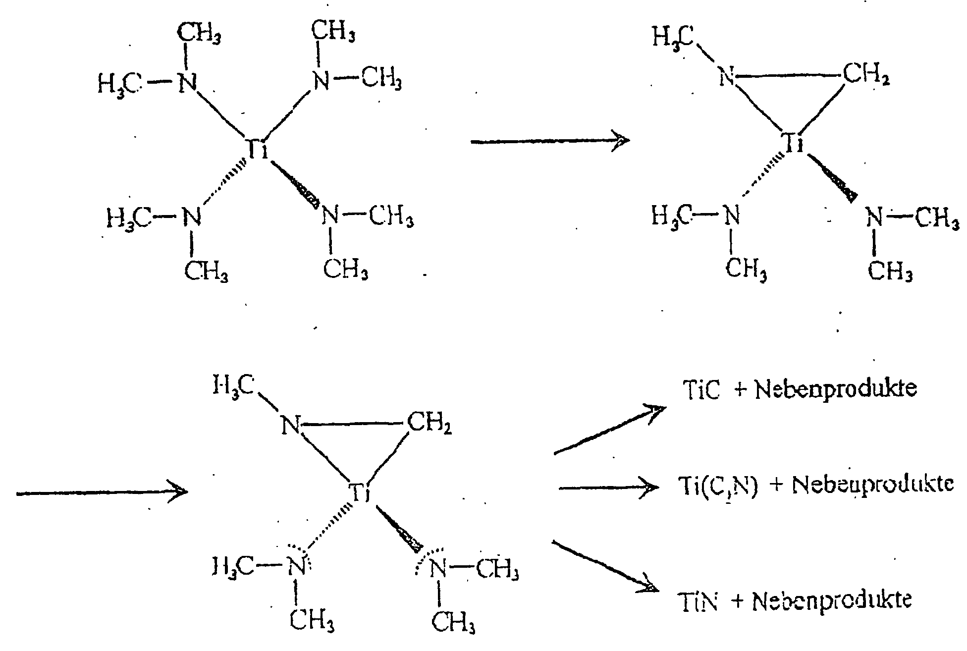
- the percentage of carbon is increasing while the proportions of metal, possibly nitrogen, Boron and oxygen increase. Which deals with the layer thickness changing composition is in Figure 1 using the example of a titanium-containing layer. How this layer structure in individual can be produced is described below become.
- the composition changes the metal-containing layer in its uppermost areas. carbon and oxygen increase while the proportions increase Slightly remove metal and nitrogen. This change is in Figure 2 also using the example of a titanium-containing layer shown.
- the layer compositions of FIGS. 1 and 2 were determined by XPS (X-ray photoelectron spectroscopy). The depth profiles were recorded by sputtering the layers with Ar + .
- Roughness measurements of the layer surfaces have shown that they are extremely smooth.
- the roughness value R a 0.001 ⁇ m was measured for the layer surfaces according to the invention.
- the layers according to the invention adhere extremely firmly to the plastic substrate. Measurements have shown tensile strengths of> 6 N / mm 2 (failure of the adhesive in the pull-off test).
- the plastic substrate Before coating impurities rid of (e.g. lubricant from the manufacturing process, of contamination from the packaging material Etc.).
- This can be done, for example, by using more liquid Cleaning agents are used, however, cleaning is advisable with the help of a low pressure plasma (see e.g. A. Mann, plasma modification of plastic surfaces for Increase in adhesive strength of metal layers, dissertation, University of Stuttgart, 1993).
- a low pressure plasma see e.g. A. Mann, plasma modification of plastic surfaces for Increase in adhesive strength of metal layers, dissertation, University of Stuttgart, 1993.
- the starting substances are not gaseous, these must be converted into the gas phase.
- the starting compounds in the reaction space becomes a Carrier gas used.
- Carrier gas come as carrier gas Nitrogen and hydrogen, as well as all noble gases.
- the carrier gases can also be reaction gases, e.g. Nitrogen. Pure oxygen is unsuitable as a carrier gas.
- a pressure of approximately 0.1 to ⁇ 50 mbar is maintained in the reactor.
- the plastic substrate to be coated in the reactor is usually heated directly.
- the temperature should not exceed 100 ° C, otherwise it will cause damage of the plastic substrate can come. Additional energy will be provided by the coupling of the plasma.
- the Starting substances in the gas space reach the Substrate surface and are there with decomposition and Reaction deposited.
- a schematic representation of the The method is shown in Figure 3. First, the Transport (1) of the starting substances using a Carrier gas. By diffusion and adsorption (2) Starting substance to the substrate surface, where a reaction (3) the starting substances take place. Volatile split off Residues are returned to the gas phase by diffusion (4) returned and then the removal takes place (5). The metal-containing reaction product, however, is on the surface deposited the substrate.
- the effect of the coupled plasma is low, and the one initially deposited on the substrate surface Substance still contains considerable amounts of carbon. These compounds have a high affinity for the surface of the plastic substrate and can partially diffuse into it, which leads to strong adhesion. With increasing Coating the substrate increases the effect of the plasma, there is more energy available, and that Reaction reactions of the starting substances always take place more complete, i.e. it's getting less and less carbon, for that but percent more metal built into the layer.
- the final is at a layer thickness of approx. 20 nm Composition of the metal-containing layer reached. With increasing Layer composition does not change more. Only after the coating process has been canceled there is still a slight change in composition the outermost part of the metal-containing layer, like the figures 1 and 2 show.
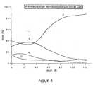
- the following diagram shows the step-by-step reaction using the starting compound Ti [N (CH 3 ) 2 ] 4 as a function of the energy available for the reaction:
- the concentration the starting compound is relative in the reaction space low to ensure that the layers grow together as early as possible and thus to achieve the smallest possible layer thickness. This results in an extremely smooth surface of the layer, causing excellent tolerance to body fluids, such as. Blood, is guaranteed.
- biocompatible surfaces can be used otherwise very good electrical conductivity non-conductive plastics are generated, which creates a Numerous new areas of application in medical technology is developed.
- the plastic substrate to be coated was on its surface cleaned in a low pressure plasma.
- nitrogen was sparged at a rate of about 5 l / h. introduced into the reactor, using a vacuum pump in the Reactor pressure of about 1 mbar was maintained.
- an external copper ring became an inductive one with 50 W.
- Ti [N (CH 3 ) 2 ] 4 was used as the liquid organometallic starting compound. Pure hydrogen flowed through the starting compound at 5 ° C. By cooling the evaporator, an excessively high concentration of the starting substance in the reaction space and thus an uneven layer structure are avoided.
- the hydrogen loaded with the starting substance flows into the reactor, in which the heated to about 100 ° C in Low pressure plasma pretreated plastic substrate (PET) is located.
- the reaction of the starting compound is controlled by additional Energy supply, namely by coupling in a low-pressure plasma triggered.
- the plasma is at a pressure in the Reaction space of approx. 1 mbar using the outside Copper rings inductively coupled at a frequency of 13.56 MHz.
- the gas becomes partial in the area of the substrate ionizes or radicals are formed. critical is that due to the reduced pressure in the gas space the gas temperature itself is only slightly increased, however, particles contained in the gas are extremely high in energy are and thus the reaction started at temperatures can be reduced significantly.
- the starting substance and the initial layer build up consists of a metal-containing compound that is still very rich in carbon is while the other components, like the metal and the nitrogen, only present in small percentages are. This leads to particularly good liability the plastic substrate, which is caused by diffusion of the initially deposited particles in the plastic reinforced becomes.
- Figure 1 shows in a layer depth of approx. 2 nm a composition consisting of approx. 40 atomic% Ti, 35 atomic% C, 15 atomic% N and 10 atomic% O. This Layer composition corresponds to the termination of the Coating process. As the reaction subsides, it changes the composition again a little, as in Figure 1 also can be seen.
- the composite material obtained was examined with XPS (X-ray photo-electron spectroscopy) for its layer composition.
- the depth profiles were recorded by sputtering the layers with Ar + . The result is shown in FIG. 1.
- the tensile strength of the metal-containing layer on the plastic substrate was also measured. Values of> 6 N / mm 2 were measured. This means that the adhesive failed during the attempt to pull it off, while the metal-containing layer adhered to the plastic substrate.
Abstract
Description
Die vorliegende Erfindung betrifft einen Verbundwerkstoff aus einem Kunststoffsubstrat und einer fest haftenden dünnen metallhaltigen Schicht. Die metallhaltige Schicht besteht aus mindestens einem Metall aus der Gruppe bestehend aus Ti, Ta, Nb, Zr und Hf und einem Anteil an mindestens einem der Elemente C, B, N, O. Die Erfindung betrifft weiterhin ein Verfahren zur Herstellung eines solchen Verbundwerkstoffes. Die erfindungsgemäßen Verbundwerkstoffe können insbesondere in der Medizintechnik eingesetzt werden.The present invention relates to a composite material a plastic substrate and a tightly adhering thin one metalliferous layer. The metal-containing layer consists of at least one metal from the group consisting of Ti, Ta, Nb, Zr and Hf and a proportion of at least one of the elements C, B, N, O. The invention further relates to a method for the production of such a composite material. The invention Composites can be used in particular in the Medical technology are used.
Die Verwendung von Kunststoffen in der Medizintechnik wird häufig durch ungenügende Oberflächeneigenschaften eingeschränkt. Dies betrifft insbesondere die Bio- und Blutverträglichkeit von z.B. Gefäßprothesen, Kathetern oder Sensoren. So können trotz großer Anstrengungen bis zum heutigen Zeitpunkt Gefäßprothesen aus Kunststoffen mit einem Durchmesser > 6 mm aufgrund der trotzdem bestehenden Thrombosegefahr nur eingeschränkt verwendet und Gefäßprothesen mit einem Durchmesser von < 6 mm in keinem Fall eingesetzt werden. Bei einem Durchmesser von < 6 mm liegt jedoch der sehr große Anwendungsbereich von künstlichen Herzkranzgefäßen (s. R. Zdrahala: Small Caliber Vascular Grafts, J. of Biomaterials Appl., Vol. 10 No. 4, Apr. 1996, S. 309-329).The use of plastics in medical technology will often limited by insufficient surface properties. This applies in particular to bio and blood tolerance from e.g. Vascular prostheses, catheters or sensors. So can, despite great efforts, to this day Vascular prostheses made of plastics with a diameter> 6 mm only limited due to the risk of thrombosis used and vascular grafts with a diameter of <6 mm are never used. With a diameter However, the very large area of application is <6 mm artificial coronary arteries (see R. Zdrahala: Small Caliber Vascular Grafts, J. of Biomaterials Appl., Vol. 10 No. 4, Apr. 1996, pp. 309-329).
Auch beim Einsatz von Kathetern kommt es, obgleich diese meist nur kurz in Kontakt zum Körper stehen, aufgrund der mangelnden Körperverträglichkeit der Kunststoffe in vielen Fällen zu Komplikationen, die eine ernsthafte Gefährdung des Patienten bedeuten können (s. R. Dujardin; Polymerstruktur und Thrombogenität, in Symposium Materialforschung - Neue Werkstoffe, S. 724-749, PLR Jülich 1994). Die Verwendung von Kunststoffen ist jedoch aufgrund ihrer vorteilhaften mechanischen Eigenschaften in vielen Bereichen der Medizintechnik unumgänglich.It also happens when catheters are used, although mostly only be in brief contact with the body due to the lack of it Body tolerance of the plastics in many cases too Complications that pose a serious risk to the patient can mean (see R. Dujardin; polymer structure and thrombogenicity, in Symposium Materials Research - New Materials, Pp. 724-749, PLR Jülich 1994). The use of plastics However, due to their advantageous mechanical properties indispensable in many areas of medical technology.
Es ist bekannt, daß Materialien auf Basis von Titan, Niob, Tantal, Zirkon oder Hafnium bioverträgliche Eigenschaften aufweisen (s. Clarke E.G. und Hickman J., An investigation into the correlation between the electrical potential of metals and their behaviour in biological fluids, J. Bone Joint Surg., Vol. 35 B (1953) 467). Außerdem wurde die ausgezeichnete Blutverträglichkeit von Titannitrid nachgewiesen (s. Y. Mitamura, Development of a ceramic heart valve, in J. of Biomaterials Applications, Vol. 4, Juli 1989, S. 33-55). Es existiert jedoch bis heute kein Material, das sowohl die vorteilhaften mechanischen Eigenschaften der Kunststoffe, als auch die hervorragenden Verträglichkeitseigenschaften der Verbindungen auf der Basis von Ti, Ta, Nb, Zr und Hf aufweist.It is known that materials based on titanium, niobium, Tantalum, zircon or hafnium have biocompatible properties (see Clarke E.G. and Hickman J., An investigation into the correlation between the electrical potential of metals and their behavior in biological fluids, J. Bone Joint Surg., Vol. 35 B (1953) 467). It also has excellent blood tolerance of titanium nitride (see Y. Mitamura, Development of a ceramic heart valve, in J. of Biomaterials Applications, Vol. 4, July 1989, pp. 33-55). However, it does exist to date no material that is both beneficial mechanical properties of the plastics, as well as the excellent Compatibility properties of the connections the base of Ti, Ta, Nb, Zr and Hf.
Es ist bekannt, daß durch chemische Gasphasenabscheidung (CVD) die Möglichkeit besteht, auch Substrate mit komplizierter Geometrie, wie sie in der Medizintechnik eingesetzt werden, zu beschichten. Allerdings sind bei den bisher meistens verwendeten anorganischen Ausgangssubstanzen zur Beschichtung mit den in Betracht kommenden Materialien Reaktionstemperaturen von > 600°C notwendig (s. S. Siveram, Chemical Vapor Depostion, Van Nostrand Reinhold, New York 1995). Weiterhin ist bekannt, daß durch den Einsatz von organometallischen oder metallorganischen Ausgangssubstanzen Beschichtungstemperaturen von ca. 300°C verwendet werden können (s. Sugiyama: Low Temperature Deposition of Metal Nitrides by Thermal Decomposition of Organometallic Compounds, J. Electrochem. Soc., Sept. 1975, S. 1545-1549). Außerdem wurde berichtet, daß die Beschichtungstemperaturen durch den Einsatz von Lasern oder durch die Einkopplung eines Niederdruckplasmas deutlich gesenkt werden können. Die niedrigste bekannte Beschichtungstemperatur von den in Frage kommenden Materialien wird mit 150°C in Zusammenhang mit der Abscheidung von Ti(C,N) und Zr(C,N) aus Ti[N(CH3)2]4 bzw. Zr[N(CH3)2]4 durch plasmaaktivierte CVD (PACVD) angegeben, wobei eine gepulste Gleichstromanregungsquelle für die Erzeugung des Plasmas eingesetzt wurde (s. K.-T. Rie et al., Studies on the synthesis of hard coatings by plasma-assisted CVD using metallo-organic compounds, Surface and Coating Technology 74-75 (1995), S.362-368). Diese Beschichtung wurde zum Verschleißschutz auf metallischen Substraten aufgebracht, auf denen eine ausreichende Haftfestigkeit problemlos erreicht werden kann.It is known that chemical vapor deposition (CVD) makes it possible to coat substrates with complicated geometries, such as those used in medical technology. However, reaction temperatures of> 600 ° C are necessary with the inorganic starting substances most commonly used for coating with the materials in question (see S. Siveram, Chemical Vapor Depostion, Van Nostrand Reinhold, New York 1995). Furthermore, it is known that the use of organometallic or organometallic starting substances enables coating temperatures of approximately 300 ° C. to be used (see Sugiyama: Low Temperature Deposition of Metal Nitrides by Thermal Decomposition of Organometallic Compounds, J. Electrochem. Soc., Sept. 1975, pp. 1545-1549). It has also been reported that the coating temperatures can be significantly reduced by using lasers or by coupling in a low-pressure plasma. The lowest known coating temperature of the materials in question is 150 ° C in connection with the deposition of Ti (C, N) and Zr (C, N) from Ti [N (CH 3 ) 2 ] 4 and Zr [N (CH 3 ) 2 ] 4 by plasma-activated CVD (PACVD), using a pulsed direct current excitation source for the generation of the plasma (see K.-T. Rie et al., Studies on the synthesis of hard coatings by plasma-assisted CVD using metallo-organic compounds, Surface and Coating Technology 74-75 (1995), pp. 362-368). This coating was applied to wear protection on metallic substrates on which sufficient adhesive strength can be achieved without any problems.
Aus der DE-A-195 06 188 ist ein Implantat für den Einsatz im menschlichen Körper bekannt, das aus einem Substrat und einer metallhaltigen Beschichtung besteht. Als Substrat werden zwar Kunststoffe erwähnt, in den Beispielen werden als Substrate jedoch Metalle verwendet. Die Beschichtung kann sowohl mittels CVD als auch mittels PVD (physikalische Gasphasenabscheidung) erfolgen. Bevorzugt wird das PVD-Verfahren, da im einleitenden Teil der DE-A-195 01 188 darauf hingewiesen wird, daß beim CVD-Verfahren eine starke Erhitzung des Substrats erforderlich ist. Im Rahmen der Lehre der DE-A-195 06 188 kommt somit das CVD-Verfahren für die Beschichtung von Kunststoffen nicht in Betracht, da diese bei den erwähnten hohen Temperaturen zerstört würden. Die in der DE-A-195 06 188 beschriebenen PVD-Beschichtungen weisen erhebliche Mängel auf:
- Es ist sehr schwierig bzw. aufwendig (wenn nicht sogar unmöglich) komplizierte Geometrien, wie z.B. bei textilen Implantaten (Gefäßprothesen, Kunststoffnetze zur Behandlung von Leistenbrüchen, etc.) durch PVD zu beschichten. Der Fachmann kennt dieses Phänomen als "Abschattungseffekt".
- Für eine ausreichende Haftung ist meist ein Aufrauhen und/oder eine Zwischenschicht erforderlich (siehe beispielsweise die Ansprüche 12 bis 14 der DE-A-195 06 188).
- Die Schichten sind mehr oder weniger porös, was nachteilig für die Korrosionsbeständigkeit ist. Weiterhin kann es durch die Poren leicht zu einer unerwünschten Adsorption von beispielsweise Blutbestandteilen kommen.
- It is very difficult or complex (if not impossible) to coat complicated geometries, such as for example with textile implants (vascular prostheses, plastic nets for the treatment of inguinal hernias, etc.) by PVD. Those skilled in the art know this phenomenon as a "shadowing effect".
- Roughening and / or an intermediate layer is usually required for adequate adhesion (see, for example, claims 12 to 14 of DE-A-195 06 188).
- The layers are more or less porous, which is disadvantageous for the corrosion resistance. Furthermore, the pores can easily lead to undesired adsorption of blood components, for example.
Aus der WO 91/08322 ist ein Verfahren zur chemischen Gasphasenabscheidung von Übergangsmetallnitriden auf verschiedenen Substraten bekannt. Bevorzugte Substrattemperaturen liegen zwischen 200 und 250°C. In Beispiel 6 werden Polyesterplatten als Substrat verwendet, die bei einer Temperatur von 150°C gehalten und mit Titannitrid beschichtet werden. Als Reaktionsgas muß bei diesem Verfahren Ammoniak eingesetzt werden. Die Zugabe des extrem reaktiven Ammoniaks führt jedoch unweigerlich zu unerwünschten Gasreaktionen (siehe: S. Intemann, "Eigenschaften von CVD-Titanverbindungsschichten aus metallorganischen Verbindungen für die Mehrlagenmetallisierung höchst integrierter Bauelemente", Dissertation TU München, 1994), was wiederum zu einem ungleichmäßigen Schichtaufbau und einem sehr ausgeprägten Abschattungseffekt führt, so daß die Vorteile des CVD-Verfahrens gegenüber dem PVD-Verfahren zunichte gemacht werden.WO 91/08322 describes a method for chemical vapor deposition of transition metal nitrides on various Known substrates. Preferred substrate temperatures are between 200 and 250 ° C. In Example 6, polyester plates used as a substrate, kept at a temperature of 150 ° C and coated with titanium nitride. As a reaction gas ammonia must be used in this process. The Addition of the extremely reactive ammonia leads inevitably unwanted gas reactions (see: S. Intemann, "Properties of CVD titanium compound layers made of organometallic Multi-layer metallization connections highly integrated components ", dissertation TU Munich, 1994), which in turn leads to an uneven layer structure and leads to a very pronounced shading effect, so that the Advantages of the CVD process compared to the PVD process be nullified.
Es ist somit noch kein zufriedenstellendes Verfahren bekannt, mit welchem man mittels CVD Kunststoffe mit metallhaltigen Schichten in zufriedenstellender Weise beschichten kann. Entweder sind die für die Beschichtung erforderlichen Substrattemperaturen zu hoch und führen zu einer Schädigung des Kunststoffsubstrats, oder die bekannten Verfahren führen zu Beschichtungen, die nicht zufriedenstellend sind. Überwiegend bestand in der Fachwelt das Vorurteil, daß Verbundwerkstoffe aus weichen Substraten und harten Schichtmaterialien nicht hergestellt werden können.A satisfactory method is therefore not yet known with which one can use plastics with metal-containing Can coat layers in a satisfactory manner. Either are the substrate temperatures required for the coating too high and lead to damage to the plastic substrate, or the known methods lead to coatings, that are not satisfactory. Mostly there was a prejudice among experts that composite materials not from soft substrates and hard layer materials can be produced.
So beschreibt A. Bolz in seiner Dissertation, Physikalische Mechanismen der Festkörper-Protein-Wechselwirkung an der Phasengrenze a-SiC:H-Fibrinogen, Universität Erlangen-Nürnberg, 1991, daß eine Beschichtung von weichen Substraten, wie z.B. Kunststoffen, mit harten Schichtmaterialien, wie z.B. SiC, wegen des auftretenden "Federbetteffektes" nicht möglich ist.This is how A. Bolz describes in his dissertation, Physikalische Mechanisms of solid-state protein interaction at the Phase boundary a-SiC: H-fibrinogen, University of Erlangen-Nuremberg, 1991 that a coating of soft substrates, such as. Plastics, with hard layer materials, e.g. SiC, not possible due to the "feather bed effect" that occurs is.
Aufgabe der vorliegenden Erfindung ist es, einen Verbundwerkstoff aus einem Kunststoff substrat und einer dünnen, fest haftenden geschlossenen metallhaltigen Schicht auf der Basis von Ti, Ta, Nb, Zr und Hf zur Verfügung zu stellen sowie ein Verfahren zu schaffen, mit dem die Herstellung eines solchen Verbundwerkstoffes gelingt. Es galt dabei ein Beschichtungsverfahren zu entwickeln, das die folgenden Anforderungen erfüllt:
- Keine Beschädigung des Kunststoffsubstrats durch den Beschichtungsvorgang, insbesondere durch zu hohe thermische Belastung.
- Ausreichende Haftfestigkeit der Schicht, trotz der extremen Unterschiede in den Eigenschaften von Schicht und Substrat, wie thermische Ausdehnung und Elastizität.
- Glatte Oberfläche der Schicht zur Minimierung von Wechselwirkungen, wie z.B. Adsorptionsvorgänge von Körperflüssigkeiten.
- No damage to the plastic substrate due to the coating process, especially due to excessive thermal stress.
- Sufficient adhesive strength of the layer, despite the extreme differences in the properties of the layer and substrate, such as thermal expansion and elasticity.
- Smooth surface of the layer to minimize interactions, such as adsorption processes of body fluids.
Die hergestellten Verbundwerkstoffe müssen dabei bioverträgliches Verhalten gegen Weichgewebe, Knochen, Blut, etc., zeigen, eine ausreichend Korrosionsbeständigkeit besitzen und darüber hinaus üblicherweise antithrombogenes Verhalten aufweisen. The composite materials produced must be biocompatible Behavior against soft tissue, bones, blood, etc., show sufficient corrosion resistance and moreover, typically have antithrombogenic behavior.
Die Aufgabe wird gelöst durch einen Verbundwerkstoff, bestehend
aus einem Kunststoffsubstrat und einer dünnen geschlossenen
metallhaltigen Schicht, dadurch gekennzeichnet, daß die
metallhaltige Schicht duktil ist, fest auf dem Kunststoffsubstrat
haftet, eine Dicke von < 2 µm aufweist und aus einer
Verbindung der Formel
- M
- ein oder mehrere Metalle aus der Gruppe Ti, Ta, Nb, Zr und Hf,
b = 0,025 bis 0,7
x = 0,2 bis 0,9
y = 0 bis 0,7
z = 0 bis 0,7
a + b + x + y + z = 1,
mit der Maßgabe, daß der Wert von a von der Substratoberfläche ausgehend von einem Wert nahe Null zur Schichtoberfläche hin zunimmt und die Kohlenstoffatome an der Basis der Schicht zu mindestens 50 % an anderen Kohlenstoffatomen durch C-C-Bindungen gebunden sind. Zur Schichtoberfläche hin können die Kohlenstoffatome zunehmend bis vollständig an Metallatomen durch M-C-Bindungen gebunden sein oder in C-C-Bindungen vorliegen.The object is achieved by a composite material consisting of a plastic substrate and a thin closed metal-containing layer, characterized in that the metal-containing layer is ductile, adheres firmly to the plastic substrate, has a thickness of <2 µm and a compound of the formula
- M
- one or more metals from the group Ti, Ta, Nb, Zr and Hf,
b = 0.025 to 0.7
x = 0.2 to 0.9
y = 0 to 0.7
z = 0 to 0.7
a + b + x + y + z = 1,
with the proviso that the value of a increases from the substrate surface from a value close to zero to the layer surface and that the carbon atoms at the base of the layer are bonded to at least 50% to other carbon atoms by CC bonds. Towards the layer surface, the carbon atoms can increasingly be bonded to metal atoms through MC bonds or be present in CC bonds.
Ein solcher Verbundwerkstoff kann hergestellt werden, indem
man
Durch die vorliegende Erfindung gelingt es, trotz der extremen Unterschiede der Eigenschaften zwischen Kunststoffsubstrat und metallhaltiger Beschichtung, haftfeste Schichten aufzubringen, wodurch eine erhebliche Verbesserung der Oberflächeneigenschaften gegenüber den unbeschichteten Kunststoffen verwirklicht werden kann und damit Kunststoffe in der Medizintechnik für beispielsweise Blutgefäße und dergleichen eingesetzt werden können.The present invention succeeds, despite the extreme Differences in properties between plastic substrate and metal-containing coating, applying adhesive layers, which significantly improves the surface properties realized compared to the uncoated plastics can be and thus plastics in medical technology used for example for blood vessels and the like can be.
Die Haftfestigkeit ist deshalb ein so großes Problem, da sich die für die Beschichtung in Frage kommenden Materialien erheblich in ihren Eigenschaften von den Kunststoffen unterscheiden. Dies sind z.B. der thermische Ausdehnungskoeffizient, der bei den Kunststoffen um ca. den Faktor 100 größer ist, und die Verformbarkeit. Insbesondere durch das unterschiedliche Ausdehnungsverhalten kann es zu erheblichen Spannungen in der Grenzschicht kommen, was letztlich zum Abplatzen der aufgetragenen Schichten führt. Diese Grenzschichtspannungen können durch einen fließenden Übergang in der Zusammensetzung minimiert werden. Dies gelingt durch das erfindungsgemäß entwickelte Beschichtungsverfahren. The adhesive strength is such a big problem because the materials in question for the coating considerably differ in their properties from plastics. These are e.g. the coefficient of thermal expansion, the for plastics is approximately 100 times larger, and the Deformability. In particular due to the different expansion behavior There can be considerable tension in the Boundary layer come, which ultimately leads to chipping of the applied Layers. These boundary layer voltages can minimized by a smooth transition in the composition become. This succeeds through the developed according to the invention Coating process.
Gegenüber den mittels PVD aufgebrachten Schichten, über welche weiter oben im Zusammenhang mit der DE-A-195 06 188 berichtet worden ist, weisen die erfindungsgemäßen Verbundwerkstoffe, deren Schichten durch CVD abgeschieden werden, wesentliche Vorteile auf:
- Die Haftung wird durch C-C-Bindungen an der Basis der Schicht und durch den gradierten Aufbau der Beschichtung erzielt, wodurch ein "sanfter" Übergang vom Kunststöffsubstrat zur keramischen Schicht erreicht wird. Das Vorliegen der C-C-Bindungen an der Basis und der M-C-Bindungen an der Oberfläche der Schicht kann durch XPS-Analysen (XPS = Röntgenstrahlelektronenspektroskopie) ermittelt werden.
- Durch diesen Aufbau ist kein Aufrauhen des Substrats zur Steigerung der Haftfestigkeit notwendig.
- Die Schichten sind extrem glatt (Ra = 0,001 µm) und geschlossen. Dadurch ist die Austauschfläche kleiner als bei rauheren und porösen Schichten. Dies führt zu einer besseren Korrosionsbeständigkeit und Bio- und Blutverträglichkeit als bei rauheren und porösen Schichten.
- Adhesion is achieved by CC bonds at the base of the layer and by the graded structure of the coating, which results in a "smooth" transition from the plastic substrate to the ceramic layer. The presence of the CC bonds on the base and the MC bonds on the surface of the layer can be determined by XPS analyzes (XPS = X-ray electron spectroscopy).
- Due to this structure, no roughening of the substrate is necessary to increase the adhesive strength.
- The layers are extremely smooth (R a = 0.001 µm) and closed. This means that the exchange area is smaller than with rougher and porous layers. This leads to better corrosion resistance and bio- and blood compatibility than with rougher and porous layers.
In den Zeichnungen zeigen
- die
Figur 1 - eine XPS-Analyse der Beschichtung in Abhängigkeit von der Schichttiefe unmittelbar nach der Beschichtung,
- die
Figur 2 - eine entsprechende Analyse nach zweiwöchiger Lagerung des beschichteten Substrats an Luft, und
- die
Figur 3 - eine schematische Darstellung des erfindungsgemäßen Beschichtungsverfahrens.
- the figure 1
- an XPS analysis of the coating as a function of the layer depth immediately after coating,
- the figure 2
- a corresponding analysis after two weeks of storage of the coated substrate in air, and
- the figure 3
- is a schematic representation of the coating method according to the invention.
Als Kunststoffsubstrat der erfindungsgemäßen Verbundwerkstoffe eignen sich insbesondere Polyethylenterephthalat (PET), Polyurethan (PUR), Polytetrafluorethylen (PTFE), Polyamid (PA) und Polypropylen (PP), die auch bislang schon zur Herstellung von Gefäßprothesen verwendet worden sind (siehe R. Zdrahala: Small Caliber Vascular Grafts, Part I: State of the Art; Journal of Biomaterials Applications, Vol. 10, April 1996, Seiten 309-329). As a plastic substrate of the composite materials according to the invention polyethylene terephthalate (PET), polyurethane are particularly suitable (PUR), polytetrafluoroethylene (PTFE), polyamide (PA) and Polypropylene (PP), which has also been used to manufacture Vascular prostheses have been used (see R. Zdrahala: Small Caliber Vascular Grafts, Part I: State of the Art; Journal of Biomaterials Applications, vol. 10, April 1996, pages 309-329).
Weitere Kunststoffe, die für die vorliegenden Zwecke in Betracht kommen können, sind Polyetheretherketon (PEEK), Polysulfon (PSU), Polybutylenterephthalat (PBT), Polyethersulfon (PES), Polyimid (PI), Polycarbonat (PC), Polyetherimid (PEI), Polyamidimid (PAI) und dergleichen oder auch Silikone. Alle diese Kunststoffe sind bei einer Temperatur von ca. 100°, bei der die Beschichtung mit der metallhaltigen Schicht erfolgt, stabil.Other plastics that are considered for the present purposes can come are polyether ether ketone (PEEK), polysulfone (PSU), polybutylene terephthalate (PBT), polyether sulfone (PES), polyimide (PI), polycarbonate (PC), polyetherimide (PEI), Polyamideimide (PAI) and the like or also silicones. All these plastics are at a temperature of approx. 100 ° which is coated with the metal-containing layer, stable.
Auf dem Kunststoffsubstrat befindet sich die dünne metallhaltige Schicht, die eine Dicke von < 2 µm besitzt. Vorzugsweise liegt die Schichtdicke innerhalb eines Bereiches von 5 bis 700 nm, insbesondere innerhalb eines Bereiches von 5 bis 500 nm.The thin metal-containing one is on the plastic substrate Layer with a thickness of <2 µm. Preferably the layer thickness is within a range of 5 up to 700 nm, in particular within a range from 5 to 500 nm.
Die metallhaltige Schicht besteht aus einer Metallverbindung
der Formel
M bedeutet ein oder mehrere Metalle aus der Gruppe Ti, Ta, Nb, Zr und Hf.M denotes one or more metals from the group Ti, Ta, Nb, Zr and Hf.
a bedeutet 0,025 bis 0,9; b bedeutet 0,025 bis 0,7; x bedeutet 0,2 bis 0,90; y bedeutet 0 bis 0,7 und z bedeutet 0 bis 0,7.a means 0.025 to 0.9; b represents 0.025 to 0.7; x means 0.2 to 0.90; y means 0 to 0.7 and z means 0 to 0.7.
a + b + x + y + z betragen zusammen gleich 1.a + b + x + y + z are equal to 1.
Je nach verwendetem Trägergas kann in den Schichten ein gewisser Anteil an Wasserstoff vorliegen.Depending on the carrier gas used, a can be present in the layers some hydrogen is present.
Es gilt weiterhin die Maßgabe, daß der Wert von a von der Substratoberfläche ausgehend von einem Wert nahe 0 zur Schichtoberfläche hin zunimmt. Dies ist für eine gute Haftung der metallhaltigen Schicht einer Substratoberfläche wichtig. Der Kohlenstoffgehalt ist an der Basis der metallhaltigen Schicht, also nahe der Substratoberfläche, besonders hoch. x nimmt in der Regel einen Wert von nahe 0,9 an. Bei zunehmender Schichtdicke verändert sich die Zusammensetzung der metallhaltigen Schicht beträchtlich. Der Anteil an Kohlenstoff nimmt ab, während die Anteile an Metall, gegebenenfalls Stickstoff, Bor und Sauerstoff zunehmen. Die sich mit der Schichtdicke ändernde Zusammensetzung ist in Figur 1 am Beispiel einer titanhaltigen Schicht dargestellt. Wie dieser Schichtaufbau im einzelnen hergestellt werden kann, wird weiter unten beschrieben werden.The condition that the value of a is different from the Substrate surface starting from a value close to 0 to Layer surface increases. This is for good liability the metal-containing layer of a substrate surface is important. The carbon content is at the base of the metal Layer, i.e. close to the substrate surface, particularly high. x usually assumes a value of close to 0.9. With increasing Layer thickness changes the composition of the metal-containing Layer considerably. The percentage of carbon is increasing while the proportions of metal, possibly nitrogen, Boron and oxygen increase. Which deals with the layer thickness changing composition is in Figure 1 using the example of a titanium-containing layer. How this layer structure in individual can be produced is described below become.
Vorzugsweise gilt für die Werte von a, b, x, y und z folgendes:
Nach der Lagerung an Luft verändert sich die Zusammensetzung der metallhaltigen Schicht in ihren obersten Bereichen. Kohlenstoff und Sauerstoff nehmen zu, während die Anteile an Metall und Stickstoff leicht abnehmen. Diese Veränderung ist in Figur 2 ebenfalls am Beispiel einer titanhaltigen Schicht dargestellt. After storage in air, the composition changes the metal-containing layer in its uppermost areas. carbon and oxygen increase while the proportions increase Slightly remove metal and nitrogen. This change is in Figure 2 also using the example of a titanium-containing layer shown.
Die Schichtzusammensetzungen der Figuren 1 und 2 wurden durch XPS (X-ray photoelectron spectroscopy) bestimmt. Dabei wurden die Tiefenprofile durch Absputtern der Schichten mit Ar+ aufgenommen.The layer compositions of FIGS. 1 and 2 were determined by XPS (X-ray photoelectron spectroscopy). The depth profiles were recorded by sputtering the layers with Ar + .
Eines der wenigen bislang bekannten Kriterien für gute Blutverträglichkeit ist neben einer glatten Oberfläche eine Mindestleitfähigkeit von L > 10-4 (Ohm·cm)-1 (siehe A. Bolz, Physikalische Mechanismen der Festkörper-Protein-Wechselwirkung an der Phasengrenze a-SiC:H-Fibrinogen, Dissertation, Universität Erlangen-Nürnberg, 1991). Erfindungsgemäß sind Leitfähigkeiten der metallhaltigen Schicht unmittelbar nach ihrer Herstellung von L = 2,1 (Ohm·cm)-1 gemessen worden. Nach 3-tägiger Lagerung an Luft betrug L = 0,18 (Ohm·cm)-1.In addition to a smooth surface, one of the few criteria known to date for good blood tolerance is a minimum conductivity of L> 10 -4 (Ohm · cm) -1 (see A. Bolz, physical mechanisms of the solid-state protein interaction at the phase boundary a-SiC: H-fibrinogen, dissertation, University of Erlangen-Nuremberg, 1991). According to the invention, conductivities of the metal-containing layer were measured immediately after its production of L = 2.1 (Ohm · cm) -1 . After storage in air for 3 days, L = 0.18 (ohm.cm) -1 .
Rauhigkeitsmessungen der Schichtoberflächen haben ergeben, daß diese außerordentlich glatt sind. Bei den erfindungsgemäßen Schichtoberflächen ist der Rauhigkeitswert Ra = 0,001 µm gemessen worden. Im Vergleich dazu liegen die Rauhigkeitswerte der einzigen in der-Literatur beschriebenen CVD-Schichten zur Steigerung der Blutverträglichkeit wesentlich höher, nämlich bei: Ra = 0,43 µm und Rt = 2,4 µm (siehe I. Dion, TiN-Coating: Surface Characterization and Haemocompatibility, Bio-materials, Vol. 14, Nr. 3, 1993, Seiten 169-176).Roughness measurements of the layer surfaces have shown that they are extremely smooth. The roughness value R a = 0.001 μm was measured for the layer surfaces according to the invention. In comparison, the roughness values of the only CVD layers described in the literature for increasing the blood tolerance are much higher, namely: R a = 0.43 µm and R t = 2.4 µm (see I. Dion, TiN coating : Surface Characterization and Haemocompatibility, Bio-materials, Vol. 14, No. 3, 1993, pages 169-176).
Die erfindungsgemäßen Schichten haften außerordentlich fest am Kunststoffsubstrat. Messungen haben Zughaftfestigkeiten von > 6 N/mm2 (Versagen des Klebers beim Abzugsversuch) ergeben.The layers according to the invention adhere extremely firmly to the plastic substrate. Measurements have shown tensile strengths of> 6 N / mm 2 (failure of the adhesive in the pull-off test).
Um eine gute Haftfestigkeit zwischen metallhaltiger Beschichtung und Kunststoffsubstrat zu erreichen, ist es notwendig, das Kunststoffsubstrat vor der Beschichtung von Verunreinigungen zu befreien (beispielsweise von Gleitmittel vom Herstellungsprozeß, von Verunreinigungen vom Verpackungsmaterial etc.). Dies kann beispielsweise durch den Einsatz flüssiger Reinigungsmittel erfolgen, zweckmäßig wird jedoch die Reinigung mit Hilfe eines Niederdruckplasmas durchgeführt (siehe z.B. A. Mann, Plasmamodifikation von Kunststoffoberflächen zur Haftfestigkeitssteigerung von Metallschichten, Dissertation, Universität Stuttgart, 1993). Im Niederdruckplasma werden die Gase angeregt (ionisiert, radikalisiert) und treffen mit zum Teil hoher kinetischer Energie auf das Substrat bzw. auf die Verunreinigung. Dadurch werden die Verunreinigungen abgetragen oder zersetzt und können über die Gasphase abtransportiert werden. Durch dieses Behandlungsverfahren kann es darüber hinaus zu einer Aktivierung der Substratoberfläche kommen, was schließlich zu einer gesteigerten Haftfestigkeit führt.To ensure good adhesion between the metal-containing coating and plastic substrate, it is necessary the plastic substrate before coating impurities rid of (e.g. lubricant from the manufacturing process, of contamination from the packaging material Etc.). This can be done, for example, by using more liquid Cleaning agents are used, however, cleaning is advisable with the help of a low pressure plasma (see e.g. A. Mann, plasma modification of plastic surfaces for Increase in adhesive strength of metal layers, dissertation, University of Stuttgart, 1993). In low pressure plasma, the Gases excited (ionized, radicalized) and hit with the Part of high kinetic energy on the substrate or on the Pollution. This removes the contaminants or decomposes and can be removed via the gas phase become. Through this treatment procedure, it can go beyond that come to an activation of the substrate surface what eventually leads to increased adhesive strength.
Als Ausgangsmaterialien für die Herstellung der metallhaltigen Schicht eignen sich zahlreiche metallorganische und organometallische Verbindungen. Bei den Metallen Titan, Zirkonium und Hafnium kommen beispielsweise die folgenden Verbindungsgruppen in Betracht:
- Amidoverbindungen:
- z.B. M[N[CH3]2]4, M[N[C2H5]2]4, M[N(CH2) (C[CH3]2)]4
- Imidoverbindungen:
- z.B. ((NtBu)M[N(CH3)2]2)2, ((NtBu)M[N(C2H5)2]2)2
- Verbindungen mit M-C-Bindung:
- z.B. M(CH2 tBu)4, (C5H5)2MCl2
- amido compounds:
- e.g. M [N [CH 3 ] 2 ] 4 , M [N [C 2 H 5 ] 2 ] 4 , M [N (CH 2 ) (C [CH 3 ] 2 )] 4
- imido compounds:
- e.g. ((N t Bu) M [N (CH 3 ) 2 ] 2 ) 2 , ((N t Bu) M [N (C 2 H 5 ) 2 ] 2 ) 2
- MC bond connections:
- e.g. M (CH 2 t Bu) 4 , (C 5 H 5 ) 2 MCl 2
Für die Metalle Tantal und Niob kommen die folgenden Verbindungsgruppen in Betracht:
- Amidoverbindungen:
- z.B. M[N[CH3]2]5, M[N[C2H5]2]5
- Imidoverbindungen:
- z.B. [N[C2H5]2]3M=NtBu
- amido compounds:
- eg M [N [CH 3 ] 2 ] 5 , M [N [C 2 H 5 ] 2 ] 5
- imido compounds:
- eg [N [C 2 H 5 ] 2 ] 3 M = N t Bu
Sofern die Ausgangssubstanzen nicht gasförmig vorliegen, müssen diese in die Gasphase überführt werden. Für den Transport der Ausgangsverbindungen in den Reaktionsraum wird ein Trägergas verwendet. Als Trägergas kommen beispielsweise Stickstoff und Wasserstoff, sowie alle Edelgase in Betracht. Die Trägergase können auch Reaktionsgase sein, z.B. Stickstoff. Reiner Sauerstoff ist als Trägergas ungeeignet. If the starting substances are not gaseous, these must be converted into the gas phase. For the transport the starting compounds in the reaction space becomes a Carrier gas used. For example, come as carrier gas Nitrogen and hydrogen, as well as all noble gases. The carrier gases can also be reaction gases, e.g. Nitrogen. Pure oxygen is unsuitable as a carrier gas.
Im Reaktor wird ein Druck von ca. 0,1 bis < 50 mbar aufrechterhalten.A pressure of approximately 0.1 to <50 mbar is maintained in the reactor.
Das im Reaktor befindliche, zu beschichtende Kunststoffsubstrat wird in der Regel direkt beheizt. Die Temperatur sollte nicht mehr als 100°C betragen, da es sonst zu einer Schädigung des Kunststoffsubstrats kommen kann. Zusätzliche Energie wird durch die Einkoppelung des Plasmas zur Verfügung gestellt. Die im Gasraum befindlichen Ausgangssubstanzen gelangen an die Substratoberfläche und werden dort unter Zersetzung und Reaktion abgeschieden. Eine schematische Darstellung des Verfahrens ist der Figur 3 zu entnehmen. Zunächst erfolgt der Antransport (1) der Ausgangssubstanzen mit Hilfe eines Trägergases. Durch Diffusion und Adsorption (2) gelangt die Ausgangssubstanz an die Substratoberfläche, wo eine Reaktion (3) der Ausgangssubstanzen stattfindet. Flüchtige abgespaltene Reste werden durch Diffusion (4) wieder in die Gasphase zurückgeführt und dann erfolgt der Abtransport (5). Das metallhaltige Reaktionsprodukt wird dagegen auf der Oberfläche des Substrats abgeschieden.The plastic substrate to be coated in the reactor is usually heated directly. The temperature should not exceed 100 ° C, otherwise it will cause damage of the plastic substrate can come. Additional energy will be provided by the coupling of the plasma. The Starting substances in the gas space reach the Substrate surface and are there with decomposition and Reaction deposited. A schematic representation of the The method is shown in Figure 3. First, the Transport (1) of the starting substances using a Carrier gas. By diffusion and adsorption (2) Starting substance to the substrate surface, where a reaction (3) the starting substances take place. Volatile split off Residues are returned to the gas phase by diffusion (4) returned and then the removal takes place (5). The metal-containing reaction product, however, is on the surface deposited the substrate.
Zunächst ist die Wirkung des eingekoppelten Plasmas gering, und die zunächst auf der Substratoberfläche abgeschiedene Substanz enthält noch beträchtliche Mengen an Kohlenstoff. Diese Verbindungen haben eine hohe Affinität zur Oberfläche des Kunststoffsubstrats und können in dieses zum Teil eindiffundieren, wodurch es zu einer starken Haftung kommt. Mit zunehmender Beschichtung des Substrats erhöht sich die Wirkung des Plasmas, es steht mehr Energie zur Verfügung, und die Umsetzungsreaktionen der Ausgangssubstanzen verlaufen immer vollständiger, d.h. es wird immer weniger Kohlenstoff, dafür aber prozentual mehr Metall in die Schicht eingebaut.First of all, the effect of the coupled plasma is low, and the one initially deposited on the substrate surface Substance still contains considerable amounts of carbon. These compounds have a high affinity for the surface of the plastic substrate and can partially diffuse into it, which leads to strong adhesion. With increasing Coating the substrate increases the effect of the plasma, there is more energy available, and that Reaction reactions of the starting substances always take place more complete, i.e. it's getting less and less carbon, for that but percent more metal built into the layer.
Dies führt letztlich dazu, daß durch den hohen Kohlenstoffgehalt der anfänglich abgeschiedenen Schicht eine innige fest haftende Verbindung zwischen der Kunststoffsubstratoberfläche und der metallhaltigen Schicht entsteht.This ultimately leads to the high carbon content the initially deposited layer an intimate firm adhesive connection between the plastic substrate surface and the metal-containing layer is formed.
Bei einer Schichtdicke von ca. 20 nm ist die endgültige Zusammensetzung der metallhaltigen Schicht erreicht. Bei zunehmender Schichtdicke ändert sich die Zusammensetzung nicht mehr. Erst nach dem Abbruch des Beschichtungsverfahrens kommt es noch zu einer geringfügigen Änderung der Zusammensetzung in dem äußersten Teil der metallhaltigen Schicht, wie die Figuren 1 und 2 zeigen.The final is at a layer thickness of approx. 20 nm Composition of the metal-containing layer reached. With increasing Layer composition does not change more. Only after the coating process has been canceled there is still a slight change in composition the outermost part of the metal-containing layer, like the figures 1 and 2 show.
Das nachfolgende Schema zeigt die stufenweise zunehmende Reaktion
am Beispiel der Ausgangsverbindung Ti[N(CH3)2]4 in Abhängingkeit
zunehmend vorhandener Energie für die Reaktion:
Wie der Figur 1 zu entnehmen ist, besteht die metallhaltige Schicht in einer Schichttiefe von ca. 2 nm, was zeitlich dem Abbrechen der Beschichtungsreaktion entspricht, aus ca. 40 Atom-% Ti, 35 Atom-% C, 15 Atom-% N und 10 Atom-% O. Eine solche Zusammensetzung weist eine außerordentlich günstige Verträglichkeit mit Blut auf, so daß sich derartige beschichtete Kunststoffsubstrate hervorragend zur Herstellung von künstlichen Gefäßimplantaten eignen.As can be seen in Figure 1, there is the metal-containing Layer in a layer depth of approx. 2 nm, which corresponds to the time Canceling the coating reaction corresponds to approx. 40 Atomic% Ti, 35 atomic% C, 15 atomic% N and 10 atomic% O. One such Composition shows an extremely favorable tolerance with blood, so that such was coated Plastic substrates excellent for the production of artificial Vascular implants are suitable.
Bei dem erfindungsgemäßen Verfahren ist es erstmalig gelungen, die Beschichtungstemperaturen auf ca. 100°C abzusenken und somit die erforderlichen Temperaturen einzuhalten, bei denen das Kunststoffsubstrat nicht geschädigt wird. Insbesondere bei Verwendung von Wasserstoff als Trägergas sind sehr niedrige Beschichtungstemperaturen möglich.With the method according to the invention, it has been possible for the first time lowering the coating temperatures to approx. 100 ° C and thus maintain the required temperatures at which the Plastic substrate is not damaged. Especially at Use of hydrogen as a carrier gas is very low Coating temperatures possible.
Wie in der Figur 2 gezeigt, nimmt die Oberfläche der metallhaltigen Schicht im Laufe der Zeit Sauerstoff auf. Wenn dies vermieden werden soll, eignet sich eine Nachbehandlung im Stickstoffplasma. Diese führt zu einer deutlichen Erhöhung des Stickstoffgehaltes der Oberfläche der metallhaltigen Schicht, und es kommt dadurch zu einer erheblichen Reduzierung der nachträglichen Sauerstoffaufnahme.As shown in Figure 2, the surface of the metal-containing Layer oxygen over time. If this Aftercare should be avoided Nitrogen plasma. This leads to a significant increase in Nitrogen content of the surface of the metal-containing layer, and there is a significant reduction in the subsequent oxygen uptake.
Durch das erfindungsgemäße Verfahren ist eine Beschichtung von Kunststoffsubstraten mit komplizierten Geometrien möglich, da die Ausgangssubstanz vor der Reaktion gleichmäßig mit dem zu beschichtenden Substrat in Kontakt kommt. Die Konzentration der Ausgangsverbindung ist dabei im Reaktionsraum relativ niedrig, um ein möglichst frühes Zusammenwachsen der Schichten und somit eine möglichst geringe Schichtdicke zu erreichen. Dies führt zu einer extrem glatten Oberfläche der Schicht, wodurch die hervorragende Verträglichkeit gegenüber Körperflüssigkeiten, wie z.B. Blut, gewährleistet wird.A coating of Plastic substrates with complicated geometries possible because the starting substance before the reaction evenly with the coating substrate comes into contact. The concentration the starting compound is relative in the reaction space low to ensure that the layers grow together as early as possible and thus to achieve the smallest possible layer thickness. This results in an extremely smooth surface of the layer, causing excellent tolerance to body fluids, such as. Blood, is guaranteed.
Durch die Erfindung können bioverträgliche Oberflächen mit einer sehr guten elektrischen Leitfähigkeit auf ansonsten nicht leitenden Kunststoffen erzeugt werden, wodurch eine Vielzahl von neuen Anwendungsgebieten in der Medizintechnik erschlossen wird.By means of the invention, biocompatible surfaces can be used otherwise very good electrical conductivity non-conductive plastics are generated, which creates a Numerous new areas of application in medical technology is developed.
Zunächst wurde das zu beschichtende Kunststoffsubstrat an seiner Oberfläche in einem Niederdruckplasma gereinigt. Dazu wurde Stickstoff mit einer Geschwindigkeit von ca. 5 l/h i.N. in den Reaktor eingeleitet, wobei mittels einer Vakuumpumpe im Reaktor ein Druck von ca. 1 mbar aufrechterhalten wurde. Durch einen außen liegenden Kupferring wurde mit 50 W ein induktives Plasma mit einer Frequenz von 13,56 MHz eingekoppelt. Die Behandlungsdauer betrug ca. 3 min (sie kann bei Bedarf abgekürzt werden).First, the plastic substrate to be coated was on its surface cleaned in a low pressure plasma. To nitrogen was sparged at a rate of about 5 l / h. introduced into the reactor, using a vacuum pump in the Reactor pressure of about 1 mbar was maintained. By an external copper ring became an inductive one with 50 W. Plasma coupled in at a frequency of 13.56 MHz. The duration of treatment was approx. 3 min (it can be shortened if necessary become).
Als flüssige organometallische Ausgangsverbindung wurde Ti[N(CH3)2]4 eingesetzt. Die Ausgangsverbindung wurde bei 5°C mit reinem Wasserstoff durchströmt. Durch die Kühlung des Verdampfers wird eine zu hohe Konzentration der Ausgangssubstanz im Reaktionsraum und damit ein ungleichmäßiger Schichtaufbau vermieden.Ti [N (CH 3 ) 2 ] 4 was used as the liquid organometallic starting compound. Pure hydrogen flowed through the starting compound at 5 ° C. By cooling the evaporator, an excessively high concentration of the starting substance in the reaction space and thus an uneven layer structure are avoided.
Der mit der Ausgangssubstanz beladene Wasserstoff strömt in den Reaktor, in welchem sich das auf ca. 100°C aufgeheizte, im Niederdruckplasma vorbehandelte Kunststoffsubstrat (PET) befindet. Die Reaktion der Ausgangsverbindung wird durch zusätzliche Energiezufuhr, nämlich durch Einkoppeln eines Niederdruckplasmas ausgelöst. Das Plasma wird bei einem Druck im Reaktionsraum von ca. 1 mbar mittels des außen liegenden Kupferrings bei einer Frequenz von 13,56 MHz induktiv eingekoppelt. Dadurch wird das Gas im Bereich des Substrats teilweise ionisiert bzw. es kommt zu einer Radikalbildung. Entscheidend ist dabei, daß durch den reduzierten Druck im Gasraum die Gastemperatur selbst nur unwesentlich erhöht wird, jedoch Teilchen im Gas enthalten sind, die extrem energiereich sind und somit die Reaktion bei Temperaturen in Gang gesetzt werden kann, die erheblich reduziert sind. The hydrogen loaded with the starting substance flows into the reactor, in which the heated to about 100 ° C in Low pressure plasma pretreated plastic substrate (PET) is located. The reaction of the starting compound is controlled by additional Energy supply, namely by coupling in a low-pressure plasma triggered. The plasma is at a pressure in the Reaction space of approx. 1 mbar using the outside Copper rings inductively coupled at a frequency of 13.56 MHz. As a result, the gas becomes partial in the area of the substrate ionizes or radicals are formed. critical is that due to the reduced pressure in the gas space the gas temperature itself is only slightly increased, however, particles contained in the gas are extremely high in energy are and thus the reaction started at temperatures can be reduced significantly.
Zunächst kommt es nur zu einer teilweisen Reaktion der Ausgangssubstanz und der anfängliche Schichtaufbau besteht aus einer metallhaltigen Verbindung, die noch sehr reich an Kohlenstoff ist, während die anderen Bestandteile, wie das Metall und der Stickstoff, nur in geringen prozentualen Anteilen vorhanden sind. Dies führt zu einer besonders guten Haftung an dem Kunststoffsubstrat, die durch eine Diffusion der anfänglich abgeschiedenen Teilchen in den Kunststoff noch verstärkt wird.At first there is only a partial reaction of the starting substance and the initial layer build up consists of a metal-containing compound that is still very rich in carbon is while the other components, like the metal and the nitrogen, only present in small percentages are. This leads to particularly good liability the plastic substrate, which is caused by diffusion of the initially deposited particles in the plastic reinforced becomes.
Durch den beginnenden Aufbau der metallhaltigen Schicht verändern sich die Oberflächeneigenschaften des Substrats und die Wirkung des eingekoppelten Plasmas auf das nun schon teilweise beschichtete Substrat nimmt zu. Durch die zunehmend günstigeren Energieverhältnisse kommt es zu weitergehenden Reaktionen der Ausgangsverbindungen, d.h., die Zusammensetzung der abgeschiedenen Schichten verändert sich im Laufe der Zeit, wobei der Kohlenstoffgehalt stetig abnimmt, während der Gehalt an Stickstoff und Metall zunimmt.Change through the beginning of the build-up of the metal-containing layer the surface properties of the substrate and the Effect of the coupled plasma on the now partially coated substrate increases. Because of the increasingly cheaper Energy relationships lead to further reactions of the starting compounds, i.e. the composition of the deposited ones Layers change over time, being the carbon content decreases steadily while the content of Nitrogen and metal increases.
Der Beschichtungsvorgang wurde bei einer Schichtdicke von ca. 10 nm abgebrochen. Die Figur 1 zeigt in einer Schichttiefe von ca. 2 nm eine Zusammensetzung, die aus ca. 40 Atom-% Ti, 35 Atom-% C, 15 Atom-% N und 10 Atom-% O besteht. Diese Schichtzusammensetzung entspricht zeitlich dem Abbruch des Beschichtungsverfahrens. Im Abklingen der Reaktion ändert sich die Zusammensetzung wiederum ein wenig, wie der Figur 1 ebenfalls zu entnehmen ist.The coating process was carried out at a layer thickness of approx. 10 nm canceled. Figure 1 shows in a layer depth of approx. 2 nm a composition consisting of approx. 40 atomic% Ti, 35 atomic% C, 15 atomic% N and 10 atomic% O. This Layer composition corresponds to the termination of the Coating process. As the reaction subsides, it changes the composition again a little, as in Figure 1 also can be seen.
Der erhaltene Verbundwerkstoff wurde mit XPS (X-ray photo-electron spectroscopy) auf seine Schichtzusammensetzung hin untersucht. Die Tiefenprofile wurden durch Absputtern der Schichten mit Ar+ aufgenommen. Das Ergebnis ist in Figur 1 gezeigt. The composite material obtained was examined with XPS (X-ray photo-electron spectroscopy) for its layer composition. The depth profiles were recorded by sputtering the layers with Ar + . The result is shown in FIG. 1.
Eine erneute Untersuchung der Schichtzusammensetzung nach Lagerung des Verbundwerkstoffes an Luft ergab nach 2 Wochen eine Zusammensetzung, die der Figur 2 entspricht. Der Kohlenstoffgehalt und auch der Sauerstoffgehalt hatten aufgrund von Sauerstoffaufnahme und Oberflächenverunreinigungen zugenommen.A new examination of the layer composition after Storage of the composite in air resulted in 2 weeks a composition that corresponds to Figure 2. The carbon content and also had the oxygen content due to Oxygen uptake and surface contamination increased.
Eine Messung der Leitfähigkeit der Schichten ergab unmittelbar
nach der Beschichtung einen Wert von L = 2,1 (Ohm·cm)-1
und nach 3-tägiger Lagerung an Luft einen Wert von L = 0,18
(Ohm·cm)-1.A measurement of the conductivity of the layers resulted immediately after the coating has a value of L = 2.1 (ohm-cm) -1 and
Weiterhin wurde die Zughaftfestigkeit der metallhaltigen Schicht am Kunststoffsubstrat gemessen. Es wurden Werte von > 6 N/mm2 gemessen. Das heißt, daß beim Abzugsversuch der Kleber versagte, während die metallhaltige Schicht am Kunststoffsubstrat haften blieb.The tensile strength of the metal-containing layer on the plastic substrate was also measured. Values of> 6 N / mm 2 were measured. This means that the adhesive failed during the attempt to pull it off, while the metal-containing layer adhered to the plastic substrate.
Schließlich wurden gemäß dem Verfahren, das in dem oben erwähnten Artikel von Dion et al. beschrieben ist, Rauhigkeitsmessungen der metallhaltigen Schichten durchgeführt. Es ergab sich der Wert von Ra = 0,001 µm.Finally, according to the method described in the above-mentioned article by Dion et al. roughness measurements of the metal-containing layers are carried out. The result was R a = 0.001 µm.
Claims (10)
- Composite composed of a plastic substrate and a thin, continuous metal-containing layer, characterized in that the metal-containing layer is ductile, adheres firmly to the plastic substrate, has a thickness of < 2 µm and is composed of a compound corresponding to the formulaprovided that the value of a, starting from the substrate surface, increases from a value approximating zero towards the layer surface, and at least 50 % of the carbon atoms at the base of the layer are bound to other carbon atoms by C-C bonds.M is one or more metals of the group Ti, Ta, Nb, Zr and Hf,a = 0.025 to 0.9b = 0.025 to 0.7x = 0.2 to 0.9y = 0 to 0.7z = 0 to 0.7a+b+x+y+z = 1
- Composite according to claim 1, characterized in that the plastic substrate is composed of polyethylene terephthalate, polyurethane, polytetrafluoroethylene, polyamide or polypropylene.
- Composite according to claims 1 or 2, characterized in that M = Ti.
- Composite according to claims 1 to 3, characterized in that the following applies to the values of a, b, x, y and z:(i) at the base of the metal-containing layer:a = 0.025 - 0.1b = 0.025 - 0.2x = 0.8 - 0.9y = 0 - 0.1z = 0 - 0.1(ii) as the thickness of the metal-containing layer increases, the value of a increases, and(iii) near the surface of the metal-containing layer:a = 0.2 - 0.9b = 0.025 - 0.7x = 0 - 0.7y = 0 - 0.7z = 0 - 0.5.
- Composite according to claims 1 to 4, the coating of which additionally contains hydrogen.
- Process for the production of a composite according to claims 1 to 5, characterized in thata) the plastic substrate is cleaned,b) a suitable metallo-organic or organometallic starting compound is selected,c) the metallo-organic or organometallic starting compound, if it is not gaseous, is converted to the gas phase,d) the gaseous metallo-organic or organometallic compound starting compound is conveyed by means of a carrier gas to a reactor in which is situated the plastic substrate, on the surface of which the starting compounds are deposited by chemical vapour deposition accompanied by decomposition and reaction,e) energy is passed to the substrate by plasma coupling and optionally direct heating so that a temperature of 100°C is not exceeded, a carbon and metal gradient in the direction of the layer thickness being achieved by the action of the plasma,f) a pressure of 0.1 to < 50 mbar is maintained in the reaction chamber, andg) the composite is then stored in air.
- Process according to claim 6, characterized in that hydrogen is used as carrier gas.
- Process according to claim 6 or 7, characterized in that the metallo-organic or organometallic compound used is
M[N[CH3]2]4, M[N[C2H5]2]4, M[N(CH2)(C[CH3]2)]4,
((NtBu)M[N(CH3)2]2)2, ((NtBu)M[N(C2H5)2]2)2,
M(CH2 tBu)4 and/or (C5H5)2MCl2
where M = Ti, Zr or Hf. - Process according to claim 8, characterized in that the metallo-organic or organometallic compound used is Ti[N(CH3)2]4.
- Process according to claims 6 or 7, characterized in that the metallo-organic or organometallic compound used is M[N[CH3)2]5, M[N[C2H5]2]5, and/or [N[C2H5]2]3M=NtBu where M = Ta or Nb.
Applications Claiming Priority (2)
| Application Number | Priority Date | Filing Date | Title |
|---|---|---|---|
| DE19736449 | 1997-08-21 | ||
| DE19736449A DE19736449A1 (en) | 1997-08-21 | 1997-08-21 | Composite |
Publications (2)
| Publication Number | Publication Date |
|---|---|
| EP0897997A1 EP0897997A1 (en) | 1999-02-24 |
| EP0897997B1 true EP0897997B1 (en) | 2003-02-26 |
Family
ID=7839760
Family Applications (1)
| Application Number | Title | Priority Date | Filing Date |
|---|---|---|---|
| EP98115821A Expired - Lifetime EP0897997B1 (en) | 1997-08-21 | 1998-08-21 | Composite material |
Country Status (5)
| Country | Link |
|---|---|
| US (1) | US6057031A (en) |
| EP (1) | EP0897997B1 (en) |
| JP (1) | JP4420482B2 (en) |
| AT (1) | ATE233328T1 (en) |
| DE (2) | DE19736449A1 (en) |
Cited By (20)
| Publication number | Priority date | Publication date | Assignee | Title |
|---|---|---|---|---|
| DE102007009095A1 (en) | 2007-02-24 | 2008-08-28 | Gfe Nanomedical International Ag | A method of treating biological tissues of animal or human origin, such as porcine, bovine pericardial or human coronary heart valves, and appropriately treated biological tissue |
| US7986999B2 (en) | 2006-11-30 | 2011-07-26 | Cardiac Pacemakers, Inc. | RF rejecting lead |
| US8103360B2 (en) | 2008-05-09 | 2012-01-24 | Foster Arthur J | Medical lead coil conductor with spacer element |
| US8244346B2 (en) | 2008-02-06 | 2012-08-14 | Cardiac Pacemakers, Inc. | Lead with MRI compatible design features |
| US8332050B2 (en) | 2009-06-26 | 2012-12-11 | Cardiac Pacemakers, Inc. | Medical device lead including a unifilar coil with improved torque transmission capacity and reduced MRI heating |
| US8335572B2 (en) | 2009-10-08 | 2012-12-18 | Cardiac Pacemakers, Inc. | Medical device lead including a flared conductive coil |
| US8391994B2 (en) | 2009-12-31 | 2013-03-05 | Cardiac Pacemakers, Inc. | MRI conditionally safe lead with low-profile multi-layer conductor for longitudinal expansion |
| US8666512B2 (en) | 2011-11-04 | 2014-03-04 | Cardiac Pacemakers, Inc. | Implantable medical device lead including inner coil reverse-wound relative to shocking coil |
| US8731685B2 (en) | 2007-12-06 | 2014-05-20 | Cardiac Pacemakers, Inc. | Implantable lead having a variable coil conductor pitch |
| US8798767B2 (en) | 2009-12-31 | 2014-08-05 | Cardiac Pacemakers, Inc. | MRI conditionally safe lead with multi-layer conductor |
| US8825181B2 (en) | 2010-08-30 | 2014-09-02 | Cardiac Pacemakers, Inc. | Lead conductor with pitch and torque control for MRI conditionally safe use |
| US8825179B2 (en) | 2012-04-20 | 2014-09-02 | Cardiac Pacemakers, Inc. | Implantable medical device lead including a unifilar coiled cable |
| US8954168B2 (en) | 2012-06-01 | 2015-02-10 | Cardiac Pacemakers, Inc. | Implantable device lead including a distal electrode assembly with a coiled component |
| US8958889B2 (en) | 2012-08-31 | 2015-02-17 | Cardiac Pacemakers, Inc. | MRI compatible lead coil |
| US8983623B2 (en) | 2012-10-18 | 2015-03-17 | Cardiac Pacemakers, Inc. | Inductive element for providing MRI compatibility in an implantable medical device lead |
| US9084883B2 (en) | 2009-03-12 | 2015-07-21 | Cardiac Pacemakers, Inc. | Thin profile conductor assembly for medical device leads |
| US9254380B2 (en) | 2009-10-19 | 2016-02-09 | Cardiac Pacemakers, Inc. | MRI compatible tachycardia lead |
| EP2491959B1 (en) | 2011-02-24 | 2016-08-17 | Biotronik AG | Coated biological material having improved properties for the manufacture of heart valve prostheses |
| US9504821B2 (en) | 2014-02-26 | 2016-11-29 | Cardiac Pacemakers, Inc. | Construction of an MRI-safe tachycardia lead |
| US9750944B2 (en) | 2009-12-30 | 2017-09-05 | Cardiac Pacemakers, Inc. | MRI-conditionally safe medical device lead |
Families Citing this family (27)
| Publication number | Priority date | Publication date | Assignee | Title |
|---|---|---|---|---|
| DE19945299A1 (en) * | 1999-09-22 | 2001-03-29 | Gfe Met & Mat Gmbh | Plasma coating process and three-dimensional plastic substrate with a metal-containing coating on the plastic surface |
| EP1152066A1 (en) * | 2000-05-05 | 2001-11-07 | Ingersoll-Rand Company | Coloured metal nitride films and process of manufacturing |
| DE10026540A1 (en) * | 2000-05-27 | 2001-11-29 | Gfe Met & Mat Gmbh | Object, especially implant |
| ATE457751T1 (en) * | 2000-07-28 | 2010-03-15 | Blue Medical Devices B V | INTRAVASCULAR STENT WITH EXPANDABLE COATING |
| KR100814980B1 (en) | 2000-09-28 | 2008-03-18 | 프레지던트 앤드 펠로우즈 오브 하바드 칼리지 | Vapor deposition of oxides, silicates, and phosphates |
| DE10053611A1 (en) | 2000-10-28 | 2002-05-02 | Inst Textil & Faserforschung | Bioresorbable nerve guide |
| JP2004531292A (en) * | 2001-01-02 | 2004-10-14 | アドヴァンスト セラミックス リサーチ インコーポレイテッド | Biomedically applied compositions and methods |
| US8470019B1 (en) * | 2001-11-30 | 2013-06-25 | Advanced Cardiovascular Systems, Inc. | TiNxOy modified surface for an implantable device and a method of producing the same |
| SE0200269D0 (en) * | 2002-01-31 | 2002-01-31 | Ellem Bioteknik Ab | Material for implantation |
| DE10210970B9 (en) * | 2002-03-13 | 2006-06-22 | Aesculap Ag & Co. Kg | Hip endoprosthesis |
| EP1454999A1 (en) * | 2002-12-03 | 2004-09-08 | HARTEC GESELLSCHAFT FUR HARTSTOFFE UND DUNNSCHICHTTECHNIK MBH & CO. KG | Material or article having a metal coating |
| US7723242B2 (en) * | 2004-03-15 | 2010-05-25 | Sharp Laboratories Of America, Inc. | Enhanced thin-film oxidation process |
| DE10317793B4 (en) * | 2003-04-16 | 2007-02-22 | AHC-Oberflächentechnik GmbH & Co. OHG | Use of an article as an electrical or electronic component |
| DE20306635U1 (en) * | 2003-04-28 | 2003-06-26 | Gfe Medizintechnik Gmbh | Surgical surface insert |
| DE20306637U1 (en) * | 2003-04-28 | 2003-06-26 | Gfe Medizintechnik Gmbh | Soft tissue implants such as breast implants, calf muscle prosthesis or the like. |
| FR2883287A1 (en) * | 2005-03-16 | 2006-09-22 | Air Liquide | Preparing organometallic precursor molecules comprises introducing reagents in reactor, reacting to obtain solid-liquid phase mixture, filtering to recover liquid phase and removing solvents present in liquid phase by distillation |
| RU2281122C1 (en) * | 2005-06-30 | 2006-08-10 | Евгений Александрович Левашов | Medicine-destination biocompatible multicomponent nanostructural coatings |
| DE102005032604A1 (en) * | 2005-07-13 | 2007-01-18 | Gfe Medizintechnik Gmbh | Absorbable, insertable into the body medical element, in particular resorbable implant |
| KR101367827B1 (en) * | 2005-12-06 | 2014-02-26 | 솔브레인 주식회사 | Hafnium compound, hafnium thin film-forming material and method for forming hafnium thin film |
| US20100125319A1 (en) * | 2008-11-20 | 2010-05-20 | Torsten Scheuermann | Cell-repelling polymeric electrode having a structured surface |
| US8224461B2 (en) * | 2009-03-17 | 2012-07-17 | Cardiac Pacemakers, Inc. | Porous fiber electrode coating and related methods |
| US20100262244A1 (en) * | 2009-04-14 | 2010-10-14 | Warsaw Orthopedic, Inc. | Metal Coated Implant |
| DE102009037183B4 (en) | 2009-08-12 | 2012-03-22 | Bayerische Motoren Werke Aktiengesellschaft | Method for producing a molded part, in particular a control panel for the passenger compartment of a motor vehicle |
| JP5631728B2 (en) * | 2010-12-28 | 2014-11-26 | 株式会社アルバック | Insulating film forming method and insulating film forming apparatus |
| EP3094489A4 (en) * | 2014-01-16 | 2017-09-13 | Okinawa Institute of Science and Technology School Corporation | Design and assembly of graded-oxide tantalum porous films from size-selected nanoparticles and dental and biomedical implant application thereof |
| CN110904428A (en) * | 2019-12-25 | 2020-03-24 | 惠州市迪思特精细化工有限公司 | Engineering plastic surface metallization electroplating method |
| WO2023032958A1 (en) * | 2021-08-30 | 2023-03-09 | 国立大学法人大阪大学 | Laminate having resin layer and metal layer and production method for same |
Family Cites Families (12)
| Publication number | Priority date | Publication date | Assignee | Title |
|---|---|---|---|---|
| EP0174743A3 (en) * | 1984-09-05 | 1988-06-08 | Morton Thiokol, Inc. | Process for transition metal nitrides thin film deposition |
| US4777090A (en) * | 1986-11-03 | 1988-10-11 | Ovonic Synthetic Materials Company | Coated article and method of manufacturing the article |
| DE3905417C2 (en) * | 1989-02-22 | 1997-07-10 | Sueddeutsche Kalkstickstoff | Process for the production of thin niobium and / or niobium oxide films |
| US5139825A (en) * | 1989-11-30 | 1992-08-18 | President And Fellows Of Harvard College | Process for chemical vapor deposition of transition metal nitrides |
| WO1991016378A1 (en) * | 1990-04-20 | 1991-10-31 | Commonwealth Scientific And Industrial Research Organisation | Cell growth substrates |
| JP2764472B2 (en) * | 1991-03-25 | 1998-06-11 | 東京エレクトロン株式会社 | Semiconductor film formation method |
| JPH07109034B2 (en) * | 1991-04-08 | 1995-11-22 | ワイケイケイ株式会社 | Hard multilayer film forming body and method for producing the same |
| US5607463A (en) * | 1993-03-30 | 1997-03-04 | Medtronic, Inc. | Intravascular medical device |
| JPH09501860A (en) * | 1994-02-01 | 1997-02-25 | ハウメディカ・インコーポレーテッド | Femoral stem for prostheses |
| WO1995021212A1 (en) * | 1994-02-03 | 1995-08-10 | Smith & Nephew Plc | Surface treatment |
| DE19506188C2 (en) * | 1995-02-22 | 2003-03-06 | Miladin Lazarov | Implant and its use |
| TW479085B (en) * | 2000-08-09 | 2002-03-11 | Murata Machinery Ltd | Three dimensional structure, and device and method for manufacturing a three dimensional structure |
-
1997
- 1997-08-21 DE DE19736449A patent/DE19736449A1/en not_active Withdrawn
-
1998
- 1998-08-20 JP JP25194998A patent/JP4420482B2/en not_active Expired - Fee Related
- 1998-08-21 EP EP98115821A patent/EP0897997B1/en not_active Expired - Lifetime
- 1998-08-21 AT AT98115821T patent/ATE233328T1/en active
- 1998-08-21 US US09/137,815 patent/US6057031A/en not_active Expired - Lifetime
- 1998-08-21 DE DE59807288T patent/DE59807288D1/en not_active Expired - Lifetime
Cited By (33)
| Publication number | Priority date | Publication date | Assignee | Title |
|---|---|---|---|---|
| US7986999B2 (en) | 2006-11-30 | 2011-07-26 | Cardiac Pacemakers, Inc. | RF rejecting lead |
| US8170688B2 (en) | 2006-11-30 | 2012-05-01 | Cardiac Pacemakers, Inc. | RF rejecting lead |
| US8401671B2 (en) | 2006-11-30 | 2013-03-19 | Cardiac Pacemakers, Inc. | RF rejecting lead |
| US8670840B2 (en) | 2006-11-30 | 2014-03-11 | Cardiac Pacemakers, Inc. | RF rejecting lead |
| DE102007009095A1 (en) | 2007-02-24 | 2008-08-28 | Gfe Nanomedical International Ag | A method of treating biological tissues of animal or human origin, such as porcine, bovine pericardial or human coronary heart valves, and appropriately treated biological tissue |
| US8426199B2 (en) | 2007-02-24 | 2013-04-23 | Gfe Nanomedical International Ag | Method for the treatment of biological tissue of animal or human origin, such as porcine, bovine pericardium or human cadaver heart valves, and biological tissue treated accordingly |
| US8731685B2 (en) | 2007-12-06 | 2014-05-20 | Cardiac Pacemakers, Inc. | Implantable lead having a variable coil conductor pitch |
| US8666508B2 (en) | 2008-02-06 | 2014-03-04 | Cardiac Pacemakers, Inc. | Lead with MRI compatible design features |
| US8244346B2 (en) | 2008-02-06 | 2012-08-14 | Cardiac Pacemakers, Inc. | Lead with MRI compatible design features |
| US8103360B2 (en) | 2008-05-09 | 2012-01-24 | Foster Arthur J | Medical lead coil conductor with spacer element |
| US8688236B2 (en) | 2008-05-09 | 2014-04-01 | Cardiac Pacemakers, Inc. | Medical lead coil conductor with spacer element |
| US9084883B2 (en) | 2009-03-12 | 2015-07-21 | Cardiac Pacemakers, Inc. | Thin profile conductor assembly for medical device leads |
| US8744600B2 (en) | 2009-06-26 | 2014-06-03 | Cardiac Pacemakers, Inc. | Medical device lead including a unifilar coil with improved torque transmission capacity and reduced MRI heating |
| US8332050B2 (en) | 2009-06-26 | 2012-12-11 | Cardiac Pacemakers, Inc. | Medical device lead including a unifilar coil with improved torque transmission capacity and reduced MRI heating |
| US8335572B2 (en) | 2009-10-08 | 2012-12-18 | Cardiac Pacemakers, Inc. | Medical device lead including a flared conductive coil |
| US9254380B2 (en) | 2009-10-19 | 2016-02-09 | Cardiac Pacemakers, Inc. | MRI compatible tachycardia lead |
| US9750944B2 (en) | 2009-12-30 | 2017-09-05 | Cardiac Pacemakers, Inc. | MRI-conditionally safe medical device lead |
| US9050457B2 (en) | 2009-12-31 | 2015-06-09 | Cardiac Pacemakers, Inc. | MRI conditionally safe lead with low-profile conductor for longitudinal expansion |
| US8676351B2 (en) | 2009-12-31 | 2014-03-18 | Cardiac Pacemakers, Inc. | MRI conditionally safe lead with low-profile multi-layer conductor for longitudinal expansion |
| US8391994B2 (en) | 2009-12-31 | 2013-03-05 | Cardiac Pacemakers, Inc. | MRI conditionally safe lead with low-profile multi-layer conductor for longitudinal expansion |
| US8798767B2 (en) | 2009-12-31 | 2014-08-05 | Cardiac Pacemakers, Inc. | MRI conditionally safe lead with multi-layer conductor |
| US9199077B2 (en) | 2009-12-31 | 2015-12-01 | Cardiac Pacemakers, Inc. | MRI conditionally safe lead with multi-layer conductor |
| US8825181B2 (en) | 2010-08-30 | 2014-09-02 | Cardiac Pacemakers, Inc. | Lead conductor with pitch and torque control for MRI conditionally safe use |
| EP2491959B1 (en) | 2011-02-24 | 2016-08-17 | Biotronik AG | Coated biological material having improved properties for the manufacture of heart valve prostheses |
| US8666512B2 (en) | 2011-11-04 | 2014-03-04 | Cardiac Pacemakers, Inc. | Implantable medical device lead including inner coil reverse-wound relative to shocking coil |
| US8825179B2 (en) | 2012-04-20 | 2014-09-02 | Cardiac Pacemakers, Inc. | Implantable medical device lead including a unifilar coiled cable |
| US9333344B2 (en) | 2012-06-01 | 2016-05-10 | Cardiac Pacemakers, Inc. | Implantable device lead including a distal electrode assembly with a coiled component |
| US8954168B2 (en) | 2012-06-01 | 2015-02-10 | Cardiac Pacemakers, Inc. | Implantable device lead including a distal electrode assembly with a coiled component |
| US8958889B2 (en) | 2012-08-31 | 2015-02-17 | Cardiac Pacemakers, Inc. | MRI compatible lead coil |
| US8983623B2 (en) | 2012-10-18 | 2015-03-17 | Cardiac Pacemakers, Inc. | Inductive element for providing MRI compatibility in an implantable medical device lead |
| US9504822B2 (en) | 2012-10-18 | 2016-11-29 | Cardiac Pacemakers, Inc. | Inductive element for providing MRI compatibility in an implantable medical device lead |
| US9504821B2 (en) | 2014-02-26 | 2016-11-29 | Cardiac Pacemakers, Inc. | Construction of an MRI-safe tachycardia lead |
| US9682231B2 (en) | 2014-02-26 | 2017-06-20 | Cardiac Pacemakers, Inc. | Construction of an MRI-safe tachycardia lead |
Also Published As
| Publication number | Publication date |
|---|---|
| JP4420482B2 (en) | 2010-02-24 |
| JPH11229146A (en) | 1999-08-24 |
| DE59807288D1 (en) | 2003-04-03 |
| US6057031A (en) | 2000-05-02 |
| DE19736449A1 (en) | 1999-02-25 |
| ATE233328T1 (en) | 2003-03-15 |
| EP0897997A1 (en) | 1999-02-24 |
Similar Documents
| Publication | Publication Date | Title |
|---|---|---|
| EP0897997B1 (en) | Composite material | |
| EP0810889B1 (en) | Implant | |
| WO2001028605A1 (en) | Biocompatible coated implant | |
| DE102010054046A1 (en) | Antibacterial coating for an implant and method of making this coating | |
| DE2021320A1 (en) | Artificial limb or organ for living beings | |
| DE10031198A1 (en) | Low temperature coating of implantable devices uses plasma pre-treatment with inert gas, followed by plasma treatment with a monomer | |
| EP3046492B1 (en) | Voltage-resistant, electrically insulating coatings | |
| EP1087034A1 (en) | Plasma coating method and three dimentional coated substrate | |
| DE10026540A1 (en) | Object, especially implant | |
| DE4328999C2 (en) | Medical device and method for silvering it | |
| DE102010000983A1 (en) | Plasma- or ion-supported system for the production of adhesive coatings on fluoropolymers | |
| EP3402910B1 (en) | Process for producing a thin layer of porous dlc, use of a pecvd plant and workpiece coated with porous dlc | |
| EP1788114B1 (en) | Method for forming amorphous carbon film | |
| DE102012109272B4 (en) | Nanostructured, open-pored diffusion layer for the controlled release of copper ions for the targeted killing of MRE germs | |
| DE102017116261A1 (en) | Process for coating a conductive component and coating a conductive component | |
| WO1998026721A1 (en) | Medical scissors with coating to reduce wear | |
| EP2692855B1 (en) | Surface structuring for cytological and/or medical applications | |
| DE10334366A1 (en) | Dental implant comprises a body with a nonmetal core, in particular, a plastic core which is covered by a thin layer containing metal | |
| DE60202608T2 (en) | BIOMEDICAL TITANIUM IMPLANTS | |
| AT513072B1 (en) | METHOD FOR THE TREATMENT OF BIOMEDICAL IMPLANTS FOR IMPROVING THEIR ANTITHROMBOGENIC PROPERTIES | |
| WO2018233767A1 (en) | Coating or body provided with a coating, and method for producing same | |
| DE19822935C2 (en) | Process for the adhesive application of a lubricant layer to an exposed and tribologically stressed surface of a molding tool, in particular a forming tool such as deep-drawing presses and the like, and molding tool with a lubricant layer adhering to its exposed surface | |
| DE102005054703A1 (en) | Producing amorphous carbon layer of controlled thrombogenicity, by deposition in magnetron sputtering plant to give thrombocyte enriching or repelling layer depending on surface energy | |
| DE102005054704A1 (en) | Producing amorphous carbon layer of controlled thrombogenicity, by deposition in magnetron sputtering plant to give thrombocyte enriching or repelling layer depending on surface energy | |
| Wei et al. | Excimerlasergestützte Abscheidung diamantähnlicher Kohlenstoffschichten |
Legal Events
| Date | Code | Title | Description |
|---|---|---|---|
| PUAI | Public reference made under article 153(3) epc to a published international application that has entered the european phase |
Free format text: ORIGINAL CODE: 0009012 |
|
| AK | Designated contracting states |
Kind code of ref document: A1 Designated state(s): AT BE CH DE FR GB IT LI LU |
|
| AX | Request for extension of the european patent |
Free format text: AL;LT;LV;MK;RO;SI |
|
| 17P | Request for examination filed |
Effective date: 19990819 |
|
| AKX | Designation fees paid |
Free format text: AT BE CH DE FR GB IT LI LU |
|
| 17Q | First examination report despatched |
Effective date: 20000904 |
|
| GRAH | Despatch of communication of intention to grant a patent |
Free format text: ORIGINAL CODE: EPIDOS IGRA |
|
| GRAH | Despatch of communication of intention to grant a patent |
Free format text: ORIGINAL CODE: EPIDOS IGRA |
|
| GRAA | (expected) grant |
Free format text: ORIGINAL CODE: 0009210 |
|
| AK | Designated contracting states |
Designated state(s): AT BE CH DE FR GB IT LI LU |
|
| REG | Reference to a national code |
Ref country code: GB Ref legal event code: FG4D Free format text: NOT ENGLISH |
|
| REG | Reference to a national code |
Ref country code: CH Ref legal event code: EP |
|
| REG | Reference to a national code |
Ref country code: CH Ref legal event code: NV Representative=s name: SERVOPATENT GMBH |
|
| REF | Corresponds to: |
Ref document number: 59807288 Country of ref document: DE Date of ref document: 20030403 Kind code of ref document: P |
|
| GBT | Gb: translation of ep patent filed (gb section 77(6)(a)/1977) |
Effective date: 20030410 |
|
| ET | Fr: translation filed | ||
| PLBE | No opposition filed within time limit |
Free format text: ORIGINAL CODE: 0009261 |
|
| RAP2 | Party data changed (patent owner data changed or rights of a patent transferred) |
Owner name: GFE GESELLSCHAFT FUER ELEKTROMETALLURGIE MBH |
|
| STAA | Information on the status of an ep patent application or granted ep patent |
Free format text: STATUS: NO OPPOSITION FILED WITHIN TIME LIMIT |
|
| 26N | No opposition filed |
Effective date: 20031127 |
|
| BECA | Be: change of holder's address |
Owner name: *GFE MEDICAL A.G.ARMULFSTRASSE 126, D-80636 M?NCHE Effective date: 20040930 |
|
| BECH | Be: change of holder |
Owner name: *GFE MEDICAL A.G. Effective date: 20040930 |
|
| REG | Reference to a national code |
Ref country code: CH Ref legal event code: PUE Owner name: GFE MEDICAL AG Free format text: GFE METALLE UND MATERIALIEN GMBH#HOEFENER STRASSE 45#90431 NUERNBERG (DE) -TRANSFER TO- GFE MEDICAL AG#ARNULFSTRASSE 126#80636 MUENCHEN (DE) |
|
| REG | Reference to a national code |
Ref country code: GB Ref legal event code: 732E |
|
| REG | Reference to a national code |
Ref country code: GB Ref legal event code: 732E |
|
| REG | Reference to a national code |
Ref country code: FR Ref legal event code: TP |
|
| REG | Reference to a national code |
Ref country code: CH Ref legal event code: PFA Owner name: GFE MEDICAL AG Free format text: GFE MEDICAL AG#ARNULFSTRASSE 126#80636 MUENCHEN (DE) -TRANSFER TO- GFE MEDICAL AG#ARNULFSTRASSE 126#80636 MUENCHEN (DE) |
|
| REG | Reference to a national code |
Ref country code: CH Ref legal event code: PFA Owner name: PFM MEDICAL GFE AG Free format text: GFE MEDICAL AG#ARNULFSTRASSE 126#80636 MUENCHEN (DE) -TRANSFER TO- PFM MEDICAL GFE AG#HOEFENER STRASSE 45#90431 NUERNBERG (DE) |
|
| REG | Reference to a national code |
Ref country code: FR Ref legal event code: CD Ref country code: FR Ref legal event code: CA |
|
| REG | Reference to a national code |
Ref country code: DE Ref legal event code: R082 Ref document number: 59807288 Country of ref document: DE Representative=s name: RAU, SCHNECK & HUEBNER PATENTANWAELTE RECHTSAN, DE Ref country code: DE Ref legal event code: R081 Ref document number: 59807288 Country of ref document: DE Owner name: PFM MEDICAL TITANIUM GMBH, DE Free format text: FORMER OWNER: PFM MEDICAL GFE AG, 90431 NUERNBERG, DE |
|
| REG | Reference to a national code |
Ref country code: FR Ref legal event code: PLFP Year of fee payment: 19 |
|
| REG | Reference to a national code |
Ref country code: FR Ref legal event code: PLFP Year of fee payment: 20 |
|
| PGFP | Annual fee paid to national office [announced via postgrant information from national office to epo] |
Ref country code: LU Payment date: 20170823 Year of fee payment: 20 |
|
| PGFP | Annual fee paid to national office [announced via postgrant information from national office to epo] |
Ref country code: CH Payment date: 20170718 Year of fee payment: 20 Ref country code: GB Payment date: 20170824 Year of fee payment: 20 Ref country code: IT Payment date: 20170824 Year of fee payment: 20 Ref country code: FR Payment date: 20170823 Year of fee payment: 20 |
|
| PGFP | Annual fee paid to national office [announced via postgrant information from national office to epo] |
Ref country code: AT Payment date: 20170720 Year of fee payment: 20 Ref country code: BE Payment date: 20170823 Year of fee payment: 20 |
|
| PGFP | Annual fee paid to national office [announced via postgrant information from national office to epo] |
Ref country code: DE Payment date: 20171019 Year of fee payment: 20 |
|
| REG | Reference to a national code |
Ref country code: DE Ref legal event code: R071 Ref document number: 59807288 Country of ref document: DE |
|
| REG | Reference to a national code |
Ref country code: CH Ref legal event code: PL |
|
| REG | Reference to a national code |
Ref country code: GB Ref legal event code: PE20 Expiry date: 20180820 |
|
| REG | Reference to a national code |
Ref country code: AT Ref legal event code: MK07 Ref document number: 233328 Country of ref document: AT Kind code of ref document: T Effective date: 20180821 |
|
| REG | Reference to a national code |
Ref country code: BE Ref legal event code: MK Effective date: 20180821 |
|
| PG25 | Lapsed in a contracting state [announced via postgrant information from national office to epo] |
Ref country code: GB Free format text: LAPSE BECAUSE OF EXPIRATION OF PROTECTION Effective date: 20180820 |