EP0893782A2 - Graphics system and method of rendering - Google Patents
Graphics system and method of rendering Download PDFInfo
- Publication number
- EP0893782A2 EP0893782A2 EP98304763A EP98304763A EP0893782A2 EP 0893782 A2 EP0893782 A2 EP 0893782A2 EP 98304763 A EP98304763 A EP 98304763A EP 98304763 A EP98304763 A EP 98304763A EP 0893782 A2 EP0893782 A2 EP 0893782A2
- Authority
- EP
- European Patent Office
- Prior art keywords
- geometric primitive
- view
- geometric
- transformation matrices
- stereo
- Prior art date
- Legal status (The legal status is an assumption and is not a legal conclusion. Google has not performed a legal analysis and makes no representation as to the accuracy of the status listed.)
- Withdrawn
Links
Images


Classifications
-
- G—PHYSICS
- G06—COMPUTING; CALCULATING OR COUNTING
- G06T—IMAGE DATA PROCESSING OR GENERATION, IN GENERAL
- G06T1/00—General purpose image data processing
- G06T1/20—Processor architectures; Processor configuration, e.g. pipelining
-
- H—ELECTRICITY
- H04—ELECTRIC COMMUNICATION TECHNIQUE
- H04N—PICTORIAL COMMUNICATION, e.g. TELEVISION
- H04N13/00—Stereoscopic video systems; Multi-view video systems; Details thereof
- H04N13/20—Image signal generators
- H04N13/275—Image signal generators from 3D object models, e.g. computer-generated stereoscopic image signals
-
- H—ELECTRICITY
- H04—ELECTRIC COMMUNICATION TECHNIQUE
- H04N—PICTORIAL COMMUNICATION, e.g. TELEVISION
- H04N13/00—Stereoscopic video systems; Multi-view video systems; Details thereof
- H04N13/10—Processing, recording or transmission of stereoscopic or multi-view image signals
- H04N13/189—Recording image signals; Reproducing recorded image signals
-
- H—ELECTRICITY
- H04—ELECTRIC COMMUNICATION TECHNIQUE
- H04N—PICTORIAL COMMUNICATION, e.g. TELEVISION
- H04N13/00—Stereoscopic video systems; Multi-view video systems; Details thereof
- H04N13/10—Processing, recording or transmission of stereoscopic or multi-view image signals
- H04N13/194—Transmission of image signals
-
- H—ELECTRICITY
- H04—ELECTRIC COMMUNICATION TECHNIQUE
- H04N—PICTORIAL COMMUNICATION, e.g. TELEVISION
- H04N13/00—Stereoscopic video systems; Multi-view video systems; Details thereof
- H04N13/20—Image signal generators
- H04N13/286—Image signal generators having separate monoscopic and stereoscopic modes
-
- H—ELECTRICITY
- H04—ELECTRIC COMMUNICATION TECHNIQUE
- H04N—PICTORIAL COMMUNICATION, e.g. TELEVISION
- H04N13/00—Stereoscopic video systems; Multi-view video systems; Details thereof
- H04N13/20—Image signal generators
- H04N13/296—Synchronisation thereof; Control thereof
-
- H—ELECTRICITY
- H04—ELECTRIC COMMUNICATION TECHNIQUE
- H04N—PICTORIAL COMMUNICATION, e.g. TELEVISION
- H04N13/00—Stereoscopic video systems; Multi-view video systems; Details thereof
- H04N13/30—Image reproducers
- H04N13/332—Displays for viewing with the aid of special glasses or head-mounted displays [HMD]
- H04N13/337—Displays for viewing with the aid of special glasses or head-mounted displays [HMD] using polarisation multiplexing
-
- H—ELECTRICITY
- H04—ELECTRIC COMMUNICATION TECHNIQUE
- H04N—PICTORIAL COMMUNICATION, e.g. TELEVISION
- H04N13/00—Stereoscopic video systems; Multi-view video systems; Details thereof
- H04N13/30—Image reproducers
- H04N13/332—Displays for viewing with the aid of special glasses or head-mounted displays [HMD]
- H04N13/341—Displays for viewing with the aid of special glasses or head-mounted displays [HMD] using temporal multiplexing
-
- H—ELECTRICITY
- H04—ELECTRIC COMMUNICATION TECHNIQUE
- H04N—PICTORIAL COMMUNICATION, e.g. TELEVISION
- H04N13/00—Stereoscopic video systems; Multi-view video systems; Details thereof
- H04N13/30—Image reproducers
- H04N13/361—Reproducing mixed stereoscopic images; Reproducing mixed monoscopic and stereoscopic images, e.g. a stereoscopic image overlay window on a monoscopic image background
-
- H—ELECTRICITY
- H04—ELECTRIC COMMUNICATION TECHNIQUE
- H04N—PICTORIAL COMMUNICATION, e.g. TELEVISION
- H04N13/00—Stereoscopic video systems; Multi-view video systems; Details thereof
- H04N13/30—Image reproducers
- H04N13/398—Synchronisation thereof; Control thereof
Definitions
- the invention relates to graphics systems and methods of rendering.
- a three dimensional (3-D) graphics accelerator is a specialized graphics rendering subsystem for a computer system which is designed to off-load the 3-D rendering functions from the host processor, thus providing improved system performance.
- an application program executing on the host processor of the computer system generates three-dimensional geometry data that defines three-dimensional graphics elements for display on a video output device.
- the application program causes the host processor to transfer the geometry data to the graphics accelerator.
- the graphics accelerator receives the geometry data and renders the corresponding graphics elements on the display device.
- each eye views a given object from a slightly different perspective. (This effect can be observed by looking at a nearby object with one eye, then the other). The views are different because our eyes are separated from one another by a short distance. This effect, known as binocular disparity, provides a depth cue to the eye called stereo vision. The brain assembles these two images (called a "stereo pair") into one which is interpreted as being in 3-D.
- some computer graphics systems support viewing in a stereo mode.
- stereo pairs are presented on one or more display devices.
- the display is observed through a stereo viewer which channels each of the images to a fixed point in front of the screen where the viewer is positioned.
- Another technique is time-multiplexing left and right eye images in rapid order. This requires blocking the view of one eye while the other eye's image is being presented. In older systems, this may be accomplished through a device such as a mechanical shutter which, when synchronized to the frame buffer, blocks the view of one eye at a time.
- an electronic shutter which repeatedly polarizes light in one direction and then another may be placed in front of the display screen. Special glasses, in which each lens polarizes light differently, may then be used to achieve the stereo viewing effect.
- More recently developed systems employ polarized stereo glasses which are synchronized to the display refresh rate.
- the hardware utilizes half of the frame buffer memory for the left eye view, and the other half for the right eye view. The resolution of the display is thus reduced in half, while the refresh rate is doubled. For example, if the refresh rate is 120 Hz, the effective refresh rate for each eye is 60 Hz in stereo mode.
- a signal is sent from the display to the stereo glasses which indicates when the left eye view is valid and when the right eye view is valid. At any given time, the glasses are dark for one eye and transparent for the other, insuring that each eye sees the correct half of the stereo pair.
- Inexpensive stereo glasses have a small cable over which the synchronization signal is sent, while more expensive glasses use an infrared transmitter.
- an application program originally encoded to generate geometry data for a non-stereo image typically has to be re-encoded to render stereo Images. This is a non-trivial task which involves submitting the same geometry data more than once.
- the geometry data is submitted by the host to the graphics accelerator an additional time, while in multi-channel stereo (3 stereo pairs, 5 stereo pairs, etc.), additional submissions of the geometry data are required.
- the process of producing geometry data is not deterministic, which makes the repeated submission of geometry data problematic. This may produce unwanted side effects and cause the geometry to be represented differently for additional images.
- the repeated submission of geometry data causes increased bus traffic from the host CPU to the graphics accelerator, thereby limiting system performance. The increased vertex processing requirements of the additional geometric primitives further adversely affects system performance.
- a graphics accelerator is therefore desired which provides increased performance for stereo viewing.
- An embodiment of the invention can provide a graphics accelerator with single-pass stereo capability.
- a computer system which exhibits increased performance for stereo viewing.
- the computer system includes a display screen, a bus for transferring data, and a memory coupled to the bus for storing geometric primitives and left and right view transformation matrices.
- the computer system includes a processor coupled to the bus, wherein the processor is configured to enable stereo mode and to execute an application for rendering objects on the display screen in stereo mode.
- the computer system also includes a graphics accelerator coupled to the bus.
- the graphics accelerator includes a buffer for storing a received geometric primitive to be rendered in stereo mode, as well as memory for storing the left and right view transformation matrices.
- the graphics accelerator also includes a transformation unit which is configured to generate a first transformed geometric primitive in response to the received geometric primitive and the left view transformation matrices.
- the transformation unit is configured to subsequently generate a second transformed geometric primitive in response to the received geometric primitive and the right view transformation matrices.
- the received geometric primitive is maintained in the buffer subsequent to generation of the first transformed geometric primitive at least until accessed by the transformation unit during generation of the second transformed geometric primitive.
- the graphics accelerator may perform rendering of stereo pairs without receiving the primitive data a second time from the host CPU, thereby reducing traffic on the host bus.
- a more efficient microcode implementation may also be achieved within the transformation unit of the graphics accelerator.
- a more accurate graphical representation of the stereo pair corresponding to the received geometric primitive may be rendered, in contrast to prior art designs in which inaccuracies may result when non-deterministic geometry data is re-calculated by the host CPU for additional submissions to the graphics accelerator.
- an embodiment of the invention can provide a 3-D graphics accelerator, and more particularly an improved floating point processor architecture for a 3-D graphics accelerator which includes improved performance for rendering objects to be viewed in stereo mode.
- a computer system 80 which includes a three-dimensional (3-D) graphics accelerator according to the present invention is shown.
- the computer system 80 comprises a system unit 82 and a video monitor or display device 84 coupled to the system unit 82.
- Display device 84 in conjunction with stereo basses 92, supports viewing in stereo mode.
- Computer system 80 is configured whereby a user wearing stereo glasses 92 may view Images on display device 84 in stereo mode.
- Stereo glasses 92 preferably operate by allowing only one eye at a time to view display device 84.
- Stereo glasses 92 are synchronized to the refresh rate of display device 84 such that the view of the right eye is blocked when the left stereo pair image is being rendered, and vice-versa.
- Various input devices may be connected to the computer system, including a keyboard 86 an/or a mouse 88, or other input.
- Application software may be executed by the computer system 80 to display 3-D graphical objects on the display device 84 in stereo mode.
- the 3-D graphics accelerator in the computer system 80 exhibits increased performance for displaying three dimensional graphical objects in stereo.
- the computer system 80 includes a central processing unit (CPU) 102 coupled to a high speed bus or system bus 104.
- a system memory 106 is also preferably coupled to the high speed bus 104.
- the host processor 102 may be any of various types of computer processors, multi-processors and CPUs.
- the system memory 106 may be any of various types of memory subsystems, including random access memories and mass storage devices.
- the system bus or host bus 104 may be any of various types of communication or host computer buses for communication between host processors, CPUs, and memory subsystems, as well as specialized subsystems.
- the host bus 104 is the UPA bus, which is a 64 bit bus operating at 83 MHz.
- a 3-D graphics accelerator 112 is coupled to the high speed memory bus 104.
- the 3-D graphics accelerator 112 may be coupled to the bus 104 by, for example, a cross bar switch or other bus connectivity logic. It is assumed that various other peripheral devices, or other buses, may be connected to the high speed memory bus 104, as is well known in the art. Further, the graphics accelerator 12 may be coupled through one or more other buses to bus 104. As shown, the video monitor or display device 84 which supports stereo viewing connects to the 3-D graphics accelerator 112.
- the host processor 102 may transfer information to and from the graphics accelerator 112 according to a programmed input/output (I/O) protocol over the host bus 104.
- I/O input/output
- data is transferred from the system memory 106 to the graphics accelerator 112 using a CPU copy (bcopy) command.
- the graphics accelerator 112 accesses the memory subsystem 106 according to a direct memory access (DMA) protocol, or through intelligent bus mastering.
- DMA direct memory access
- a graphics application program conforming to an application programmer interface (API) such as OpenGL generates commands and data that define a geometric primitive such as a polygon for output on display device 84.
- Host processor 102 transfers these commands and data to memory subsystem 106. Thereafter, the host processor 102 operates to transfer the data to the graphics accelerator 112 over the host bus 104.
- the graphics accelerator 112 reads in geometry data arrays using DMA access cycles or bus mastering cycles over the host bus 104.
- the graphics accelerator 112 is coupled to the system memory 106 through a direct port, such as the Advanced Graphics Port (AGP) promulgated by Intel Corporation.
- AGP Advanced Graphics Port
- graphics accelerator 112 when operating in stereo mode, renders a left and right eye image of the geometric primitive defined by the graphics application program. Thousands of such primitives may be used to render an entire display in stereo mode. Graphics accelerator 112 is advantageously configured to provide increased performance in stereo mode, including reduced data flow on host bus 104 and greater compatibility with applications having graphics data not originally encoded for stereo viewing.
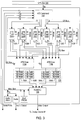
- the 3-D graphics accelerator 112 is principally comprised of a command block 142, a set of floating-point processors 152A - 152F, a set of draw processors 172A and 172B, a frame buffer 100 comprised of 3DRAM, and a random access memory/digital-to-analog converter (RAMDAC) 196.
- a command block 142 a set of floating-point processors 152A - 152F
- draw processors 172A and 172B a set of draw processors 172A and 172B
- frame buffer 100 comprised of 3DRAM
- RAMDAC random access memory/digital-to-analog converter
- the 3-D graphics accelerator 112 includes command block 142 which interfaces to the host bus 104.
- the command block 142 interfaces the graphics accelerator 112 to the host bus 104 and controls the transfer of data between other blocks or chips in the graphics accelerator 112.
- the command block 142 also pre-processes triangle and vector data and performs geometry data decompression when necessary.
- the command block 142 interfaces to a plurality of floating point blocks 152.
- the 3-D graphics accelerator 112 preferably includes up to six floating point blocks labeled 152A-152F, as shown.
- the floating point blocks 152A - 152F receive high level drawing commands and generate graphics primitives, such as triangles, lines, etc. for rendering three-dimensional objects on the screen.
- the floating point blocks 152A - 152F perform transformation, clipping, lighting and set-up operations on received geometry data.
- Each of the floating point blocks 152A - 152F connects to a respective memory 153A - 153F.
- the memories 153A - 153F are preferably 32k x 36-bit SRAM and are used for microcode and data storage.
- Each of the floating point blocks 152A-F connects to each of two drawing blocks 172A and 172B.
- the 3-D graphics accelerator 112 preferably includes two draw blocks 172A and 172B, although a greater or lesser number may be used.
- the draw blocks 172A and 172B perform screen space rendering of the various graphics primitives and operate to sequence or fill the completed pixels into the 3DRAM array.
- the draw blocks 172A and 172B also function as 3DRAM control chips for the frame buffer.
- the draw processors 172A and 172B concurrently render an image into the frame buffer 100 according to a draw packet received from one of the floating-point processors 152A - 152F, or according to a direct port packet received from the command processor 142.
- Each of the floating point blocks 152A-F preferably operates to broadcast the same data to the two drawing blocks 172A and 172B.
- the same data is always on both sets of data lines coming from each floating point block 152.
- the floating point block 152A transfers data
- the floating point block 152A transfers the same data over both parts of the FD-bus to the draw processors 172A and 172B.
- Each of the respective drawing blocks 172A and 172B couple to frame buffer 100, wherein frame buffer 100 comprises four banks of 3DRAM memory 192A - B, and 194A - B.
- the draw block 172A couples to the two 3DRAM banks 192A and 192B, and the draw block 172B couples to the two 3DRAM banks 194A and 194B, respectively.
- Each bank comprises three 3DRAM chips, as shown.
- the 3DRAM memories or banks 192A-B and 194A-B collectively form the frame buffer, which is 1280 x 1024 by 96 bits deep.
- the frame buffer stores pixels corresponding to 3-D objects which are rendered by the drawing blocks 172A and 172B.
- Each of the 3DRAM memories 192A-B and 194A-B couple to a RAMDAC (random access memory digital-to-analog converter) 196.
- the RAMDAC 196 comprises a programmable video timing generator and programmable pixel clock synthesizer, along with cross-bar functions, as well as traditional color look-up tables and triple video DAC circuits.
- the RAMDAC in turn couples to the video monitor 84.
- the command block is preferably Implemented as a single chip.
- Each of the "floating point blocks" 152 are preferably Implemented as separate chips. In the preferred embodiment, up to six floating point blocks or chips 152A-F may be included.
- Each of the drawing blocks or processors 172A and 172B also preferably comprise separate chips.
- command block 142 interfaces with host bus 104 to receive graphics commands and data from host CPU 102.
- command block 142 transfers the information describing the primitive to one of floating point processors 152A-F, along with an indication of stereo mode.
- the selected floating point processor 152 performs two series of operations on the received primitive, one for the left eye view and one for the right eye view. Two primitives corresponding to these left and right eye views are conveyed to draw processors 172 for storage in frame buffer 100, which, in one embodiment, may be partitioned in half to accommodate stereo viewing.
- the general operation of floating point processors 152 is described with reference to Figure 4, while the operation of the floating point processors 152 in stereo mode described with reference to Figures 5-7.
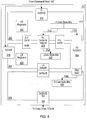
- each of the floating point blocks 152 includes three main functional units or core processors, these being floating point core (F-core) 352, lighting core (L-core) 354, and setup core (S-core) 356.
- the F-core block 352 is coupled to receive data from the CF-bus transferred from the Command block 142.
- the F-core block 352 provides output data to each of the L-core block 354 and the S-core block 356.
- the L-core block 354 also provides data to the S-core block 356.
- the S-core block 356 provides output data to the FD bus.
- the F-core block 352 performs all floating point operations, including geometry transformation, clip testing, face determination, perspective division, and screen space conversion.
- the F-core block 352 also performs clipping when required.
- the F-core block 352 is fully programmable, using a 36-bit micro instruction word stored in a 32k word SRAM 153.
- the L-core block 354 performs substantially all lighting calculations using on-chip RAM-based microcode.
- the L-core block 354 also includes an efficient triple-word design for more efficient lighting calculations. This triple-word design operates with a 48-bit data word comprising 16-bit fixed point values. Thus one instruction can perform the same function on all three color components (RGB) or all three components of a normal (N x , N y , and N z ) in one cycle.
- the math units comprised in the L-core block 354 automatically clamp values to the allowed ranges, thus requiring no additional branches.
- the S-core block performs setup calculations for all primitives. These set-up calculations involve computing the distances in multiple dimensions from one vertex to another and calculating slopes along that edge. For triangles, the slopes of the Z depth, the color, and the UV (for texture) are also computed in the direction of a scan line.
- the slopes of the Z depth, the color, and the UV for texture are also computed in the direction of a scan line.
- each of the floating point blocks 152 includes CF-bus interface logic 362 which couples to the CF-bus.
- Each of the floating point blocks 152 includes FD-bus interface logic 366 which couples to the FD-bus.
- Each floating point block 152 includes a bypass bus or data path 364 which serves as the data transfer path through a respective floating point block 152 for the CD bus. Data which is sent over the CD bus, i.e., which is sent directly to the FD bus, travels on the data transfer bus 364, thus bypassing the floating point logic comprised in the floating point block 152.
- data which is provided to the floating point block 152 can have one of three destinations, these being the F-core block 352, the L-core block 354, or directly out to the FD bus, i.e., a CD bus transfer.
- data which is destined for the F-core block 352 comprises 32-bit words, including 32-bit IEEE floating point numbers and other 32-bit data.
- Data destined for the L-core block 354 comprises 48-bit words comprising three 16-bit fixed point numbers.
- the floating point block 152 includes a plurality of input and output buffers which provide communication between the F-core block 352, L-core block 354, and S-core block 356.
- the floating point block 152 includes a float input buffer (FI buffer) 372 which receives data from the CF-bus which was provided by the command block 142.
- the FI buffer 372 is double buffered and holds 32 32-bit entries in each buffer.
- the first word, word zero, stored in the FI buffer 372 comprises an op code which informs the F-core block 352 which microcode routine to dispatch for the received geometric primitives. Only the header and X, Y and Z coordinates are provided to this buffer when processing geometric primitives.
- the floating point block 152 also includes an F-core to L-core buffer (FL buffer) 374.
- FL buffer 374 is double-buffered and holds 16 16-bit entries in each buffer.
- the F-core block 352 operates to write or combine three F-core words into one L-core word which is provided to the FL buffer 374. From the L-core perspective, each buffer in the FL buffer 374 appears as five 48-bit entries.
- three X, Y, Z coordinates are sent from the F-core block 352 through the FL buffer 374 to the L-core block 354. These three X, Y, Z coordinates are used to compute eye direction.
- the floating point block 152 includes an L-core input buffer (LI buffer) 376 which receives data sent across the CF-bus which was provided from the command block 142 and provides this data to the L-core block 354.
- the LI buffer 376 comprises five buffers, each of which hold seven 48-bit entries. These seven 48-bit entries comprise three vertex normals, three vertex colors and one word with three alpha values.
- the FI buffer 372 and the LI buffer 376 collectively comprise the floating point block input buffer.
- the floating point block 152 also includes an FLL buffer 378, which connects between the F-core block 352 and the L-core block 354.
- the FLL buffer 378 is a FIFO used for transmitting lighting and attenuation factors from the F-core block 352 to the L-core block 354. These attenuation factors comprise three X,Y,Z position values, three attenuation values, three ambient light values, and one attenuation shift word containing three packed values.
- An FLF buffer 380 is also provided between the F-core block 352 and the L-core block 354.
- the FLF buffer is a bi-directional buffer used for communicating data between the F-core block 352 and the L-core block 354 under F-core control.
- An L-core to S-core buffer (LS buffer) 386 is coupled between the L-core block 354 and the S-core block 356.
- the LS buffer 386 is a double buffer with each buffer holding four 48-bit words.
- the floating point block 152 also includes an F-core to S-core buffer (FS buffer) 384 which is used for transferring data from the F-core block 352 to the S-core block 356.
- the FS buffer comprises five buffers which each hold 32 32-bit values. These five buffers are designed to match the pipeline stages of the L-core block 354, these being the two FL buffers, the two LS buffers, plus one primitive which may be stored in the L-core block 354.
- Data transferred from the F-core block 352 through this buffer to the S-core block 356 includes a dispatch code that indicates which microcode procedure to run in the S-core block 356.
- the floating point block 152 includes an S-core output buffer (SO buffer) 158 which is coupled between the S-core block 356 and the FD bus interface 366.
- the SO buffer 158 collects data to be sent across the FD bus to the respective draw processors 172A - 172B.
- the SO buffer 158 is double buffered and holds 32 32-bit words in each buffer.
- the SO buffer 158 holds up to two primitives comprising fixed point data in the order needed by the respective draw processors 172A - 172B.
- S-core block 356 conveys additional status information along with the feed point data to draw processors 172. For example, a status bit is conveyed with each entry indicating whether or not a given primitive is the last of a group of related primitives.
- the SO buffer 158 includes a separate status register which indicates how many words are valid so that the minimum number of cycles are used to transfer the data across the bus.
- the SO buffer 158 comprises the floating point block output buffer 158.
- host CPU 102 calculates view transformation matrices according to the number of desired channels of stereo display. For example, in left/right stereo display, a set of left and right view transformation matrices are generated. These transformation matrices convert the representation of a geometric primitive in model space coordinates to clipping space coordinates (also called eye coordinates in some systems). The view transformation matrices account for the user's vantage point, and are separated into two different sets of matrices because of the binocular disparity caused by left and right eye views.
- command block 142 receives this data, and transfers the matrices to one or more floating point processors 152.
- One subset of the received matrices is stored in F-core block 352; another subset is stored in L-core block 354.
- the matrices stored in L-core block 354 preferably include only the rotational component of the matrices stored in F-core block 352 (translation, scale, and perspective components are preferably not included).
- left and right view transformation matrices are stored separately.
- FIG. 5 a block diagram is shown illustrating portions of the floating point processor which effectuates single-pass stereo.
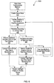
- FIG 6 a flowchart is shown illustrating one embodiment of a method (method 500) for performing single-pass stereo operations in a 3-D graphics accelerator
- the view transformation matrices are stored within F-core block 352.
- the view transformation matrices are stored in one bank of FR registers 402 for the left eye view, and in another bank of FR registers 402 for the right eye view.
- the left eye vector matrix is stored in one group of LR registers 404, while the right eye vector matrix is stored in another group of LR registers 404.
- the same microcode routines perform both left and right eye transformations, with the appropriate transformation matrices selected by hardware by F-core block 352 and L-core block 354.
- the left and right view transformation matrices typically apply to hundreds of successive geometric primitives, and thus do not have to be written to command block 142 prior to each geometric primitive.
- the old copies in F-core block 352 and L-core block 354 may be overwritten.
- host CPU 102 With view transformation matrices stored to one of floating point processors 152, host CPU 102 now enables stereo mode in a step 520. In one embodiment, this is performed by setting a stereo bit in F-core state bits register 410. Once stereo mode is enabled, geometric primitives subsequently transferred from host CPU 102 are processed in stereo mode. Such operation continues until stereo mode is de-activated by clearing the stereo bit in register 410.
- geometry data is transferred from host CPU 102 to graphics accelerator 112, and more specifically, floating point processors 152 in a step 530.
- the geometry data is received by F-core block 352 (in FI buffer 372) and L-core block 354 (in LI buffer 376).
- F-core block 352 In FI buffer 372
- L-core block 354 In LI buffer 376.
- a microcode command is employed to set a bit in F-core state bits register 410 which eye view is currently being performed. (The particular eye view that is transformed first is determined by microcode, and is thus programmable). In one embodiment, the left eye transformation is performed first.
- F-core block 352 interfaces with command block 142 (more particularly, the command-float bus interface) by means of a need/free buffer handshake.
- command block 142 More particularly, the command-float bus interface
- F-core block 352 performs a left eye transformation in step 540 on the geometry data in FI buffer 372 associated with the geometric primitive, employing the view transformation matrices from the left view transformation matrices stored in FR registers 402.
- a "free FI" command is executed by F-core block 352.
- L-core block 354 and S-core block 356 Data corresponding to X, Y, and Z coordinates of the left eye transform is conveyed to L-core block 354 and S-core block 356.
- An instruction recognized by F-core block 352 is employed to additionally transfer stereo mode state bits to L-core block 354 and S-core block 356.
- the transferred stereo mode bits include a stereo mode bit and a "right" bit (which indicates either left or right view processing).
- these stereo mode bits are stored to FL register bank 374, which is preferably a FIFO.
- a "need I" instruction executed by L-core block 354, transfers these bits from FL0 to L-core state bits register 420 when the transformed left view data is transferred from F-core block 352.
- the same stereo mode bits written to FL buffer 374 are also written to FS buffer 384.
- FS buffer 384 is synchronized with the pipeline of data through FL buffer 374, L-core block 354, and LS buffer 386. Lighting computations are performed on the normals, colors, and X, Y, and Z coordinates of the left eye primitive, with the results conveyed through LS buffer 386 to S-core block 356.
- FS buffer 384 is configured such that when the lighting data for the left eye view reaches S-core block 356, the corresponding stereo mode bits are at the "bottom" of FS buffer 384.
- a "need I" instruction executed by S-core block then transfers mode information (including the state of the stereo-related bits) to S-core state bits register 430.
- F-core block 352 frees a location both in FS buffer 384 and FL buffer 374.
- F-core block 352 is now set to operate on a new primitive. Since a stereo mode bit is set in F-core state bits register 410 and the "right" mode in the same register is not set, F-core block 352 again dispatches to the execute stage of its pipeline from location FI0, which is the bottom of FIFO 372. The dispatch to the execute stage toggles the right mode bit to indicate processing is now proceeding in step 560 according to the right eye view transformation matrices.
- the same microcode routine is executed for the left eye view transformation, saving space in SRAM 153. Since the right mode bit is now set, however, the registers utilized for the transformation are automatically mapped to a different group of registers within FR registers 402 than are used in the left eye transformation.
- the X, Y, and Z data corresponding to the right eye view transformation is conveyed to L-core block 354 and S-core block 356 in step 580 for additional graphics operations.
- the "free FI” command is executed by F-core block 352. This time, however, a location in FI buffer 372 is freed in step 600, allowing more data to be received from command block 142.
- a "last output” command causes a header bit to be sent to S-core block 356 indicating the primitive is the last of the stereo pair.
- a "free FS" command causes the right mode bit to toggle back to represent left view transformation, in preparation for receiving the next stereo mode primitive.
- L-core block 354 transfers header data from FL0 register in FL buffer 374 to L-core state bits register 420.
- This header information corresponds to primitive data upon which lighting computations are currently being performed on data in FL buffer 374 and LI buffer 376.
- the lighting calculations for a given primitive are first performed according to the left eye vector matrix.
- a "free LI" command is performed.
- the "free LI" command does not free a location in LI buffer 376 when the right mode bit indicates left view processing and stereo mode is enabled. Instead, the "free LI" command acts like a no-op.
- an L-core command is executed which causes L-core block 354 to dispatch the same microcode routine to operate on the same LI buffer 376 data, only this tune using the right eye vector matrix. Additionally, a new value of the right mode bit which indicates right view processing comes to L-core block 354 from F-core block 352 via FL buffer 374, and is stored in L-core state bits register 420.
- Standard setup calculations are performed by S-core block 356 on both left and right eye primitives conveyed from L-core block 354. These primitives are conveyed to the rendering unit (i.e., draw processors 172A-B) in step 570 (for the left eye data) and step 590 (for right eye data), along with a header value indicating which eye view is represented. Throughout the rasterization process, this left/right header value remains with the primitive until final pixel processing.
- the frame buffer 100 logic writes each pixel to either the left or right stereo buffer depending in accordance with the header value. (When stereo mode is enabled, half of frame buffer 100 is dedicated to storing left eye images, with the other half dedicated to storing right eye images. If stereo mode is not enabled, the frame buffer 100 logic writes each pixel to both buffers).
- draw processors 172 and frame buffer 100 are first initialized to operate in stereo mode before stereo pairs may be rendered on display device 84 in step 610.
- FIG. 6 depicts an alternative embodiment, method 600.
- method 600 which includes the same steps as method 500
- the left eye transformations are completed before processing of the right eye view.
- steps 540, 550, and 570 are completed before steps 560, 580, and 590.
- the input buffer is freed in step 600 after right eye processing is finished, and both images are rendered in the final step 610. It is noted that method 600 is the preferred embodiment of the present invention.
Abstract
Description
Claims (23)
- A method for rendering a geometric primitive in a stereo format in a graphics system, the method comprising:receiving the geometric primitive;rendering the geometric primitive according to a first view;rendering the geometric primitive according to a second view;
wherein said rendering the geometric primitive according to said first view and said rendering the geometric primitive according to said second view operate to render the geometric primitive in the stereo format. - The method of claim 1, wherein said geometric primitive is received in a non-stereo format.
- The method of claim 1 or claim 2, wherein the geometric primitive is only received once by the graphics system.
- The method of any preceding claim, further comprising:storing the geometric primitive in a buffer after said receiving;
wherein said rendering the geometric primitive according to said first view and said rendering the geometric primitive according to said second view each include accessing the geometric primitive from said buffer. - The method of any preceding claim, wherein said geometric primitive comprises a portion of an object, wherein said object comprises a plurality of geometric primitives;
wherein said receiving the geometric primitive, said rendering the geometric primitive according to said first view, and said rendering the geometric primitive according to said second view are repeated for each of said plurality of geometric primitives to render said object in stereo format to a viewer. - The method of any preceding claim, wherein said rendering the geometric primitive according to said first view includes transforming said geometric primitive using a first plurality of view transformation matrices, wherein said first plurality of view transformation matrices corresponding to a first eye of a viewer;
wherein said rendering the geometric primitive according to said second view includes transforming said geometric primitive using a second plurality of view transformation matrices, wherein said second plurality of view transformation matrices corresponding to a second eye of a viewer. - The method of claim 6, wherein said transforming said geometric primitive using said first plurality of view transformation matrices produces a first transformed geometric primitive, wherein said rendering the geometric primitive according to said first view comprises rendering the first transformed geometric primitive;
wherein said transforming said geometric primitive using said second plurality of view transformation matrices produces a second transformed geometric primitive, wherein said rendering the geometric primitive according to said second view comprises rendering the second transformed geometric primitive. - The method of claim 7, wherein said first transformed geometric primitive is a first element of a stereo pair, and wherein said second transformed geometric primitive is a second element of the stereo pair;
wherein said rendering the geometric primitive according to said first view and said rendering the geometric primitive according to said second view operates to render said stereo pair on a display screen, wherein said rendered stereo pair effectuates a stereo mode to a viewer. - The method of claim 6, further comprising:performing additional graphics operations on said first transformed geometric primitive during said transforming said geometric primitive using said second plurality of view transformation matrices.
- The method of claim 6, wherein said first plurality of view transformation matrices are stored in a first memory area;
wherein said second plurality of view transformation matrices are stored in a second memory area;the method further comprising:maintaining a pointer which points to either said first plurality of view transformation matrices in said first memory area or said second plurality of view transformation matrices in said second memory area, wherein said pointer points to said first plurality of view transformation matrices prior to said transforming said geometric primitive using said first plurality of view transformation matrices, and wherein said pointer is adjusted to point to said second plurality of view transformation matrices prior to said transforming said geometric primitive using said second plurality of view transformation matrices. - The method of any preceding claim, further comprising:enabling a stereo mode prior to said rendering.
- A method according to any preceding claim for rendering a geometric primitive in a stereo format in a graphics system, the method comprising:receiving the geometric primitive and storing the geometric primitive in a buffer;transforming said geometric primitive using a first plurality of view transformation matrices, wherein said first plurality of view transformation matrices correspond to a first eye of a viewer, wherein said transforming produces a first transformed geometric primitive, wherein said first transformed geometric primitive is a first element of a stereo pair;transforming said geometric primitive using a second plurality- of view transformation matrices, wherein said second plurality of view transformation matrices correspond to a second eye of a viewer, wherein said transforming said geometric primitive using said second plurality of view transformation matrices produces a second transformed geometric primitive, wherein said second transformed geometric primitive is a second element of said stereo pair;
- The method of claim 12, further comprising:
wherein said transforming said geometric primitive using said first plurality of view transformation matrices and said transforming said geometric primitive using said second plurality of view transformation matrices each include accessing the geometric primitive from said buffer. - A graphics subsystem configured to render a received geometric primitive in a stereo format, comprising:a buffer for storing a received geometric primitive to be rendered in the stereo format;a rendering unit coupled to the buffer which is operable to access the received geometric primitive from said buffer; wherein the rendering unit is configured to render the received geometric primitive according to a first view and render the received geometric primitive according to a second view; wherein the rendering unit operates to render the received geometric primitive in the stereo format.
- The graphics subsystem of claim 14, wherein the graphics subsystem receives said received geometric primitive in a non-stereo format.
- The graphics subsystem of claim 14 or claim 15, wherein the graphics subsystem receives said received geometric primitive only once.
- The graphics subsystem of any one of claims 14 to 16, wherein said geometric primitive comprises a portion of an object, wherein said object comprises a plurality of geometric primitives;
wherein the buffer is operable to receive and store said plurality of geometric primitives;
wherein said rendering unit is operable to access each of said plurality of geometric primitives from said buffer; wherein the rendering unit is configured to render each of said plurality of geometric primitives according to said first view and render each of said plurality of geometric primitives according to said second view to render said object in stereo format to a viewer. - The graphics subsystem of any one of claims 14 to 17, wherein the graphics subsystem further includes:memory for storing left view transformation matrices and right view transformation matrices; anda transformation unit coupled to the memory and to the buffer which is configured to generate a first transformed geometric primitive in response to said received geometric primitive and said left view transformation matrices, and wherein said transformation unit is further configured to generate a second transformed geometric primitive in response to said received geometric primitive and said right view transformation matrices,
wherein said rendering unit operates to render said first transformed geometric primitive and said second transformed geometric primitive on a display screen. - The graphics subsystem of claim 18, wherein said first transformed geometric primitive is a first element of a stereo pair, and wherein said second transformed geometric primitive is a second element of the stereo pair;
wherein the rendering unit operates to render said stereo pair on a display screen, wherein said rendered stereo pair effectuates a stereo mode to a viewer. - The graphics subsystem of claim 18 or claim 19, wherein said received geometric primitive comprises a portion of an object, and wherein said object comprises a plurality of geometric primitives, and wherein said computer system is further configured to render stereo pairs corresponding to each of said plurality of geometric primitives, thereby rendering said object in said stereo mode.
- The graphics subsystem of any one of claims 18 to 20, wherein the transformation unit executes a microcode routine which performs transformation of said received geometric primitive according to said left view transformation matrices in response to an indication that a first half of a given stereo pair is being processed;
wherein the transformation unit executes said microcode routine which performs transformation of said received geometric primitive according to said right view transformation matrices in response to an indication that a second half of said given stereo pair is being processed. - The graphics subsystem of any one of claims 18 to 21, wherein the memory further stores additional sets of left view transformation matrices and right view transformation matrices, and wherein the transformation unit is configured to perform additional operations according to said additional sets of left view transformation matrices and right view transformation matrices, wherein the graphics device is configured to generate an additional stereo pair for each of said additional sets of left view transformation matrices and right view transformation matrices, wherein said graphics device is configured to render each said additional stereo pail on said display screen, thereby effectuating multi-channel stereo viewing.
- A computer system configured to render geometric primitives in a stereo format, comprising:a bus for transferring data;a memory coupled to the bus for storing geometric primitives;a graphics subsystem according to any one of claims 14 to 22, coupled to the bus, wherein the memory is operable to transfer geometric primitives on said bus to the graphics device; anda display screen coupled to the graphics device, wherein the graphics device is operable to render objects in stereo mode on the display screen.
Applications Claiming Priority (2)
| Application Number | Priority Date | Filing Date | Title |
|---|---|---|---|
| US879621 | 1992-05-06 | ||
| US08/879,621 US5982375A (en) | 1997-06-20 | 1997-06-20 | Floating point processor for a three-dimensional graphics accelerator which includes single-pass stereo capability |
Publications (2)
| Publication Number | Publication Date |
|---|---|
| EP0893782A2 true EP0893782A2 (en) | 1999-01-27 |
| EP0893782A3 EP0893782A3 (en) | 2000-01-26 |
Family
ID=25374518
Family Applications (1)
| Application Number | Title | Priority Date | Filing Date |
|---|---|---|---|
| EP98304763A Withdrawn EP0893782A3 (en) | 1997-06-20 | 1998-06-17 | Graphics system and method of rendering |
Country Status (3)
| Country | Link |
|---|---|
| US (1) | US5982375A (en) |
| EP (1) | EP0893782A3 (en) |
| JP (1) | JPH1173523A (en) |
Cited By (1)
| Publication number | Priority date | Publication date | Assignee | Title |
|---|---|---|---|---|
| EP1953702A3 (en) * | 2007-01-30 | 2011-06-15 | Kabushiki Kaisha Toshiba | Apparatus and method for generating CG image for 3-D display |
Families Citing this family (24)
| Publication number | Priority date | Publication date | Assignee | Title |
|---|---|---|---|---|
| JP3813343B2 (en) * | 1997-09-09 | 2006-08-23 | 三洋電機株式会社 | 3D modeling equipment |
| US6650327B1 (en) | 1998-06-16 | 2003-11-18 | Silicon Graphics, Inc. | Display system having floating point rasterization and floating point framebuffering |
| US6674440B1 (en) * | 1999-04-05 | 2004-01-06 | 3Dlabs, Inc., Inc. Ltd. | Graphics processor for stereoscopically displaying a graphical image |
| US6559844B1 (en) * | 1999-05-05 | 2003-05-06 | Ati International, Srl | Method and apparatus for generating multiple views using a graphics engine |
| KR100382108B1 (en) * | 2000-06-24 | 2003-05-01 | 학교법인연세대학교 | 3D graphic accelerator and method for processing graphic acceleration using the same |
| WO2002050777A2 (en) * | 2000-12-18 | 2002-06-27 | Alan Sullivan | Rasterization of three-dimensional images |
| GB2409074B (en) * | 2001-03-14 | 2005-08-03 | Micron Technology Inc | Arithmetic pipeline |
| US6924799B2 (en) * | 2002-02-28 | 2005-08-02 | Hewlett-Packard Development Company, L.P. | Method, node, and network for compositing a three-dimensional stereo image from a non-stereo application |
| US20040100489A1 (en) * | 2002-11-26 | 2004-05-27 | Canon Kabushiki Kaisha | Automatic 3-D web content generation |
| EP1727093A1 (en) * | 2003-12-19 | 2006-11-29 | Tdvision Corporation S.A. DE C.V. | 3d videogame system |
| US7872665B2 (en) | 2005-05-13 | 2011-01-18 | Micoy Corporation | Image capture and processing |
| US7656403B2 (en) * | 2005-05-13 | 2010-02-02 | Micoy Corporation | Image processing and display |
| KR100932977B1 (en) * | 2005-07-05 | 2009-12-21 | 삼성모바일디스플레이주식회사 | Stereoscopic video display |
| KR100913173B1 (en) * | 2005-07-05 | 2009-08-19 | 삼성모바일디스플레이주식회사 | 3 dimension graphic processor and autostereoscopic display device using the same |
| US8279221B2 (en) * | 2005-08-05 | 2012-10-02 | Samsung Display Co., Ltd. | 3D graphics processor and autostereoscopic display device using the same |
| US8284204B2 (en) * | 2006-06-30 | 2012-10-09 | Nokia Corporation | Apparatus, method and a computer program product for providing a unified graphics pipeline for stereoscopic rendering |
| US20100079454A1 (en) * | 2008-09-29 | 2010-04-01 | Legakis Justin S | Single Pass Tessellation |
| US20100328428A1 (en) * | 2009-06-26 | 2010-12-30 | Booth Jr Lawrence A | Optimized stereoscopic visualization |
| JP5502436B2 (en) * | 2009-11-27 | 2014-05-28 | パナソニック株式会社 | Video signal processing device |
| US9578299B2 (en) * | 2011-03-14 | 2017-02-21 | Qualcomm Incorporated | Stereoscopic conversion for shader based graphics content |
| US10817587B2 (en) | 2017-02-28 | 2020-10-27 | Texas Instruments Incorporated | Reconfigurable matrix multiplier system and method |
| US10810281B2 (en) | 2017-02-24 | 2020-10-20 | Texas Instruments Incorporated | Outer product multipler system and method |
| US10735023B2 (en) | 2017-02-24 | 2020-08-04 | Texas Instruments Incorporated | Matrix compression accelerator system and method |
| US11086967B2 (en) * | 2017-03-01 | 2021-08-10 | Texas Instruments Incorporated | Implementing fundamental computational primitives using a matrix multiplication accelerator (MMA) |
Citations (4)
| Publication number | Priority date | Publication date | Assignee | Title |
|---|---|---|---|---|
| US4896210A (en) * | 1987-11-16 | 1990-01-23 | Brokenshire Daniel A | Stereoscopic graphics display terminal with image data processing |
| US5493595A (en) * | 1982-02-24 | 1996-02-20 | Schoolman Scientific Corp. | Stereoscopically displayed three dimensional medical imaging |
| US5523886A (en) * | 1994-01-04 | 1996-06-04 | Sega Of America, Inc. | Stereoscopic/monoscopic video display system |
| GB2308284A (en) * | 1995-11-14 | 1997-06-18 | Mitsubishi Electric Corp | Graphic display unit |
Family Cites Families (5)
| Publication number | Priority date | Publication date | Assignee | Title |
|---|---|---|---|---|
| JPH0669448B2 (en) * | 1989-10-09 | 1994-09-07 | 株式会社東芝 | X-ray image acquisition display method and apparatus for stereoscopic observation |
| US5049987A (en) * | 1989-10-11 | 1991-09-17 | Reuben Hoppenstein | Method and apparatus for creating three-dimensional television or other multi-dimensional images |
| CA2040273C (en) * | 1990-04-13 | 1995-07-18 | Kazu Horiuchi | Image displaying system |
| US5613048A (en) * | 1993-08-03 | 1997-03-18 | Apple Computer, Inc. | Three-dimensional image synthesis using view interpolation |
| JP3311830B2 (en) * | 1993-09-20 | 2002-08-05 | 株式会社東芝 | 3D video creation device |
-
1997
- 1997-06-20 US US08/879,621 patent/US5982375A/en not_active Expired - Lifetime
-
1998
- 1998-06-17 EP EP98304763A patent/EP0893782A3/en not_active Withdrawn
- 1998-06-19 JP JP10172697A patent/JPH1173523A/en active Pending
Patent Citations (4)
| Publication number | Priority date | Publication date | Assignee | Title |
|---|---|---|---|---|
| US5493595A (en) * | 1982-02-24 | 1996-02-20 | Schoolman Scientific Corp. | Stereoscopically displayed three dimensional medical imaging |
| US4896210A (en) * | 1987-11-16 | 1990-01-23 | Brokenshire Daniel A | Stereoscopic graphics display terminal with image data processing |
| US5523886A (en) * | 1994-01-04 | 1996-06-04 | Sega Of America, Inc. | Stereoscopic/monoscopic video display system |
| GB2308284A (en) * | 1995-11-14 | 1997-06-18 | Mitsubishi Electric Corp | Graphic display unit |
Non-Patent Citations (1)
| Title |
|---|
| HIBBARD E: "ON THE THEORY AND APPLICATION OF STEREOGRAPHICS IN SCIENTIFIC VISUALIZATION" PROCEEDINGS OF THE EUROPEAN COMPUTER GRAPHICS CONFERENCE AND EXHIBITION,NL,AMSTERDAM, NORTH HOLLAND, vol. CONF. 12, page 1-21 XP000243006 * |
Cited By (1)
| Publication number | Priority date | Publication date | Assignee | Title |
|---|---|---|---|---|
| EP1953702A3 (en) * | 2007-01-30 | 2011-06-15 | Kabushiki Kaisha Toshiba | Apparatus and method for generating CG image for 3-D display |
Also Published As
| Publication number | Publication date |
|---|---|
| JPH1173523A (en) | 1999-03-16 |
| EP0893782A3 (en) | 2000-01-26 |
| US5982375A (en) | 1999-11-09 |
Similar Documents
| Publication | Publication Date | Title |
|---|---|---|
| US5982375A (en) | Floating point processor for a three-dimensional graphics accelerator which includes single-pass stereo capability | |
| US6141013A (en) | Rapid computation of local eye vectors in a fixed point lighting unit | |
| US6169554B1 (en) | Clip testing unit for a three-dimensional graphics accelerator | |
| US5649173A (en) | Hardware architecture for image generation and manipulation | |
| US10497173B2 (en) | Apparatus and method for hierarchical adaptive tessellation | |
| US7737982B2 (en) | Method and system for minimizing an amount of data needed to test data against subarea boundaries in spatially composited digital video | |
| US6628277B1 (en) | Decompression of three-dimensional graphics data using mesh buffer references to reduce redundancy of processing | |
| US6259460B1 (en) | Method for efficient handling of texture cache misses by recirculation | |
| US7522171B1 (en) | On-the-fly reordering of 32-bit per component texture images in a multi-cycle data transfer | |
| US7081895B2 (en) | Systems and methods of multi-pass data processing | |
| US6459429B1 (en) | Segmenting compressed graphics data for parallel decompression and rendering | |
| JPH05282458A (en) | Plural extensible image buffers for graphics system | |
| EP0817117A2 (en) | Command processor for a three-dimensional graphics accelerator which includes geometry decompression capabilities | |
| CN110675480B (en) | Method and apparatus for acquiring sampling position of texture operation | |
| EP0889441B1 (en) | Lighting unit and method for a three-dimensional graphics accelerator | |
| JP2000000018U (en) | A device that renders three-dimensional objects | |
| US20140055465A1 (en) | Method and system for coordinated data execution using a primary graphics processor and a secondary graphics processor | |
| CN111667542B (en) | Decompression technique for processing compressed data suitable for artificial neural network | |
| JPH11195133A (en) | Graphics accelerator with shift counter generator processing potential fixed point numeral figure overflow | |
| US5847717A (en) | Data synchronization between a plurality of asynchronous data renderers | |
| WO2018063579A1 (en) | Hybrid stereo rendering for depth extension in dynamic light field displays | |
| EP1255227A1 (en) | Vertices index processor | |
| US7609274B2 (en) | System, method, and computer program product for general environment mapping | |
| US6756989B1 (en) | Method, system, and computer program product for filtering a texture applied to a surface of a computer generated object | |
| CN113393564B (en) | Pool-based spatio-temporal importance resampling using global illumination data structures |
Legal Events
| Date | Code | Title | Description |
|---|---|---|---|
| PUAI | Public reference made under article 153(3) epc to a published international application that has entered the european phase |
Free format text: ORIGINAL CODE: 0009012 |
|
| AK | Designated contracting states |
Kind code of ref document: A2 Designated state(s): DE FR GB IT NL SE |
|
| AX | Request for extension of the european patent |
Free format text: AL;LT;LV;MK;RO;SI |
|
| PUAL | Search report despatched |
Free format text: ORIGINAL CODE: 0009013 |
|
| AK | Designated contracting states |
Kind code of ref document: A3 Designated state(s): AT BE CH CY DE DK ES FI FR GB GR IE IT LI LU MC NL PT SE |
|
| AX | Request for extension of the european patent |
Free format text: AL;LT;LV;MK;RO;SI |
|
| RIC1 | Information provided on ipc code assigned before grant |
Free format text: 7G 06T 1/20 A, 7G 06T 15/10 B |
|
| 17P | Request for examination filed |
Effective date: 20000707 |
|
| AKX | Designation fees paid |
Free format text: DE FR GB IT NL SE |
|
| 17Q | First examination report despatched |
Effective date: 20030205 |
|
| RAP1 | Party data changed (applicant data changed or rights of an application transferred) |
Owner name: SUN MICROSYSTEMS, INC. |
|
| STAA | Information on the status of an ep patent application or granted ep patent |
Free format text: STATUS: THE APPLICATION IS DEEMED TO BE WITHDRAWN |
|
| 18D | Application deemed to be withdrawn |
Effective date: 20030617 |