EP0893400A1 - Ozone supplying apparatus - Google Patents
Ozone supplying apparatus Download PDFInfo
- Publication number
- EP0893400A1 EP0893400A1 EP98112590A EP98112590A EP0893400A1 EP 0893400 A1 EP0893400 A1 EP 0893400A1 EP 98112590 A EP98112590 A EP 98112590A EP 98112590 A EP98112590 A EP 98112590A EP 0893400 A1 EP0893400 A1 EP 0893400A1
- Authority
- EP
- European Patent Office
- Prior art keywords
- ozone
- adsorption
- temperature
- desorption
- gas
- Prior art date
- Legal status (The legal status is an assumption and is not a legal conclusion. Google has not performed a legal analysis and makes no representation as to the accuracy of the status listed.)
- Granted
Links
Images


Classifications
-
- B—PERFORMING OPERATIONS; TRANSPORTING
- B01—PHYSICAL OR CHEMICAL PROCESSES OR APPARATUS IN GENERAL
- B01D—SEPARATION
- B01D53/00—Separation of gases or vapours; Recovering vapours of volatile solvents from gases; Chemical or biological purification of waste gases, e.g. engine exhaust gases, smoke, fumes, flue gases, aerosols
- B01D53/02—Separation of gases or vapours; Recovering vapours of volatile solvents from gases; Chemical or biological purification of waste gases, e.g. engine exhaust gases, smoke, fumes, flue gases, aerosols by adsorption, e.g. preparative gas chromatography
- B01D53/04—Separation of gases or vapours; Recovering vapours of volatile solvents from gases; Chemical or biological purification of waste gases, e.g. engine exhaust gases, smoke, fumes, flue gases, aerosols by adsorption, e.g. preparative gas chromatography with stationary adsorbents
- B01D53/0407—Constructional details of adsorbing systems
- B01D53/0423—Beds in columns
-
- B—PERFORMING OPERATIONS; TRANSPORTING
- B01—PHYSICAL OR CHEMICAL PROCESSES OR APPARATUS IN GENERAL
- B01D—SEPARATION
- B01D53/00—Separation of gases or vapours; Recovering vapours of volatile solvents from gases; Chemical or biological purification of waste gases, e.g. engine exhaust gases, smoke, fumes, flue gases, aerosols
- B01D53/02—Separation of gases or vapours; Recovering vapours of volatile solvents from gases; Chemical or biological purification of waste gases, e.g. engine exhaust gases, smoke, fumes, flue gases, aerosols by adsorption, e.g. preparative gas chromatography
- B01D53/04—Separation of gases or vapours; Recovering vapours of volatile solvents from gases; Chemical or biological purification of waste gases, e.g. engine exhaust gases, smoke, fumes, flue gases, aerosols by adsorption, e.g. preparative gas chromatography with stationary adsorbents
- B01D53/047—Pressure swing adsorption
- B01D53/053—Pressure swing adsorption with storage or buffer vessel
-
- C—CHEMISTRY; METALLURGY
- C01—INORGANIC CHEMISTRY
- C01B—NON-METALLIC ELEMENTS; COMPOUNDS THEREOF; METALLOIDS OR COMPOUNDS THEREOF NOT COVERED BY SUBCLASS C01C
- C01B13/00—Oxygen; Ozone; Oxides or hydroxides in general
- C01B13/10—Preparation of ozone
-
- B—PERFORMING OPERATIONS; TRANSPORTING
- B01—PHYSICAL OR CHEMICAL PROCESSES OR APPARATUS IN GENERAL
- B01D—SEPARATION
- B01D2253/00—Adsorbents used in seperation treatment of gases and vapours
- B01D2253/10—Inorganic adsorbents
- B01D2253/106—Silica or silicates
-
- B—PERFORMING OPERATIONS; TRANSPORTING
- B01—PHYSICAL OR CHEMICAL PROCESSES OR APPARATUS IN GENERAL
- B01D—SEPARATION
- B01D2256/00—Main component in the product gas stream after treatment
- B01D2256/14—Ozone
-
- B—PERFORMING OPERATIONS; TRANSPORTING
- B01—PHYSICAL OR CHEMICAL PROCESSES OR APPARATUS IN GENERAL
- B01D—SEPARATION
- B01D2257/00—Components to be removed
- B01D2257/10—Single element gases other than halogens
- B01D2257/104—Oxygen
-
- B—PERFORMING OPERATIONS; TRANSPORTING
- B01—PHYSICAL OR CHEMICAL PROCESSES OR APPARATUS IN GENERAL
- B01D—SEPARATION
- B01D2257/00—Components to be removed
- B01D2257/10—Single element gases other than halogens
- B01D2257/106—Ozone
-
- B—PERFORMING OPERATIONS; TRANSPORTING
- B01—PHYSICAL OR CHEMICAL PROCESSES OR APPARATUS IN GENERAL
- B01D—SEPARATION
- B01D2259/00—Type of treatment
- B01D2259/40—Further details for adsorption processes and devices
- B01D2259/406—Further details for adsorption processes and devices using more than four beds
- B01D2259/4068—Further details for adsorption processes and devices using more than four beds using more than ten beds
-
- B—PERFORMING OPERATIONS; TRANSPORTING
- B01—PHYSICAL OR CHEMICAL PROCESSES OR APPARATUS IN GENERAL
- B01D—SEPARATION
- B01D53/00—Separation of gases or vapours; Recovering vapours of volatile solvents from gases; Chemical or biological purification of waste gases, e.g. engine exhaust gases, smoke, fumes, flue gases, aerosols
- B01D53/02—Separation of gases or vapours; Recovering vapours of volatile solvents from gases; Chemical or biological purification of waste gases, e.g. engine exhaust gases, smoke, fumes, flue gases, aerosols by adsorption, e.g. preparative gas chromatography
- B01D53/04—Separation of gases or vapours; Recovering vapours of volatile solvents from gases; Chemical or biological purification of waste gases, e.g. engine exhaust gases, smoke, fumes, flue gases, aerosols by adsorption, e.g. preparative gas chromatography with stationary adsorbents
- B01D53/0407—Constructional details of adsorbing systems
- B01D53/0431—Beds with radial gas flow
Definitions
- the present invention relates to an ozone supplying apparatus. More particularly, it relates to an ozone supplying apparatus for producing and storing ozone by using electricity which is capable of supplying stored ozone continuously or intermittently at specified ratios to an ozone consuming object.
- an intermittent type ozone supplying apparatus for temporarily storing ozone which comprises the following components as shown in Fig. 15: an ozone generator 50, an oxygen supply source 51, a circulating blower 52, an adsorption/desorption tower 53 for temporarily storing generated ozone, a cooling source 54 for cooling the adsorption/desorption tower 53, a heating source 55 for heating the adsorption/desorption tower 53, a water flow ejector 56 for taking ozone out from the adsorption/desorption tower 53 through decompression and suction, and a group of switch valves 57a to 57g.
- the adsorption/desorption tower 53 is of double cylinder type as shown in Fig.
- an inner cylinder 58 is filled with an ozone adsorbent 59 and is further provided with a spiral heat transferring pipe 60 for heating (refer to Japanese Examined Patent Publication No. 64484/1985).
- a cooling piping 61 through which a cooling medium is made to flow is wound around an outer surface of the inner cylinder 58 in a spiral manner.
- an outer cylinder 63 is filled with a heating medium 62.
- Silica gel is generally used as the adsorbent 59, and ethylene glycol or alcohol group as the heating medium 62.
- numeral 53a is an inlet of the heating medium 62 and 53b an outlet of the heating medium 62.
- the circulating blower 52, ozone generator 50 and adsorption/desorption tower 53 constitute, in this order, a single circulating system.
- Oxygen is supplied by the oxygen supply source 51 through an inlet 53c so that the pressure in the circulating system is always a constant pressure. At this time, the pressure is normally maintained at 1.5 kg/cm 2 .
- oxygen is made to flow in the circulating system by the circulating blower 52 while the switch valves 57c and 57d are in an opened condition, a part of the oxygen is converted into ozone through silent discharge to generate ozonized oxygen while passing through the discharge space of the ozone generator 50, and the ozonized oxygen is then transferred to the adsorption/desorption tower 53.
- the adsorbent in the adsorption/desorption tower 53 selectively adsorbs ozone, and the remaining oxygen is returned to the circulating blower 52 through the switch valve 57c. Oxygen which has been consumed as ozone is supplemented through the oxygen supply source 51. At this time, the temperature of the ozone adsorbent is cooled by the cooling source 54 to not more than -30°C . This is because the ozone adsorbing amount of the ozone adsorbent largely varies depending on the temperature. That is, by lowering the temperature, the ozone adsorbing amount increases and by raising the temperature, the ozone adsorbing amount decreases. Therefore, when adsorbing ozone, the adsorbent is cooled, and when desorbing ozone, the temperature of the adsorbent is raised.
- the desorbing operation of ozone is performed.
- operations of the ozone generator 50, the circulating blower 52 and cooling source 54 are terminated and the switch valves 57a to 57d are closed.
- the heating source 55 and water flow ejector 56 start their operations and switch valves 57e to 57g are opened.
- heat of the heating medium 62 which has been injected from the heating source 55 through inlet 53a is applied from both the inner and outer surfaces of the inner cylinder 58 to raise temperature of the adsorbent 59. Then, by decompressing for sucking ozone in the adsorption/desorption tower 53 at one stroke to the outlet 53d through the water flow ejector 56, ozone is made to disperse and dissolve into water in the water flow ejector 56 which is then sent as ozone water to places where ozone is used.
- the achieved pressure in the adsorption/desorption tower 53 is made to be approximately 0.1 kg/cm 2 (absolute pressure).
- a conventional intermittent type ozone supplying apparatus is disadvantaged in that, by increasing the amount of filled silica gel for storing a large quantity of ozone, time required for cooling silica gel is increased so that ozone can not be efficiently stored, and it is also disadvantaged in that, by increasing the number of arranged ozone adsorption/desorption towers, the installation area is increased or the operation of the apparatus becomes complicated. Further, since the heating source and cooling source are separately arranged, the apparatus is made complicated and maintenance of silica gel in the adsorption/desorption towers is made difficult.
- the present invention has been made in view of the above circumstances, and it is an object of the present invention to provide an ozone supplying apparatus which is capable of shortening time required for cooling the ozone adsorbent, capable of efficiently storing ozone, and which can be arranged to be compact.
- An ozone supplying apparatus comprises an ozone generator for generating ozonized oxygen from raw material oxygen, an adsorption/desorption device for adsorbing and storing ozone from ozonized oxygen and desorbing the ozone, and an ozone desorbing means for desorbing the adsorbed and stored ozone for supply, the apparatus being arranged to return oxygen to the ozone generator after desorbing ozone therefrom by the adsorption/desorption device, and to desorb and supply ozone from the adsorption/desorption device, wherein the adsorption/desorption device includes at least one ozone storing portion filled with an adsorbent, and a liquid storing portion for filling a temperature medium to an outer peripheral surface of the ozone storing portion.
- the ozone storing portion might be arranged to be in the liquid storing portion
- the ozone storing portion might be made in a form of a pipe which is either of cylindrical or of conical shape.
- the ozone supplying apparatus might further include an ozonized oxygen channel in which a distance for ozonized oxygen to flow in the ozone storing portion is longer than an average distance between a central point of the ozone storing portion and a surface thereof at the time of adsorbing ozone, and a distance for ozonized oxygen to flow in the ozone storing portion is shorter than the average distance between the central point of the ozone storing portion and the surface thereof.
- An adsorbent to be filled into the ozone storing portion might be of an integrated type corresponding to a shape of the ozone storing portion and is of porous material.
- the adsorption/desorption device might be disposed in a gas charging vessel for charging gas therein and a pressure adjusting means might be provided for adjusting a gas pressure in the gas charging vessel.
- Gas pressure in the gas charging vessel might be made to be vacuum at the time of storing ozone.
- a branching line might be formed in an ozone circulating line provided between the ozone generator and the adsorption/desorption device, and the branching line is connected to a gas aspirating means for aspirating gas in the adsorption/desorption device and a gas storing tank for temporarily storing gas therein.
- An oxygen refining device might be provided between the gas aspirating device and the gas storing tank.
- the ozone supplying apparatus might further include a temperature adjusting device for adjusting temperature in the adsorption/desorption device and a temperature measuring device for measuring a temperature in the adsorption/desorption device.
- the adsorption/desorption device might be heated by the temperature adjusting device after completion of ozone desorption.
- Fig. 1 is a diagram showing an arrangement of an ozone supplying apparatus according to Embodiment 1 of the present invention
- Fig. 2 is a detailed diagram showing an ozone adsorption/desorption device in Fig. 1.
- Such an apparatus comprises, as shown in Figs.
- an ozone generator 1 for generating ozonized oxygen
- an oxygen supply source 2 for supplying oxygen
- a circulating blower 3 for circulating the generated ozone
- a temperature adjusting device 7 for adjusting temperature of a temperature medium 6 to be filled within a liquid storing portion which resides inside of an outer cylinder 5 in the adsorption/desorption device 4
- a water flow ejector 8 which is an ozone desorbing means
- switch valves 9a to 9e switch valves 9a to 9e.
- a plurality of adsorption/desorption tubes 10 as the ozone storing portion are disposed within the outer cylinder 5 of the adsorption/desorption device 4, and the inside of the adsorption/desorption tube 10 is filled with an adsorbent 11.
- the temperature medium for adjusting temperature of the adsorbent 11 flows an outer surface of the adsorption/desorption tube 10. It is preferable to select an adsorbent having a low decomposing rate when it comes into contact with ozone.
- silica gel, activated alumina or porous materials impregnated with fluorocarbon can be employed.
- ethylene glycol or alcohol group might be used as the temperature medium 6.
- numerals 4a to 4d denote an inlet for temperature medium, an outlet for temperature medium, an inlet for ozonized oxygen, and an outlet for ozonized oxygen, respectively.
- Oxygen is supplied by the oxygen supply source 2 so that the pressure in the circulating system is always constant, for example 1.5 kg/cm 2 .
- an excessive increase of pressure in the circulating system results in an increase in consumption of electricity at the time of storage so that it is desirable to maintain a pressure of about 5kg/cm 2 G in maximum.
- the desorbing operation is performed.
- operations of the ozone generator 1 and the circulating blower 3 are terminated and switch valves 9a to 9d are closed.
- the water flow ejector 8 starts its operation and the switch valve 9e is opened.
- the temperature medium 6 is heated by the temperature adjusting device 7 and the temperature medium 6 is applied from the outside of the adsorption/desorption tube 10 to raise the temperature of the adsorbent 11.
- ozone is made to disperse and dissolve into water in the water flow ejector 8 and is supplied as ozone water to places where ozone is used.
- the achieved pressure in the adsorption/desorption tubes 10 by decompression for suction is approximately 0.1 kg/cm 2 (absolute pressure).
- Fig. 3 is a sectional diagram taken along the line I-I of the adsorption/desorption device. As shown in Fig. 3, by providing a plurality of adsorption/desorption tubes 10 filled with adsorbent 11 in the interior of the outer cylinder 5, ozone can be efficiently adsorbed to a small space of the outer cylinder 5.
- the cooling time needs to be set to less than 24 hours in maximum so that it is desirably to set the radius of the adsorption/desorption tubes to not more than 12 cm.
- Fig. 5 is a diagram showing a relationship between the radius of the adsorption/desorption tubes and an occupying area ratio of the adsorbent filling portion in the outer cylinder. It can be understood that the occupying area ratio increases with a decrease in radius when the radius of the adsorption/desorption tube is approximately in the range between 20 cm to 10 cm, and when the radius is smaller than 10cm, the occupying area ratio decreases due to influence of a thickness of the adsorption/desorption tubes. Thus, it is preferable to set the radius of the adsorption/desorption tubes to 5 to 20 cm in view of securing a filling amount of silica gel.
- a preferable range for the radius of the adsorption/desorption tubes is approximately 5 to 10 cm for efficiently storing ozone.
- ozone might also be desorbed by terminating the temperature adjusting device 7 to cease control of temperature for the temperature medium 6 and decompressing for sucking ozone in the adsorption/desorption device 4 by the water flow ejector 8.
- the amount of energy required at the time of desorption can be decreased to obtain an ozone supplying apparatus of power-saving type.
- Embodiment 1 has been explained by taking a case in which the adsorption/desorption tube is of cylindrical shape and in which a plurality of adsorption/desorption tubes 10 are arranged in the outer cylinder, the apparatus might be alternatively arranged as shown in Fig. 6 wherein adsorption/desorption tubes 20 are of conical trapezoid shape of which wide opening sides and narrow opening sides are alternately arranged.
- Fig. 7 is a sectional diagram taken along the line II-II of adsorption/desorption device 21 of the present embodiment.
- a cooled temperature medium 6 is made to pass through an inlet 21a to an outlet 21b at the time of adsorbing ozone and ozonized oxygen is made to flow through inlet 21c to flow into adsorption/desorption tube 20 from a narrow opening side in the bottom portion of the ozone storing device 21, to be released from a wide opening side in the top portion, to flow into the adsorption/desorption tube 20 again through a narrow opening side on the top portion and to be released from an outlet 21d in the bottom portion.
- the adsorbent By performing adsorption in this manner, the adsorbent can be first cooled to its central portion in a proximity of the side of the inlet 21c for the ozonized gas and a cavity speed (a speed at which ozonized gas moves through the adsorption/desorption tube) in the side of the outlet 21d for the ozonized gas can be made slow, whereby ozone can be efficiently adsorbed.
- ozone might also be desorbed by connecting the adsorption/desorption tubes 20 in a serial manner, similarly to the adsorbing process, or might be alternatively desorbed by taking out ozone from gas aspirating openings in a top portion without connecting them in a series but separating the narrow and wide openings (and closing the narrow openings) and then taking out ozone from an aspirating opening in the bottom portion.
- an amount of re-adsorbing ozone can be decreased. It should be noted that the arrangement in which adsorption/desorption tubes are not connected in a serial manner results in a further decrease in a contact amount of the adsorbent and ozone, whereby desorbing effects can be improved.
- Fig. 8 is a diagram showing an ozone adsorption/desorption device 30 which is a major part of the ozone supplying apparatus according to Embodiment 3 of the present invention.
- numeral 31 denotes an adsorbent for temporarily storing generated ozone
- 32 an inner cylinder for storing the adsorbent 31
- 33 a temperature medium for adjusting temperature of the ozone adsorbent 31 included in the inner cylinder 32
- 34 an outer cylinder through which the temperature medium 33 flows
- 35 an ozone channel tube through which ozonized oxygen flows at the time of desorbing ozone
- 36 a channel cover which is attached closely to the outer surface of the ozone channel tube 35, 37 a motor for rotating the ozone channel tube 35, and 38 a mesh for supporting the adsorbent.
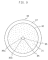
- Fig. 9 is a sectional diagram taken along the line III-III of the adsorption/desorption device 30. As shown in Fig. 9, when performing desorption, an opening 36a provided in the channel cover 36 and an opening 35a provided in the ozone channel tube 35 are made to coincide by rotating the ozone channel tube 35 by the motor 37, and ozonized oxygen is made to flow to the opening 35a of the ozone channel tube 35 located in the central portion of the inner cylinder 32.
- Ozonized oxygen which has reached the adsorption/desorption device 30 is introduced from the inlet 30c in the bottom surface side into the adsorption/desorption device 30.
- Ozonized oxygen which has been supplied to the interior of the adsorption/desorption device 30 is supplied to the adsorbent 31 by passing through a mesh 38.
- the opening 35a of the ozone channel tube 35 is closed by the channel cover 36 so that ozonized oxygen can be prevented from being supplied to the adsorbent 31 via the opening 35a of the ozone channel tube 35.
- Oxygen gas which has not been adsorbed is discharged from outlet 30d in the top portion and returned, as shown in Fig.
- the desorbing operation is performed.
- operations of the ozone generator 1, circulating blower 3 and temperature adjusting device 7 are terminated and switch valves 9a to 9d are closed.
- the ozone channel tube 35 is then rotated by the motor 37 and the opening 35a of the ozone channel tube 35 which has been closed by the channel cover 36 is made to be open. Thereafter, the water flow ejector 8 starts operation and switch valve 9e is opened.
- ozone which has been adsorbed at the adsorbent 31 in the inner cylinder 32 flows into the ozone channel tube 35 through the opening 35a thereof by the coincidence of the opening 36a provided in the channel cover 36 and the opening 35a of the ozone channel tube 35, and ozone is made to disperse and dissolve into water in the water flow ejector 8 and is supplied as ozone water to places where ozone is used.
- the achieved pressure in the inner cylinder 32 by the decompression for suction is approximately 0.1 kg/cm 2 (absolute pressure).
- the desorbing process might alternatively be started when ozone of a specified density starts to leak out from the adsorption/desorption device 30. Further, in order to enable easy desorption of ozone adsorbed at the adsorbent 31, desorption of ozone might be performed by heating the temperature medium 33 through the temperature adjusting device 7. It is also possible to employ a gas ejector or an aspiration pump instead of the water flow ejector 8.
- the adsorption/desorption device 30 is generally of columnar shape of which height is exceeding its diameter in order to make the installation area thereof as small as possible.
- ozonized oxygen is made to flow in a height direction at the time of adsorption and in a radial direction at the time of desorption, whereby the time of ozone adsorbing and breaking-through (leaking out) can be delayed in the adsorbing process and the amount of desorbed ozone which is re-adsorbed to the adsorbent can be decreased in the desorbing process.
- ozone can be efficiently adsorbed and desorbed.
- Fig. 10 is a diagram showing an ozone adsorption/desorption device 40 which is a major part of the ozone supplying apparatus according to Embodiment 4 of the present invention.
- 41 denotes an adsorbent for temporarily adsorbing generated ozone
- 42 adsorption/desorption tubes for storing the adsorbent 41
- 43 a temperature medium for adjusting the temperature of the ozone adsorbent 41 included in the adsorption/desorption tubes 42
- 44 an outer cylinder through which the temperature medium 43 flows
- 45 an adiabatic vessel which is a charging vessel for charging gas and preventing heat diffusion from the outer cylinder 41 through which the temperature medium flows
- 46 an adjuster which is a pressure adjusting means for adjusting a gas pressure in the adiabatic vessel 45.
- the adsorption/desorption device 40 of this embodiment is provided in the adiabatic vessel 45.
- Ozonized oxygen which has reached the adsorption/desorption device 40 is introduced into the adsorption/desorption device 40 from an inlet 40c on the bottom face side.
- the pressure in the adiabatic vessel 45 is made to be in a vacuum state (not more than 10 -4 torr) by the pressure adjuster 46 and the temperature of the adsorbent 41 in the adsorption/desorption tubes 42 is adjusted by the temperature medium 43 of which temperature is adjusted by the temperature adjusting device 7.
- ozonized oxygen which is supplied into the adsorption/desorption device 40 is supplied to the adsorbent 41 in the adsorption/desorption tubes 42.
- Oxygen gas which has not been adsorbed is discharged from outlet 40d in the top portion and is returned to the circulating blower 3 via the switch valve 9c. Oxygen which has been consumed as ozone is supplemented by the oxygen supply source 2.
- the desorbing operation is performed.
- operations of the ozone generator 1, circulating blower 3 and temperature adjusting device 7 are terminated and switch valves 9a to 9d are closed.
- the pressure in the adiabatic vessel 45 is raised by the pressure adjuster 46. While it is desirable to make the pressure in the adiabatic vessel 45 as high as possible at this time, the pressure in the adiabatic vessel 45 is set to 2 to 3 kg/cm 2 because manufacturing costs will increase when its pressure-proof performance is improved.
- ozone in the adsorption/desorption device 40 is decompressed for suction by the ejector 8 and ozone is made to disperse and dissolve into water in the water flow ejector 8 and is supplied as ozone water to places where ozone is used.
- the achieved pressure in the adsorption/desorption tube 42 by the decompression for suction is approximately 0.1 kg/cm 2 (absolute pressure).
- the heat dispersing amount from the outer cylinder 44 can be decreased to efficiently perform cooling of the adsorbent 41 at the time of adsorption while the heat dispersing amount from the outer cylinder 44 can be promoted to efficiently raise the temperature of the adsorbent 41 at the time of desorption, whereby an ozone supplying apparatus of energy-saving type compared to conventional apparatuses can be obtained.
- Fig. 11 is a diagram showing an ozone supplying apparatus according to Embodiment 5 of the present invention
- numerals which are identical with those of the previous Embodiment 1 indicate identical or equivalent portions and explanations thereof will be omitted.
- the apparatus is provided with a temperature adjusting device 51 for adjusting temperature in the adsorption/desorption device 4 and a temperature sensor 52 which is either a contact type or non-contact type temperature measuring device for measuring a temperature of the adsorbent in the adsorption/desorption device 4.
- a temperature sensor 52 which is either a contact type or non-contact type temperature measuring device for measuring a temperature of the adsorbent in the adsorption/desorption device 4.
- the temperature sensor 52 is disposed in a proximity of the inlet 4a for the temperature medium and is capable of measuring temperature of the absorbent 11 which is disposed in the proximity of the wall surface in the adsorption/desorption tube 10.
- the temperature controlling method at the time of adsorption will first be explained. At the time of adsorbing ozone, it is important to decrease temperature of the adsorbent in a short time.
- the set temperature for the temperature medium is set to a temperature which is lower than a target temperature which the adsorbent is to reach at last, that is, when the target temperature is -60°C, the set temperature is set to -70°C which is lower than -60°C.
- This temperature medium is then supplied to the adsorption/desorption device 4 from the inlet 4a for the temperature medium.
- the temperature of the adsorbent in the proximity of the wall surface is observed by the temperature sensor 52, and when this temperature has reached the set temperature, the temperature of the temperature medium is set to approach the target temperature by units of several °C. By repeating this operation, the temperature of the temperature medium is set to be the target temperature at last. By performing such control of temperature, the temperature of the adsorbent can be cooled in a short time.
- Fig. 12 is a diagram showing a relationship between a cooling time and a cooling temperature of the adsorbent, which is, for instance, silica gel, existing in the central portion of the adsorption/desorption tube having a radius of 12 cm.
- adsorbent which is, for instance, silica gel
- Ts3 -72°C ⁇ -66°C ⁇ -60°C
- Ts4 -78°C ⁇ -72°C ⁇ -66°C ⁇ -60°C
- the shorter the cooling temperature could be made.
- the temperature adjusting device 7 it is not desirable to operate the temperature adjusting device 7 with COP being not more than 0.5 in view of decreasing the amount of energy consumed in the temperature adjusting device 7.
- the set temperature for the temperature medium is set to a temperature which is lower than a target temperature which the adsorbent is to reach at last, that is, when the target temperature is -60°C, the set temperature is set to -70°C which is lower than -60°C
- This temperature medium is then supplied to the adsorption/desorption device 4 from the inlet 4a for the temperature medium.
- the temperature of the adsorbent in the proximity of the wall surface is observed by the temperature sensor 52, and when this temperature has reached the set temperature, the temperature of the temperature medium is set to approach the target temperature by units of several °C. By repeating this operation, the temperature of the temperature medium is set to be the target temperature at last.
- the temperature of the adsorbent can be heated in a short time and abrupt desorption of ozone can be prevented.
- the location for installing the temperature sensor 52 will be explained.
- This embodiment is so arranged, both in adsorbing process and desorbing process, as to make the temperature of the adsorbent reach the target temperature in a short time and in an energy-saving way as much as possible. Therefore, since making the temperature of the adsorbent lower than the target temperature causes problems in terms of energy at the time of adsorption, the temperature sensor 52 is preferably disposed at a location at which the temperature of the adsorbent reaches a temperature of the temperature medium at the shortest time.
- the temperature sensor 52 it is preferable to dispose the temperature sensor 52 in a proximity of the inlet 4a for the temperature medium of the adsorption/desorption device and in a periphery portion of an adsorption/desorption tube which is closest to the temperature medium. Further, since the temperature of the adsorbent needs to be raised as rapidly as possible at the time of desorption, the temperature sensor 52 is preferably disposed at a location at which the temperature of the adsorbent reaches a temperature of the temperature medium at the shortest time.
- the temperature sensor 52 in a proximity of the inlet 4a for the temperature medium of the adsorption/desorption device and in a peripheral portion of an adsorption/desorption tube which is closest to the temperature medium, similarly to the time of performing adsorption.
- the temperature sensor 52 needs to be provided only at a representative adsorption/desorption tube 10.
- temperature sensors 52 might be provided to a plurality of adsorption/desorption tubes 10 for multiple control. While this arrangement has an effect of enabling precise temperature control of the adsorption/desorption tube 10, the increase in number of temperature sensors 52 and complicated control system result in a higher cost of the apparatus.
- Fig. 14 is a diagram showing an ozone supplying apparatus according to Embodiment 6 of the present invention.
- reference numerals which are identical with those of the previous Embodiment 1 indicate identical or equivalent portions and explanations thereof will be omitted.
- Numeral 61 denotes a gas aspirating means for aspirating gas from an ozone circulating line L1, 62 an oxygen refining device for refining oxygen gas to be of high purity, 63 a gas storing tank for temporarily storing refined oxygen gas therein, and 64a and 64b switch valves of a main loop (ozone circulating line L1) and a sub loop (branching line L2), respectively.
- switch valves 9e and 64a are closed. Thereafter, the switch valve 9d is opened and the switch valve 64a is switched on.
- the temperature of temperature medium is further raised by the temperature adjusting device 7 to be more than temperature at the time of ozone desorption. With this arrangement, the temperature of adsorbent is raised and substances which remain adsorbed at the adsorbent start separation.
- the gas aspirating means 61 starts operation and remaining substances in the adsorption/desorption device 4 are aspirated to the oxygen refining device 62. Oxygen gas which has been refined by the oxygen refining device 62 is then sent to the gas storing tank 63. Oxygen which is stored in the gas storing tank 63 is used when the adsorbing operation is again performed.
- Embodiments 1 to 6 have been explained by taking a case in which the adsorbent is of grain type, integrated type silica gel corresponding to the internal shape of the adsorption/desorption tubes 10, conical adsorption/desorption tubes 20 or inner cylinder 32 might also be used.
- Sodium borosilicate type glass is molded to be of a shape of the interior of the adsorption/desorption tubes 10 and is gradually cooled at a temperature which is not more than a melting point. After treating with strong acid, a boron oxide phase thereof dissolves so that an integrated type and porous silica gel (porous body) can be manufactured.
- the adsorbent can be made integrated without decreasing adsorption efficiency of ozone, and exchange of adsorbent can be easily performed.
- the adsorption/desorption device includes at least one ozone storing portion filled with an adsorbent, and a liquid storing portion for filling a temperature medium to an outer peripheral surface of the ozone storing portion, whereby the ozone adsorbing portion can be cooled in a short time, ozone can be effectively stored and the adsorption/desorption device can be made compact.
- the ozone adsorbing portion When the ozone storing portion is arranged to be in the liquid storing portion, the ozone adsorbing portion can be cooled in a short time, ozone can be effectively stored and the adsorption/desorption device can be made compact.
- the ozone storing portion is made in a form of a pipe which is either of cylindrical or of conical shape, the ozone adsorbing portion can be cooled in a short time, ozone can be effectively stored and the adsorption/desorption device can be made compact.
- the apparatus further includes an ozonized oxygen channel in which a distance for ozonized oxygen to flow in the ozone storing portion is longer than an average distance between a central point of the ozone storing portion and a surface thereof at the time of adsorbing ozone, and a distance for ozonized oxygen to flow in the ozone storing portion is shorter than the average distance between the central point of the ozone storing portion and the surface thereof, ozone can be effectively stored and the loss amount of ozone at the time of adsorption and desorption can be decreased.
- the adsorbent to be filled into the ozone storing portion is of an integrated type corresponding to a shape of the ozone storing portion and is of porous material, maintenance such as exchange of ozone adsorbent can be easily performed.
- the adsorption/desorption device When the adsorption/desorption device is disposed in a gas charging vessel for charging gas therein and a pressure adjusting means is provided for adjusting a gas pressure in the gas inclusion vessel, the amount of electricity consumed at the time of storing ozone can be decreased, desorption of ozone can be rapidly performed and arrangement of the ozone storing portion can be simplified.
- the amount of electricity consumed at the time of storing ozone can be decreased.
- a branching line is formed in an ozone circulating line provided between the ozone generator and the adsorption/desorption device, and the branching line is connected to a gas aspirating means for aspirating gas in the adsorption/desorption device and a gas storing tank for temporarily storing gas therein, substances which badly affect ozone at the time of desorption can be removed and ozone can be efficiently stored. Further, oxygen remaining at the adsorbent can be reused and the amount of used oxygen is decreased.
- oxygen refining device When an oxygen refining device is provided between the gas aspirating device and the gas storing tank, oxygen remaining at the adsorbent can be reused and the amount of used oxygen is decreased.
- the apparatus further includes a temperature adjusting device for adjusting temperature in the adsorption/desorption device and a temperature measuring device for measuring a temperature in the adsorption/desorption device, desorption of ozone can be performed in a short time and the amount of electricity consumed at the time of adsorbing and storing ozone can be decreased.
Abstract
Description
Claims (11)
- An ozone supplying apparatus comprisingthe apparatus being arranged to return oxygen to the ozone generator (1) after desorbing ozone therefrom by the adsorption/desorption device (4), and to desorb and supply ozone from the adsorption/desorption device (4), wherein the adsorption/desorption device (4) includes at least one ozone storing portion (10, 20, 32, 42) filled with an adsorbent (11, 31, 41), and a liquid storing portion (5, 34, 44) for filling a temperature medium (6, 33, 43) to an outer peripheral surface of the ozone storing portion (10, 20, 32, 42).an ozone generator (1) for generating ozonized oxygen from raw material oxygen,an adsorption/desorption device (4) for adsorbing and storing ozone from ozonized oxygen and desorbing the ozone, andozone desorbing means (8) for desorbing the adsorbed and stored ozone for supply,
- The apparatus of claim 1,
wherein the ozone storing portion (10, 20, 32, 42) is arranged to be in the liquid storing portion (5, 34, 44). - The apparatus of any of claims 1 and 2,
wherein the ozone storing portion (10, 20, 32, 42) is made in a form of a pipe which is either of cylindrical shape (10, 32, 42) or of conical shape (20). - The apparatus of any of claims 1 to 3,
wherein the apparatus further includes an ozonized oxygen channel (35) in which a distance for ozonized oxygen to flow in the ozone storing portion (32) is longer than an average distance between a central point of the ozone storing portion (32) and a surface thereof at the time of adsorbing ozone, and a distance for ozonized oxygen to flow in the ozone storing portion (32) is shorter than the average distance between the central point of the ozone storing portion (32) and the surface thereof. - The apparatus of any of claims 1 to 4,
wherein the adsorbent (11, 31, 41) to be filled into the ozone storing portion (10, 20, 32, 42) is of an integrated type corresponding to the shape of the ozone storing portion (10, 20, 32, 42) and is of porous material. - The apparatus of any of claims 1 to 5,
wherein the adsorption/desorption device (4) is disposed in a gas charging vessel (45) for charging gas therein and pressure adjusting means (46) are provided for adjusting the gas pressure in the gas charging vessel (45). - The apparatus of claim 6,
wherein the gas pressure in the gas charging vessel (45) is made to be a vacuum pressure at the time of storing ozone. - The apparatus of any of claims 1 to 7,
wherein a branching line (L2) is formed in an ozone circulating line (L1) provided between the ozone generator (1) and the adsorption/desorption device (4), and the branching line (L2) is connected to gas aspirating means (61) for aspirating gas in the adsorption/desorption device (4) and a gas storing tank (63) for temporarily storing gas therein. - The apparatus of claim 8,
wherein an oxygen refining device (62) is provided between the gas aspirating device (61) and the gas storing tank (63). - The apparatus of any of claims 1 to 9,
wherein the apparatus further includes a temperature adjusting device (51) for adjusting the temperature in the adsorption/desorption device (4) and a temperature measuring device (52) for measuring the temperature in the adsorption/desorption device (4). - The apparatus of claim 10,
wherein the adsorption/desorption device (4) is heated by the temperature adjusting device (51) after completion of ozone desorption.
Priority Applications (1)
| Application Number | Priority Date | Filing Date | Title |
|---|---|---|---|
| EP04002816A EP1419993A3 (en) | 1997-07-24 | 1998-07-07 | Ozone supplying apparatus |
Applications Claiming Priority (3)
| Application Number | Priority Date | Filing Date | Title |
|---|---|---|---|
| JP19843897 | 1997-07-24 | ||
| JP19843897A JP3670451B2 (en) | 1997-07-24 | 1997-07-24 | Ozone supply device |
| JP198438/97 | 1997-07-24 |
Related Child Applications (1)
| Application Number | Title | Priority Date | Filing Date |
|---|---|---|---|
| EP04002816A Division EP1419993A3 (en) | 1997-07-24 | 1998-07-07 | Ozone supplying apparatus |
Publications (2)
| Publication Number | Publication Date |
|---|---|
| EP0893400A1 true EP0893400A1 (en) | 1999-01-27 |
| EP0893400B1 EP0893400B1 (en) | 2004-09-29 |
Family
ID=16391093
Family Applications (2)
| Application Number | Title | Priority Date | Filing Date |
|---|---|---|---|
| EP98112590A Expired - Lifetime EP0893400B1 (en) | 1997-07-24 | 1998-07-07 | Ozone supplying apparatus |
| EP04002816A Withdrawn EP1419993A3 (en) | 1997-07-24 | 1998-07-07 | Ozone supplying apparatus |
Family Applications After (1)
| Application Number | Title | Priority Date | Filing Date |
|---|---|---|---|
| EP04002816A Withdrawn EP1419993A3 (en) | 1997-07-24 | 1998-07-07 | Ozone supplying apparatus |
Country Status (5)
| Country | Link |
|---|---|
| US (2) | US6228331B1 (en) |
| EP (2) | EP0893400B1 (en) |
| JP (1) | JP3670451B2 (en) |
| CA (1) | CA2243062C (en) |
| DE (1) | DE69826577T2 (en) |
Cited By (1)
| Publication number | Priority date | Publication date | Assignee | Title |
|---|---|---|---|---|
| US6530976B2 (en) | 2000-03-02 | 2003-03-11 | The Kansai Electric Power Co., Inc. | Ozone storage method and ozone storage apparatus |
Families Citing this family (7)
| Publication number | Priority date | Publication date | Assignee | Title |
|---|---|---|---|---|
| JP3670451B2 (en) * | 1997-07-24 | 2005-07-13 | 三菱電機株式会社 | Ozone supply device |
| US6376387B2 (en) * | 1999-07-09 | 2002-04-23 | Applied Materials, Inc. | Method of sealing an epitaxial silicon layer on a substrate |
| US7392657B2 (en) * | 2004-06-09 | 2008-07-01 | American Air Liquide, Inc. | Methods of dissolving ozone in a cryogen |
| US7911625B2 (en) * | 2004-10-15 | 2011-03-22 | Fujifilm Dimatrix, Inc. | Printing system software architecture |
| CN101878182B (en) * | 2007-11-30 | 2013-01-09 | 三菱电机株式会社 | Ozone concentrator |
| JP6976893B2 (en) * | 2018-03-29 | 2021-12-08 | 住友精化株式会社 | Gas boosting method and gas booster |
| CN111304633B (en) * | 2020-03-23 | 2022-07-22 | 北京北方华创微电子装备有限公司 | Vapor deposition apparatus and vapor deposition method |
Citations (5)
| Publication number | Priority date | Publication date | Assignee | Title |
|---|---|---|---|---|
| US2872397A (en) * | 1955-01-10 | 1959-02-03 | Union Carbide Corp | Method and apparatus for producing ozone-carrier gas mixture |
| EP0103144A2 (en) * | 1982-08-20 | 1984-03-21 | Messer Griesheim Gmbh | Process for producing ozone |
| US4453953A (en) * | 1981-05-12 | 1984-06-12 | Mitsubishi Denki Kabushiki Kaisha | Intermittent ozone feeding apparatus |
| JPH03103304A (en) * | 1989-09-14 | 1991-04-30 | Ishikawajima Harima Heavy Ind Co Ltd | Method for feeding ozone |
| US5520887A (en) * | 1993-11-22 | 1996-05-28 | Ishikawajima-Harima Heavy Industries Co., Ltd. | Apparatus for generating and condensing ozone |
Family Cites Families (12)
| Publication number | Priority date | Publication date | Assignee | Title |
|---|---|---|---|---|
| JPS523595A (en) | 1975-06-27 | 1977-01-12 | Mitsubishi Electric Corp | Ozonizer with oxygen recycle system |
| JPS592559B2 (en) | 1978-11-02 | 1984-01-19 | 三菱電機株式会社 | Microorganism removal device |
| JPS55158107A (en) | 1979-05-29 | 1980-12-09 | Mitsubishi Electric Corp | Oxygen recycling type ozone generating apparatus |
| US4552659A (en) | 1980-03-04 | 1985-11-12 | Mitsubishi Denki Kabushiki Kaisha | Apparatus for elimination of biofouling |
| JPS6048444B2 (en) * | 1981-06-05 | 1985-10-28 | 三菱電機株式会社 | Intermittent ozone supply device |
| EP0567860B2 (en) * | 1992-04-28 | 2003-01-29 | Mitsubishi Denki Kabushiki Kaisha | System and microorganism removing method |
| CA2186976C (en) * | 1995-02-06 | 2001-09-04 | Hiroshi Sanui | Ozone enriching method |
| JP3980091B2 (en) * | 1996-03-01 | 2007-09-19 | 三菱電機株式会社 | Ozone storage equipment |
| JP3670451B2 (en) * | 1997-07-24 | 2005-07-13 | 三菱電機株式会社 | Ozone supply device |
| JPH1143307A (en) * | 1997-07-24 | 1999-02-16 | Mitsubishi Electric Corp | Apparatus for producing ozone |
| JPH1143309A (en) | 1997-07-24 | 1999-02-16 | Mitsubishi Electric Corp | Apparatus for producing ozone |
| JP4087927B2 (en) | 1997-07-24 | 2008-05-21 | 三菱電機株式会社 | Ozone supply device |
-
1997
- 1997-07-24 JP JP19843897A patent/JP3670451B2/en not_active Expired - Fee Related
-
1998
- 1998-07-07 EP EP98112590A patent/EP0893400B1/en not_active Expired - Lifetime
- 1998-07-07 EP EP04002816A patent/EP1419993A3/en not_active Withdrawn
- 1998-07-07 DE DE69826577T patent/DE69826577T2/en not_active Expired - Lifetime
- 1998-07-08 US US09/111,184 patent/US6228331B1/en not_active Expired - Lifetime
- 1998-07-13 CA CA002243062A patent/CA2243062C/en not_active Expired - Lifetime
-
2000
- 2000-11-28 US US09/722,729 patent/US6495109B1/en not_active Expired - Lifetime
Patent Citations (5)
| Publication number | Priority date | Publication date | Assignee | Title |
|---|---|---|---|---|
| US2872397A (en) * | 1955-01-10 | 1959-02-03 | Union Carbide Corp | Method and apparatus for producing ozone-carrier gas mixture |
| US4453953A (en) * | 1981-05-12 | 1984-06-12 | Mitsubishi Denki Kabushiki Kaisha | Intermittent ozone feeding apparatus |
| EP0103144A2 (en) * | 1982-08-20 | 1984-03-21 | Messer Griesheim Gmbh | Process for producing ozone |
| JPH03103304A (en) * | 1989-09-14 | 1991-04-30 | Ishikawajima Harima Heavy Ind Co Ltd | Method for feeding ozone |
| US5520887A (en) * | 1993-11-22 | 1996-05-28 | Ishikawajima-Harima Heavy Industries Co., Ltd. | Apparatus for generating and condensing ozone |
Non-Patent Citations (2)
| Title |
|---|
| COLEMAN E ET AL: "A VERSATILE LOW-PRESSURE OZONE SOURCE", JOURNAL OF VACUUM SCIENCE AND TECHNOLOGY: PART A, vol. 9, no. 4, 1 July 1991 (1991-07-01), pages 2408 - 2409, XP000222527 * |
| PATENT ABSTRACTS OF JAPAN vol. 015, no. 289 (C - 0852) 23 July 1991 (1991-07-23) * |
Cited By (1)
| Publication number | Priority date | Publication date | Assignee | Title |
|---|---|---|---|---|
| US6530976B2 (en) | 2000-03-02 | 2003-03-11 | The Kansai Electric Power Co., Inc. | Ozone storage method and ozone storage apparatus |
Also Published As
| Publication number | Publication date |
|---|---|
| JP3670451B2 (en) | 2005-07-13 |
| CA2243062C (en) | 2001-10-30 |
| EP1419993A2 (en) | 2004-05-19 |
| EP0893400B1 (en) | 2004-09-29 |
| US6495109B1 (en) | 2002-12-17 |
| EP1419993A3 (en) | 2011-08-17 |
| DE69826577D1 (en) | 2004-11-04 |
| US6228331B1 (en) | 2001-05-08 |
| JPH1133334A (en) | 1999-02-09 |
| DE69826577T2 (en) | 2005-10-06 |
| CA2243062A1 (en) | 1999-01-24 |
Similar Documents
| Publication | Publication Date | Title |
|---|---|---|
| EP0893400A1 (en) | Ozone supplying apparatus | |
| EP0792835B1 (en) | Ozone storing method and ozone storage system | |
| US5716427A (en) | Equipment for gas separation by adsorption | |
| JPH10332091A (en) | Gas storage and measurement distribution device | |
| US20020148352A1 (en) | Method and apparatus for treating exhaust gases | |
| KR20150067183A (en) | Method of charging a sorption store with a gas | |
| CN114440124B (en) | Solid hydrogen storage and discharge device and method based on temperature feedback adjustment | |
| CN211198605U (en) | Efficient energy-saving oxygen generator | |
| CN108136356A (en) | Such as the reactor of mounting medium is unloaded with hydrogen bearing and includes the system of this reactor | |
| JP4693448B2 (en) | Ozone supply device | |
| JPH11270794A (en) | Hydrocarbon gas storage system | |
| CN207614852U (en) | A kind of adsorbent of molecular sieve pre-wetting equipment | |
| JP2002249032A (en) | Hydrogen station | |
| JPH11147017A (en) | Chemical reaction vessel for especially adsorption/ separation operation | |
| TW201603882A (en) | Thermal management of fluid storage and dispensing vessels | |
| JPH02627B2 (en) | ||
| JP2001157809A (en) | Ozone adsorbing/desorbing cylinder | |
| JP3355258B2 (en) | Cooling system | |
| SU753454A1 (en) | Adsorber | |
| CN217025646U (en) | Movable integration sewage treatment system | |
| JP4425444B2 (en) | Heat storage tank | |
| JP2002154808A (en) | Concentrated ozone producing apparatus | |
| JPH09196528A (en) | Heat exchanger for high-efficiency cooling | |
| CN116334597A (en) | Reaction chamber assembly, MPCVD system and MPCVD system control method | |
| JP2578086Y2 (en) | Slurry piping structure in ice slurry storage device |
Legal Events
| Date | Code | Title | Description |
|---|---|---|---|
| PUAI | Public reference made under article 153(3) epc to a published international application that has entered the european phase |
Free format text: ORIGINAL CODE: 0009012 |
|
| AK | Designated contracting states |
Kind code of ref document: A1 Designated state(s): DE FR GB |
|
| AX | Request for extension of the european patent |
Free format text: AL;LT;LV;MK;RO;SI |
|
| 17P | Request for examination filed |
Effective date: 19990413 |
|
| AKX | Designation fees paid |
Free format text: DE FR GB |
|
| 17Q | First examination report despatched |
Effective date: 19990909 |
|
| GRAP | Despatch of communication of intention to grant a patent |
Free format text: ORIGINAL CODE: EPIDOSNIGR1 |
|
| GRAS | Grant fee paid |
Free format text: ORIGINAL CODE: EPIDOSNIGR3 |
|
| GRAA | (expected) grant |
Free format text: ORIGINAL CODE: 0009210 |
|
| AK | Designated contracting states |
Kind code of ref document: B1 Designated state(s): DE FR GB |
|
| REG | Reference to a national code |
Ref country code: GB Ref legal event code: FG4D |
|
| REF | Corresponds to: |
Ref document number: 69826577 Country of ref document: DE Date of ref document: 20041104 Kind code of ref document: P |
|
| REG | Reference to a national code |
Ref country code: GB Ref legal event code: 727 |
|
| REG | Reference to a national code |
Ref country code: GB Ref legal event code: 727A |
|
| ET | Fr: translation filed | ||
| PLBE | No opposition filed within time limit |
Free format text: ORIGINAL CODE: 0009261 |
|
| STAA | Information on the status of an ep patent application or granted ep patent |
Free format text: STATUS: NO OPPOSITION FILED WITHIN TIME LIMIT |
|
| 26N | No opposition filed |
Effective date: 20050630 |
|
| REG | Reference to a national code |
Ref country code: GB Ref legal event code: 727H |
|
| REG | Reference to a national code |
Ref country code: GB Ref legal event code: 746 Effective date: 20110513 |
|
| REG | Reference to a national code |
Ref country code: DE Ref legal event code: R084 Ref document number: 69826577 Country of ref document: DE Effective date: 20110506 Ref country code: DE Ref legal event code: R084 Ref document number: 69826577 Country of ref document: DE Effective date: 20110701 |
|
| REG | Reference to a national code |
Ref country code: DE Ref legal event code: R409 Ref document number: 69826577 Country of ref document: DE |
|
| REG | Reference to a national code |
Ref country code: DE Ref legal event code: R409 Ref document number: 69826577 Country of ref document: DE |
|
| PGFP | Annual fee paid to national office [announced via postgrant information from national office to epo] |
Ref country code: GB Payment date: 20120704 Year of fee payment: 15 |
|
| PGFP | Annual fee paid to national office [announced via postgrant information from national office to epo] |
Ref country code: FR Payment date: 20120719 Year of fee payment: 15 Ref country code: DE Payment date: 20120704 Year of fee payment: 15 |
|
| REG | Reference to a national code |
Ref country code: DE Ref legal event code: R409 Ref document number: 69826577 Country of ref document: DE |
|
| GBPC | Gb: european patent ceased through non-payment of renewal fee |
Effective date: 20130707 |
|
| REG | Reference to a national code |
Ref country code: FR Ref legal event code: ST Effective date: 20140331 |
|
| PG25 | Lapsed in a contracting state [announced via postgrant information from national office to epo] |
Ref country code: GB Free format text: LAPSE BECAUSE OF NON-PAYMENT OF DUE FEES Effective date: 20130707 Ref country code: DE Free format text: LAPSE BECAUSE OF NON-PAYMENT OF DUE FEES Effective date: 20140201 |
|
| REG | Reference to a national code |
Ref country code: DE Ref legal event code: R119 Ref document number: 69826577 Country of ref document: DE Effective date: 20140201 Ref country code: DE Ref legal event code: R119 Ref document number: 69826577 Country of ref document: DE Effective date: 20120201 |
|
| PG25 | Lapsed in a contracting state [announced via postgrant information from national office to epo] |
Ref country code: FR Free format text: LAPSE BECAUSE OF NON-PAYMENT OF DUE FEES Effective date: 20130731 |