EP0893130A1 - Method of filtering blood - Google Patents
Method of filtering blood Download PDFInfo
- Publication number
- EP0893130A1 EP0893130A1 EP98113356A EP98113356A EP0893130A1 EP 0893130 A1 EP0893130 A1 EP 0893130A1 EP 98113356 A EP98113356 A EP 98113356A EP 98113356 A EP98113356 A EP 98113356A EP 0893130 A1 EP0893130 A1 EP 0893130A1
- Authority
- EP
- European Patent Office
- Prior art keywords
- blood
- glass fiber
- plasma
- filtering
- filter
- Prior art date
- Legal status (The legal status is an assumption and is not a legal conclusion. Google has not performed a legal analysis and makes no representation as to the accuracy of the status listed.)
- Granted
Links
Images


Classifications
-
- G—PHYSICS
- G01—MEASURING; TESTING
- G01N—INVESTIGATING OR ANALYSING MATERIALS BY DETERMINING THEIR CHEMICAL OR PHYSICAL PROPERTIES
- G01N33/00—Investigating or analysing materials by specific methods not covered by groups G01N1/00 - G01N31/00
- G01N33/48—Biological material, e.g. blood, urine; Haemocytometers
- G01N33/483—Physical analysis of biological material
- G01N33/487—Physical analysis of biological material of liquid biological material
- G01N33/49—Blood
- G01N33/491—Blood by separating the blood components
-
- B—PERFORMING OPERATIONS; TRANSPORTING
- B01—PHYSICAL OR CHEMICAL PROCESSES OR APPARATUS IN GENERAL
- B01D—SEPARATION
- B01D39/00—Filtering material for liquid or gaseous fluids
- B01D39/14—Other self-supporting filtering material ; Other filtering material
- B01D39/16—Other self-supporting filtering material ; Other filtering material of organic material, e.g. synthetic fibres
- B01D39/1692—Other shaped material, e.g. perforated or porous sheets
-
- B—PERFORMING OPERATIONS; TRANSPORTING
- B01—PHYSICAL OR CHEMICAL PROCESSES OR APPARATUS IN GENERAL
- B01D—SEPARATION
- B01D39/00—Filtering material for liquid or gaseous fluids
- B01D39/14—Other self-supporting filtering material ; Other filtering material
- B01D39/20—Other self-supporting filtering material ; Other filtering material of inorganic material, e.g. asbestos paper, metallic filtering material of non-woven wires
- B01D39/2003—Glass or glassy material
- B01D39/2017—Glass or glassy material the material being filamentary or fibrous
-
- Y—GENERAL TAGGING OF NEW TECHNOLOGICAL DEVELOPMENTS; GENERAL TAGGING OF CROSS-SECTIONAL TECHNOLOGIES SPANNING OVER SEVERAL SECTIONS OF THE IPC; TECHNICAL SUBJECTS COVERED BY FORMER USPC CROSS-REFERENCE ART COLLECTIONS [XRACs] AND DIGESTS
- Y10—TECHNICAL SUBJECTS COVERED BY FORMER USPC
- Y10T—TECHNICAL SUBJECTS COVERED BY FORMER US CLASSIFICATION
- Y10T436/00—Chemistry: analytical and immunological testing
- Y10T436/25—Chemistry: analytical and immunological testing including sample preparation
- Y10T436/25375—Liberation or purification of sample or separation of material from a sample [e.g., filtering, centrifuging, etc.]
- Y10T436/255—Liberation or purification of sample or separation of material from a sample [e.g., filtering, centrifuging, etc.] including use of a solid sorbent, semipermeable membrane, or liquid extraction
Definitions
- This invention relates to a method of filtering blood for preparing a plasma or serum sample from whole blood.
- the type or concentration of blood components is measured, in general, using a plasma or serum sample obtained by centrifuging whole blood.
- centrifuging takes labor and time.
- centrifuging is unsuitable for an urgent case of measuring a small number of samples promptly and in site inspection, because of requiring a centrifuge and electricity.
- it has been investigated to separate serum from whole blood by filtration.
- the filter holder is composed of a holder body which contains filter material and a cap which is screwed on the holder body.
- the filter material consists of, e.g. two sheets of glass fiber filter, one sheet of cellulose filter and one sheet of polysulfone microporous membrane (Fig. 1 of EP 785430 A1)
- the holder body consists of a plasma receiver located on the upper side and a filter chamber located on the underside.
- the filter material put in the filter chamber is composed of six sheets of glass fiber filter and one sheet of polysulfone microporous membrane (Example 1 of EP 785012A1).
- the measurement of potassium ion is one of the most important items in clinical assay, and potassium ion is frequently measured.
- the potassium ion concentration of plasma of healthy persons is about 4 meq/L, and an slippage of only about 0.3 meq/L makes exact diganosis difficult. Accordingly, measuring accuracy required is very high. Since blood cells contain potassium ions in an amount about 40 times as much as plasma, in order to measure potassium ion concentration of plasma at the practical level in viewpoint of clinical diagnosys, it is necessary to prevent breakage of blood cells and escape of potassium ion through blood cell membrane.
- An object of the invention is to provide a method of filtering blood capable of obtaining plasma or serum in quantity without hemolysis in a simple manner.
- Another object of the invention is to provide a method of filtering blood to obtain a sufficient amount of plasma or serum capable of obtaining accurate value of potassium ion concentration.
- suction is continued under the above conditions in order to take a necessary amount of plasma, blood cells are broken by the increase of suction power.
- a desired amount of plasma or serum can be obtained easily in a short period without leakage of blood cells and hemolysis.
- the present invention was achieved by the finding that control of pressure difference between blood inlet side and filtrate outlet side is very important. The above matters are also effective in the case of pressure filtration.
- the present invention provides a method of filtering blood using a filtering material comprising glass fiber filter, which comprises keeping pressure difference between blood inlet side and filtrate outlet side 50 mmHg or less at least for 5 seconds from contacting the blood to be filtered, and keeping the pressure difference 200 mmIIg or less throughout the filtering of the blood.
- the blood filtering material may be glass fiber filter alone or a combination of glass fiber filter and a microporous membrane or the like.
- the glass fiber filter can be divided into low density ones and high density ones, and the glass fiber filters used for depth filtration are mainly low density ones.
- the filtering material used in the invention may he low density glass fiber filter alone, and in this case, it is necessary to care the relation between the void volume of glass fiber filter and the supply amount of blood so that blood cells are not leaked.
- glass fiber filters can be divided into two groups.
- the first group functions mainly depth filtration, i.e. blood cells are trapped gradually with permeating in the depth derection of glass fiber filter.
- the glass fiber filters belonging to this group have a density of about 0.05 to 0.13, a diameter of fiber of about 10 ⁇ m or less, a retaining particle size of about 0.6 ⁇ m or more, and a water permeation speed of about 0.7 ml/sec or more.
- Whatman GF/D, Advantec GA-100 and GA-200 and the like belong to this group.
- the glass fiber filter of this group is called low density glass fiber filter.
- the second group glass fiber filters functions to trap blood cells escaped from the low density glass fiber filter, and have a density of about 0.14 or more, a retaining particle size of about 0.5 ⁇ m/sec or less and a water permeation speed of about 0.5 ml / sec or less.
- Whatman GF/B, GF/C and GF/F, Advantec GC-50, GF-75, GB- 140, QR- 100 and the like belong to this group.
- the glass fiber filter of this group is called high density glass filter filter.
- Principal glass fiber filter in blood filtering material is the low density glass fiber filter.
- glass fiber filter By treating the surface of glass fibers with a hydrophilic polymer as disclosed in Japanese Patent KOKAI Nos. 2-208565, 4-208856, filtration can be carried out more rapidly and smoothly.
- Lectin or other reactive reagents or a modifier may be added to glass fiber, or glass fiber may be directly treated with one or more of them.
- the glass fiber filter may be composed of laminated or superposed plural sheets.
- the filtering materials used in the invention may be integrated by an adhesive which is allocated partially, such as dotted, as disclosed in Japanese Patent KOKAI Nos. 62-138756-8, 2-105043, 3-16651, etc.
- the quantity of whole blood filterable by this system is greatly influenced by the void volume existing in glass fiber filter and the volume of blood cells in the whole blood.
- the density of the glass fiber filter is high (pore size to retain particles is small)
- erythrocytes are trapped in the vicinity of glass fiber filter surface
- voids in the glass fiber filter are clogged in a very thin region from the surface, and accordingly, filtration does not proceed thereafter.
- recovered plasma volume by filtration is small.
- the filter material is sucked by stronger suction in order to increase recovered plasma volume, blood cells are destroyed, i.e. hemolyzed. That is, the filtration becomes similar to surface filtration, and utilization rate of void volume of the filter is low.
- water permeation speed is suitable as an indicator corresponding to void volume or filtrate volume of plasma.
- the water permeation speed is determined by putting a glass fiber filter with a definite area in a closed filter unit of which the inlet and outlet can be connected by a tube, adding a definite volume of water, and pressurizing or sucking at a constant pressure.
- the water permeation speed is filtrate volume per unite area and time, and expressed by ml / sec.
- glass fiber filter 20 mm ⁇ in diameter is put in A filter unit, and a 100 ml syringe containing 60 ml water is connected to the top of the filter unit. Water flows down naturally, and volume of water passing through the glass filter from 10 sec to 40 sec after starting is measured as the water permeation volume, and the water permeation speed per unit area is calculated from it.
- a suitable thickness of the low density glass fiber filter varies according to the plasma volume to be recovered and the density (void content) and area of the glass fiber filter.
- a necessary amount of plasma for analyzing plural items using dry analytical elements is 100 to 500 ⁇ l .
- glass fiber filter having an area of 1 to 5 cm 2 is suitable.
- a suitable thickness of the glass fiber filter is about 1 to 10 mm, preferably about 2 to 8 mm, more preferably about 3 to 6 mm.
- the above thickness can be made by superposing 1 to 10 sheets, preferably 2 to 6 sheets of glass fiber filter.
- Cut pieces of the low density glass fiber filter can be used for a part or the whole of the low density glass fiber layer of the blood filtering material.
- One sheet of the glass fiber filter has a thickness of about 0.2 to 3 mm, usually about 0.5 to 2 mm.
- the sheet is cut into pieces having a side or diameter of about 10 to 30 mm, preferably about 15 to 25 mm.
- the shape of the cut pieces may be square, rectangle, triangle, circle or any other shape. Fundamentally, it is preferable to use the whole body of the glass fiber filter, and accordingly, in the case of circle pieces, recessed arc-shaped pieces are also used.
- a common shape is quadrangle having a long side / short side ratio of about 1.0 to 5.0, preferably 1.0 to 2.5.
- the cutting may be conducted by using a commercial cutter.
- microporous membrane on the filtrate outlet side of the glass fiber filter in order to accelerate the separation of blood cells and plasma and to inhibit the escape of blood cells.
- the surface of the microporous membrane has been made hydrophilic, and it has blood cell-separating ability,
- the microporous membrane can separate whole blood into blood cells and plasma specifically without hemolysis to the degree of substantially influencing analytical values.
- a suitable pore size of the microporous membrane is smaller than the retaining particle size of glass fiber filter, and is 0.2 ⁇ m or more, preferably about 0.3 to 5 ⁇ m, more preferably about 0.5 to 4.5 ⁇ m, particularly preferably about 1 to 3 ⁇ m.
- the void content of the microporous membrane is preferably higher, and a suitable void content is about 40 to 95%, preferably about 50 to 95%, more preferably about 70 to 95%.
- microporous membranes are polysulfone membrane fluorine-containing polymer membrane, cellulose acetate membrane, nitrocellulose membrane, etc.
- the surface of the membrane may be hydrolyzed or may he rendered hydrophilic by a hydrophilic polymer or an activating agent.
- microporous matrix membrane composed of polytetrafluoroethylene fibrils (fines) disclosed in WO 87/02267, Gore-Tex (W.L. Gore and Associates), Zitex (Norton), Poreflon (Sumitomo Denki), etc.
- Other fluorine-containing polymer sheets usable as the microporous layer include polytetrafluoroethylene microporous membranes disclosed in U.S.P. 3,368,872 (Examples 3 and 4), U.S.P. 3,260,413 (Examples 3 and 4), U.S.P.
- microporous membrane of fluorine-containing polymer may be prepared by using a single fluorine-containing polymer or blending two or more kinds of fluorine-containing polymers or further blending one or more polymers not containing fluorine or fibers therewith.
- As the structure there are unstretched one, uniaxially stretched one, biaxially stretched one, nonlaminated single layer type, laminated double layer type, such as a membrane laminated to another membrane structure such as a fiber membrane.
- microporous membrane having a great void content and a short filtering pass can be prepared by stretching.
- clogging rarely occurs by solid components (mainly red blood cells) in blood and the separation time of blood cells and plasma is short.
- accuracy in quantitative analysis is improved.
- the adhesive strength of adhesive used for the partial adhesion to the adjacent microporous membrane can be strengthened by providing the physical activation (preferably glow discharge or corona discharge) disclosed in U.S.P. 4,783,315 on at least one side of the microporous membrane of fluorine-containing polymer to render hydrophilic.
- fluorine-containing polymer microporous membranes as it is have a low surface tension.
- aqueous liquid samples are repelled and do not diffuse nor permeate over the surface or into the inside.
- the above repelling problem has been resolved by incorporating a sufficient amount of surfactant for rendering the outer surface and the inner space surface of the fluorine-containing polymer microporous membrane substantially hydrophilic thereinto.
- a surfactant in an amount of about 0.01 to 10%, preferably about 0.1 to 5 %, more preferably about 0. 1 to 1% of the void volume of the membrane.
- a preferred amount of surfactant to be impregnated is usually in the range of 0.05 to 2.5 g/m 2 .
- a common method comprises immersing the fluorine-containing microporous membrane in the surfactant solution dissolved in a low boiling point (a preferable boiling point is in the range of about 50 °C to about 120 °C) organic solvent (e.g. alcohols, esters, ketones) to permeate into the inner spaces of the membrane substantially sufficiently, taking the membrane out of the solution slowly, and then drying by blowing air (preferably warm air).
- a low boiling point is in the range of about 50 °C to about 120 °C
- organic solvent e.g. alcohols, esters, ketones
- the surfactant may be nonionic, anionic, cathionic or ampholytic.
- nonionic surfactants are advantageous for the multilayer analytical elements for analyzing whole blood samples, because nonionic surfactants have a relatively low hemolytic activity among the above surfactants.
- Suitable nonionic surfactants include alkylphenoxypolyethoxyethanol, alkylpolyether alcohol, polyethyleneglycol monoester, polyethyleneglycol diester, higher alcohol-ethylene oxide adduct (condensate), polyol ester-ethylene oxide adduct (condensate), higher fatty acid alkanol amide, etc,
- nonionic surfactant examples include:
- alkylphenoxypolyethoxyethanol there are isooctylphenoxypoly-ethosyethanols (Triton X-100; containing 9-10 hydroxyethylene units on average, Triton X-45; containing 5 hydroxyethylene units on average) and nonylphenoxypolyethoxyethanols (IGEPAL CO-630; containing 9 hydroxyethylene units on average, IGEPAL CO-710; containing 10 - 11 hydroxyethylene units on average, LENEX 698; containing 9 hydroxyethylene units on average).
- alkylpolyether alcohol there are higher alcohol polyoxyethylene others (Triton X-67; CA Registry No. 59030-15-8), etc.
- the fluorine-containing polymer microporous membrane may be rendered hydrophilic by providing one or more water-insolubilized water-soluble polymers in its porous spaces.
- the water-soluble polymers include oxygen-containing hydrocarbons, such as polyacrylamide, polyvinylpyrrolidone, polyvinylamine and polyethylenamine, negative charge-containing ones such as polyvinyl alcohol, polyethylene oxide, polyethylene glycol, methyl cellulose, ethyle cellulose, hydroxyethyl cellulose and hydroxypropyl cellulose, nitrogen-containing ones, such as polyacrylic acid, polymetacrylic acid and polystyrene sulfonic acid, and the like.
- the water-insolubilization may be conducted by heat treatment, acetal-inducing treatment, esterification, chemical reaction by potassium dichromate, crosslinking by ionizable radiation, or the like. Details are disclosed in Japanese Patent KOKOKU Nos. 56-2094 and 56-16187.
- the polysulfone microporous membrane can be prepared by dissolving polysulfone into dioxane, tetrahydrofuran, dimethylformamide, dimethylacetamide, N-methyl-2-pyrolidone or a mixed solvent thereof to obtain a raw liquid for forming film, casting into film by flowing directly into a coagulating solution, washing, and then drying. Details are disclosed in Japanese Patent KOKAI No. 62-27006. In addition, polysulfone microporous membranes are also disclosed in Japanese Patent KOKAI Nos. 56-12640, 56-86941, 56-154051, etc., and they are applicable to the invention.
- the polysulfone microporous membrane can be rendered hydrophilic, similar to the fluorine-containing polymer, by incorporating surfactant or providing water-insolubilized water-soluble polymer.
- blushed polymer membranes composed of a cellulose ester, such as cellulose acetate, cellulose acetate / butyrate or cellulose nitrate, disclosed in US 3 992 158 or US 1 421 341 are preferable.
- nonfibrous microporous membranes usable include continuous microspace-containing porous membranes where polymer particulates glass particulates, diatomaceous earth or the like are joined by a hydrophilic or non-water-adsorptive polymer, such as disclosed in US 3 992 158, and US 4 258 001.
- Suitable effective pore size of the nonfibrous microporous membrane is 0.2 to 10 ⁇ m, preferably 0.3 to 5 ⁇ m, particularly preferably 0.5 to 5 ⁇ m.
- the effective pore size of the nonfibrous porous membrane in the invention is the pore size measured by the bubble point method according to ASTM F316-70.
- the liquid passages in the thickness direction are, in general, the narrowest at the free surface (glossy face) in the manufacturing process of the membrane, and the pore size in section of each liquid passage stipulated a circle is the smallest near the free surface.
- the minimum pore size of passages in the thickness direction per unit area has a distribution in facial direction of the membrane filter, and the maximum value determines filtration performance. In general, it is determined by the limit bubble point method.
- liquid passages in the thickness direction become the narrowest at the free surface (glossy face) in the manufacturing process of the membrane.
- a third filtering material may be incorporated into the blood filtering material.
- the third filtering material may be filter paper, nonwoven fabric, woven fabric such as plain weave fabric, knitted fabric such as tricot fabric, etc. Among them, woven fabric and knitted fabric are preferred.
- the woven fabric or the like may be treated by glow discharge as disclosed in Japanese Patent KOKAI No. 57-66359.
- the third filtering material is preferably interposed between the glass fiber filter and the microporous membrane.
- microporous membranes are polysulfone membrane, cellulose acetate membrane and the like, and particularly preferred one is polysulfone membrane.
- the glass fiber filter is located on the blood inlet side and the microporous membrane in located on the filtrate outlet side.
- a suitable thickness of the microporous membrane is about 0.05 to 0.3 mm, preferably about 0.1 to 0.2 mm, and the number of the microporous membrane is usually one. However, two or more sheets of microporous membrane may be used, if necessary.
- the aforementioned high density glass fiber filter is used.
- a suitable thickness of the high density glass fiber filter layer is about 0.2 to 1 mm, preferably about 0.3 to 0.7 mm, and may be composed of one sheet of the high density glass fiber filter. However, two or more sheets may be used, if necessary.
- the filter device for accommodating the blood filtering material may be any type which is constituted so that the blood to be filtered passes the blood filtering material, and that pressure difference can be added between the blood inlet side and the filtrate outlet side.
- a holder which accommodates the blood filtering material, and is provided with a blood inlet and a plasma outlet.
- the holder is, in general, formed of a body accommodating the blood filtering material and a cap, and every one is provided with at least one aperture.
- One is used as the blood inlet optionally further a pressurizing port, and the other is used as the plasma outlet, optionally further as a suction port.
- a suction port may be provided separately.
- both of the blood inlet and the plasma outlet may be provided on the holder body.
- the volume of the filter chamber which accommodates the blood filtering material is necessary to be greater than the total volume of the blood filtering material both in a dry state and in a swelled state upon absorbing a sample (whole blood).
- a suitable ratio of the volume of the filter chamber to the total volume of the blood filtering material in a dry state is, in general, 101 to 300 %, preferably 110 to 200 %, more preferably 120 to 150 %, although the ratio varies according to the swelling degree of the filtering material.
- the periphery of the blood filtering material is closely fitted to the wall of the filter chamber so as not to form a bypass of whole blood without passing the filtering material.
- the periphery of glass fiber filter may be not closely fitted but slightly apart from the wall of the filter chamber.
- the diameter of microporous membrane, such as polysulfone membrane is made slightly greater than the filter chamber, and the blood cells escaped through the space between the glass fiber filter and the wall of the filter chamber is caught by the microporous membrane.
- glass fiber filter, microporous membrane and so on are put in the holder body, and the cap is attached. In the case of using cut pieces of glass fiber filter, they are pressed to the degree that spaces between the cut pieces disappear.
- a screen member such as a nylon mesh, is provided in order to inhibit the cut pieces from entering the space.
- the filter unit of the invention is made into a closed structure except the blood inlet and the filtrate outlet by attaching a cap to the holder body.
- thermoplastic or thermosetting plastics are preferable.
- the plastics are high impact polystyrene, methacrylate resin, polyethylene, polypropylene, polyester, nylon, polycarbonate, various copolymers, etc.
- the material may be transparent or opaque.
- Fitting of the cap to the holder body may be any means, such as adhesion using adhesive or fusion welding.
- periphery of the holder body or of the cap is located on the inside, or both peripheries are butted.
- the fitting may be in a state of detachable utilizing screws or the like,
- the shape of the blood filtering material is not restricted, but disc and polygon is preferable in view of production. By rendering the size of the blood filtering material slightly greater than the inside section of the holder body (i.e. filter chamber), breakthrough of blood at the periphery of the filtering material can be prevented.
- the first characteristic of the method of the invention is to keep the pressure difference between the blood inlet side and the filtrate outlet side 50 mmHg or less at least for 5 seconds after supplying blood to be filtered, exactly from the contact of the blood with the glass fiber filter layer.
- a preferable pressure difference in the first step is 30 mmHg or less, and natural spreading of the blood is also preferred.
- a preferable keeping time is 10 seconds or more,
- a suitable supply amount of blood is about 1.2 to 5 times, preferably 2 to 4 times the volume of blood filtering material, and against the volume of the low density glass fiber filter, a suitable supply amount is about 1.2 to 3 times, preferably 1.2 to 2 times.
- the second characteristic of the invention is to restrict the pressure difference between the blood inlet side and the filtrate outlet side to 200 mmHg or less.
- a preferable maximum pressure difference is 170 mmHg, particularly preferably 150 mmHg.
- the lower limit of the pressure difference is not restricted, but in the viewpoint of practical filtration speed, it is preferable to keep the pressure difference 30 mmHg or more, more preferably 50 mmHg or more.
- a preferable travel distance of piston is that the travel volume of the piston is about 2 to 5 times the volume of blood filtering material.
- a suitable travel speed is about 1 to 500 ml / cm 2 ⁇ min, preferably about 20 to 100 ml/cm 2 ⁇ min.
- hematocrit value of blood greatly varies, and thereby, filtration resistance (elevation speed of pressure difference according to pressurizing or reducing pressure varies. That is, when pressure is increased or decreased at a constant speed, in the case of blood having a great hematocrit value, pressure difference rapidly increases to bring sharp decrease of filtration speed caused by clogging of filtering material or breakage of blood cells caused by the addition of great pressure difference prior to obtaining a desired amount of plasma or serum. On the other hand, in the case of blood having a small hematocrit value, filtration speed is too great, and leakage of blood cells occurs.
- suck and/or pressurize at a definite speed pattern after supplying blood to filtering material, to trace pressure difference variation between the blood inlet side and the filtrate outlet side with time, to estimate the hematocrit value of the filtering blood based on the detected pressure difference, and to adjust thereafter the suction and/or pressurizing speed.
- the above definite speed pattern is in general a constant speed, but any other definite speed pattern is also applicable.
- the adjustment of suction and/or pressurizing speed according to the hematocrit value is, in the case of high hematocrit value blood, to keep the variation rate of suction and/or pressurizing small and to lower the maximum pressure reduction rate (to lengthen the time for filtration), because hemalysis is liable to occur.
- the adjustment is to add relatively high suction and/or pressurizing speed, because hemolysys scarcely occurs and filtration is easily carried out.
- An actual process is to determine an optimum pattern of suction pressure and suction period as to various whole blood samples different in hematocrit value. Since the hematocrit value of a blood sample to be filtered is not known, suction is started according to the suction pattern of a standard blood (e.g. hematocrit value: 45 %), and the hematocrit value of the blood sample is estimated by the variation with time and the difference from the standard value. Then, filtration is continued, while, the suction pressure an suction period are adjusted so as to meet the optimum pattern. This process is also applicable to the case of pressure filtration.
- a standard blood e.g. hematocrit value: 45 %
- a blood filter unit illustrated in Figures 2-4 was prepared.
- the filter unit was composed of a holder body 10 and a cap 20, as shown in Figure 2 which illustrates an assembled state of the filter unit.
- the holder body 10 is formed of a filter chamber 11 (diameter : 20.1 mm) for accommodating blood filtering material(s) 30 and a flange 13 formed outward at the upper end of the filter chamber 11 .
- the bottom of the filter chamber 11 is made by a thin funnel-shaped circle plate portion 12 with a step portion ncar the periphery, and a nozzle-shaped blood inlet 14 is extended downward from the center of the circle plate portion 12.
- the above step portion functions as a spacer 16 for separating the underside of the blood filtering material 30 from the funnel-shaped circle plate portion 12 to form a space 15.
- flaps 17 are formed on the base portion of the blood inlet 14 toward four directions. The flaps 17 are for holding a sample tube (not illustrated) containing blood by fitting thereto.
- the underside of the bottom of the cap 20 is recessed to form an upper space wherein 4 steps 21 are formed in a concentric circle shape.
- Five projection 25 are projected downward as the means for preventing adhesion in the central portion in the shape of 5 spots in a die.
- a plasma passage 24 in a smokestack-shaped with shaving in parallel stands upward from near the middle point between the center and periphery, and a pent-roof 26 which prevent spouting upward of discharged plasma is provided at the top of the plasma passage 24 in the horizontal direction.
- the pent-roof 26 has a shape of a combination of two half circles.
- the half circle on the periphery side is in consistent with the outer wall of the plasma passage 24, and the half circle on the center side is in consistent with extension of the inner wall of the plasma passage 24.
- a partition wall 27 is formed in straight interposing the plasma passage in order to ensure a sufficient depth even in a small plasma volume.
- the upper end of the plasma receiver 22 is opened, and it becomes a suction port 28.
- a flange 23 is formed outward near the lower end of the cap 20, and the flange 23 is joined to the flange 13 of the holder body by ultrasonic welding.
- a rib (not illustrated) is formed on the face of the flange 23 facing the flange 13 of the holder body so as to ensure liquid-tight ability at the joined portion.
- a compact suction apparatus was prepared which was connected to a peristallic pump of which the exhaust velocity was variable.
- a suction adapter made of silicone rubber which was connectable to the suction port of the filter unit under airtight conditions was attached to the end of the tube of the compact suction apparatus.
- a gauge for monitoring pressure was connected to the midway of the tube.
- the nozzle for sucking blood of the filter unit was inserted into the blood collected in item (2), and the other end of the filter unit was connected to the suction adapter of the suction apparatus.
- the exhaust velocity of the suction apparatus was adjusted so that the pressure reduction degree reached 100 mmHg after 30 seconds, and suction was continued.
- the pressure reduction degree after 10 seconds was 30 mmHg.
- Plasma was streamed into the plasma receiver with the proceeding of suction.
- the amount of the plasma was 330 ⁇ l.
- the color of the plasma was tight yellow, and hemolyzate and contamination of red blood cells were not observed.
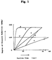
- Example 2 Experiments similar to Example 1 were carried out according to various suction patterns shown in Figure 1. The results are shown in Table 2.
- the suction pattern was set as follows: Time from Start of Suction (sec) 0 10 20 30 Degree of Pressure Reduction (mmIIg) 0 30 110 170
- Suction was conducted at a low speed for 10 seconds from the start of suction, and then elevated to a middle speed for 20 seconds of the latter period.
- the time requiring that the degree of pressure reduction reaches 150 mmHg was 25 seconds or more.
- the degree of pressure reduction reached 150 mmHg after 22.5 seconds.
- the time that the degree of pressure reduction reaches 150 mmHg was detected, and in the case of high hematocrit value blood, the suction period was lengthened with keeping the degree of pressure reduction at 170 mmHg.
Abstract
Description
- 10
- Holder body
- 11
- Filter chamber
- 12
- Disc portion
- 13
- Flange
- 14
- Blood inlet
- 15
- Space
- 16
- Spacer
- 17
- Flap
- 20
- Cap
- 21
- Step
- 22
- Plasma receiver
- 23
- Flange
- 24
- Plasma passage
- 25
- Projection (Adhering inhibition means)
- 26
- Pent-roof
- 27
- Partition wall
- 28
- Suction port
- 30
- Blood filtering material
- 31
- Nylon mesh
- 32
- Glass fiber flake layer
- 33
- Polysulfone microporous membrane


| Time from Start of Suction (sec) | 0 | 10 | 20 | 30 |
| Degree of Pressure Reduction (mmIIg) | 0 | 30 | 110 | 170 |

Claims (7)
- A method of filtering blood using a filtering material comprising glass fiber filter, which comprises keeping pressure difference between blood inlet side and filtrate outlet side 50 mmHg or less at least for 5 seconds from contacting the blood to be filtered, and keeping the pressure difference 200 mmHg or less throughout the filtering of the blood.
- The method of filtering blood of claim 1 which further comprises the pressure difference between blood inlet side and filtrate outlet side is detected, and suction and/or pressure rate is controlled according to the pressure difference.
- The method of filtering blood of claim 1 wherein said glass fiber filter has a density of 0.05 to 0.13.
- The method of filtering blood of claim 3 wherein said filtering material consists essentially of the glass fiber filter and a microporous membrane.
- The method of filtering blood of claim 4 wherein said microporous membrane is polysulfone microporous membrane.
- The method of filtering blood of claim 1 wherein said 50 mmHg or less is 30 mmHg or less.
- The method of filtering blood of claim 1 wherein said 200 mmHg or less is 170 mmHg or less.
Applications Claiming Priority (3)
| Application Number | Priority Date | Filing Date | Title |
|---|---|---|---|
| JP193783/97 | 1997-07-18 | ||
| JP19378397A JP3903098B2 (en) | 1997-07-18 | 1997-07-18 | Blood filtration method |
| JP19378397 | 1997-07-18 |
Publications (2)
| Publication Number | Publication Date |
|---|---|
| EP0893130A1 true EP0893130A1 (en) | 1999-01-27 |
| EP0893130B1 EP0893130B1 (en) | 2003-10-08 |
Family
ID=16313735
Family Applications (1)
| Application Number | Title | Priority Date | Filing Date |
|---|---|---|---|
| EP98113356A Expired - Lifetime EP0893130B1 (en) | 1997-07-18 | 1998-07-17 | Method of filtering blood |
Country Status (4)
| Country | Link |
|---|---|
| US (1) | US6045699A (en) |
| EP (1) | EP0893130B1 (en) |
| JP (1) | JP3903098B2 (en) |
| DE (1) | DE69818759T2 (en) |
Cited By (2)
| Publication number | Priority date | Publication date | Assignee | Title |
|---|---|---|---|---|
| EP2264453A1 (en) * | 2009-06-17 | 2010-12-22 | Leukocare Ag | Blood filter and method for filtering blood |
| DE102009022605B4 (en) | 2009-05-26 | 2019-07-25 | Lmb Lab Med Blutbank Technologie Gmbh | Method and device for separating whole blood |
Families Citing this family (25)
| Publication number | Priority date | Publication date | Assignee | Title |
|---|---|---|---|---|
| JPH11237378A (en) * | 1998-02-19 | 1999-08-31 | Fuji Photo Film Co Ltd | Method for separating serum from whole blood |
| JP2000180443A (en) * | 1998-12-15 | 2000-06-30 | Fuji Photo Film Co Ltd | Recovery method of haemofiltration residue |
| JP2000180442A (en) * | 1998-12-15 | 2000-06-30 | Fuji Photo Film Co Ltd | Hemofilter |
| JP3715123B2 (en) * | 1998-12-28 | 2005-11-09 | 富士写真フイルム株式会社 | Blood filtration unit |
| JP3990505B2 (en) * | 1999-02-02 | 2007-10-17 | 富士フイルム株式会社 | Blood component analysis method |
| US6869405B2 (en) * | 2001-03-30 | 2005-03-22 | Becton, Dickinson And Company | Blunt cannula and filter assembly and method of use with point-of-care testing cartridge |
| US6548646B1 (en) * | 2001-08-23 | 2003-04-15 | Bio-Rad Laboratories, Inc. | Reference control for high-sensitivity C-reactive protein testing |
| DE10150549A1 (en) | 2001-10-12 | 2003-04-17 | Roche Diagnostics Gmbh | Separation module, useful for the separation of corpuscles from blood, comprises two channels from a junction with a faster flow in one channel taking most of the particles, and a slower flow with few particles through the other channel |
| CA2504603C (en) * | 2002-11-19 | 2012-11-13 | Sekisui Chemical Co., Ltd. | Plasma or serum separation membrane and filter apparatus including the plasma or serum separation membrane |
| US7128836B2 (en) * | 2004-03-08 | 2006-10-31 | Potito De Paolis | Dialysis device |
| US7799235B2 (en) * | 2004-07-23 | 2010-09-21 | Contech Stormwater Solutions, Inc. | Fluid filter system and related method |
| JP5038131B2 (en) * | 2005-05-17 | 2012-10-03 | ユニバーサル・バイオ・リサーチ株式会社 | Filter processing method, filter enclosing chip, and filter processing apparatus |
| US8110099B2 (en) * | 2007-05-09 | 2012-02-07 | Contech Stormwater Solutions Inc. | Stormwater filter assembly |
| US8287726B2 (en) | 2007-08-15 | 2012-10-16 | Monteco Ltd | Filter for removing sediment from water |
| US8008068B2 (en) * | 2008-02-29 | 2011-08-30 | Light Pointe Medical, Inc. | Nonhemolytic optical sensor with enhanced reflectance |
| US20090219509A1 (en) * | 2008-02-29 | 2009-09-03 | Hiroshi Nomura | Optical sensor with enhanced reflectance |
| DE102010030238A1 (en) | 2010-06-17 | 2011-12-22 | Lmb Lab Med Blutbank Technologie Gmbh | Flow filter for separating blood into plasma and cellular components |
| DE102011076228A1 (en) * | 2011-05-20 | 2012-11-22 | Siemens Ag | Arrangement and method for filtration |
| US9427707B2 (en) | 2012-08-10 | 2016-08-30 | Jean I. Montagu | Filtering blood |
| DE102013012677A1 (en) * | 2013-07-31 | 2015-02-05 | Mann + Hummel Gmbh | PROCESS FOR REMOVING BLOOD PLASMA / SERUM OF FULL BLOOD |
| DE102013012678A1 (en) * | 2013-07-31 | 2015-02-05 | Mann + Hummel Gmbh | FLAT FILTER MEDIA FOR THE DISTRIBUTION OF PLASMA OR SERUM OF FULL BLOOD |
| DE102013012667B4 (en) * | 2013-07-31 | 2022-06-23 | Mann+Hummel Gmbh | Bulk blood filter |
| EP3782730B1 (en) | 2015-09-01 | 2024-01-10 | Becton, Dickinson and Company | Depth filtration device for separating specimen phases |
| JP6805637B2 (en) * | 2016-08-26 | 2020-12-23 | コニカミノルタ株式会社 | Hematocrit value measuring method, hematocrit value measuring device, amount of substance to be measured, and amount of substance to be measured |
| EP4213966A1 (en) * | 2020-09-21 | 2023-07-26 | Sequoia Biolabs LLC | Functionalized filters |
Citations (6)
| Publication number | Priority date | Publication date | Assignee | Title |
|---|---|---|---|---|
| EP0076665A2 (en) * | 1981-10-02 | 1983-04-13 | E.I. Du Pont De Nemours And Company | Method and apparatus for plasmapheresis |
| US4477575A (en) * | 1980-08-05 | 1984-10-16 | Boehringer Mannheim Gmbh | Process and composition for separating plasma or serum from whole blood |
| US4619639A (en) * | 1980-02-05 | 1986-10-28 | Asahi Medical Co., Ltd. | Method and apparatus for low pressure filtration of plasma from blood |
| US5139685A (en) * | 1991-03-26 | 1992-08-18 | Gds Technology, Inc. | Blood separation filter assembly and method |
| EP0785012A1 (en) * | 1996-01-19 | 1997-07-23 | Fuji Photo Film Co., Ltd. | Blood filter unit |
| EP0785430A1 (en) * | 1996-01-19 | 1997-07-23 | Fuji Photo Film Co., Ltd. | Separation of plasma or serum sample from whole blood |
Family Cites Families (3)
| Publication number | Priority date | Publication date | Assignee | Title |
|---|---|---|---|---|
| JPS6138608A (en) * | 1984-07-31 | 1986-02-24 | Fuji Photo Film Co Ltd | Equipment and process for separating solid from liquid |
| US5423989A (en) * | 1988-05-19 | 1995-06-13 | Chemtrack, Inc. | Plasma forming device |
| US5460777A (en) * | 1992-03-16 | 1995-10-24 | Fuji Photo Film Co., Ltd. | Analytical element for whole blood analysis |
-
1997
- 1997-07-18 JP JP19378397A patent/JP3903098B2/en not_active Expired - Fee Related
-
1998
- 1998-07-17 EP EP98113356A patent/EP0893130B1/en not_active Expired - Lifetime
- 1998-07-17 US US09/118,633 patent/US6045699A/en not_active Expired - Lifetime
- 1998-07-17 DE DE69818759T patent/DE69818759T2/en not_active Expired - Lifetime
Patent Citations (7)
| Publication number | Priority date | Publication date | Assignee | Title |
|---|---|---|---|---|
| US4619639A (en) * | 1980-02-05 | 1986-10-28 | Asahi Medical Co., Ltd. | Method and apparatus for low pressure filtration of plasma from blood |
| US4477575A (en) * | 1980-08-05 | 1984-10-16 | Boehringer Mannheim Gmbh | Process and composition for separating plasma or serum from whole blood |
| US4477575B1 (en) * | 1980-08-05 | 1992-04-21 | Boehringer Mannheim Gmbh | |
| EP0076665A2 (en) * | 1981-10-02 | 1983-04-13 | E.I. Du Pont De Nemours And Company | Method and apparatus for plasmapheresis |
| US5139685A (en) * | 1991-03-26 | 1992-08-18 | Gds Technology, Inc. | Blood separation filter assembly and method |
| EP0785012A1 (en) * | 1996-01-19 | 1997-07-23 | Fuji Photo Film Co., Ltd. | Blood filter unit |
| EP0785430A1 (en) * | 1996-01-19 | 1997-07-23 | Fuji Photo Film Co., Ltd. | Separation of plasma or serum sample from whole blood |
Cited By (7)
| Publication number | Priority date | Publication date | Assignee | Title |
|---|---|---|---|---|
| DE102009022605B4 (en) | 2009-05-26 | 2019-07-25 | Lmb Lab Med Blutbank Technologie Gmbh | Method and device for separating whole blood |
| EP2264453A1 (en) * | 2009-06-17 | 2010-12-22 | Leukocare Ag | Blood filter and method for filtering blood |
| WO2010146123A1 (en) * | 2009-06-17 | 2010-12-23 | Leukocare Ag | Blood filter and method for filtering blood |
| CN102803958A (en) * | 2009-06-17 | 2012-11-28 | 白血球保健股份有限公司 | Blood filter and method for filtering blood |
| EP2631645A1 (en) * | 2009-06-17 | 2013-08-28 | Leukocare AG | Blood filtering kit |
| CN102803958B (en) * | 2009-06-17 | 2014-08-20 | 白血球保健股份有限公司 | Blood filter and method for filtering blood |
| US10406271B2 (en) | 2009-06-17 | 2019-09-10 | Leukocare Ag | Method for filtering blood to produce plasma or serum |
Also Published As
| Publication number | Publication date |
|---|---|
| JP3903098B2 (en) | 2007-04-11 |
| DE69818759T2 (en) | 2004-11-25 |
| DE69818759D1 (en) | 2003-11-13 |
| US6045699A (en) | 2000-04-04 |
| JPH1138000A (en) | 1999-02-12 |
| EP0893130B1 (en) | 2003-10-08 |
Similar Documents
| Publication | Publication Date | Title |
|---|---|---|
| EP0893130B1 (en) | Method of filtering blood | |
| EP1291062B1 (en) | Blood filter unit | |
| US5996811A (en) | Plasma collecting device | |
| EP0785430B1 (en) | Separation of plasma or serum sample from whole blood | |
| US6074869A (en) | Fibrous web for processing a fluid | |
| US6220453B1 (en) | Blood filter unit | |
| EP0937981B1 (en) | Method of separating serum from whole blood | |
| JP2004361419A (en) | Blood filtering unit | |
| US6375856B1 (en) | Method of recovering blood filtration residues | |
| US6328167B1 (en) | Blood filter cartridge | |
| JP4078460B2 (en) | Plasma separation filter, plasma separation method and plasma separation apparatus using the same | |
| JP3990505B2 (en) | Blood component analysis method | |
| JP3765661B2 (en) | Blood filtration unit | |
| JP3644169B2 (en) | Plasma or serum separation filter and plasma or serum separation method | |
| JP3695680B2 (en) | Blood filtration unit | |
| JPH1138001A (en) | Blood filtration unit | |
| JPH10185909A (en) | Blood filtration unit | |
| JPH10227788A (en) | Blood filtering unit | |
| JPH1138003A (en) | Blood filtration device | |
| JPH10170508A (en) | Blood-filtering method | |
| JP2000180444A (en) | Hemofilter | |
| JPH116829A (en) | Method for separation of serum from whole blood | |
| JPH11290295A (en) | Blood serum sampling device |
Legal Events
| Date | Code | Title | Description |
|---|---|---|---|
| PUAI | Public reference made under article 153(3) epc to a published international application that has entered the european phase |
Free format text: ORIGINAL CODE: 0009012 |
|
| AK | Designated contracting states |
Kind code of ref document: A1 Designated state(s): DE GB |
|
| AX | Request for extension of the european patent |
Free format text: AL;LT;LV;MK;RO;SI |
|
| 17P | Request for examination filed |
Effective date: 19990609 |
|
| AKX | Designation fees paid |
Free format text: DE GB |
|
| 17Q | First examination report despatched |
Effective date: 20020827 |
|
| GRAH | Despatch of communication of intention to grant a patent |
Free format text: ORIGINAL CODE: EPIDOS IGRA |
|
| GRAH | Despatch of communication of intention to grant a patent |
Free format text: ORIGINAL CODE: EPIDOS IGRA |
|
| GRAA | (expected) grant |
Free format text: ORIGINAL CODE: 0009210 |
|
| AK | Designated contracting states |
Kind code of ref document: B1 Designated state(s): DE GB |
|
| REG | Reference to a national code |
Ref country code: GB Ref legal event code: FG4D |
|
| REF | Corresponds to: |
Ref document number: 69818759 Country of ref document: DE Date of ref document: 20031113 Kind code of ref document: P |
|
| PLBE | No opposition filed within time limit |
Free format text: ORIGINAL CODE: 0009261 |
|
| STAA | Information on the status of an ep patent application or granted ep patent |
Free format text: STATUS: NO OPPOSITION FILED WITHIN TIME LIMIT |
|
| 26N | No opposition filed |
Effective date: 20040709 |
|
| REG | Reference to a national code |
Ref country code: GB Ref legal event code: 732E |
|
| PGFP | Annual fee paid to national office [announced via postgrant information from national office to epo] |
Ref country code: DE Payment date: 20110622 Year of fee payment: 14 Ref country code: GB Payment date: 20110713 Year of fee payment: 14 |
|
| GBPC | Gb: european patent ceased through non-payment of renewal fee |
Effective date: 20120717 |
|
| PG25 | Lapsed in a contracting state [announced via postgrant information from national office to epo] |
Ref country code: GB Free format text: LAPSE BECAUSE OF NON-PAYMENT OF DUE FEES Effective date: 20120717 Ref country code: DE Free format text: LAPSE BECAUSE OF FAILURE TO SUBMIT A TRANSLATION OF THE DESCRIPTION OR TO PAY THE FEE WITHIN THE PRESCRIBED TIME-LIMIT Effective date: 20130201 |
|
| REG | Reference to a national code |
Ref country code: DE Ref legal event code: R119 Ref document number: 69818759 Country of ref document: DE Effective date: 20130201 |