EP0891865B1 - Inkjet printer service station controlled by data from consumable parts with incorporated memory devices - Google Patents
Inkjet printer service station controlled by data from consumable parts with incorporated memory devices Download PDFInfo
- Publication number
- EP0891865B1 EP0891865B1 EP98305587A EP98305587A EP0891865B1 EP 0891865 B1 EP0891865 B1 EP 0891865B1 EP 98305587 A EP98305587 A EP 98305587A EP 98305587 A EP98305587 A EP 98305587A EP 0891865 B1 EP0891865 B1 EP 0891865B1
- Authority
- EP
- European Patent Office
- Prior art keywords
- service station
- printhead
- cartridge
- control procedure
- printing system
- Prior art date
- Legal status (The legal status is an assumption and is not a legal conclusion. Google has not performed a legal analysis and makes no representation as to the accuracy of the status listed.)
- Expired - Lifetime
Links
Images


Classifications
-
- B—PERFORMING OPERATIONS; TRANSPORTING
- B41—PRINTING; LINING MACHINES; TYPEWRITERS; STAMPS
- B41J—TYPEWRITERS; SELECTIVE PRINTING MECHANISMS, i.e. MECHANISMS PRINTING OTHERWISE THAN FROM A FORME; CORRECTION OF TYPOGRAPHICAL ERRORS
- B41J2/00—Typewriters or selective printing mechanisms characterised by the printing or marking process for which they are designed
- B41J2/005—Typewriters or selective printing mechanisms characterised by the printing or marking process for which they are designed characterised by bringing liquid or particles selectively into contact with a printing material
- B41J2/01—Ink jet
- B41J2/17—Ink jet characterised by ink handling
- B41J2/175—Ink supply systems ; Circuit parts therefor
- B41J2/17503—Ink cartridges
- B41J2/17553—Outer structure
-
- B—PERFORMING OPERATIONS; TRANSPORTING
- B41—PRINTING; LINING MACHINES; TYPEWRITERS; STAMPS
- B41J—TYPEWRITERS; SELECTIVE PRINTING MECHANISMS, i.e. MECHANISMS PRINTING OTHERWISE THAN FROM A FORME; CORRECTION OF TYPOGRAPHICAL ERRORS
- B41J2/00—Typewriters or selective printing mechanisms characterised by the printing or marking process for which they are designed
- B41J2/005—Typewriters or selective printing mechanisms characterised by the printing or marking process for which they are designed characterised by bringing liquid or particles selectively into contact with a printing material
- B41J2/01—Ink jet
- B41J2/135—Nozzles
- B41J2/165—Preventing or detecting of nozzle clogging, e.g. cleaning, capping or moistening for nozzles
- B41J2/16517—Cleaning of print head nozzles
- B41J2/16535—Cleaning of print head nozzles using wiping constructions
- B41J2/16538—Cleaning of print head nozzles using wiping constructions with brushes or wiper blades perpendicular to the nozzle plate
-
- B—PERFORMING OPERATIONS; TRANSPORTING
- B41—PRINTING; LINING MACHINES; TYPEWRITERS; STAMPS
- B41J—TYPEWRITERS; SELECTIVE PRINTING MECHANISMS, i.e. MECHANISMS PRINTING OTHERWISE THAN FROM A FORME; CORRECTION OF TYPOGRAPHICAL ERRORS
- B41J2/00—Typewriters or selective printing mechanisms characterised by the printing or marking process for which they are designed
- B41J2/005—Typewriters or selective printing mechanisms characterised by the printing or marking process for which they are designed characterised by bringing liquid or particles selectively into contact with a printing material
- B41J2/01—Ink jet
- B41J2/17—Ink jet characterised by ink handling
- B41J2/175—Ink supply systems ; Circuit parts therefor
- B41J2/17503—Ink cartridges
- B41J2/17506—Refilling of the cartridge
-
- B—PERFORMING OPERATIONS; TRANSPORTING
- B41—PRINTING; LINING MACHINES; TYPEWRITERS; STAMPS
- B41J—TYPEWRITERS; SELECTIVE PRINTING MECHANISMS, i.e. MECHANISMS PRINTING OTHERWISE THAN FROM A FORME; CORRECTION OF TYPOGRAPHICAL ERRORS
- B41J2/00—Typewriters or selective printing mechanisms characterised by the printing or marking process for which they are designed
- B41J2/005—Typewriters or selective printing mechanisms characterised by the printing or marking process for which they are designed characterised by bringing liquid or particles selectively into contact with a printing material
- B41J2/01—Ink jet
- B41J2/17—Ink jet characterised by ink handling
- B41J2/175—Ink supply systems ; Circuit parts therefor
- B41J2/17503—Ink cartridges
- B41J2/1752—Mounting within the printer
- B41J2/17523—Ink connection
-
- B—PERFORMING OPERATIONS; TRANSPORTING
- B41—PRINTING; LINING MACHINES; TYPEWRITERS; STAMPS
- B41J—TYPEWRITERS; SELECTIVE PRINTING MECHANISMS, i.e. MECHANISMS PRINTING OTHERWISE THAN FROM A FORME; CORRECTION OF TYPOGRAPHICAL ERRORS
- B41J2/00—Typewriters or selective printing mechanisms characterised by the printing or marking process for which they are designed
- B41J2/005—Typewriters or selective printing mechanisms characterised by the printing or marking process for which they are designed characterised by bringing liquid or particles selectively into contact with a printing material
- B41J2/01—Ink jet
- B41J2/17—Ink jet characterised by ink handling
- B41J2/175—Ink supply systems ; Circuit parts therefor
- B41J2/17503—Ink cartridges
- B41J2/17543—Cartridge presence detection or type identification
- B41J2/17546—Cartridge presence detection or type identification electronically
-
- B—PERFORMING OPERATIONS; TRANSPORTING
- B41—PRINTING; LINING MACHINES; TYPEWRITERS; STAMPS
- B41J—TYPEWRITERS; SELECTIVE PRINTING MECHANISMS, i.e. MECHANISMS PRINTING OTHERWISE THAN FROM A FORME; CORRECTION OF TYPOGRAPHICAL ERRORS
- B41J2/00—Typewriters or selective printing mechanisms characterised by the printing or marking process for which they are designed
- B41J2/005—Typewriters or selective printing mechanisms characterised by the printing or marking process for which they are designed characterised by bringing liquid or particles selectively into contact with a printing material
- B41J2/01—Ink jet
- B41J2/17—Ink jet characterised by ink handling
- B41J2/175—Ink supply systems ; Circuit parts therefor
- B41J2/17503—Ink cartridges
- B41J2/17543—Cartridge presence detection or type identification
- B41J2/1755—Cartridge presence detection or type identification mechanically
-
- B—PERFORMING OPERATIONS; TRANSPORTING
- B41—PRINTING; LINING MACHINES; TYPEWRITERS; STAMPS
- B41J—TYPEWRITERS; SELECTIVE PRINTING MECHANISMS, i.e. MECHANISMS PRINTING OTHERWISE THAN FROM A FORME; CORRECTION OF TYPOGRAPHICAL ERRORS
- B41J25/00—Actions or mechanisms not otherwise provided for
- B41J25/34—Bodily-changeable print heads or carriages
-
- B—PERFORMING OPERATIONS; TRANSPORTING
- B41—PRINTING; LINING MACHINES; TYPEWRITERS; STAMPS
- B41J—TYPEWRITERS; SELECTIVE PRINTING MECHANISMS, i.e. MECHANISMS PRINTING OTHERWISE THAN FROM A FORME; CORRECTION OF TYPOGRAPHICAL ERRORS
- B41J2/00—Typewriters or selective printing mechanisms characterised by the printing or marking process for which they are designed
- B41J2/005—Typewriters or selective printing mechanisms characterised by the printing or marking process for which they are designed characterised by bringing liquid or particles selectively into contact with a printing material
- B41J2/01—Ink jet
- B41J2/17—Ink jet characterised by ink handling
- B41J2/175—Ink supply systems ; Circuit parts therefor
- B41J2/17566—Ink level or ink residue control
- B41J2002/17569—Ink level or ink residue control based on the amount printed or to be printed
-
- B—PERFORMING OPERATIONS; TRANSPORTING
- B41—PRINTING; LINING MACHINES; TYPEWRITERS; STAMPS
- B41J—TYPEWRITERS; SELECTIVE PRINTING MECHANISMS, i.e. MECHANISMS PRINTING OTHERWISE THAN FROM A FORME; CORRECTION OF TYPOGRAPHICAL ERRORS
- B41J2/00—Typewriters or selective printing mechanisms characterised by the printing or marking process for which they are designed
- B41J2/005—Typewriters or selective printing mechanisms characterised by the printing or marking process for which they are designed characterised by bringing liquid or particles selectively into contact with a printing material
- B41J2/01—Ink jet
- B41J2/17—Ink jet characterised by ink handling
- B41J2/175—Ink supply systems ; Circuit parts therefor
- B41J2/17566—Ink level or ink residue control
- B41J2002/17573—Ink level or ink residue control using optical means for ink level indication
-
- B—PERFORMING OPERATIONS; TRANSPORTING
- B41—PRINTING; LINING MACHINES; TYPEWRITERS; STAMPS
- B41J—TYPEWRITERS; SELECTIVE PRINTING MECHANISMS, i.e. MECHANISMS PRINTING OTHERWISE THAN FROM A FORME; CORRECTION OF TYPOGRAPHICAL ERRORS
- B41J2/00—Typewriters or selective printing mechanisms characterised by the printing or marking process for which they are designed
- B41J2/005—Typewriters or selective printing mechanisms characterised by the printing or marking process for which they are designed characterised by bringing liquid or particles selectively into contact with a printing material
- B41J2/01—Ink jet
- B41J2/17—Ink jet characterised by ink handling
- B41J2/175—Ink supply systems ; Circuit parts therefor
- B41J2/17566—Ink level or ink residue control
- B41J2002/17576—Ink level or ink residue control using a floater for ink level indication
Definitions
- This invention relates to inkjet printer systems that employ replaceable, consumable parts and, more particularly, to an inkjet printer which includes a service station whose operation is controlled by a procedure stored on memories that are integral to the consumable parts.
- print heads incorporate a parameter memory for storage of operating parameters such as: drop generator driver frequency, ink pressure and drop charging values (see “Storage of Operating Parameters in Memory Integral with Print Head", Lonis, Xerox Disclosure Journal, Volume 8, No. 6, November/December 1983, page 503).
- U. S. Patent 5,138,344 to Ujita indicates that an ink-containing replaceable cartridge can be provided with an integral information device (i.e., a resistor element, magnetic medium, bar code, integrated circuit or ROM), for storage of information relating to control parameters for the inkjet printer.
- Murray et al. in U.S. Patent 5,610,635 describe a printer ink cartridge which includes a memory for storing various parameters related to ink contained within the cartridge.
- Inkjet printers mount inkjet printheads on a scanning carriage which is scanned across a media sheet, as the sheet is fed by the printer's sheet feed apparatus. At one extreme of the scan path is positioned a mechanism for maintaining the printhead in good working order. That mechanism is called a “service station” and is provided with both (i) rubber caps that protect the printhead's nozzles and nozzle plate during periods of non-use and (ii) a wiping mechanism for removing accumulated crust which builds up on the nozzle plate over time.
- An ink plug is an accumulated amount of dried ink which plugs a nozzle and inhibits drop ejection.
- the dried ink builds up during non-firing time in both the capped and uncapped states, but more slowly in the capped state.
- Ink crust on the nozzle plate builds up during printing and is a layer of dried ink which accumulates as a result of an ink aerosol that settles thereon.
- Ink plugs can be ejected by firing a nozzle (i.e., "spitting") into a spittoon that is typically positioned adjacent to the service station.
- the nozzle is repeatedly fired until the effect of the plug is eliminated.
- the number of firings required to dislodge an ink plug is determined by whether the printhead has been capped or uncapped; the total time since the last firing; ambient humidity and temperature; and the type of ink. As inks become faster drying and more permanent, the number of firings needed to clear a nozzle increases.
- Pulsewarming is one way to reduce the required number of firings to clear a nozzle.
- Most inkjet printheads employ heater resistors to cause ejection of an ink droplet through a nozzle. Pulsewarming is the application of a low level of current to the heater resistors which is insufficient to cause ink ejection, but is sufficient to warm the ink substrate and hence the ink. The heated ink acts as a better solvent in removing ink plugs.
- the printer firmware included parameters which controlled the number of "spits" of ink that were used to dislodge an ink plug and the current level required to achieve pulsewarming.
- ink chemistries and printer designs are continually evolving, it is difficult to establish optimal spitting and pulsewarming criteria at the time of introduction of a printer to the marketplace.
- the aforesaid parameters are "moving targets"- even after a printer model is introduced.
- Ink crust is normally removed by wiping the nozzle plate at the service station.
- a solvent e.g., polyethylene glycol
- the order of spitting, wiping and cleaning can be important to the proper maintenance of the printhead
- EP-A-0764535 describes an inkjet recording apparatus in which a replaceable ink tank and an inkjet head each comprise a respective memory for storing tank information and head information which can be read by a processor to determine optimal driving conditions for a recovery procedure from a table, based on the stored tank and head information.
- an inkjet printing system as defined in claim 1.
- Fig. 1a is a perspective view of an inkjet printer (with cover removed), which incorporates an embodiment of the present invention.
- Fig. 1b is a bock diagram of components of the inkjet printer of Fig. la.
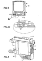
- Fig. 2 is a schematic sectional view of a replaceable ink cartridge used with the inkjet printer of Figs. 1a and 1b.
- Fig. 2a is an expanded view of Fig. 2 showing details of a cartridge memory installed on the ink cartridge.
- Fig. 3 is a perspective view of an inkjet printhead employed with an embodiment of the present invention.
- Fig. 1a illustrates a perspective view of an inkjet printer 1 in accordance with a preferred embodiment of the invention.
- a tray 2 holds a supply of input paper or other print media.
- a printing operation is initiated, a sheet of paper is fed into printer 1 and is then brought around in a U direction towards an output tray 3.
- the sheet is stopped in a print zone 4 and a scanning carriage 5, containing plural, removable color printheads 6, is scanned across the sheet for printing a swath of ink thereon.
- the process repeats until the entire sheet has been printed, at which point, it is ejected onto output tray 3.
- Printheads 6 are, respectively, fluidically coupled to four removable ink cartridges 7 holding Cyan, Magenta, Yellow and Black inks. Since black ink tends to be depleted most rapidly, the black ink cartridge has a larger capacity than the other cartridges. As will be understood from the description which follows, each printhead and ink cartridge is provided with an integral memory device which stores data that is used by printer 1 to control its printing operations.
- a printhead service station 8 and a spittoon 9 are positioned to the right extremity of the printhead scan path.
- Service station 8 includes a mechanism for wiping the nozzle plate of the printheads as they are moved by the carriage into and out of a parked position at service station 8.
- Service station 8 also includes a mechanism for capping the nozzle plates when the printheads are in the parked position.
- U. S. Patent 5,155,497 to Martin et al. (assigned to the same Assignee as this Application) describes the structure and operation of a service station usable with the invention hereof as disclosed in claim 1.
- Fig. 1b illustrates pluggable printhead 12 which includes a print element 14 and an integrally mounted printhead memory 16.
- Printhead 12 is pluggably removable from printer 1 via interconnects 18.
- An ink cartridge 20 is also pluggably removable from printer 1 via electrical interconnect 22 and fluidic interconnect 24.
- Ink cartridge 20 includes an ink reservoir 26 and an integral cartridge memory 28.
- Service station 8 is also present in printer 1, as described above. The contents of memories 16 and 28 will be considered in detail below and, as will be understood, are instrumental in enabling real time control of service station 8.
- Ink cartridge 20, printhead 12 and service station 8 are interconnected to a microprocessor 30 which includes both electronics and firmware for the control of the various printer sub-assemblies.
- a service station control procedure is executed by printing system 1 at various times during printing for the purpose of maintaining print quality.
- This control procedure can be incorporated in the driver, in the printer firmware, and/or in information storage devices 16 and 28.
- storage devices 16 and 28 provide control parameters for service station operation.
- information storage devices 16 and 28 provide parts of or all of the entire service station control procedure.
- control data may be broken into two groups. The first group controls when and how much servicing occurs. The second group controls how the servicing is performed, including the order of wiping, spitting and cleaning. Either group may be altered of enhanced as described herein.
- information storage devices can include date codes or revision numbers associated with parameters and/or control procedures to assure that a most recent version of the service station control procedure is used.
- a host processor 36 is connected to microprocessor 30 and includes a central processing unit (CPU) 38 and a software printer driver 40.
- a monitor 41 is connected to host processor 36 and is used to display various messages that are indicative of the state of inkjet printer 1.
- Fig. 2 illustrates a sectional view of ink cartridge 20.
- Ink cartridge 20 is pluggable into a receptacle (not shown) in inkjet printer 1 and includes both a fluidic interconnection and an electrical interconnection, both of which are accessible through bottom surface 42 via fluidic connector 44 and an electrical connector 46.
- Electrical connector 46 enables interconnection to a cartridge memory chip 28.
- connector 46 and memory chip 28 are shown in Fig. 2a, with connector 46 making contact to a mating connector in the receptacle within inkjet printer 1 when inkjet cartridge 20 is pluggably inserted thereinto.
- Fig. 3 is a perspective view of printhead 12 and illustrates the placement of printhead memory 16 thereon.
- a plurality of contacts 48 enables pluggable connection to printhead memory 16 as well as various electrical elements within printhead 12.
- Printhead 12 is a known, thermally-actuated inkjet printhead, with a print element (including a nozzle plate) positioned at surface 14. Behind each nozzle is an ink chamber with a heater resistor.
- a thermal sense resistor is positioned on the printhead and detects the temperature of the semiconductor substrate on which the heater resistors are positioned.
- a fluidic interconnect 50 connects ink cartridge 12, via ink flow path 24 (see Fig. 1), to ink reservoir 26 in ink cartridge 20.
- contacts 48 make electrical connection to a mating connector in the printer and fluidic interconnect 50 automatically mates to ink flow path 24 to enable a flow of ink thereto.
- encoded subroutines stored in cartridge memory 28 and printhead memory 16 enable microprocessor 34 to calculate control values for service station 8.
- each of memories 16 and 28 includes both factory-written data and printer-recorded data.
- Many parameters present in the memories are not directly relevant to this invention and will not be considered herein. The following is a list of parameters relevant to control of service station 8 that are stored within the aforesaid memories:
- service station control procedure 32 makes use of the above-indicated parameters to control the operation of service station 8.
- data from both memories 16 and 28 are utilized to arrive at an improved service station control value.
- the ability to periodically replace memories 16 and 28, as their host carriers (e.g., printhead 12 or ink cartridge 20) are replaced enables the manufacturer to provide updated parameters, on a continuing basis, to customers who already have installed printers.
- Service station control procedure 32 includes both a spitting algorithm and a wiping control algorithm.
- the spitting algorithm is used during an uncapped state (during or after printing) and just after a capped state(just before printing).
- the spitting algorithm receives signals from microprocessor 30 which enable it to determine the uncapped time of printhead 12.
- service station control procedure 32 accesses values which define the relationship between a number of spits versus time uncapped.
- signals are sent to the printing system to position printhead 12 in facing relation with spittoon 19 and to cause the required number of spits to occur through the nozzle(s).
- a similar process is used to provide the correct amount of spitting so that the nozzles will properly eject ink.
- printhead 12 is incremented to its park position to enable the wiping procedure to occur. If the procedure senses that a time period since a last wipe action has passed which exceeds the "time frequency of wiping" threshold (parameter 4 above), then a wiping action is ordered. If the time frequency of wiping threshold is not reached, but the number of pages printed between wipes reaches the threshold value given by parameter 5 above, then a wipe action is ordered. Note that the number of pages printed value is acquired from memory 16 on printhead 12 -- to accommodate the possibility that printhead 12 may have been moved from one printer to another.
- the number of wipes for each cleaning is determined by a wipe parameter, which defines the number of wipes that are performed on the nozzle plate to accomplish a desired level of cleaning.
- a wipe parameter which defines the number of wipes that are performed on the nozzle plate to accomplish a desired level of cleaning.
- this parameter and others will vary in accordance with the specific ink that is present in ink cartridge 20. Accordingly, those values are modified if a new ink type requires such a modification.
- the remaining parameters are self-evident and are utilized by the procedure to further control the wiping action.
- the printer driver or printer firmware may include a plurality of service station control procedures, each such procedure associated with an address.
- the selected address may then be a value which is encoded on memory 28 on each cartridge 20.
- driver-contained parameters and ink cartridge-contained parameters may be utilized.
- a new printer may be introduced with a first type of ink. If, after introduction, a second type of ink is discovered that drys faster and is otherwise fully compatible with the first ink, a new print cartridge would be introduced containing the new and faster-drying ink. By encoding the wiping and spitting parameters on the new ink cartridge, such parameters can be utilized by the printer without any requirement being placed upon the user to update the printer software.
- the memory can also contain software objects, for example, JAVA objects which could contain service station parameters, routines or both.
- This invention may be extended to not only optimize individual servicing parameters for a given service station routine -- but also to optimize an entire service station routine.
- Printhead servicing is typically done before, during, and after printing as well as in response to a user prompt. After market introduction of a printer, it may be desirable to change the entire servicing routine, including the order of servicing operations.
- an entire subroutine may be encoded on ink container memory element 28. During certain events or after certain time periods or amounts of usage, such a service subroutine (or subroutines) are accessed by the printing system. At such time, the subroutine from the ink container effectively takes control of printer maintenance.
- Subroutines #1 and #2 are generally as follows:
- New objects could be contained in memories 16 or 28. Duplicate names would be resolved at runtime by deferring to the object in the cartridge first, printhead second and finally the printer. This offers the advantage of using minimum memory when supplying new control information. Similarly, latest date codes or revision numbers would enjoy priority.
Description
- This invention relates to inkjet printer systems that employ replaceable, consumable parts and, more particularly, to an inkjet printer which includes a service station whose operation is controlled by a procedure stored on memories that are integral to the consumable parts.
- Substantially, all present-day copiers, printers, plotters, etc., include a controlling microprocessor which requires input control parameters to assure high quality production of documents. Since most such apparatus allows user-replacement of consumable items, various techniques have been developed to enable entry of such parameters.
- In regards to inkjet printers, it has been proposed that print heads incorporate a parameter memory for storage of operating parameters such as: drop generator driver frequency, ink pressure and drop charging values (see "Storage of Operating Parameters in Memory Integral with Print Head", Lonis, Xerox Disclosure Journal,
Volume 8, No. 6, November/December 1983, page 503). U. S. Patent 5,138,344 to Ujita, entitled "Inkjet Apparatus and Inkjet Cartridge Therefor", indicates that an ink-containing replaceable cartridge can be provided with an integral information device (i.e., a resistor element, magnetic medium, bar code, integrated circuit or ROM), for storage of information relating to control parameters for the inkjet printer. Murray et al. in U.S. Patent 5,610,635, describe a printer ink cartridge which includes a memory for storing various parameters related to ink contained within the cartridge. - U. S. Patent 5,365,312 to Hillmann et al., entitled "Arrangement for Printer Equipment Monitoring Reservoirs that Contain Printing Medium", describes the use of memory devices integral with ink reservoirs which store ink consumption data (for use by a coupled inkjet printer). European patent EP 0 720 916, entitled "Ink Supply Identification System for a Printer" describes the use of an ink supply having an integral EEPROM which is utilized to store data regarding the identity of the ink supply and its fill level.
- The prior art further teaches the use of consumable parts with integral memory for use in electrophotographic printers. In U. S. Patent 5,021,828 to Yamaguchi et al., entitled "Copying Apparatus having a Consumable Part", a toner cartridge is disclosed which includes a memory for storing data regarding to the state of consumption of toner in the cartridge. U. S. Patents 4,961,088 to Gilliland et al.; 4,803,521 to Honda; 5,184,181 to Kurando et al.; and 5,272,503 to LeSueur et al. all describe various replaceable toner cartridges for use in electrophotographic printers. Each cartridge incorporates a memory device for storing parameter data regarding the cartridge.
- Current inkjet printers mount inkjet printheads on a scanning carriage which is scanned across a media sheet, as the sheet is fed by the printer's sheet feed apparatus. At one extreme of the scan path is positioned a mechanism for maintaining the printhead in good working order. That mechanism is called a "service station" and is provided with both (i) rubber caps that protect the printhead's nozzles and nozzle plate during periods of non-use and (ii) a wiping mechanism for removing accumulated crust which builds up on the nozzle plate over time.
- Two problems confront most printheads, i.e., ink plugs and ink crust. An ink plug is an accumulated amount of dried ink which plugs a nozzle and inhibits drop ejection. The dried ink builds up during non-firing time in both the capped and uncapped states, but more slowly in the capped state. Ink crust on the nozzle plate builds up during printing and is a layer of dried ink which accumulates as a result of an ink aerosol that settles thereon.
- Ink plugs can be ejected by firing a nozzle (i.e., "spitting") into a spittoon that is typically positioned adjacent to the service station. The nozzle is repeatedly fired until the effect of the plug is eliminated. The number of firings required to dislodge an ink plug is determined by whether the printhead has been capped or uncapped; the total time since the last firing; ambient humidity and temperature; and the type of ink. As inks become faster drying and more permanent, the number of firings needed to clear a nozzle increases.
- "Pulsewarming" is one way to reduce the required number of firings to clear a nozzle. Most inkjet printheads employ heater resistors to cause ejection of an ink droplet through a nozzle. Pulsewarming is the application of a low level of current to the heater resistors which is insufficient to cause ink ejection, but is sufficient to warm the ink substrate and hence the ink. The heated ink acts as a better solvent in removing ink plugs.
- In the prior art, the printer firmware included parameters which controlled the number of "spits" of ink that were used to dislodge an ink plug and the current level required to achieve pulsewarming. However, because ink chemistries and printer designs are continually evolving, it is difficult to establish optimal spitting and pulsewarming criteria at the time of introduction of a printer to the marketplace. In other words, the aforesaid parameters are "moving targets"- even after a printer model is introduced.
- Ink crust is normally removed by wiping the nozzle plate at the service station. With new, more permanent and fast drying inks, it has been found that more effective wiping is accomplished when a solvent (e.g., polyethylene glycol) is placed on the absorbent material that is used as the wiper. In addition, the order of spitting, wiping and cleaning can be important to the proper maintenance of the printhead
- Clearly there are a number of factors which should be considered when undertaking to control an inkjet printer's service station to assure long printhead lifetime. Among the factors are those which are directly related to the removal of ink plugs and the wiping action. Since many of those factors are variable during the lifetime of a printer, the prior art has used conservative, compromise servicing routines to achieve a best case operation. However, such compromises do not lead to best quality print documents. Also, such compromise service routines can take more time than necessary, slowing down printing operations.
- Accordingly, it would be desirable to provide a print apparatus with an improved capability for adjustment of printer control functions.
- It would further be desirable to provide an improved printer control system which is able to update control parameters for a service station that are dependent upon current printer performance parameters.
- It would further be desirable to provide improved service station operation for an inkjet printer, wherein control parameters for the service station are read from plural consumable parts.
- It would be further desirable to be able to alter the servicing routine of the printer based on new software routines contained in plural consumable parts.
- EP-A-0764535 describes an inkjet recording apparatus in which a replaceable ink tank and an inkjet head each comprise a respective memory for storing tank information and head information which can be read by a processor to determine optimal driving conditions for a recovery procedure from a table, based on the stored tank and head information.
- In accordance with a first aspect of the present invention there is provided an inkjet printing system as defined in
claim 1. - In accordance with a second aspect of the present invention there is provided a method for controlling operation of an inkjet printing system as defined in claim 13.
- In accordance with a third aspect of the present invention there is provided a replaceable ink cartridge for an inkjet printing system as defined in
claim 20. - Fig. 1a is a perspective view of an inkjet printer (with cover removed), which incorporates an embodiment of the present invention.
- Fig. 1b is a bock diagram of components of the inkjet printer of Fig. la.
- Fig. 2 is a schematic sectional view of a replaceable ink cartridge used with the inkjet printer of Figs. 1a and 1b.
- Fig. 2a is an expanded view of Fig. 2 showing details of a cartridge memory installed on the ink cartridge.
- Fig. 3 is a perspective view of an inkjet printhead employed with an embodiment of the present invention.
- Fig. 1a illustrates a perspective view of an
inkjet printer 1 in accordance with a preferred embodiment of the invention. Atray 2 holds a
supply of input paper or other print media. When a printing operation is initiated, a sheet of paper is fed intoprinter 1 and is then brought around in a U direction towards anoutput tray 3. The sheet is stopped in a print zone 4 and a scanning carriage 5, containing plural, removable color printheads 6, is scanned across the sheet for printing a swath of ink thereon. The process repeats until the entire sheet has been printed, at which point, it is ejected ontooutput tray 3. - Printheads 6 are, respectively, fluidically coupled to four removable ink cartridges 7 holding Cyan, Magenta, Yellow and Black inks. Since black ink tends to be depleted most rapidly, the black ink cartridge has a larger capacity than the other cartridges. As will be understood from the description which follows, each printhead and ink cartridge is provided with an integral memory device which stores data that is used by
printer 1 to control its printing operations. - A
printhead service station 8 and a spittoon 9 (shown schematically) are positioned to the right extremity of the printhead scan path.Service station 8 includes a mechanism for wiping the nozzle plate of the printheads as they are moved by the carriage into and out of a parked position atservice station 8.Service station 8 also includes a mechanism for capping the nozzle plates when the printheads are in the parked position. As the invention hereof is not dependent upon the specific structure ofservice station 8, further detailed discussion thereof is not required. U. S. Patent 5,155,497 to Martin et al. (assigned to the same Assignee as this Application) describes the structure and operation of a service station usable with the invention hereof as disclosed inclaim 1. - Fig. 1b illustrates
pluggable printhead 12 which includes aprint element 14 and an integrally mountedprinthead memory 16.Printhead 12 is pluggably removable fromprinter 1 viainterconnects 18. Anink cartridge 20 is also pluggably removable fromprinter 1 viaelectrical interconnect 22 andfluidic interconnect 24.Ink cartridge 20 includes anink reservoir 26 and anintegral cartridge memory 28.Service station 8 is also present inprinter 1, as described above. The contents ofmemories service station 8. -
Ink cartridge 20,printhead 12 andservice station 8 are interconnected to amicroprocessor 30 which includes both electronics and firmware for the control of the various printer sub-assemblies. A service station control procedure is executed byprinting system 1 at various times during printing for the purpose of maintaining print quality. This control procedure can be incorporated in the driver, in the printer firmware, and/or ininformation storage devices storage devices information storage devices - A
host processor 36 is connected tomicroprocessor 30 and includes a central processing unit (CPU) 38 and asoftware printer driver 40. Amonitor 41 is connected to hostprocessor 36 and is used to display various messages that are indicative of the state ofinkjet printer 1. - Fig. 2 illustrates a sectional view of
ink cartridge 20.Ink cartridge 20 is pluggable into a receptacle (not shown) ininkjet printer 1 and includes both a fluidic interconnection and an electrical interconnection, both of which are accessible throughbottom surface 42 viafluidic connector 44 and anelectrical connector 46.Electrical connector 46 enables interconnection to acartridge memory chip 28. - An expanded view of
connector 46 andmemory chip 28 is shown in Fig. 2a, withconnector 46 making contact to a mating connector in the receptacle withininkjet printer 1 wheninkjet cartridge 20 is pluggably inserted thereinto. - Fig. 3 is a perspective view of
printhead 12 and illustrates the placement ofprinthead memory 16 thereon. A plurality ofcontacts 48 enables pluggable connection toprinthead memory 16 as well as various electrical elements withinprinthead 12.Printhead 12 is a known, thermally-actuated inkjet printhead, with a print element (including a nozzle plate) positioned atsurface 14. Behind each nozzle is an ink chamber with a heater resistor. A thermal sense resistor is positioned on the printhead and detects the temperature of the semiconductor substrate on which the heater resistors are positioned. Afluidic interconnect 50 connectsink cartridge 12, via ink flow path 24 (see Fig. 1), toink reservoir 26 inink cartridge 20. - When
printhead 12 is plugged into a receptacle (not shown) withininkjet printer 1,contacts 48 make electrical connection to a mating connector in the printer andfluidic interconnect 50 automatically mates to ink flowpath 24 to enable a flow of ink thereto. - As indicated above, encoded subroutines stored in
cartridge memory 28 andprinthead memory 16 enable microprocessor 34 to calculate control values forservice station 8. To accomplish control ofservice station 8, each ofmemories service station 8 that are stored within the aforesaid memories: - Factory-written data:
- 1.- number of spits versus time uncapped (=slope);
- 2.- number of spits versus time capped (=slope) ;
- 3.-maximum number of spits;
- 4.-time frequency of wiping;
- 5.-number of pages printed between wipes;
- 6.-number of drops fired between wipes;
- 7.-number of wipes for each cleaning;
- 8.-number of wipes before wiper is rewetted with solvent;
- 9.-amount of time before wiper is rewetted with solvent; and
- 10.-frequency of flushing of the printhead (i.e., placing a vacuum on the nozzles to withdraw contaminents, bubbless and/or ink).
-
- Printer-recorded data:
- 1.-number of drops fired;
- 2.-number of pages printed.
-
- As will be hereafter understood, service
station control procedure 32 makes use of the above-indicated parameters to control the operation ofservice station 8. In a number of instances, data from bothmemories memories printhead 12 or ink cartridge 20) are replaced, enables the manufacturer to provide updated parameters, on a continuing basis, to customers who already have installed printers. - Service
station control procedure 32 includes both a spitting algorithm and a wiping control algorithm. The spitting algorithm is used during an uncapped state (during or after printing) and just after a capped state(just before printing). The spitting algorithm receives signals frommicroprocessor 30 which enable it to determine the uncapped time ofprinthead 12. In accordance with the uncapped time indication, servicestation control procedure 32 accesses values which define the relationship between a number of spits versus time uncapped. In accordance with the determined number of spits, signals are sent to the printing system to positionprinthead 12 in facing relation with spittoon 19 and to cause the required number of spits to occur through the nozzle(s). When a printhead job is initiated after the printhead has been resting in a capped state, a similar process is used to provide the correct amount of spitting so that the nozzles will properly eject ink. - As regards the wiping algorithm,
printhead 12 is incremented to its park position to enable the wiping procedure to occur. If the procedure senses that a time period since a last wipe action has passed which exceeds the "time frequency of wiping" threshold (parameter 4 above), then a wiping action is ordered. If the time frequency of wiping threshold is not reached, but the number of pages printed between wipes reaches the threshold value given by parameter 5 above, then a wipe action is ordered. Note that the number of pages printed value is acquired frommemory 16 onprinthead 12 -- to accommodate the possibility thatprinthead 12 may have been moved from one printer to another. - The number of wipes for each cleaning is determined by a wipe parameter, which defines the number of wipes that are performed on the nozzle plate to accomplish a desired level of cleaning. Clearly this parameter, and others will vary in accordance with the specific ink that is present in
ink cartridge 20. Accordingly, those values are modified if a new ink type requires such a modification. The remaining parameters are self-evident and are utilized by the procedure to further control the wiping action. - In lieu of recording all of the service station parameters, on the memory element, the encoding thereof may take other forms. The printer driver or printer firmware may include a plurality of service station control procedures, each such procedure associated with an address. The selected address may then be a value which is encoded on
memory 28 on eachcartridge 20. Thus when the address is accessed frommemory 28, it enables the retrieval of the desired service station control procedure. Further, some combination of driver-contained parameters and ink cartridge-contained parameters may be utilized. - As an example, a new printer may be introduced with a first type of ink. If, after introduction, a second type of ink is discovered that drys faster and is otherwise fully compatible with the first ink, a new print cartridge would be introduced containing the new and faster-drying ink. By encoding the wiping and spitting parameters on the new ink cartridge, such parameters can be utilized by the printer without any requirement being placed upon the user to update the printer software. The memory can also contain software objects, for example, JAVA objects which could contain service station parameters, routines or both.
- This invention may be extended to not only optimize individual servicing parameters for a given service station routine -- but also to optimize an entire service station routine. Printhead servicing is typically done before, during, and after printing as well as in response to a user prompt. After market introduction of a printer, it may be desirable to change the entire servicing routine, including the order of servicing operations. To accomplish this, an entire subroutine may be encoded on ink
container memory element 28. During certain events or after certain time periods or amounts of usage, such a service subroutine (or subroutines) are accessed by the printing system. At such time, the subroutine from the ink container effectively takes control of printer maintenance. - The following is a specific example of a series of events which occur when a print job is sent to the printer:
- 1. Print job started (by the user);
- 2. Printer reads a preprint
service subroutine # 1 and a parameter set fromink cartridge memory 28; - 3. Printer executes
preprint subroutine # 1 prior to printing; - 4. Printer prints the print job, using parameters from the parameter set;
- 5. Printer executes postprint
service subroutine # 2 after printing. -
-
Subroutines # 1 and #2 are generally as follows: -
- 1) Label or tag (a set of bits that dictate that this is a service routine to be performed at the beginning of a print job.
- 2) Spit command (set of bits that tell the printer to carry out a spit action).
- 3) Spit parameters (set of bits that indicate a number of spits in accord with the time the printhead was in a capped position).
- 4) End (set of bits that signal the printing system that the end of the routine has been reached)
-
-
- 1) Label
- 2) Wipe command
- 3) Wipe parameters
- 4) Spit command
- 5) Spit parameters
- 6) End of subroutine.
-
- By providing both parameters and subroutines encoded on
ink cartridge memory 28, substantial flexibility is achieved to adjust such parameters or subroutines after a user purchases a printer. For instance, over time it may be determined thatSubroutine # 1 is more effective if a wipe command is executed prior to the spit command. It may also be determined that the spit command is not necessary forSubroutine # 2, or that the order of the spit and wipe operations should be changed. Parameters may be variable (dependent on time, amount of printing, etc.) or fixed (a set number of spits). The commands can also be subroutine calls themselves directing the sequence and control of the servicing process. The subroutines called may be located in the driver or in the printer firmware. Alternatively, an object oriented language can be used. New objects could be contained inmemories - It should be understood that the foregoing description is only illustrative of the invention. Various alternatives and modifications can be devised by those skilled in the art without departing from the invention as disclosed in the independent claims. While the above invention has been described in the context of an inkjet printer, those skilled in the art will realize that it is equally applicable to other printer/copier arrangements which employ inkjet print mechanisms and replaceable units therefor and wherein service station control procedures are programmable. Further, this invention can be used when the printhead and ink cartridge are one integrated, replaceable unit or when they are separately replaceable. Accordingly, the present invention is intended to embrace all such alternatives, modifications and variances which fall within the scope of the claims.
Claims (27)
- An inkjet printing system (10) comprising:a printhead (12) having nozzles for ejecting ink droplets;a service station (8) for capping and wiping said plural nozzles;replaceable cartridge means (20) for housing a supply of consumable marking media and including cartridge memory means (28) for recording a service station-control procedure; andprocessor means (30), including processor memory, coupled to said cartridge memory means (28) and responsive to said service station-control procedure read from said cartridge memory means(28) for operating said service station (8).
- The inkjet printing system (10) as recited in claim 1, wherein said printhead (12) is replaceable, said inkjet printing system (10) further comprising:printhead memory means (16) positioned on said printhead (12), for recording printhead-related parameters;said processor means (30) further responsive to a printhead-related parameter read from said printhead memory means (16) and said service station-control procedure read from said cartridge memory means (28) to control said service station (8).
- The inkjet printing system (10) as recited in claim 1, wherein said replaceable cartridge means (20) is an ink reservoir cartridge (20) that is pluggably insertable into said printing system (10), said cartridge memory means (28) forming an integral part of said cartridge means (20) and making electrical connection to said printing system (10) upon insertion of said cartridge means (20).
- The printing system (10) as recited in claim 1, wherein said service station-control procedure read from said cartridge memory means (28) further includes a value from which said processor means (30) derives a number of ink ejections for clearing a blocked nozzle.
- The printing system (10) as recited in claim 1, wherein said service station-control procedure read from said cartridge memory means (28) includes a value which is used by said processor means (30) to enable control of a number of wipes applied by said service station (8) to said printhead (12).
- The printing system (10) as recited in claim 1, wherein said service station-control procedure read from said cartridge memory means (28) includes a subroutine for enabling said processor means (30) to operate said service station (8).
- The printing system (10) as recited in claim 1, wherein said service station-control procedure read from said cartridge memory means (28) includes plural parameters used by said processor means (30) to operate said service station (8).
- The printing system (10) as recited in claim 1, wherein said service station-control procedure read from said cartridge memory means (28) includes at least one parameter used by said processor means (30) to access a service station control procedure from said processor memory.
- The printing system (10) as recited in claim 2, wherein said service station-control procedure read from said cartridge memory means (28) is given priority over control data from the printhead (12) and control data from the printhead (12) is given priority over control data stored in the printer (10).
- The printing system (10) as recited in claim 2, wherein said replaceable cartridge (20) is separately replaceable from said printhead (12).
- The printing system (10) as recited in claim 2, wherein said replaceable cartridge (20) is integral with said printhead (12).
- The printing system (10) as recited in claim 2, wherein said service station-control procedure read from said cartridge memory means (28) which includes a date code is given priority over service station control procedures having an earlier date code.
- A method for controlling operation of an inkjet printing system (10), wherein the inkjet printing system(10) includes (i) a service station (8) for capping and wiping a nozzle plate present on a printhead (12), (ii) a replaceable cartridge (20) for housing a supply of consumable marking media, said replaceable cartridge (20) further including a cartridge memory (28) for recording a service station control procedure, and (iii) a printhead (12) for producing marks on a print media, said printhead (12) including a nozzle plate, the method comprising the steps of:a) reading the service station control procedure stored on at least said cartridge memory (28);b) deriving a service station function control value that is dependent upon said service station control procedure read from said cartridge memory (28); andc) controlling said service station (8) in accord with said service station function control value.
- The method as recited in claim 13, wherein step a) further reads a printhead-related parameter from a printhead memory means (16), and step b) employs said printhead-related parameter and said service station control procedure read from said cartridge memory (28) to control said service station (8).
- The method as recited in claim 13, wherein said service station control procedure read from said cartridge memory means (28) includes a value from which step b) derives a control signal for causing said printhead (12) to generate a number of ink ejections to clear one or more blocked nozzles.
- The method as recited in claim 13, wherein said service station control procedure read from said cartridge memory means (28) includes a value from which step b) derives a signal to control a number of wipes applied by said service station (8) to said printhead (12).
- The method as recited in claim 13, wherein said service station control procedure read from said cartridge memory means (28) includes a subroutine for enabling a processor means (30) to operate said service station (8).
- The method as recited in claim 13, wherein said service station control procedure read from said cartridge memory means (28) includes plural parameters used by a processor means (30) to operate said service station (8).
- The method as recited in claim 13, wherein step c) wherein said service station control procedure includes at least one parameter that is used by said printer system (10) to access a service station control procedure from a memory.
- A replaceable ink cartridge (20) for an inkjet printing system (10), the printing system (10) including a printhead (12) having a printhead memory unit (16) for producing marks on a print media, the printing system (10) further including a printhead service station (8) for performing capping and wiping functions for said printhead (8), and a processor means (30) with processor memory, the replaceable ink cartridge (20) comprising:wherein, in order to carry out a service station operation, the service station-control procedure stored in the cartridge memory element (28) is read by said processor means (30) to enable said processor means (30) to derive a service station control value.an ink reservoir (26) containing an ink supply;a cartridge memory element (28) having a service station-control procedure stored thereon, the cartridge memory element (28) electrically coupled with the processor means (30) so that the processor means (30) has access to the service station-control procedure when the ink cartridge (20) is installed in the receptacle; and
- The replaceable ink cartridge (20) of claim 20, wherein the service station control procedure includes factory-installed parameters that are recorded at the time the ink cartridge (20) is manufactured.
- The replaceable ink cartridge (20) of claim 21, wherein the factory installed parameters include a number of ink ejections required to clear a blocked nozzle, based upon a period of time the nozzles have gone without firing in a capped or uncapped state.
- The replaceable ink cartridge (20) of claim 21, wherein the factory installed parameters include a number of wipes applied by said service station (8) to said printhead (12).
- The replaceable ink cartridge (20) of claim 20, wherein the service station control procedure includes a subroutine operating said service station (8).
- The replaceable ink cartridge (20) of claim 20, wherein the service station control procedure includes a software object for operating said service station (8).
- The replaceable ink cartridge (20) of claim 25, wherein the service station control procedure replaces an existing software object which is located in one of said printhead memory unit (16) and processor memory.
- The replaceable ink cartridge (20) of claim 20, wherein said said ink reservoir (26) is integral with said printhead (12), both said printhead (12) and ink cartridge (20) being user-replaceable.
Applications Claiming Priority (2)
| Application Number | Priority Date | Filing Date | Title |
|---|---|---|---|
| US895163 | 1986-08-11 | ||
| US08/895,163 US6126265A (en) | 1997-01-21 | 1997-07-16 | Ink jet printer service station controlled by data from consumable parts with incorporated memory devices |
Publications (3)
| Publication Number | Publication Date |
|---|---|
| EP0891865A2 EP0891865A2 (en) | 1999-01-20 |
| EP0891865A3 EP0891865A3 (en) | 1999-09-08 |
| EP0891865B1 true EP0891865B1 (en) | 2003-03-19 |
Family
ID=25404098
Family Applications (1)
| Application Number | Title | Priority Date | Filing Date |
|---|---|---|---|
| EP98305587A Expired - Lifetime EP0891865B1 (en) | 1997-07-16 | 1998-07-14 | Inkjet printer service station controlled by data from consumable parts with incorporated memory devices |
Country Status (7)
| Country | Link |
|---|---|
| US (1) | US6126265A (en) |
| EP (1) | EP0891865B1 (en) |
| JP (1) | JPH1170662A (en) |
| KR (1) | KR100485565B1 (en) |
| CN (1) | CN1117661C (en) |
| DE (1) | DE69812238T2 (en) |
| TW (1) | TW403700B (en) |
Cited By (1)
| Publication number | Priority date | Publication date | Assignee | Title |
|---|---|---|---|---|
| US7934794B2 (en) | 2001-04-03 | 2011-05-03 | Seiko Epson Corporation | Ink cartridge |
Families Citing this family (81)
| Publication number | Priority date | Publication date | Assignee | Title |
|---|---|---|---|---|
| EP0910008A3 (en) * | 1997-10-14 | 2005-01-26 | Canon Kabushiki Kaisha | Apparatus and method for changing, adding and deleting a job, and a storage medium for such a program |
| ES2282559T5 (en) | 1998-05-18 | 2015-03-16 | Seiko Epson Corporation | Inkjet device and ink cartridge |
| KR100687945B1 (en) * | 1998-05-25 | 2007-02-27 | 세이코 엡슨 가부시키가이샤 | Ink cartridge, ink-jet printing apparatus, and refilling device, and method for operating refilling device |
| JP4253875B2 (en) | 1998-09-30 | 2009-04-15 | ソニー株式会社 | Transmission method and transmission device, reception method and reception device, transmission method and transmission system |
| JP2000127364A (en) * | 1998-10-26 | 2000-05-09 | Canon Inc | Printer and control method therefor |
| MY138350A (en) * | 1998-11-02 | 2009-05-29 | Seiko Epson Corp | Ink cartridge and printer using the same |
| JP2000198220A (en) * | 1998-11-05 | 2000-07-18 | Seiko Epson Corp | Ink-jet recording apparatus, and ink cartridge |
| AUPP702498A0 (en) * | 1998-11-09 | 1998-12-03 | Silverbrook Research Pty Ltd | Image creation method and apparatus (ART77) |
| JP2001187457A (en) * | 1998-11-26 | 2001-07-10 | Seiko Epson Corp | Printing device and cartridge |
| JP2000218818A (en) * | 1998-11-26 | 2000-08-08 | Seiko Epson Corp | Ink container and printer using the same |
| JP4395943B2 (en) * | 1998-11-26 | 2010-01-13 | セイコーエプソン株式会社 | Printing apparatus and information management method thereof |
| JP4314702B2 (en) * | 1998-11-26 | 2009-08-19 | セイコーエプソン株式会社 | Printing apparatus, writing method, and printer |
| JP2000301738A (en) * | 1998-11-26 | 2000-10-31 | Seiko Epson Corp | Method for judging suitability of ink container and printing apparatus judging suitability of ink container |
| US6293646B1 (en) * | 1999-06-24 | 2001-09-25 | Hewlett-Packard Company | Ink-jet look-ahead servicing |
| JP4106156B2 (en) | 1999-07-07 | 2008-06-25 | 理想科学工業株式会社 | Stencil printing machine |
| JP3755755B2 (en) * | 1999-07-14 | 2006-03-15 | セイコーエプソン株式会社 | An ink cartridge, an ink jet recording apparatus using the ink cartridge, and a method for determining whether an ink cartridge can be attached to the apparatus. |
| JP2001071522A (en) * | 1999-09-03 | 2001-03-21 | Canon Inc | Liquid container and printing apparatus |
| US6758423B1 (en) * | 1999-09-17 | 2004-07-06 | Nordson Corporation | Spray gun with data device and method of control |
| CN1173830C (en) | 1999-10-12 | 2004-11-03 | 精工爱普生株式会社 | Ink box for ink-jet printer |
| US6367907B1 (en) * | 1999-10-29 | 2002-04-09 | Hewlett-Packard Company | Method and apparatus for flushing ink tubes |
| US6357854B1 (en) * | 2000-04-26 | 2002-03-19 | Pitney Bowes Inc. | Ink jet printer having waste tank overflow prevention |
| US7128408B2 (en) * | 2000-12-05 | 2006-10-31 | Seiko Epson Corporation | Printing apparatus and ink cartridge therefor |
| JP4023145B2 (en) * | 2000-12-05 | 2007-12-19 | セイコーエプソン株式会社 | Printing device, ink cartridge |
| US7669960B2 (en) * | 2001-01-31 | 2010-03-02 | Hewlett-Packard Development Company, L.P. | Special service station module for extra servicing |
| US6802586B2 (en) | 2001-02-27 | 2004-10-12 | Hewlett-Packard Development Company, L.P. | Method and apparatus for software updates |
| US6459860B1 (en) | 2001-03-08 | 2002-10-01 | Hewlett-Packard Company | Replaceable printer component including memory device that defines printing capabilities |
| US6648434B2 (en) | 2001-03-08 | 2003-11-18 | Hewlett-Packard Development Company, L.P. | Digitally compensated pressure ink level sense system and method |
| JP4644962B2 (en) * | 2001-04-03 | 2011-03-09 | セイコーエプソン株式会社 | Inkjet recording apparatus and maintenance control method for the same |
| US6616260B2 (en) | 2001-05-25 | 2003-09-09 | Hewlett-Packard Development Company, L.P. | Robust bit scheme for a memory of a replaceable printer component |
| US6416166B1 (en) * | 2001-08-16 | 2002-07-09 | Eastman Kodak Company | Ink cartridge with alignment features and method of inserting cartridge into a printer receptacle |
| US6868462B2 (en) | 2001-09-12 | 2005-03-15 | Hewlett-Packard Development Company, L.P. | Intermediate resource management device |
| US6966622B2 (en) * | 2001-09-28 | 2005-11-22 | Hewlett-Packard Development Company, L.P. | Thermal sense resistor for a replaceable printer component |
| US7537622B2 (en) * | 2001-10-10 | 2009-05-26 | Fmi Newcoal, Inc. | Process for drying coal |
| US6830327B2 (en) | 2001-10-22 | 2004-12-14 | Hewlett-Packard Development Company, L.P. | Secure ink-jet printing for verification of an original document |
| US6601934B1 (en) | 2002-02-11 | 2003-08-05 | Lexmark International, Inc. | Storage of total ink drop fired count in an imaging device |
| JP4095310B2 (en) * | 2002-02-15 | 2008-06-04 | キヤノン株式会社 | Recording system, information processing apparatus, control method therefor, and program |
| JP3666491B2 (en) | 2002-03-29 | 2005-06-29 | セイコーエプソン株式会社 | Ink cartridge and recording apparatus |
| US6755504B2 (en) | 2002-04-26 | 2004-06-29 | Hewlett-Packard Development Company. Lp. | Independent wiping of printhead |
| US6767147B2 (en) * | 2002-06-14 | 2004-07-27 | Amano Cincinnati, Inc. | Coded ribbon cartridge, decoder, and ribbon ink capacity indicator with LCD display |
| US7044574B2 (en) | 2002-12-30 | 2006-05-16 | Lexmark International, Inc. | Method and apparatus for generating and assigning a cartridge identification number to an imaging cartridge |
| US7589850B2 (en) * | 2002-12-30 | 2009-09-15 | Lexmark International, Inc. | Licensing method for use with an imaging device |
| US20040138945A1 (en) * | 2003-01-15 | 2004-07-15 | Adkins Christopher Alan | Method for reducing the cost of imaging for customers |
| US20040233470A1 (en) * | 2003-05-23 | 2004-11-25 | Wachter Roman T. | Recording a date using a memory of a printing device component |
| US20050018212A1 (en) * | 2003-07-22 | 2005-01-27 | Eric Christensen | Firmware patches distributable on disposable media |
| US7101014B2 (en) * | 2004-01-12 | 2006-09-05 | Hewlett-Packard Development Company, L.P. | Printer component |
| US7206012B2 (en) * | 2004-03-24 | 2007-04-17 | Lexmark International, Inc. | Memory device on optical scanner and apparatus and method for storing characterizing information on the memory device |
| US9296214B2 (en) | 2004-07-02 | 2016-03-29 | Zih Corp. | Thermal print head usage monitor and method for using the monitor |
| US7445145B1 (en) * | 2004-07-29 | 2008-11-04 | Diebold Self-Service Systems Division Of Diebold, Incorporated | Cash dispensing automated banking machine deposit printing system and method |
| MX2007006388A (en) | 2004-11-30 | 2007-06-20 | Panduit Corp | Market-based labeling system and method. |
| JP4047328B2 (en) * | 2004-12-24 | 2008-02-13 | キヤノン株式会社 | Liquid storage container, liquid supply system and recording apparatus using the container, and circuit board for the container |
| KR100611186B1 (en) | 2005-01-21 | 2006-08-10 | 삼성전자주식회사 | Apparatus for controlling image forming apparatus and controlling method thereof |
| TWI244984B (en) * | 2005-01-24 | 2005-12-11 | Benq Corp | Printer capable of controlling position of covering a nozzle of an ink cartridge |
| US20060190324A1 (en) * | 2005-02-24 | 2006-08-24 | Lexmark International, Inc. | Method for providing reduced cost imaging to customers |
| US7037011B1 (en) | 2005-07-07 | 2006-05-02 | Amano Cincinnati, Inc. | Ribbon cartridge having updatable data communication component |
| US8721203B2 (en) | 2005-10-06 | 2014-05-13 | Zih Corp. | Memory system and method for consumables of a printer |
| FR2896448A1 (en) * | 2006-01-23 | 2007-07-27 | Neopost Technologies Sa | QUICK PRINT POSTAGE MACHINE |
| JP4944631B2 (en) * | 2007-02-02 | 2012-06-06 | キヤノン株式会社 | Inkjet recording apparatus and recovery processing method |
| US7866803B2 (en) * | 2008-05-01 | 2011-01-11 | Hewlett-Packard Development Company, L.P. | Replaceable printer component with electronic tag |
| EP2286346B3 (en) * | 2008-05-29 | 2023-02-22 | Hewlett-Packard Development Company, L.P. | Providing authenticated communications to a replaceable printer component |
| WO2009145776A1 (en) * | 2008-05-29 | 2009-12-03 | Hewlett-Packard Development Company, L.P. | Replaceable printer component including memory storing data defined by tags and sub-tags |
| ES2765485T3 (en) | 2008-05-29 | 2020-06-09 | Hewlett Packard Development Co | Authentication of a replaceable printer component |
| CN102112959B (en) | 2008-05-29 | 2013-09-18 | 惠普开发有限公司 | Replaceable printer component including a memory updated atomically |
| PL2286328T6 (en) * | 2008-05-29 | 2018-06-29 | Hewlett-Packard Development Company, L.P. | Replaceable printer component including a memory storing a tag encryption mask |
| US20100019012A1 (en) * | 2008-07-28 | 2010-01-28 | Richard Francis Hurst | Blade guard |
| US20100214597A1 (en) * | 2009-02-26 | 2010-08-26 | Kelvin Hasseler | Service station |
| CN101927605B (en) * | 2009-06-23 | 2012-11-07 | 致伸科技股份有限公司 | Method for maintaining ink jet head |
| US8721028B2 (en) | 2011-11-29 | 2014-05-13 | Eastman Kodak Company | Printhead maintenance based on ink supply interruption |
| JP6064333B2 (en) * | 2012-02-13 | 2017-01-25 | セイコーエプソン株式会社 | Liquid ejector |
| US9022282B2 (en) * | 2013-02-25 | 2015-05-05 | Xerox Corporation | Systems and methods for implementing virtual customer replaceable unit monitors for solid ink customer replaceable units in managed print service environments |
| JP6083026B2 (en) * | 2013-08-26 | 2017-02-22 | 株式会社マイクロジェット | Head module, discharge device, discharge system, and discharge method by discharge system |
| WO2015116170A1 (en) | 2014-01-31 | 2015-08-06 | Hewlett-Packard Development Company, L.P. | Ink supplies and methods to prepare ink supplies |
| JP6530676B2 (en) | 2015-08-20 | 2019-06-12 | 理想科学工業株式会社 | Ink jet printing apparatus and ink cartridge |
| JP6528629B2 (en) * | 2015-09-30 | 2019-06-12 | ブラザー工業株式会社 | PRINTING APPARATUS AND PRINTING APPARATUS CONTROL PROGRAM |
| GB201608285D0 (en) | 2016-05-11 | 2016-06-22 | Videojet Technologies Inc | Printing |
| CN109476161B (en) * | 2016-07-29 | 2021-01-08 | 惠普发展公司,有限责任合伙企业 | Printing apparatus, computer-readable medium, and printing method |
| WO2019017916A1 (en) | 2017-07-18 | 2019-01-24 | Hewlett-Packard Development Company, L.P. | Substrate conveyance systems |
| SE543357C2 (en) * | 2018-06-29 | 2020-12-15 | Baldwin Jimek Ab | Service tracking system for spray bars and the like |
| EP3774350B1 (en) * | 2018-08-30 | 2023-08-09 | Hewlett-Packard Development Company, L.P. | Thermal based drop detection |
| SE543382C2 (en) * | 2018-09-15 | 2020-12-29 | Coloreel Group AB | A method and a treatment unit for in-line treatment of thread |
| WO2020251521A1 (en) * | 2019-06-10 | 2020-12-17 | Hewlett-Packard Development Company, L.P. | Replacement-triggered software updates |
| DE102019216458A1 (en) * | 2019-10-25 | 2021-04-29 | Gallus Ferd. Rüesch AG | Printing system for rotary screen printing, comprising a screen printing cylinder with resilient surface elements |
Family Cites Families (27)
| Publication number | Priority date | Publication date | Assignee | Title |
|---|---|---|---|---|
| JPS57163276A (en) * | 1981-04-01 | 1982-10-07 | Canon Inc | Picture forming device |
| JPS5875161A (en) * | 1981-10-29 | 1983-05-06 | Canon Inc | Process kit and image forming device using said kit |
| FR2566327B1 (en) * | 1984-06-25 | 1989-06-02 | Epson Corp | PRINTER |
| JPS6120768A (en) * | 1984-07-09 | 1986-01-29 | Canon Inc | Style of type selection apparatus of printer |
| US5184181A (en) * | 1986-09-24 | 1993-02-02 | Mita Industrial Co., Ltd. | Cartridge discriminating system |
| JPH01263662A (en) | 1988-04-15 | 1989-10-20 | Fuji Xerox Co Ltd | Recording device and its consumable component |
| DE3880694D1 (en) | 1988-07-25 | 1993-06-03 | Siemens Ag | ARRANGEMENT FOR PRINTING DEVICES FOR MONITORING PRESSURE MEDIA CONTAINING PRESSURE MEDIUM. |
| US5049898A (en) * | 1989-03-20 | 1991-09-17 | Hewlett-Packard Company | Printhead having memory element |
| US5016171A (en) * | 1989-04-20 | 1991-05-14 | Xerox Corporation | Copy cartridge warranty and billing system |
| US4961088A (en) * | 1989-04-20 | 1990-10-02 | Xerox Corporation | Monitor/warranty system for electrostatographic reproducing machines using replaceable cartridges |
| DE69033928T2 (en) * | 1989-08-05 | 2002-07-18 | Canon Kk | Ink jet recording apparatus and ink cartridge therefor |
| JP3222454B2 (en) | 1990-02-02 | 2001-10-29 | キヤノン株式会社 | Ink tank cartridge |
| US5579039A (en) * | 1990-07-31 | 1996-11-26 | Canon Kabushiki Kaisha | Ink jet recording apparatus |
| US5155497A (en) * | 1991-07-30 | 1992-10-13 | Hewlett-Packard Company | Service station for ink-jet printer |
| US5410641A (en) * | 1991-10-23 | 1995-04-25 | Seiko Epson Corporation | Intelligent cartridge for attachment to a printer to perform image processing tasks in a combination image processing system and method of image processing |
| CA2085550C (en) * | 1991-12-19 | 1999-07-06 | Kentaro Yano | Method of controlling an ink-jet recording apparatus according to recording head information, and ink-jet recording apparatus in which the method is implemented |
| US5272503A (en) * | 1992-09-02 | 1993-12-21 | Xerox Corporation | Replaceable sub-assemblies for electrostatographic reproducing machines |
| US5455609A (en) * | 1992-09-30 | 1995-10-03 | Hewlett-Packard Company | Printhead servicing station for printers |
| CA2113499C (en) * | 1993-01-19 | 1999-10-19 | Yoshio Uchikata | Ink jet recording apparatus provided with means for calculating waste ink amount, and information processing system provided with such an ink jet recording apparatus |
| US5283613A (en) * | 1993-02-19 | 1994-02-01 | Xerox Corporation | Monitoring system with dual memory for electrophotographic printing machines using replaceable cartridges |
| JP3233175B2 (en) * | 1993-03-11 | 2001-11-26 | セイコーエプソン株式会社 | Ink jet recording device |
| US5610635A (en) * | 1994-08-09 | 1997-03-11 | Encad, Inc. | Printer ink cartridge with memory storage capacity |
| US5812156A (en) * | 1997-01-21 | 1998-09-22 | Hewlett-Packard Company | Apparatus controlled by data from consumable parts with incorporated memory devices |
| CA2164536A1 (en) * | 1995-01-03 | 1996-07-04 | William G. Hawkins | Ink supply identification system |
| JPH0958015A (en) * | 1995-08-29 | 1997-03-04 | Brother Ind Ltd | Mechanism for maintenance of printing head |
| JP3726286B2 (en) * | 1995-12-25 | 2005-12-14 | セイコーエプソン株式会社 | Inkjet recording apparatus and ink cartridge |
| US6375301B1 (en) * | 1997-01-21 | 2002-04-23 | Hewlett-Packard Company | Replaceable cartridge, kit and method for flushing ink from an inkjet printer |
-
1997
- 1997-07-16 US US08/895,163 patent/US6126265A/en not_active Expired - Lifetime
-
1998
- 1998-05-18 CN CN98108940.2A patent/CN1117661C/en not_active Expired - Fee Related
- 1998-07-14 EP EP98305587A patent/EP0891865B1/en not_active Expired - Lifetime
- 1998-07-14 DE DE69812238T patent/DE69812238T2/en not_active Expired - Fee Related
- 1998-07-15 KR KR10-1998-0028553A patent/KR100485565B1/en not_active IP Right Cessation
- 1998-07-15 TW TW087111519A patent/TW403700B/en active
- 1998-07-16 JP JP10201760A patent/JPH1170662A/en not_active Withdrawn
Cited By (2)
| Publication number | Priority date | Publication date | Assignee | Title |
|---|---|---|---|---|
| US7934794B2 (en) | 2001-04-03 | 2011-05-03 | Seiko Epson Corporation | Ink cartridge |
| US7934822B2 (en) | 2001-04-03 | 2011-05-03 | Seiko Epson Corporation | Ink cartridge |
Also Published As
| Publication number | Publication date |
|---|---|
| CN1117661C (en) | 2003-08-13 |
| US6126265A (en) | 2000-10-03 |
| JPH1170662A (en) | 1999-03-16 |
| EP0891865A2 (en) | 1999-01-20 |
| DE69812238D1 (en) | 2003-04-24 |
| DE69812238T2 (en) | 2003-12-11 |
| EP0891865A3 (en) | 1999-09-08 |
| CN1205272A (en) | 1999-01-20 |
| KR19990013877A (en) | 1999-02-25 |
| TW403700B (en) | 2000-09-01 |
| KR100485565B1 (en) | 2005-08-05 |
Similar Documents
| Publication | Publication Date | Title |
|---|---|---|
| EP0891865B1 (en) | Inkjet printer service station controlled by data from consumable parts with incorporated memory devices | |
| EP0854043B1 (en) | Apparatus controlled by data from consumable parts with incorporated memory devices | |
| US6607262B2 (en) | Reserving ink for printer servicing purposes | |
| JP4077953B2 (en) | Print mode adjustment method and printer | |
| US6019449A (en) | Apparatus controlled by data from consumable parts with incorporated memory devices | |
| EP0854044B1 (en) | Replaceable cartridge, kit and method for flushing ink from an inkjet printer | |
| EP0968090B1 (en) | Ink container having electronic and mechanical features enabling plug compatibility between multiple supply sizes | |
| US6161913A (en) | Method and apparatus for prediction of inkjet printhead lifetime | |
| AU771461B2 (en) | Ink cartridge and printer using the same | |
| EP0960736A1 (en) | Ink jet printing device and an ink cartridge | |
| JPH08230213A (en) | Printer provided with device for identifying ink supply container | |
| JP2001162784A (en) | Ink jet recorder and recording method | |
| US6789883B2 (en) | Method and apparatus for compensating for ink container extraction characteristics | |
| US20040150682A1 (en) | Inkjet printing apparatus | |
| US6672703B2 (en) | Inkjet printing apparatus and printing system | |
| JP4360225B2 (en) | Liquid discharge head cleaning device and liquid discharge device | |
| JP2000246922A (en) | Recorder, facsimile employing it and ejection recovery method for recorder | |
| JP4266263B2 (en) | Inkjet recording apparatus and image forming apparatus | |
| JP2005225201A (en) | Head cap, head cartridge and liquid ejector | |
| JP2004082534A (en) | Ink level detector, inkjet image forming machine equipped with ink level detector, and method for detecting ink level |
Legal Events
| Date | Code | Title | Description |
|---|---|---|---|
| PUAI | Public reference made under article 153(3) epc to a published international application that has entered the european phase |
Free format text: ORIGINAL CODE: 0009012 |
|
| AK | Designated contracting states |
Kind code of ref document: A2 Designated state(s): DE FR GB |
|
| AX | Request for extension of the european patent |
Free format text: AL;LT;LV;MK;RO;SI |
|
| PUAL | Search report despatched |
Free format text: ORIGINAL CODE: 0009013 |
|
| AK | Designated contracting states |
Kind code of ref document: A3 Designated state(s): AT BE CH CY DE DK ES FI FR GB GR IE IT LI LU MC NL PT SE |
|
| AX | Request for extension of the european patent |
Free format text: AL;LT;LV;MK;RO;SI |
|
| 17P | Request for examination filed |
Effective date: 19991207 |
|
| AKX | Designation fees paid |
Free format text: DE FR GB |
|
| RAP1 | Party data changed (applicant data changed or rights of an application transferred) |
Owner name: HEWLETT-PACKARD COMPANY, A DELAWARE CORPORATION |
|
| 17Q | First examination report despatched |
Effective date: 20010920 |
|
| GRAG | Despatch of communication of intention to grant |
Free format text: ORIGINAL CODE: EPIDOS AGRA |
|
| GRAG | Despatch of communication of intention to grant |
Free format text: ORIGINAL CODE: EPIDOS AGRA |
|
| GRAH | Despatch of communication of intention to grant a patent |
Free format text: ORIGINAL CODE: EPIDOS IGRA |
|
| GRAH | Despatch of communication of intention to grant a patent |
Free format text: ORIGINAL CODE: EPIDOS IGRA |
|
| GRAA | (expected) grant |
Free format text: ORIGINAL CODE: 0009210 |
|
| AK | Designated contracting states |
Designated state(s): DE FR GB |
|
| REG | Reference to a national code |
Ref country code: GB Ref legal event code: FG4D |
|
| REF | Corresponds to: |
Ref document number: 69812238 Country of ref document: DE Date of ref document: 20030424 Kind code of ref document: P |
|
| ET | Fr: translation filed | ||
| PLBE | No opposition filed within time limit |
Free format text: ORIGINAL CODE: 0009261 |
|
| STAA | Information on the status of an ep patent application or granted ep patent |
Free format text: STATUS: NO OPPOSITION FILED WITHIN TIME LIMIT |
|
| 26N | No opposition filed |
Effective date: 20031222 |
|
| PGFP | Annual fee paid to national office [announced via postgrant information from national office to epo] |
Ref country code: DE Payment date: 20070831 Year of fee payment: 10 |
|
| PGFP | Annual fee paid to national office [announced via postgrant information from national office to epo] |
Ref country code: GB Payment date: 20070727 Year of fee payment: 10 |
|
| PGFP | Annual fee paid to national office [announced via postgrant information from national office to epo] |
Ref country code: FR Payment date: 20070717 Year of fee payment: 10 |
|
| GBPC | Gb: european patent ceased through non-payment of renewal fee |
Effective date: 20080714 |
|
| PG25 | Lapsed in a contracting state [announced via postgrant information from national office to epo] |
Ref country code: DE Free format text: LAPSE BECAUSE OF NON-PAYMENT OF DUE FEES Effective date: 20090203 |
|
| REG | Reference to a national code |
Ref country code: FR Ref legal event code: ST Effective date: 20090331 |
|
| PG25 | Lapsed in a contracting state [announced via postgrant information from national office to epo] |
Ref country code: GB Free format text: LAPSE BECAUSE OF NON-PAYMENT OF DUE FEES Effective date: 20080714 |
|
| PG25 | Lapsed in a contracting state [announced via postgrant information from national office to epo] |
Ref country code: FR Free format text: LAPSE BECAUSE OF NON-PAYMENT OF DUE FEES Effective date: 20080731 |