FIELD OF THE INVENTION AND RELATED ART
The present invention relates to a developing
cartridge for developing a latent image formed on a
electrophotographic photosensitive member when an
image is formed on a recording material through an
electrophotographic image forming process, and an
electrophotographic image forming apparatus using the
developing cartridge. Here, the electrophotographic
image forming apparatus means an apparatus which forms
images on recording medium, using an
electrophotographic image forming process. It
includes an electrophotographic copying machine, an
electrophotographic printer (for example, LED printer,
laser beam printer) an electrophotographic facsimile
machine, an electrophotographic word processor, and
the like.
Here, the developing cartridge is a cartridge
which contains as a unit a developing member for
developing an electrostatic latent image formed on an
electrophotographic photosensitive member with toner
and a toner accommodating portion for accommodating
toner, said cartridge being detachably mountable to a
main assembly of an electrophotographic image forming
apparatus.
A conventional structure of an apparatus for
forming a multi-color image through an
electrophotographic process, includes a rotary type
selection mechanism (developing rotary or turret)
loaded with plurality of developing cartridges
accommodating different color developers (toner).
The developing cartridge accommodating the proper
color developer is opposed to the photosensitive drum,
and develops the image with the developer therein, and
then, the developed image is transferred onto a
recording material. By effecting the developing and
transferring operations for each color, a multi-color
image is formed. This method has been proposed. In
such an image forming apparatus, the developing
cartridge may be in the form of a unit or cartridge
detachably mountable relative to the main assembly of
the image forming apparatus.- The developing cartridge
may be exchanged by the user. By doing so, the
maintenance operation of the main assembly of the
apparatus is eased.
When the developing cartridge is mounted to
the main assembly of the image forming apparatus, the
developing cartridge is inserted into the main
assembly in the direction of the rotation axial
direction of the developing roller at a predetermined
position, since then, the area of the mounting opening
of the main assembly for permitting the mounting and
demounting of the cartridge is minimized.
In such as said structure, the developing
cartridge is required to be driven at a position
opposing to the photosensitive drum. To accomplish
this, a drive transmission gear is stationarily
provided in the main assembly of the apparatus, and is
connected with a driving force receiving member on the
developing cartridge to transmit the driving force
when the developing cartridge is moved to the position
opposing to the photosensitive drum.
Such a developing cartridge is constituted by
a developing frame supporting a developing member such
as a developing roller or an application roller, and a
toner frame accommodating the toner and coupled with
the developing frame (cartridge frame structure), and
then, the size of the developing cartridge is small.
The developing cartridge is provided with a
shutter for covering the developing roller when the
developing cartridge is out of the main assembly, and
for exposing, when it is mounted to the main assembly
of the image forming apparatus, a part of the
developing roller (exposed portion). There is
provided a flexible sealing member for sealing between
the shutter and the cartridge frame when the shutter
is closed,
Such a developing cartridge is provided with
remaining toner amount detecting means for detecting a
remaining amount of the toner accommodated therein.
In order to establish a circuit for supplying
a developing bias to the developing roller when the
developing cartridge is mounted to the developing
rotary, there are provided contacts on the developing
cartridge and the developing rotary which are
contactable to each other.
Such a developing cartridges have the same
structure and dimensions irrespective of the color of
the toner therein, and to correctly position them on
the developing rotary, the developing cartridges are
provided with information indicative of the color.
In order to supply the toner accommodated in
the toner accommodating portion toward the developing
member prior to the start of the use of the developing
cartridge, the developing cartridge is provided with a
toner seal for hermetically separating the developing
member and the toner accommodating portion before
start of use, and the toner seal is pulled out by the
user when it is used.
SUMMARY OF THE INVENTION
Accordingly, it is a principal object of the
present invention to provide a developing cartridge
side cover, a mounting method thereof, and a
developing cartridge having the developing cartridge
side cover.
It is another object of the present invention
to provide a developing cartridge side cover, a
mounting method thereof, and a developing cartridge
having a developing cartridge side cover.
It is a further object of the present
invention to provide a developing cartridge side cover
as a part of a developing frame, a mounting method
thereof, and a developing cartridge using the side
cover, wherein a positional relation between an
opening for exposing a driving force receiving member
and a developing bias contact is correctly determined.
It is a further object of the present
invention to provide a developing cartridge side
cover, a mounting method thereof, a developing
cartridge having the developing cartridge side cover.
It is a further object of the present
invention to provide a developing cartridge side
cover, a mounting method thereof, and a developing
cartridge side cover having the developing cartridge
side cover, wherein the developing bias voltage and
driving force can be received assuredly from the main
assembly of the apparatus.
These and other objects, features and
advantages of the present invention will become more
apparent upon a consideration of the following
description of the preferred embodiments of the
present invention taken in conjunction with the
accompanying drawings.
BRIEF DESCRIPTION OF THE DRAWINGS
Figure 1 is a longitudinal sectional view of
an electrophotographic image forming apparatus.
Figure 2 is a cross-sectional view of a
rotary unit.
Figure 2 is a cross-sectional view of a
rotary unit.
Figure 4 is a longitudinal sectional view of
a color developing cartridge.
Figure 5 is a longitudinal sectional view of
a black developing cartridge.
Figure 6 is a perspective view of the
developing cartridge wherein a shutter is in the open
position.
Figure 7 is a perspective view of a
developing cartridge wherein the shutter is in the
close position.
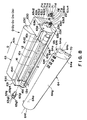
Figure 8 is an exploded perspective view of a
developing cartridge wherein a shutter part is broken.
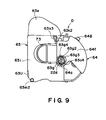
Figure 9 is a side view of a non-driving side
of the developing cartridge wherein the shutter is
closed.
Figure 10 is a side view of a driving side of
a developing cartridge wherein the shutter is closed.
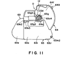
Figure 11 is a side view of a non-driving
side of a developing cartridge wherein the shutter is
opening.
Figure 12 is a side view of a driving side of
a developing cartridge wherein the shutter is opening.
Figure 13 is a perspective view of a non-driving
side of a developing cartridge mounting
portion of a rotary unit.
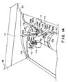
Figure 14 is a perspective view of a driving
side of a developing cartridge mounting portion of a
rotary unit.
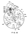
Figure 15 is a side view illustrating a
mounting operation of a developing cartridge onto a
rotary unit.
Figure 16 is a side view illustrating a
mounting operation of a developing cartridge onto a
rotary unit.
Figure 17 is a side view illustrating a
mounting operation of a developing cartridge onto a
rotary unit.
Figure 18 is a side view illustrating a
mounting operation of a developing cartridge onto a
rotary unit.
Figure 19 is a side view illustrating a
mounting operation of a developing cartridge onto a
rotary unit.
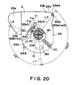
Figure 20 is a side view illustrating a
relation between a guide of the developing cartridge
and a positioning member.
Figure 21 is a top plan view illustrating a
showing of the driving device.
Figure 22 is a side view of a driving device
for the developing cartridge.
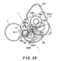
Figure 23 is a side view showing a preferable
arrangement of a driving member of a developing
cartridge.
Figure 24 is a side view showing a preferable
arrangement of a driving member of a developing
cartridge.
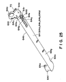
Figure 25 is a perspective view of a shutter.
Figure 26 is top plan view illustrating
mounting of a rotary unit of a developing cartridge.
Figure 27 is a perspective view of a
developing member supporting frame
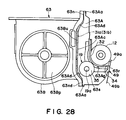
Figure 28 is a side view of a developing
member supporting frame.
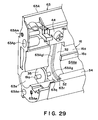
Figure 29 is a perspective view of an end of
developing member supporting frame.
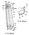
Figure 30 is an illustration of a toner
frame, wherein (a) is a perspective view of a toner
frame and (b) is a cross-sectional view of a toner
frame.
Figure 31 is a horizontal sectional view of a
toner frame.
Figure 32 is a perspective view of a non-driving
side of a developing cartridge as seen
inclinedly from the bottom.
Figure 33 is a side view of a longitudinal
end portion of a developing cartridge.
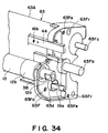
Figure 34 is a perspective view of a coupling
frame portion of a developing cartridge.
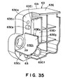
Figure 35 is a perspective view of a non-driving
side cover.
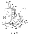
Figure 36 is a perspective view of a
remaining toner amount detecting means.
Figure 37 is a partial enlarged view of the
remaining toner amount detecting means of Figure 36.
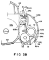
Figure 38 is a longitudinal sectional view
wherein the shutter is closed.
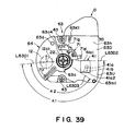
Figure 39 is a side view of a driving side
cover.
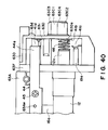
Figure 40 is a front view of an end with the
shutter of the developing cartridge being removed.
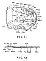
Figure 41 is a perspective view of an inside
of the driving side cover.
Figure 42 is a sectional view taken along a
line B-B of Figure 39.
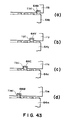
Figure 43 ((a), (b), (c), (d)) is schematic
top plan views of a developing cartridge
discriminating means.
Figure 44 is a side view of driving means of
a developing cartridge.
Figure 45 is a perspective view of a
cartridge frame.
DESCRIPTION OF THE PREFERRED EMBODIMENTS
Embodiments
Next, the development cartridge in the
preferred embodiment of the present invention, and an
electrophotographic image forming apparatus
(hereinafter, image forming apparatus) compatible with
this development cartridge, will be described.
In the following description, "longitudinal
direction" means such a direction that is
approximately perpendicular to the direction in which
recording medium is conveyed, and also that is
approximately parallel to the surface of the recording
medium being conveyed.
Embodiment 1
First, referring to Figures 1 - 9, the first
embodiment of the present invention will be described.
Figures 1 - 3 are schematic drawings which depict the
structure of an image forming apparatus; Figures 4 -
5, sections of a development cartridge; Figures 6 - 7,
perspective views of the development cartridge; and
Figures 8 - 14 are schematic drawings which depict the
structure of the development cartridge. It should be
noted here that in Figures 2, 3, and 15 - 19, dotted
lines are used as imaginary lines.
In describing the present invention, the
overall structure of the image forming apparatus will
be first described, and then, the structure of the
development cartridge will be described.
(Image Forming Apparatus)
First, the general structure of the image
forming apparatus in accordance with this embodiment
will be described. Figure 1 is a side view of a color
laser beam printer, a typical form of an image forming
apparatus which forms a color image, with the use of
an electrophotographic system. In this apparatus, the
peripheral surface of an electrophotographic
photosensitive member 1 (hereinafter, photosensitive
drum) in the form of a drum, which rotates at a
predetermined constant speed, is uniformly charged by
a charging means 2. Then, a laser beam modulated with
image data is projected from an exposing means 3 onto
the charged peripheral surface of the photosensitive
drum 1. As a result, a latent image is formed on the
peripheral surface of the photosensitive drum 1. The
latent image is developed with the use of one of four
development cartridges Dm, Dc, Dy and Db, which will
be collectively designated by a letter D. The
developed image on the photosensitive drum 1 is
sequentially transferred, in a superposing manner,
onto an intermediary transfer unit 4 in the form of a
belt. As a result, a full-color image is formed on
the intermediary transfer unit 4. Then, the full-color
image is transferred by a transferring means 6
onto a recording medium P (for example, a sheet of
recording paper, an OHP sheet, and the like) which is
conveyed from a recording medium feeding section by a
conveying means 5. Thereafter, the recording medium P
is conveyed to a fixing means 7, which permanently
fixes the full-color image to the recording medium P,
and discharges the recording medium P into a delivery
section 8 located on the top side of the image forming
apparatus.
Next, the structure of each section of the
image forming apparatus will be described more
specifically.
The photosensitive drum 1 is an integral part
of a process cartridge U, and is supported by a
container-like frame 9a of a cleaning means 9 for
removing the toner remaining on the photosensitive
drum 1 after an image composed of developer
(hereinafter, "toner") is transferred onto the
intermediary transfer unit 4. The process cartridge U
is removably installed in the main assembly 30 of the
image forming apparatus, and is replaceable by an
ordinary user alone; it is replaced as the service
life of the photosensitive drum 1 expires.
The photosensitive drum 1 comprises an
aluminum cylinder with a diameter of approximately 50
mm, and a layer of organic photosensitive material
coated on the peripheral surface of the aluminum
cylinder. It is rotatively supported by the
container-like frame 9a of the cleaning means 9 that
doubles as the holder for the photosensitive drum 1.
In contact with the peripheral surface of the
photosensitive drum 1, a cleaning blade 9b for
scraping off the toner remaining on the peripheral
surface of the photosensitive drum 1, and the charging
means 2, are disposed. In other words, in this
embodiment, the photosensitive drum 1, the cleaning
means 9, and the charging means 2, are integrated in
the form of a cartridge, that is, the process
cartridge U, removably installable in the apparatus
main assembly 30.
The photosensitive drum 1 is rotated in the
counterclockwise direction in Figure 1 in synchronism
with an image forming operation by the driving force
transmitted to the photosensitive drum 1 from a motor
24M (Figure 21).
The charging means 2 in this embodiment is
such a charging means that uses a so-called contact
type charging method. Thus, the peripheral surface of
the photosensitive drum 1 is uniformly charged by
applying voltage to an electrically conductive charge
roller, as a charging member, which is being rotated
in contact with the peripheral surface of the
photosensitive drum 1.
The exposing means 3 exposes the charged
peripheral surface of the photosensitive drum 1. More
specifically, as image signals are given to an
unillustrated laser diode, the diode projects an image
forming light modulated with the image signals onto a
polygon mirror 3a, which is being rotated at a high
velocity by a scanner motor 3b. The image forming
light deflected by the mirror 3a is projected through
an image forming lens 3c, is deflected by a deflection
mirror 3d, and then, selectively exposes the
peripheral surface of the photosensitive drum 1, which
is rotating at a predetermined constant velocity. As
a result, an electrostatic latent image is formed on
the peripheral surface of the photosensitive drum 1.
The latent image is developed by the
development cartridge D (developing apparatus) into a
toner image of specific color. The structure of the
development cartridge D will be described later.
The toner image formed by the development
cartridge D is transferred onto the intermediary
transfer unit 4. The intermediary transfer unit 4, as
the second image bearing member, is such a unit that
transfers all at once (second transfer) the plurality
of toner images having been transferred (first
transfer) onto the intermediary transfer unit 4, onto
the recording medium P. The intermediary transfer
unit 4 comprises an intermediary transfer belt 4a
which is run in the direction of an arrow mark R4.
The intermediary transfer belt 4a in this embodiment
is a belt with a circumference of approximately 440
mm, being suspended around three rollers: a driving
roller 4b, a second transfer roller 4c, and a
following roller 4d. The intermediary transfer unit 4
also comprises a pressing roller 4j, which takes two
positions; a position where the pressing roller 4j
keeps the intermediary transfer belt 4a pressed upon
the photosensitive drum 1, and a position where the
pressing roller 4j allows the intermediary transfer
belt 4a to keep a short distance away from the
photosensitive drum 1. The intermediary transfer belt
4a is run in the arrow R4 direction by the rotation of
the driving roller 4b. Further, the intermediary
transfer unit 4 comprises a cleaning unit 4e, which is
disposed at predetermined location outside the loop of
intermediary transfer belt 4a. The cleaning unit 4e
can be placed in contact with the outward surface of
the intermediary transfer belt 4a, or can be moved
away from the intermediary transfer belt 4a. The
cleaning unit 4e removes the waste toner which is
remaining on the intermediary transfer belt 4a after
the toner images on the intermediary transfer belt 4a
are transferred all at once (second transfer) onto the
recording medium P. The cleaning unit 4e comprises a
charging roller 4f, which is placed in contact with
the intermediary transfer belt 4a to charge the toner,
which is remaining on the intermediary transfer belt
4a, to the polarity opposite to the polarity to which
the toner is charged during the image transfer onto
the recording medium P. The reversely charged toner
is electrostatically adhered to the photosensitive
drum 1, and then, is recovered by a cleaning apparatus
for cleaning the photosensitive drum 1. The cleaning
apparatus 9 will be described later. The method for
cleaning the intermediary transfer belt 4a does not
need to be limited to the above described
electrostatic cleaning method; a mechanism method
which use a blade or a fur brush, a combination of the
electrostatic and mechanical methods, and the like may
be also used.
The toner which is remaining on the
peripheral surface of the photosensitive drum 1 after
the toner images are transferred onto the intermediary
transfer unit 4 is removed by the cleaning means 9;
the toner is scraped into a toner bin 9c by a cleaning
blade 9b, as a cleaning member, placed in contact with
the peripheral surface of the photosensitive drum 1.
The toner scraped into the toner bin 9c is accumulated
therein. The toner bin 9c is constituted of a part of
the frame 9a of the cleaning means 9, and is given a
capacity large enough so that it will not be filled up
with the toner before the service life of the
photosensitive drum 1 expires. Thus, the toner within
the toner bin 9c is disposed all at once as the
process cartridge is replaced at the end of the
service life of the photosensitive drum 1.
In this embodiment, the transferring means 6
for transferring the toner images, which have been
transferred onto the intermediary transfer unit 4 in a
superposing manner, onto the recording medium P is
constituted of a transfer roller 6 as an image
transfer member. The transfer roller 6 comprises a
metallic shaft, and a layer of foamed elastic material
with electrical resistance in a medium range wrapped
around the peripheral surface of the metallic shaft.
It is rendered movable in the vertical direction in
Figure 1.
While four color toner images are transferred
onto the intermediary transfer unit 4, that is, while
the intermediary transfer unit 4 is rotated a
plurality of times, the transfer roller 6 is placed at
the bottom position outlined by a solid line in Figure
1, being separated from the intermediary transfer unit
4, so that the toner images are prevented from being
disturbed by the transfer roller 6.
After the toner images are transferred onto
the intermediary transfer unit 4 in a superposing
manner, that is, after a full-color toner image is
formed on the intermediary transfer unit 4, the
transfer roller 6 is moved to the top position
outlined by a single dot chain line in Figure 1, by an
unillustrated cam, in synchronism with the timing with
which the full-color toner image is transferred onto
the recording medium P. As the transfer roller 6 is
moved to the top position, it is pressed upon the
intermediary transfer unit 4, pinching the recording
medium P between itself and the intermediary transfer
unit 4. At the same time as the transfer roller 6 is
moved to the top position, bias voltage begins to be
applied to the transfer roller 6, and as a result, the
full-color toner image on the intermediary transfer
unit 4 is transferred onto the recording medium P.
Referring to Figure 1, the conveying means 5
for conveying the recording medium P comprises: a
sheet feeding cassette 5a for storing a plurality of
recording medium P; a pickup roller 5b; a combination
of a feeding roller 5cl and a retarding roller 5c2 for
preventing two or more sheets of recording medium P
from being fed at the same time; a conveying roller
pair 5d; a registering roller pair 5e; a discharging
roller pair 5f; and a conveying guide 5g.
In an image forming operation, the pickup
roller 5b is rotatively driven in accordance with the
image forming operation to feed out, one by one, the
recording medium P in the sheet feeding cassette 5a.
The recording medium P having fed out of the sheet
feeding cassette 5a is guided by the conveying guide
5g, and is conveyed farther by the conveying roller
pair 5d to the registering roller pair 5g. The
registering roller pair 5e is activated according to a
predetermined rotational image sequence that comprises
a period in which the registering roller pair 5e is
stopped to keep the recording medium P on standby, or
stationary, and a period in which the registering
roller pair 5e is rotated to convey the recording
medium P toward the intermediary transfer unit 4, so
that the full-color image and the recording medium P
is properly aligned in the following process, that is,
the transferring process. Then, the full-color toner
image is transferred onto the recording medium P by
the transferring means.
The recording medium P on which the full-color
toner image has been transferred is conveyed to
the fixing means 7, by which the full-color toner
image is fixed. The fixing means 7 comprises a fixing
roller 7a for applying heat to the recording medium P,
and a pressing roller 7b for pressing the recording
medium P onto the fixing roller 7a. Both rollers 7a
and 7b are hollow and contain a heater. They are
rotatively driven. They fix the full-color toner
image to the recording medium P by conveying the
recording medium P while applying heat and pressure to
the recording medium P.
Thereafter, the recording medium P on which
the full-color toner image has been fixed is
discharged into the delivery section 8 by the
discharging roller pair 5f which constitutes the
conveying means.
(Development Cartridge - Developing Apparatus)
Next, the structure of a development
cartridge for developing a latent image formed on the
aforementioned photosensitive drum 1 will be
described.
In order to form a full-color image, the
image forming apparatus in this embodiment comprises
four development cartridge D (Dm, Dc, Dy and Db) for
developing four colors: magenta, cyan, yellow, and
black. Referring to Figures 1 - 3, the development
cartridges D are removably fitted in a rotary unit 11
which is rotated about an central shaft 10. In an
image forming operation, the development cartridges D
circularly move about the central shaft 10, being held
by the rotary unit 11. The rotary unit 11 is stopped
as a development cartridge D which contains a color
toner to be immediately used arrives at a position
where the development cartridge squarely faces the
photosensitive drum 1, that is, the position where the
distance between the development cartridge D and the
photosensitive drum 1 is microscopic (approximately
300 µm). At this position, the toner is supplied to
the peripheral surface of the photosensitive drum 1 in
a manner to reflect the electrostatic latent image on
the photosensitive drum 1; the latent image is
5 developed.
In an image forming operation, for each
rotation of the intermediary transfer unit 4, the
rotary unit 11 also rotate once, so that the magenta
development cartridge Dm which contains magenta color
toner, the cyan development cartridge Dc which
contains cyan color toner, the yellow development
cartridge Dy which contains yellow color toner, and
the black development cartridge Db which contains
black color toner, carry out a development process, in
5 the same order as they are listed. It should be noted
here that the black color tone is a magnetic toner,
and the other color toners are nonmagnetic toners.
Figure 4 depicts a development cartridge D
(for example, the yellow development cartridge Dy),
which is stopped at the development position where the
development cartridge D squarely faces the
photosensitive drum 1. The development cartridge D
comprises a development roller 12 as an image
developing member, that is, a toner carrying member
5 for supplying the photosensitive drum 1 with toner,
and a toner storing portion 63a for storing the toner
to be supplied to the development roller 12. The
development cartridge D also comprises a cartridge
frame 63 and a shutter 64. The cartridge frame 63 is
constituted of a plurality of subframes, and supports
the development roller 12. The shutter 64 covers or
exposes the opening cut in the cartridge frame 63. In
the toner storing portion 63a, a toner conveying
member 15 is disposed. A brand-new development
cartridge is sealed with a toner seal 27 to prevent
the toner stored in the toner storing portion 63a from
leaking. Thus, before installing a brand-new
development cartridge D into the apparatus main
assembly 30, an operator is required to peel the toner
seal 27 to unseal the toner storing portion 63a, so
that the toner in the toner storing portion 63a is
enabled to be supplied to the development roller 12.
The toner conveying member 15 rotates by
receiving driving force from the apparatus main
assembly 30, to deliver the toner in the toner storing
portion 63a to the development roller 12. The
development roller 12 is a rotatable aluminum roller,
and a development blade 16 is placed in contact with
the peripheral surface of the development roller 12.
Thus, as the development roller 12 is rotated in the
clockwise direction in Figure 4, a thin layer of toner
is coated on the peripheral surface of the development
roller 12. While the toner is coated, it is
triboelectrically charged.
A toner image which reflects the latent image
on the photosensitive drum 1 can be formed on the
photosensitive drum 1 by applying development bias
supplied from the apparatus main assembly 30, to the
development roller 12 placed in a manner to squarely
face the photosensitive drum 1, on which the latent
image has been formed.
As each development cartridge D is moved to
the development position, the development roller 12 in
the development cartridge D is connected to a high
voltage power source and a mechanical power source,
which are provided on the main assembly side. As a
result, development bias voltage specific to each
development cartridge D is selectively applied to the
development cartridge D, and the mechanical driving
force is transmitted to the development roller 12 and
the like, rotating them.
The magenta development cartridge Dm, the
cyan development cartridge Dc, and the yellow
development cartridge Dy, which are depicted in Figure
4, are the same in structure. All of these color
development cartridges Dm, Dc and Dy comprise a
coating roller 19. At the interface between the
coating roller 19 and the development roller 12, the
peripheral surface of the coating roller 19 moves in
the direction opposite to the direction in which the
peripheral surface of the development roller 12 moves.
The coating roller 19 is rotatively supported by the
development frame 63A of the cartridge frame 63.
The black development cartridge Db
illustrated in Figure 5 does not have a coating
roller. The black toner adheres to the development
roller 12 due to its own adhesive force, and due to
the magnetic force of a magnet (unillustrated)
disposed inside the development roller 12. The
thickness of the layer of the toner, which has adhered
to the development roller 12, is regulated by the
development blade 16 placed in contact with the
peripheral surface of the development roller 12. As
the thickness of the toner layer is regulated by the
development blade 16, the toner becomes
triboelectrically charged. As described before, in
the development cartridges Dm, Dc and Dy, the
development roller 12 does not contain a magnet. This
is because the black toner in this embodiment is a
magnetic toner, whereas the magenta, cyan and yellow
toners are nonmagnetic toners.
(Installation of Development Cartridge into Main
Assembly of Image Forming Apparatus)
Next, the structure for installing the
development cartridge D into the main assembly 30 of
an image forming apparatus will be described.
Referring to Figures 1, 13 and 14, the apparatus main
assembly 13 is provided with a development cartridge
opening 17, which is located at a predetermined
position in the apparatus main assembly 30, and the
width of which is greater than the dimension of the
development cartridge D in the longitudinal direction.
To the edge of the opening 17, a cover 18 is pivotally
attached to expose or cover the opening 17. Normally,
the development cartridge opening 17 is covered with
the cover 18.
The apparatus main assembly 30 is provided
with a development apparatus replacement switch
(unillustrated), which is to be pressed when the
development cartridge D needs to be replaced because
of toner depletion of the like. As the switch is
depressed by an operator, the rotary unit 11 rotates
about the central shaft 10, by which the rotary unit
11 is supported, until one of the color development
cartridges D to be replaced arrives at the development
cartridge opening 17.
Referring to Figure 14, as the cover 18 is
opened by the operator, a guide 59 is exposed, which
constitutes means for installing the development
cartridge D. There are four guides 59 at a lateral
end of the rotary unit 11, equally dividing the rotary
unit 11 in the circumference direction of the rotary
unit 11. Next, referring to Figures 6, 7, 8 and 10,
the shutter 64 of the development cartridge D is
provided with a guide portion 70, which is slid along
the guide 59 by the operator to insert the development
cartridge D into the apparatus main assembly 30. It
should be noted here that the guide portion 70 is
provided on only one of the longitudinal ends of the
development cartridge D (ends in the terms of the
axial direction of the development roller 12), and
therefore, the guide 59 is provided also on only one
of the two lateral walls, that is, the longitudinal
end lateral wall lla of the rotary unit 11. The
lateral walls lla and lle are provided with arc-shaped
ribs 59e and 26a, respectively, and the longitudinal
end walls of the development cartridge D are provided
with projections 63c and 63g that fit in the space
surrounded by the arc-shaped ribs 59e and 26a,
respectively.
When installing the development cartridge D
in the rotary unit 11, the operator grasps the
handhold portion 63e (Figure 7) of the development
cartridge D by hand, and inserts the development
cartridge D into the rotary unit 11 in the direction
perpendicular to the longitudinal direction of the
development roller 12, with the development roller 12
facing forward (development roller 12 facing in such a
direction that it faces the photosensitive drum 1
after installation of the development cartridge D).
Then, after the shutter 64 of the development
cartridge D is immovably locked with the apparatus
main assembly 30, the operator rotates the development
cartridge D about the projections 63c and 63g. As a
result, the shutter 64 is opened, and the development
roller 12 is exposed from the cartridge frame 63 in a
manner to directly and squarely face the
photosensitive drum 1, being readied for image
development.
The other lateral wall lle of the rotary unit
11 is provided with a semispherical pressing member
26b, which is surrounded by the arc-like ribs 26a of
the guide 26, and elastically presses the development
cartridge D in the longitudinal direction of the
development cartridge D after the development
cartridge D is installed in the rotary unit 11
(development cartridge D is elastically pressed toward
a driving force receiving member 22). More
specifically, the pressing member 26b is under elastic
pressure generated by a spring in the longitudinal
direction. Therefore, the development cartridge D is
elastically pressed toward the longitudinal end (of
the development cartridge D) to which driving force is
transmitted. In other words, in installing the
development cartridge D in the rotary unit 11
(apparatus main assembly 30), the driving force
receiving member side of the development cartridge D
is used as the reference point in terms of the
longitudinal direction.
Here, referring to Figures 8 - 12, the
structure of the development cartridge D will be
described in detail. Figure 8 is a perspective view
of the development cartridge D, from which the shutter
64 and the components belonging to the shutter 64 have
been removed. Figures 9 and 10 are side views of the
development cartridge D, at the opposing longitudinal
ends, with the shutter 64 closed. The Figures 11 and
12 are side views of the development cartridge D, at
the opposing longitudinal ends, with the shutter 64
open.
Referring to Figure 8, the cartridge frame 63
of the development cartridge D is provided with an
opening 63b, which extends in the longitudinal
direction of the cartridge frame 63. The development
roller 12 is attached to the cartridge frame 63 in
such a manner that the development roller 12 is
exposed through the opening 63b. Further, the
cartridge frame 63 is provided with a projection 63c,
which is integrally formed with the cartridge frame
63, and projects outward from the approximate center
of a longitudinal end wall 63h of the cartridge frame
63. The projection 63 acts as a guide when the
development cartridge D is inserted into the apparatus
main assembly 30, and also acts as a rotational axis
when the development cartridge D is installed, or
removed from, the apparatus main assembly 30. The
projection 63c is in the form of a cylinder, and will
be described later in more detail.
The development cartridge D comprises a
projection 63g, which is removably attached to the
approximate center of the longitudinal end wall 63i of
the cartridge frame 63, that is, the counterpart of
the wall 63h (Figure 8 depicts the projection 63g
which has been removed from the cartridge frame 63).
More specifically, the projection 63g is attached to
the cartridge frame 63 by inserting the anchoring
portion 63g1 of the projection 63g into the hole
(unillustrated) cut through the longitudinal end wall
63i. The anchoring portion 63g1 is provided with a
latching portion (unillustrated), which is located at
the tip of the anchoring portion 63g1, and the
projection 63g is attached to the cartridge frame 63
by engaging this latching portion of the anchoring
portion 63gl with the cartridge frame 63. As the
development cartridge D is installed into the
development cartridge space of the rotary unit 11, the
other end of the projection 63g2, that is, the end
opposite to the anchoring portion 63gl, of the
projection 63g comes in contact with the
aforementioned pressing member 26b, which is
elastically projecting from the longitudinal end wall
11a of the rotary unit 11. Therefore, the development
cartridge D comes under the pressure from the pressing
member 26b, being pressed toward the longitudinal end
wall 63h of the development cartridge D (in the
direction of an arrow mark Q in Figure 8). In other
words, the development cartridge D is accurately
placed in the rotary unit 11 (apparatus main assembly
30), using the longitudinal end wall 63h of the
development cartridge D, that is, the driving force
receiving side of the development cartridge, as the
reference point.
The longitudinal ends of the development
roller 12 are fitted with spacer rings 12a and 12b,
one for one. Therefore, when the development roller
12 is at the development position, the spacer rings
are pressed upon the peripheral surface of the
photosensitive drum 1 by an elastic pressure applying
member 25 (Figure 24), or by the elastic pressure of a
compression spring 10b (Figure 3) which elastically
presses or sliding member 10a. As a result, a
predetermined gap is maintained between the
development roller 12 and photosensitive drum 1.
The development blade 16 formed of rubber or
the like is attached to the cartridge frame 63, by
attaching the metallic plate 16a of the development
blade 16 to the cartridge frame 63 with a small screw
16b. The structure of the development blade 16 will
be described later in detail.
To the longitudinal end wall 63h of the
development cartridge D, a locking member 71 is
attached (Figure 8 depicts it as being separated from
the wall 63h). The locking member 71 comprises: a
latching portion 71b which engages with a latching
portion catching recess 64t of the side wall 64e of
the shutter 64; a support portion 71a for supporting
the latching portion 71b; and anchoring portions 71c
and 71d, with which the locking member 71 is attached
to the longitudinal end wall 63h of the cartridge
frame 63. Referential codes 63j1 and 63j2 are holes
cut through the wall 63h, and the anchoring portions
71c and 71d are engaged in these holes, respectively.
The locking member 71 is formed of plastic material,
and is molded in a single piece. In the process of
inserting the development cartridge D in the
development cartridge space of the rotary unit 11, the
arm portion 71g, that is, a portion of the locking
member 71, comes in contact with a solid projection of
the apparatus main assembly 30. As the development
cartridge D is farther inserted, the supporting
portion 71a is elastically bent, and as a result, the
latching portion 71b is disengaged from the latching
portion catching recess 64t, that is, the shutter 64
is unlocked.
Next, referring to Figures 2, 3, 6, 8, 10 and
12, the semispherical projection 63d, which comes in
contact with one of the longitudinal ends of the
development cartridge D, is provided on only the
longitudinal end wall 63h of the cartridge frame 63.
Accordingly, the shutter 64 is provided with a hole
64u, in which the projection 63d engages, and which is
located so as to align with the projection 63d when
the development cartridge D is in the rotary unit 11.
Thus, when the shutter 64 is in the closed state, the
projection 63d is in engagement with the hole 64u, and
therefore, even if the shutter 64 is released from the
locking member 71, the cartridge frame 63 does not
unexpectedly rotate.
Further, the longitudinal end walls 63h and
63i comprise attitude controlling boss 63m (63m1,
63m2), and spring contacting portions 63k (63k1,
63k2), respectively, which project outward from the
walls.
Referring to Figure 9, a referential figure
73 designates a toner seal removal handle, which is
used by an operator to pull out the aforementioned
toner seal 27.
(Shutter)
Next, the shutter 64 will be described.
Referring to Figure 25, the longitudinal end
walls 67e and 64f of the shutter 64 are provided with
a round hole 64a, in which the projections 63c and 63g
are engaged, one for one, so that the shutter 64 is
rotatably attached to the cartridge frame 63. Next,
referring to Figures 6 and 7, as the shutter 64 is
closed, the opening 63b is covered; the development
roller 12 is covered by the shutter 64. When the
development cartridge D is out of the apparatus main
assembly 30, the shutter 64 is closed. Therefore,
dust or the like does not adhere to the development
roller 12; the development roller 12 or the like is
not damaged; and foreign objects do not enter the
development cartridge D.
The supporting portion 71a of the locking
member 71 is shaped in the form of a cantilever, being
therefore rendered elastically bendable, by providing
the locking member 71 with a groove 71f. The base end
of the supporting portion 71a in the form of a
cantilever is the side where the anchoring portions
71c and 71d are located. The latching portion 71b and
the lock releasing arm 71g are located at the
extending end portion of the supporting portion 71a.
The anchoring portion 71c is cylindrical, extending in
the longitudinal direction of the development
cartridge D, and fits in the hole 63jl. The two
anchoring portions 71d located adjacent to the
anchoring portion 71c have a square cross section,
extending in the longitudinal direction of the
development cartridge D. They each are provided with
the aforementioned latching claw (unillustrated). The
locking member 71 is locked with the longitudinal end
wall 63h of the cartridge frame 63 by engaging the
anchoring portions 71d in the square holes 63j2 cut
adjacent to the hole 63j1.
Referring to Figure 12, when the shutter 64
is open, the tip of the latching portion 71b is in
contact with the edge portion of a cam 64n in the form
of an arc that is concentric with the hole 64a of the
side wall 64e of the shutter 64. As the shutter 64 is
closed, the latching portion 71b engages in the
latching portion catching recess 64t of the edge
portion 64n of the cam of the shutter 64, whereby the
shutter 64 is locked shut, being prevented from
unexpectedly opening.
As the development cartridge D is inserted
into the apparatus main assembly 30, the latching
portion 71b is automatically disengaged from the
recess 64t, and at the same time, the shutter 64 is
opened.
(Installation and Removal of Development Cartridge)
Next, referring to Figures 13 - 19, steps for
installing the development cartridge D into the
apparatus main assembly 30, and steps for properly
positioning the development cartridge D in the
apparatus main assembly 30, will be described in
detail.
First, referring to Figure 14, the inwardly
facing surface of the longitudinal end wall 11a of the
rotary unit 11 is provided with the guide 59, which
comprises: an entrance portion 59b between the slanted
ribs 59a which are slanted so that the distances
between them are greater at the top than at the
bottom; a projection guiding portion 59d between
approximately parallel straight ribs 59c; a projection
accommodating portion 59f, as the development
cartridge supporting portion, between the arc-shaped
ribs 59e; a guide accommodating portion 59h between
the approximately parallel straight ribs 59g
continuous from the arc-shaped ribs 59e. The inwardly
facing surface of the longitudinal end wall 11e, that
is, the counterpart of the wall 11a, is provided with
the guide 26.
Next, referring to Figures 13 and 14, each
longitudinal end of the central shaft 10 that supports
the rotary unit 11 is fitted with the sliding member
10a, which is placed adjacent to the inwardly facing
surface 11e of the longitudinal end flange 11f of the
rotary unit 11 (and also, inwardly facing surface 11a
of the longitudinal end flange 11g of the rotary unit
11) when the development cartridge D is in the rotary
unit 11. Moving to Figure 15, the sliding member 10a
is symmetrical relative to the line drawn through the
center of the central shaft 10 of the rotary unit 11
and the center of the arc-shaped ribs 59e, and is
slidably coupled with a guide portion 10d, the center
line of the cross section of which is parallel to the
aforementioned line. Further, the sliding portion 10a
is provided with a hole 10a1, which extends in
parallel to the guide portion 10d, that is, in the
longitudinal direction of the central shaft 10, and
the cross section of which is in the form of an
elongated circle. In this hole 10a1, a pin shaft 10c
fixed to the central shaft 10 is fitted, allowing the
sliding member 10a to take two positions: a position
at which the arcing peripheral surface 10e of the
sliding member 10a becomes continuous with the
peripheral surface of the central shaft 10a, forming a
cylindrical surface, as illustrated in Figure 15, and
another position to which the sliding member 10a
retracts to provide the central shaft 10 with a recess
10f, the bottom of which is constituted of the arcing
peripheral surface of the sliding member 10a, as shown
in Figure 18. Between the bottom surface of the guide
portion 10d and the inward end of the sliding member
10a, a compression spring 10b is placed in the
compressed state. The width of the arcing peripheral
surface 10e of the sliding member 10a (distance
between one straight edge of the arcing peripheral
surface of the sliding member to the other, measured
in a straight line which is parallel to Figure 18, and
perpendicular to the aforementioned straight line
drawn through the centers of the central shaft 10 and
the arc-shaped ribs 59e) is such that when the
development cartridge D is in the development
cartridge space of the rotary unit 11, the development
cartridge attitude controlling bosses 63m (63m1, 63m2)
contact the arcing peripheral surface of the sliding
member 10a.
When installing the development cartridge D
into the apparatus main assembly 30, the user first
inserts the development cartridge D, while allowing
the sliding guide portion 70 and the projection 63c of
the shutter 64 to be guided by the entrance portion
59b of the guide 59 (Figure 15).
As the development cartridge D is farther
inserted, the projection 63c located at one of the
longitudinal ends of the development cartridge D
enters the straight portion of the projection guiding
portion 59d between the straight ribs 59c as
illustrated in Figure 16. The projection 63c
comprises a cut portion 63c1, the peripheral surface.
of which is constituted of two parallel flat surface,
and two arcing surfaces located between the flat
surfaces. The distance (width W1 in Figure 14)
between the two straight ribs 59c is such that the
projection 63c is allowed to be guided through the
projection guiding portion 59d only when the
projection 63c is positioned so that the flat surfaces
of the cut portion 63c1 become parallel to the
straight ribs 59c. Therefore, the projection 63c is
guided through the projection guiding portion 59d,
with the cut portion 63cl flatly engaged with the
straight ribs 59c, causing thereby the development
cartridge D to hold a predetermined angle (attitude)
as it is inserted into the apparatus main assembly 30.
Next, referring to Figure 17, as the
projection 63c is inserted as far as the arc-shaped
ribs 59e, the tip of one of the two slanted ribs 59a
comes in contact with the arm portion 71g of the
locking member 71 that is locking the shutter 64, and
pushes up the arm portion 71g as illustrated in Figure
17. As a result, the supporting portion 71a is
elastically deformed and causes the latching portion
71b to slip out of the latching portion catching
recess 64t of the shutter 64; the shutter 64 is
unlocked (in this embodiment, the slanted portion 59a
doubles as a locking member disengaging member). The
unlocked shutter 64 is rotatable relative to the
cartridge frame 63. The arc-shaped ribs 59e have such
a radius that allows the projection 63c to freely
rotate, and therefore, the development cartridge D
becomes rotatable about the projection 63c.
On the other hand, the projection 63g
provided on the other longitudinal end wall 63i of the
development cartridge D enters the entrance portion of
the guide 26, being guided by the slanted portion 26c
of the guide 26 illustrated in Figure 13. As the
development cartridge D is farther inserted, the cut
portion 63g3 of the projection 63g enters between the
two parallel straight ribs 26e, with the two flat
peripheral surfaces of the cut portion 63g3 flatly
engaging with the surfaces of the correspondent
straight ribs 26e, causing thereby the development
cartridge D to hold a predetermined angle (attitude)
as it is inserted into the apparatus main assembly 30.
The development cartridge D is inserted until the
projection 63g engages with the arc-shaped ribs 26a
(projection supporting ribs). The arc-shaped ribs 26a
have such a radius that allows the projection 63g to
rotate as it is supported by the arc-shaped ribs 26a.
In other words, one of the longitudinal ends of the
cartridge frame 63 is supported by the arc-shaped ribs
59e, as the supporting members, of the guide 52, with
the projection 63c being supported by the ribs 59e,
and the other is supported by the arc-shaped ribs 26a,
as the supporting members, of the guide 26, with the
projection 63g being supported by the arc-shaped ribs
26a. Thus, the development cartridge D is supported
by the rotary unit 11 so as to be rotatable about the
projections 63c and 63g.
The structure for installing, without a
mistake, the development cartridge Dm, Dc, Dy and Db
in the cartridge installation spaces 14m, 14c, 14y and
14b of the rotary unit 11, will be described later.
Next, as the user pushes, by hand, the
handhold portion 63e of the cartridge frame 63 in the
state illustrated in Figure 17, the cartridge frame
63, the projections 63c and 63g of which are supported
by the arc-shaped ribs 59e and 26a, respectively,
rotate, although shutter 64 is still locked because
the guide portion 70 is still in the guide
accommodating portion 59h. Then, as the cartridge
frame 63 rotates, the semispherical projection 63d
comes out of the hole 64u of the shutter 64 and moves
to a predetermined point (direction indicated by an
arrow mark X in Figure 17). As described before, in
this embodiment, the shutter 64 is provided with the
insertion guide portion 70, and therefore, the
cartridge frame 63 can be easily rotated while keeping
the shutter nonrotatable. Then, as the semispherical
projection arrives at the predetermined point, the
carriage frame 63 is locked by the positioning means,
which will be described later. In other words, the
development cartridge D has been successfully
installed.
Further, as the development cartridge D in
the state illustrated in Figure 17 is rotated in the
arrow X direction, the cartridge attitude controlling
bosses 63m (63m1 and 63m2) provided on the
longitudinal end walls 63h and 63i of the cartridge
frame 63 push the sliding member 10a down, which is
slidably coupled in the guide portion 10d deep enough
to reach across the rotational axis of the central
shaft 10, and which is being pressed outwardly by the
compression spring 10b (Figure 18). As described
before, the sliding member 10a has the hole 10a1,
which extends through the sliding member 10a in
parallel to the guide portion 10d, and the cross
section of which is in the form of an elongated
circle. And, the pin shaft 10c fixed to the central
shaft 10 is put through this hole 10a1. Therefore,
the sliding member 10a is slidable only in a limited
range. In other words, the sliding member 10a is
allowed to slide outward as far as a point at which
the pin shaft 10c makes contact with the outward side
of the hole 10a1. Also as described before, when the
sliding member 10a is at this outward point, the
arcing outward peripheral surface of the sliding
member 10a forms a continuous surface with the
peripheral surface of the central shaft 10. Next, as
the cartridge frame 63 is farther rotated, the spring
contacting portion 63k provided on the longitudinal
end walls 63h and 63i of the cartridge frame 63, one
for one, are pressed by the springs lld provided on
both longitudinal ends of the rotary unit 11, one for
one. As a result, the cartridge frame 63 is subjected
to such force that works in the direction to rotate
the cartridge frame 63 in the direction indicated by
an arrow mark Y (Figure 19). However, since both
attitude controlling bosses 63m remain in contact with
the sliding member 10a coupled with the central shaft
10 of the rotary unit 11, the attitude of the
cartridge frame 63 becomes stabilized as the cartridge
frame 63 is rotated to the angle illustrated in Figure
19.
In other words, the development cartridge D
has been successfully installed in the predetermined
position in the rotary unit 11.
A referential code 11j designates a guide
portion provided on the rotary unit 11. It guides the
boss 63m.
Through the steps described above, the
shutter 64 is rotated relative to the cartridge frame
63, that is, the shutter 64 is opened, exposing the
development roller 12 so that the development roller
12 is allowed to directly face the photosensitive drum
1. The point at which the operator should begin to
rotate the development cartridge D during the
installation of the development cartridge D is
recognizable by the operator because a sensation of
clicking is generated when the semispherical
projection 63d comes out of the hole 64u of the
shutter 64.
The diameter of the cylindrical portion 63c2
of the projection 63c is greater than the distance
between the two parallel flat peripheral surfaces of
the cut portion 63c1, and therefore, once the
projection 63c is supported by the arc-shaped ribs
59e, the projection 63c does not come out through the
gap between the straight ribs 59c while it is
rotating.
Similarly, the diameter of the cylindrical
portion 63g4 of the projection 63g on the other end of
the development cartridge D is greater than the
distance between the two parallel flat peripheral
surfaces of the cut portion 63g3, and therefore, once
the projection 63g is supported by the arc-shaped ribs
26a, the projection 63g does not come out through the
gap between the straight ribs 26e while it is
rotating.
On the other hand, in order to remove the
development cartridge D from the apparatus main
assembly 30, the cartridge frame 63 must be rotated in
the direction opposite to the installing direction, by
the operator. As the development cartridge D is
reversely rotated, the flat peripheral surfaces of the
cut portion 63cl become parallel to the straight ribs
59c, and the shutter 64 closes. As the shutter 64
closes, the semispherical projection 63d engages with
the hole 64u, and as the projection 63d engages with
the hole 64u, the aforementioned clicking is felt by
the operator, and therefore, the operator can
recognize that the development cartridge D has been
rotated to the final position (installation-removal
position). Then, the operator pulls out the
development cartridge D from the apparatus main
assembly 30. As the operator pulls out the
development cartridge D, the supporting portion 71a of
the locking member 71 elastically returns to the
locking position as illustrated in Figure 16, causing
the latching portion 71b to engage with the latching
portion catching recess 64t; in other words, the
shutter 64 is automatically locked.
With the provision of the development
cartridge D with the shutter 64 structured as
described above, it is possible to prevent dust or the
like from adhering to the development roller 12.
Further, since the shutter 64 is provided with the
locking mechanism, the shutter 64 is prevented from
unexpectedly opening.
The shutter 64 remains closed while the
development cartridge D is inserted into the apparatus
main assembly 30, and therefore, the development
roller 12 is not damaged during the insertion.
Further, the operator is not required to remove the
development roller protecting members or the like from
the development cartridge D by hand before inserting
the development cartridge D.
Further, during the insertion of the
development cartridge D into the apparatus main
assembly 30, the shutter lock is automatically
unlocked, and also, after insertion, as the
development cartridge D is rotated, the shutter 64 is
automatically opened to allow the development roller
12 to directly face the photosensitive drum 1 to
complete the installation. Therefore, the
installation of the development cartridge D becomes
more efficient.
(Positioning of Development Cartridge)
Next, the positioning of the development
cartridge D will be described.
First, referring to Figure 20, the
positioning of the spring contacting portion 63k (63k1
and 63k2) as the member for bearing the spring
pressure, and the positioning of the development
cartridge attitude controlling bosses 63m (63m1 and
63m2) as the pushing members, will be described.
In the following description, the structures
of the cartridge frame 63 at the longitudinal ends
will be described with reference to the longitudinal
end with wall 63h, and the same description applies to
the longitudinal end with the wall 63i.
In this embodiment, as seen from the
longitudinal direction of the development roller 12,
the spring contacting portion 63k is positioned in a
range from approximately 100 deg. to 130 deg. from the
straight line drawn through the rotational center M2
of the development roller 12 and the rotational center
M1 of the driving force receiving member 22, measured
about the rotational center M1.
More specifically, as seen from the
longitudinal direction of the development roller 12,
the spring contacting portion 63k1 (63k2) is
positioned so that the angle between the straight line
L1 drawn through the rotational center M2 of the
development roller 12 and the rotational center M1 of
the driving force receiving member 22, and the
straight line L2 drawing through the spring force
receiving surface 63k3 (which aligns with the radial
direction of the driving force receiving member 22) of
the spring contacting portion 63k1 (63k2), becomes
approximately 100 deg. to 130 deg. The actual angle
in this embodiment is approximately 115 deg.
The boss 63m (63m1 and 63m2) is positioned
approximately 130 deg. to 150 deg. away from the
straight line L1 in the direction opposite to the
direction of the spring force receiving portion 63k1
(63k2).
More specifically, the boss 63m is positioned
so that the angle between straight line L1 and the
straight line L3 drawn through the center 63m3 of the
boss 63m and the rotational center M1 falls in an
approximate range of 130 deg. to 150 deg. The actual
angle in this embodiment is approximately 140 deg.
With the positioning of the spring force
receiving portion 63k (63k1, 63k2) and the boss 63m
(63m1, 63m2) as described above, the spring contacting
portion 63k is enabled to desirably bear the elastic
force of the compression spring 11d provided on the
rotary unit 11 of the apparatus main assembly 30. In
addition, the boss 63m is enabled to desirably contact
the sliding member 10a coupled with the central shaft
10. Therefore, the development cartridge D can be
precisely positioned in the development cartridge
space.
The boss 63m (63m1, 63m2) is projected
outwardly from the side surface 63h or 63i of the
cartridge frame 63 by approx. 2 mm - 15 mm. In this
embodiment, the boss 63m is projected by approx. 4 mm.
The spring receptor portion 63k (63k1, 63k2)
is projection outwardly from the side surface 63h, 63i
of the cartridge frame 63 by approx. 2 mm- 20 mm. In
this embodiment, the spring receptor portion 63kl is
projected by approx. 10 mm, and 63k2 is projected by
approx. 6 mm. In other words, the projection height
of the spring receptor portion 63kl provided at the
driving force reception side is larger.
(Driver of the Developing Cartridge)
The description will be made as to a drive
transmission structure for transmission from the main
assembly of the apparatus to the developing cartridge
D.
As shown in Figures 21, 22 and 44, one of
projections which is cylindrical (projected portion
63c), of the projected portions 63c, 63g of the both
side surfaces 63h, 63i at the longitudinal opposite
ends of the cartridge frame 63, has therein a driving
force receiving member 22 for transmitting rotation
driving force from the main assembly 30 to the
developing roller 12. The driving force receiving
member 22 has an integrally molded stepped driving
gear 23a. A large gear 23a1 of the gear 23a is in
meshing engagement with the developing roller gear 23b
mounted to the rotation shaft 12c of the developing
roller 12, and the developing roller 12 is rotated
when the driving force is transmitted to the driving
force receiving member 22. A small gear 23a2 of the
gear 23a is in meshing engagement with a stirring gear
23d which is integrally molded with a journal 33
(Figure 31) which is a rotation shaft of the toner
feeding member 15 through the stepped idler gear 23c
so as to transmit the rotating force also to the toner
feeding member 15. An application roller gear 23e
fixed on the rotation shaft 19a of the application
roller 19 is in meshing engagement with a small gear
23a2 integral with the driving force receiving member
22.
The free end portion of the driving force
receiving member 22 has a cross-shaped rib functioning
as a coupling member 22d, which is couplable with a
drive transmission member of the main assembly 30
which will be described hereinafter.
On the other hand, as shown in Figure 21, the
rotary unit 11 in the main assembly 30 of the image
forming apparatus is provided with a drive
transmission member 24, coaxial with and opposed to
the driving force receiving member 22 when the
developing cartridge D is mounted in place, for
transmitting driving force from a motor 24M. The
transmitting mechanism for transmitting the driving
force to the drive transmission member 24 from the
motor 24M is schematically shown by chain lines. The
drive transmission member 24, as shown by a in Figure
21, is movable in the axial direction of the driving
force receiving member 22, and the end portion thereof
is formed into a coupling configuration engageable
with the rib of the driving force receiving member 22.
Here, the coupling configuration means the shape with
which the driving force receiving portion 22 and the
drive transmission member 24 are coupled when the
drive transmission member 24 is moved relative to the
driving force receiving portion 22, and when one of
them rotates, the other also rotates. In this
embodiment, the driving force receiving member 22 is
provided with four recesses 22a, and the drive
transmission member 24 has four projections 24a. The
driving force receiving member 22 is rotated by the
rotation of the drive transmission member 24 while the
recesses 22a and the projections 24a are engaged.
When the developing cartridge D mounted in
place is moved to the developing position for image
formation by rotation of the rotary unit 11, the drive
transmission member 24 is moved toward the driving
force receiving member 22 by the moving mechanism
(unshown), and is engaged with the driving force
receiving member 22 to transmit the driving force to
the developing roller 12 or the like. Thus, even if
the stop position of the developing cartridge D
relative to the photosensitive drum 1 is more or less
deviated, or the generating lines of the
photosensitive drum 1 and the rotary unit 11 are more
or less deviated, the driving force only by the
coupling is transmitted at the constant position to
developing cartridge D, and therefore, it is possible
to reduce the pitch non-uniformity due to gear meshing
defect.
Referring to Figures 23 and 24, the structure
for stabilizing the pressure of the developing roller
12 to the photosensitive drum 1, will be described.
The same reference numerals as in Figure 22 are
assigned to the elements having the corresponding
functions, and detailed descriptions thereof are
omitted for simplicity.
As described in the foregoing, the rotating
force is transmitted to the driving force receiving
member 22 of the developing cartridge D from the drive
transmission member 24 of the main assembly 30 at the
development position.
In Figure 23, the developing cartridge D is
at the developing position.
At this time, a line X1 connecting a center
of rotation of the developing cartridge D which is the
center of the projected portion 63c of the developing
cartridge D and the center of rotation of the
photosensitive drum 1, and a line X2 connecting a
center of rotation of the projected portion 63c and a
center of rotation of the developing roller 12,
satisfy that line X2 is upstream of the line X1 with
respect to a driving rotational direction R of the
driving force receiving member 22 as seen from a
rotational center of the projected portion 63c.
With this structure, the developing cartridge
D receives rotation moment in the direction R so that
developing roller 12 is urged normally toward the
photosensitive drum 1, and therefore, the development
operation of the developing roller 12 is stabilized.
This is advantageous in a so-called contact
development, but is particularly advantageous in the
case of non-contact development since a gap between
the photosensitive drum 1 and the developing roller 12
is stabilized.
As shown in Figure 24, there may be provided
urging means 25 movable in the direction indicated by
the arrow to fix the developing cartridge D by urging
it toward the photosensitive drum 1 when the
developing cartridge D is at the developing position.
In such case, a direction DM of moment produced in the
developing cartridge D by the urging action of the
urging means 25, the line X1 connecting a center of
rotation of the developing cartridge D (said projected
portion 63c) and a center of rotation of the
photosensitive drum 1, and the line X2 connecting the
center of rotation of the projected portion 63c and
the center of rotation of the developing roller 12,
may satisfy that line X2 is upstream of the line X1
with respect to the direction DM of the moment as seen
from the center of rotation of the projected portion
63c, since the same effects are provided. Here, the
urging means 25 is provided at each of the
longitudinal ends of the developing cartridge D to
urge the rear surface portion of the toner
accommodating portion 63a.
(Erroneous Mounting Prevention Means of the Developing
Cartridge)
The developing cartridges D (Dm, Dc, Dy, Db)
have the mounting portions which are the same in the
configurations, dimensions or the like, and are
mountable to any of the cartridge mounting portions of
the rotary unit 11. By providing means for preventing
the user from mounting an improper developing
cartridge to any one of the cartridge mounting portion
of the rotary unit 11, the operativity is improved.
As shown in Figures 2, 3, 13, 14, the rotary unit 11
has a disk-like flanges llf, llg at the opposite ends
thereof, and the center of the flange is supported by
shaft means 10. The cartridge mounting portions 14
are disposed in the rotary unit 11 equidistantly in
the circumferential direction. More particularly,
four cartridge mounting portions 14 are provided
equidistantly, and are to receive developing
cartridges Dm, Dc, Dy, Db respectively ( cartridge
mounting portions 14m, 14c, 14y, 14b).
Separation plates 11m, 11c, 11y, 11b are
extended between the flanges 11f, 11g to divide into
the cartridge mounting portions 14, and the flanges
11f, 11g are connected with each other thereby. The
separation plates 11m, 11c, 11y, 11b, are extended in
the axial direction of the rotary unit 11 in the
section shown in Figures 2, 3. The separation plates
11m, 11c, 11y, 11b are provided with main assembly
discriminating portions 11m1, 11c1, 11y1, 11b1 at an
end adjacent the flange 11g (flange 11g side). In
Figures 2, 3, the rotary unit 11 is shown in a cross-section
at the position of the discriminating portion
llcl, and the discriminating portions 11m1, 11y1, 11b1
are not seen in the Figures, since the discriminating
portions 11m1, 11c1, 11y1, 11b1 are longitudinally
different positions of the rotary unit 11. The
discriminating portions 11m1, 11c1, 11y1, 11b1 have
the same configurations, and are in the form of
recesses at an outer edge of each of the separation
plate 11m, 11c, 11y, 11b.
On the other hand, as shown in Figures 25,
43, the shutter 64 (64m, 64c, 64y, 64b) of the
developing cartridge D is provided with a cartridge
discriminating portion 64M, 64C, 64Y or 64B for
distinguishing the developing cartridges D (Figures 2,
3, 25 indicate discriminating portion 64B). The
discriminating portions 64M, 64C, 64Y, 64B are
disposed at longitudinally different positions on the
outer periphery of the cylindrical portions of the
shutter 64 of the developing cartridge D. The
discriminating portions 64M, 64C, 64Y, 64B are in the
form of projections extending from the outer periphery
of the shutter 64. The centers of the discriminating
portions 64M, 64C, 64Y, 64B are on a line
substantially passing through the center of the round
hole 64a and perpendicular to a guide 70 which is in
the form of a linear rib extending toward the center
of the round hole 64a provided in the shutter 64, as
seen in the longitudinal direction of the shutter 64.
The discriminating portions 64M, 64C, 64Y, 64B are
concentrated at an open end 64h of the shutter 64
faced to the developing roller 12 and adjacent the
driving force reception side in the longitudinal
direction.
As shown in Figure 25, the shutter 64 has
four seats 64s arranged at equal intervals in the
longitudinal direction, to which blocks 64r are
mountable to establish the discriminating portions
64M, 64C, 64Y, 64B. The seat 64s has block
positioning holes 64p, 64q spaced in the
circumferential direction of the shutter 64. The hole
64p is a round hole, and the hole 64q is elongated
hole elongated in the circumferential direction of the
shutter 64. The block 64r is substantially cubic and
is provided, on a side which is not seen in Figure 25
and which is opposed to a side opposing to the seat
64s, with projections engageable with the holes 64p,
64q. By engagement therebetween, the block 64r is
correctly positioned and is fixed by bonding material.
The block 64r is mounted to one of the four
seats 64s to provide a discriminating portion 64M,
64C, 64Y or 64B of the developing cartridge D. When
the developing cartridge D provided with the
discriminating portion 64M, 64C, 64Y or 64B is mounted
to the mounting portion 14m, 14c, 14y, 14b, the
discriminating portion 64M, 64C, 64Y, 64B of the
developing cartridge D is engaged with the
discriminating portion 11m1, 11c1, 11y1, 11b1 of the
cartridge mounting portion 14, so that it may be
permitted to enter the cartridge mounting portion 14m,
14c, 14y or 14b. However, to the cartridge mounting
portion 14y, for example, any one of the developing
cartridges Dm, Dc, Db is not mountable because any one
of the discriminating portions 64M, 64C, 64B abuts the
edge without the discriminating portion 11y1 of the
separation plate lly.
Similarly, the cartridge mounting portion 14m
for the magenta color developing cartridge Dm rejects
any one of the developing cartridges Dy, Dc, Db by the
cartridge mounting portion 14m. The cartridge
mounting portion 14c for the cyan color developing
cartridge Dc rejects any one of the developing
cartridges Dy, Dm, Db. The cartridge mounting portion
for the black toner developing cartridge Db rejects
any one of the developing cartridges Dy, Dm, Dc.
Figures 2, 26 show the state in which the
developing cartridge Dc is in the process of being
mounted to the cartridge mounting portion 14c. When
the developing cartridge Dc is mounted to the
cartridge mounting portion 14c, the linear guide
portion 70 of the developing cartridge Dc is inserted
into a guide inserting portion 59h of the cartridge
mounting portion 14c so that shutter 64 enters the
cartridge mounting portion 14c in the linear
direction, and simultaneously, the developing
cartridge Dc makes a translational motion in the
lateral direction. It reaches a position where the
pose determining boss 63m of the developing cartridge
Dc can enter the guide portion 11j provided in the
wall surface 11a of the driving side flange llg of the
rotary unit 11. The discriminating portion 64C
provided in the shutter 64 comes close to the edge 11x
of the separation plate 11c, but the edge 11x is
provided with a discriminating portion 11c1 (recess)
which permits only the discriminating portion 64C to
enter, and therefore, the projected portion 63c of the
developing cartridge Dc engages with the engaging
portion 59f of the rotary unit 11, and the
discriminating portion 11c1, 64C are engaged. The boss
63m enters the guide portion 11j, so that positions
are now shown in Figures 2, 17, 26. When the
cartridge frame 63 is rotated clockwisely in Figure 2,
the cyan developing cartridge Dc accommodating the
cyan toner is mounted to the cartridge mounting
portion 14c of the rotary unit 11 in the manner
described in the foregoing, as shown in Figure 3.
When the developing cartridge Dm, Dy, Db
accommodating a color toner other than the cyan toner
is going to be mounted to the cartridge mounting
portion 14c for the cyan developing cartridge Dc, the
leading end of the guide portion 70 of the developing
cartridge Dm, Dy, Db can enter the guide inserting
portion 59h, but when the leading end of the guide
portion 70 reaches a position 13 shown in Figure 2,
the discriminating portion 64M, 64Y, 64B of the
developing cartridge Dm, Dy, Db abuts the edge 11x of
the separation plate llc. The developing cartridge Dm,
Dy, Db is unable to go further, and the cutting
portion 63c1 having a width equal to the length
between the opposite sides of the projected portion
63c has already enters the linear rib 59c portion
(Figure 14), and therefore, the developing cartridge
Dm, Dy, Db cannot rotate, either. Therefore, the
developing cartridge Dm, Dy, Db other than the
developing cartridge Dc accommodating the cyan toner
is not mountable to the cartridge mounting portion 14c
of the developing cartridge Dc.
Similarly, the developing cartridge Dm, Dy,
Db are mountable to the cartridge mounting portions
14m, 14y, 14b, respectively, but the other developing
cartridge is not mountable.
The shutter 64 mounted to a developing
cartridge D for developing a latent image formed on
the electrophotographic photosensitive drum 1, which
is detachably mountable to the main assembly 30 of the
electrophotographic image forming apparatus for
forming a multi-color image, is provided with the
guide portion 70, mounted for rotation about a
longitudinal axis relative to the cartridge frame 63
of the developing cartridge D, for guiding it to the
developing cartridge mounting portion 14 of the main
assembly 30 of the image forming apparatus. The
shutter is movable between a covering position for
covering an exposed portion of the developing roller
12 of the cartridge D when it is out of the main
assembly 30 and a retracted position for exposing the
developing roller 12 when the cartridge is mounted to
the cartridge mounting position of the main assembly
30. The shutter 64 includes developing cartridge side
discriminating portions 64M, 64C, 64Y, 64B which
permit the developing cartridge D to enter the
discriminating portion 11m1, 11c1, 11y1, 11b1 of the
main assembly only when they are aligned in position,
at the time when a developing cartridge D is mounted
to any one of the developing cartridge mounting
portions 14 of the main assembly 30 of the image
forming apparatus. When the user mounts the
developing cartridge to the cartridge mounting portion
of the main assembly of the image forming apparatus,
the user is prevented from mounting improper color
developing cartridge to the cartridge mounting
portion.
The developing cartridge side discriminating
portion may have common seats 64s, and the blocks 64r
are selectively mounted thereto, so that there is no
need of preparing different types of shutters 64, and
therefore, the manufacturing cost can be reused.
In the embodiment, the discriminating portion
is shifted to toward the driving force receiving
portion shifting of the developing cartridge, but it
may be changed to another longitudinal position. The
intervals between adjacent discriminating portions may
be irregular. The discriminating portion is in the
form of square projection and recess, but
convex/concave is usable (arcuated shape or v-shaped).
(Structure of Developing Frame)
As shown in Figures 4, 6, 7, the cartridge
frame generally indicated by a reference numeral 63 is
constituted by the developing frame (main cartridge
frame) 63A, the developing frame, the cover frame 63C,
the side covers (developer cartridge side covers) 63D,
63E, and the coupling frame 63F.
As shown in Figure 4, the developing frame
63A and the toner frame 63B are welded together by
ultrasonic welding at a triangular projections on a
connecting surface 63n between the flanges 63Aa
extended along the longitudinal direction at both of
the lateral sides of the developing member supporting
frame 63A and a flange 63Ba extended along the
longitudinal direction of the toner frame 63B.
The toner frame 63B and the cover frame 63C
are coupled so as to face the openings 630 of the
frames, thus constituting a toner container. To
accomplish this flange 63Ba of the toner frame 63B has
a L-shaped cross-section, and the upper surface
thereof functions as a connecting surface 63p, and the
flange 63Bb constitutes the connecting surface 63p and
is formed to enclose the opening 630. The flange 63Cb
enclosing the opening 630 of the cover frame 63C is
welded by ultrasonic welding with the flange 63Bb of
the toner frame 63B at the connecting surface 63p.
As shown in Figures 6, 7 as perspective
views, the opposite longitudinal end portions of the
thus welded developing frame 63A and toner frame 63B
are covered by side covers 63D, 63E, and side cover
63E is screwed to the developing frame 63A, and the
side cover 63D is screwed to the coupling frame 63F
fixed to the developing frame 63A. In this manner,
the frames constitutes an integral cartridge frame 63.
(Developing Frame)
The description will be made referring to
Figures 4, 5, 27 and 28.
The developing frame 63A is projected toward
the opening 63Bc side of the toner frame 63B from the
flange 63Aa extended longitudinally at two lateral
sides. One lateral side of the from side 63Ab of the
projected portion is opposed to a toner seal surface
27a along the length. On the toner seal surface 27a,
the toner seal 27 of the toner frame 63B is stuck, and
the toner seal 27 is stuck on the toner seal surface
27a. The longitudinal surface 63Ab1 (Figure 27) of
the front surface 63Ab of the projected portion, close
to the toner seal 27 on the toner seal surface 27a, is
flush with the surface 63Ab2. The flat surface 63Ab2
is provided along the lateral direction at each of the
longitudinal opposite ends of the toner supply opening
63Ae, and it continues to the flat surface 63Ab2. The
lateral flat surface 63Ab2 extended in the lateral
direction at each of the longitudinal opposite ends of
the front side 63Ab continues to an arcuated surface
63Ab3 concentric with the application roller 19 and
having a radius slightly larger than a radius of the
outer periphery of the application roller 19
immediately outside the application roller 19. The
lateral surfaces 63Ab2, 63Ab3 bent from the opposite
ends of the front side 63Ab of the projected portion
has a narrow width. The longitudinal flat surface
63Ab1 is projected perpendicularly from the flange
63Aa.
End seals 31a, 31b which are elastic members
are stuck on the developing frame 63A away from the
longitudinal opposite sides of the front side 63Ab of
the projected portion. Adjacent a side where the
toner seal 27 is pulled out, a film 31c is stuck on
the inside of the end seal 31a to decrease the
friction with the toner seal 27.
The developing frame 63A has a end seal
sticking surface 63Ac for sticking thereon an end seal
31a and 31b at a position retracted from the surface
63Ab2. At each of the lateral sides of the sticking
surface 63Ac, there is provided an arcuated surface
63Ad. The sticking surface Ac and the flange 63Aa are
smoothly connected by the arcuated surface 63Ad
(Figures 27 and 28). The end seal 31a and 31b is
provided at each of the opposite longitudinal ends of
the toner supply opening 63Ae, along the lateral
direction of the developing frame 63A. The
longitudinally opposite ends of the end seals 31a and
31b, are sandwiched between the flange 63Aa and the
lateral end of the toner frame 63B. Designated by 63n
is a connecting plane where they are welded.
On the other hand, the toner frame 63B is
provided with a seal surface 63Bu for urging the end
seals 31a and 31b stuck on the developing frame 63A
when the developing frame 63A is coupled with the
toner frame 63B (Figure 28).
A toner supply opening 63Ae penetrates the
developing frame 63A. The toner supply opening 63Ae
is extended along the developing roller 12. The
vertical opening region of the toner supply opening
63Ae is narrowed between the cleaning blade 16 and the
sealing member 34. The toner supply opening Ac is
enclosed by the front surface 63Ab, the shaft mounting
portion 63q and the flange 63Aa. The developing
roller 12 is mounted to the developing roller mounting
portion in the longitudinal direction of the toner
supply opening 63Ae (Figure 29).
As described in the foregoing, the developing
frame 63A includes a developing roller 12 for
developing a latent image formed on the photosensitive
drum 1, the toner accommodating portion 63a for
accommodating the toner to be used for development by
the developing roller 12, a toner accommodating
portion 63a for accommodating the toner on the surface
of the developing roller 12, and an application roller
19 for applying the toner on the surface of the
developing roller 12. The developing frame is usable
with a developing cartridge D detachably mountable
relative to the main assembly 30 of the image forming
apparatus. It further includes a toner supply opening
63Ae for supplying to the developing roller 12 the
toner accommodated in the toner accommodating portion
63a, the developing roller mounting portion for
mounting the developing roller 12 along the toner
supply opening, the connecting surface for coupling
with the toner frame 63B having the toner
accommodating portion 63a, the connecting surface 63n
being provided along the longitudinal direction of the
toner supply opening at each of the lateral ends of
the toner supply opening 63Ae, a projection having a
sticking surface 63c, a shaft mounting portion 63q and
a front surface 63Ab, the projection being projected
toward the toner frame 63B in the direction crossing
with a plane connecting the connecting surfaces 63n.
There is provided a shaft mounting portion
63q for mounting a shaft for supporting the
application roller to mount the application roller,
the portion projecting in a direction crossing with a
plane connecting the connecting surfaces (63w) and
mounting the application roller (19) along the toner
supply opening (63Ae), the shaft mounting portion 63q
mounting the shaft at the developing roller (12) side
beyond a plane connecting the connecting surface 63n,
and the shaft mounting portion being provided adjacent
one and the other longitudinal ends of the toner
supply opening (63Ae). The application roller having
a shaft (19a) mounted to said shaft mounting portion
(63q) crosses in its longitudinal direction the plane
connecting said connecting surfaces (63n) provided at
both of the lateral sides of the toner supply opening
(63Ae). The opposite longitudinal end portion are
provided with elastic members (26b) for urging the
toner seal (27) for sealing the toner supply opening
of said toner frame, the mounting surface of the
elastic member is in the form of a projected surface
toward the toner frame beyond a plane connecting the
connecting surface (63n). The leading edge of the
projected surface is a flat surface, and the flat
surface is projected toward the developing frame
beyond the application roller (19). The plane
connecting the mounting surface of the elastic members
(26b) at the opposite longitudinal ends is away from
the application roller (19). The mounting surface of
the elastic member is connected by a curved surface
outside the application roller (19) between the
connecting surface and the leading edge of the
projected surface. The curved surface is an arcuation
having a center which is a center of the application
roller (19).
A side of the mounting surface of the elastic
member (266) opposite from the curved surface is
connected with the connecting surface by an outwardly
convex surface. The toner supply opening (63Ae) is
rectangular as seen from the toner frame and is
provided with an application roller (19) mounting
portion to dispose the application roller along an
edge of one lateral side of the toner supply opening
(63Ae), wherein toner supply opening is defined in a
plane substantially flush with the connecting surface
at one lateral side thereof and is defined in a plane
connecting the mounting surfaces of the elastic member
at longitudinally opposite ends, at the other lateral
end and at the longitudinally opposite ends.
The description will be made as to the
structure of the developing frame 63A at the side
opposite from the side of toner frame 63B with respect
to the connecting surface 63n.
The shaft mounting portion 63q for supporting
the rotation shaft 19a of metal of the application
roller 19, as shown in Figure 4, is molded integrally
with the developing frame 63A, they are provided
adjacent the opposite longitudinal ends of the
developing frame 63A. Bearing holes of the shaft
mounting portion 63q for the rotation shaft 19a is
closer the developing roller 12 than the connecting
surface 63n. Namely, it is at the opposite side of
the toner frame 63B across the flat surface connecting
the connecting surfaces 63n. The black developing
cartridge Db does not has an application roller
(Figures 28 and 29).
The shaft mounting portion 63q has an
arcuated concave surface 63Ag for sticking an elastic
seal member 32 of felt for sealing between the
developing zone and the outside. The arcuated convex
surface 63Ag continues to the flat surface 63Ag1
substantially parallel with the developing blade 16.
The longitudinal end portion of the 16c supported on
the plate 16a is overlapped with an end of the elastic
seal member 32 stuck on the surface. A seal member 34
which is parallel with the elastic blade 16c and which
is close to the peripheral surface of the developing
roller 12, is stuck on the seal mounting surface 63r
of the developing frame 63A.
As shown in Figure 29, a longitudinally outer
portion of the shaft mounting portion 63q for the
application roller 19, is provided a recess 63s having
an arcuation shape section concentric with the
rotation shaft 19a of the application roller 19, and a
shaft gasket 35 in the form of a disk of felt is
engaged with the recess 63s and the rotation shaft
19a. The packing 35 is lightly. press-contacted to the
outer surface of the shaft mounting portion 63q by the
cylindrical projected portion 63Df, 63Ff (Figure 35,
45) provided in each of the coupling frame 63F and the
side cover 63D entering the recess 63s of the
developing frame 63A, to eject the sealing. This is
the same as the other longitudinally opposite ends.
The foregoing is the structure of the
developing frame 63A of the developing cartridge D
accommodating the magenta, cyan or yellow toner. In
the case of a developing cartridge Db accommodating
the black toner does not have the application roller,
and therefore, the space accommodating the application
roller, the mounting portion for the rotation shaft of
the application roller, the space for the shaft
sealing of the rotation shaft mounted to the mounting
portion or the like are not provided. As shown in
Figure 5, the bottom surface 63t of the developing
frame 63A below the developing roller 12 constitutes a
substantially horizontal surface extended below the
developing roller 12 at the developing position where
the developing roller is opposed to the photosensitive
drum 1.
As shown in Figure 27, one of the
longitudinal end surface of the developing frame 63A
is provided with coupling frame 63F. The other end
surface is provided with seats 63Ak1, 63Ak2 for
mounting a side cover 63E at the toner seal pulling
side. The seats have the same configurations. Each
of the seats 63k1, 63k2 is provided with screw 63Am
and positioning holes 63An, 63Ap. The hole 63An is a
round hole, and the hole 63Ap is elongated in a
direction connecting the holes 63An, 63Ap.
By the structures of the developing frame as
above-described, the developing cartridge can be
downsized. Or, a larger amount of the toner can be
accommodated if the size of the developing cartridge
is the same.
(Toner frame)
As shown in Figure 4, the connecting surface
63n of the toner frame 63B with respect to the
developing member supporting frame 63A and the
connecting surface 63p of the toner frame 63B with the
cover frame 63C are substantially perpendicular to
each other.
As shown in Figures 30 (a perspective view of
the toner frame) and 31, a bearing portion 63Be
provided in an end plate 63Bd at one longitudinal end
of the toner frame 63B, rotatably supports the journal
33 integral with a gear 23d. The other longitudinal
end of the toner frame 63B is provided with a
cylindrical toner supply opening 63Bp, and a bearing
portion 63Be at the center thereof rotatably supports
the journal 36. The bearing portion 63Be is connected
to the toner supply opening 63Bp by a radial arm 63Bs
from the bearing portion 63Be, and is integrally
molded with the toner frame 63B. To the journals 33,
36., a toner feeding member 15 (toner stirring member)
on the shaft 15c is fixed. The toner feeding member
15 is extended substantially over the entire length of
the toner frame 63B, and the opposite ends are out of
the developing zone. At the same side as the toner
cap 37 fixed to the toner supply opening 63Bp and
outside the developing zone, there are provided first,
second openings 63Bf and 63Bg, as shown in Figure 4.
In to the first and second openings 63Bf, 63Bg, light- transmissive
members 81, 82 of synthetic resin
material for example are securely engaged. The light
introduced through the first opening 63Bf passes
through the second opening 63Bg when the amount of the
toner is small in the toner frame 63B. As shown in
Figure 4, 5 and 32, the shutter 64 is provided with an
opening 64k for passing the emergent light through the
second opening 63Bg.
The light- transmissive members 81, 82 of the
toner frame 63B respectively have a cylindrical
surface 81a and a flat surface 82a which an elastic
blade 15a (cleaning member) of synthetic resin
material mounted to the plate 15b close to the center
of the toner feeding member 15 rubs or scrapes with
elasticity with interference with the trace of the
motion of the elastic blade 15a. The cylindrical
surface 81a has its center which is a center of
rotation of the toner feeding member 15, and the flat
surface 82a is perpendicular to the normal line from
the center to a center of the flat surface 82a.
A developing cartridge for developing a
latent image formed on the photosensitive member,
wherein said developing cartridge is detachably
mountable to a main assembly of an electrophotographic
image forming apparatus, said developing cartridge
comprising;
In the longitudinal direction of the
developing roller 12 as said developing member, the
first light-transmissive member 81 and second light-transmissive
member are disposed outside a developing
zone where said developing roller 12 carries out a
developing function.
The developing cartridge D further comprises
a shutter 64 for covering a portion exposed through
said cartridge frame, and said shutter has an opening
64k at a position where it is opposed to said second
light-transmissive member when said shutter is
positioned at an opening position.
The first light-transmissive member is
concave toward inside of the toner accommodating
portion 63a.
The second light-transmissive member is
substantially flat in shape.
The developing cartridge D has an urged
portion 63U urged by an urging member (e.g.
compression coil spring 10b of the urging means 25)
provided in the main assembly 30 of the apparatus when
the developing cartridge D is mounted to the main
assembly 30.
The developing cartridge D has a cleaning
portion (e.g. elastic blade 15a) for removing the
toner deposited on the inner surfaces of the first
light-transmissive member and the second light-transmissive
member.
The developing cartridge D has a toner
feeding member 15 for feeding, toward the developing
member 12, the toner accommodated in the toner
accommodating portion 63a, wherein the toner feeding
member 15 is extended in a longitudinal direction of
the toner accommodating portion 63a.
The cleaning portion (15a) is provided at an
one longitudinal end of the toner feeding member 15.
The cleaning portion (15a) is mounted on a shaft 15c
on which said toner feeding member 15 is mounted, and
said cleaning portion (15a) and said toner feeding
member 15 rotate integrally.
In a direction crossing with the shaft 15c,
the length of the cleaning portion (15a) is longer
than the length of the toner feeding member 15. By
this, the toner deposited on the inner surface of the
light-transmissive member can be removed assuredly.
Thus, in the developing cartridge of the
embodiment, the light- transmissive members 81, 82 are
disposed adjacent a longitudinal end of the developing
roller 12, opposite from the end adjacent which the
driving force receiving member 22 and the developing
bias contact 41 are provided. Therefore, the inside
space of the developing cartridge can be effectively
utilized. And, the space in the main assembly of the
apparatus can be effectively utilized. This is
because the light emitting element 83 and the light
receiving element 86 can be disposed at the opposite
side where the drive transmission member 24 and the
developing bias contact pin 42 are disposed, in the
main assembly 30 of the apparatus. Since the light- transmissive
members 81, 82 are provided adjacent the
longitudinally opposite end of developing roller 12 so
that length of the light guide can be saved.
In this embodiment, the developing zone where
the developing roller 12 carries out the developing
function is a region X (Figure 8) between the end
seals 16dl, 16d2 contacted to the peripheral surface
of the developing roller 12 adjacent one and the other
end thereof, where the toner is deposited on the
roller peripheral surface. The seals 16dl, 16d2 are
to prevent the leakage of the toner outwardly in the
longitudinal direction of the roller 12. In this
specification, the developing zone (X in Figure 8)
where the developing member (developing roller)
carries out the developing function is the region
where the toner contributable to the development of
the electrostatic latent image formed on the
electrophotographic photosensitive member is
deposited, in the longitudinal direction of the
developing member.
In this embodiment, the toner feeding member
15 and the elastic blade 16c (cleaning portion) are of
resin material and are integrally molded. The toner
feeding member 15 and the elastic blade 16c are
provided on the same shaft 15c. Therefore, the toner
feeding member 15 and the elastic blade 16 can be
rotated through one driving mechanism.
The toner feeding member and the cleaning
portion may be separate members, which are mounted on
different shafts. In this case, the driving forces
are transmitted to them respectively.
In this embodiment, the first, second light-transmissive
members are disposed outside the
developing zone in the longitudinal direction of the
developing roller, and therefore, the rotation of the
cleaning portion does not adversely affect the
developing function.
(Cover Frame)
As described in the foregoing, the cover
frame 63C has flanges 63Aa, 63Ba for coupling the
developing member supporting frame 63A and the toner
frame 63B, and the flange 63Aa, 63Ba being offset
toward the developing roller 12 beyond the toner seal
surface 27a. Therefore, as shown in Figure 4, the
front wall 63Cd of the cover frame 63C can be made
closer to the developing frame 63A so that distance
between the front wall 63Cd and the later wall 63Ce
can be made larger. Therefore, inside volume provided
by the toner frame 63B and the cover frame 63C, for
accommodation the toner, can be increased.
(Coupling Frame)
As shown in Figure 34 (perspective view), to
the seat 63kl (Figure 33) at the driving force
reception side end of the developing frame 63A, the
coupling frame 63F is fixed by threading unshown small
screws through the holes 63Fa into the screws 63Am at
the end surface of the developing member supporting
frame 63A. By this, the seat 63Akl at the driving
force reception side of the developing member
supporting frame 63A and the flat mounting surface
63Fk of the coupling frame 63F shown in Figure 45 are
contacted to each other. The configuration of the
mounting surface 63Fk of the coupling frame 63F has
substantially the complementary configuration with the
seat 63Akl of the developing frame 63A so that they
are closely nested. The mounting surface 63Fk is
provided with a longitudinal cylindrical dowels 63Fg
engageable with the positioning holes 63An, 63Ap of
the seat 63Akl of the developing frame 63A.
As shown in Figure 34, one end of the
rotation shaft 12c of the developing roller 12 is
supported on a developing roller bearing 38 engaged
into the coupling frame 63F. The projected shaft 63Fb
supporting the driving force receiving member 22 is
integrally molded with the coupling frame 63F. A
projected shaft 63Fc rotatably supporting stepped an
idler gear 23c including a small gear 23c2 engaged
with the gear 23d integral with a journal 33
supporting the toner feeding member 15, is integrally
provided. There is provided a hole 63Fd through which
the rotation shaft 19a of the application roller 19 is
penetrated. The coupling frame 63F is provided with a
screw 63Fe for mounting the side cover 63D.
The description will be made as to a support
at the other end of the developing roller 12 and a
toner seal 27.
(Side Cover at the Non-driving Side)
As shown in Figure 35, a side cover 63E
provided at the opposite side from the driving side
has a configuration covering the longitudinal end
surfaces of the toner frame 63B and the developing
frame 63A. There is a flat mounting surface 63Ea
contacted to the side cover mounting seat 63Ak2 at the
longitudinal end surface of developing frame 63A, the
mounting surface 63Ea is provided with a cylindrical
dowel 63Eb extending in the longitudinal direction and
engageable with the positioning holes 63An, 63Ap of
the seat 63Ak2 of the developing frame 63A. At the
position aligned with the female screw 63Am of the
developing frame 63A, a hole 63Ec is formed in the
longitudinal direction to fix the side cover 63E to
the developing member supporting frame 63A by
threading an unshown small screw into the screw 63Am
through the hole 63Ec. A developing roller bearing 39
is provided in a hole of the side cover 63E to
rotatably support the rotation shaft 12c of the
developing roller 12 with the side cover 63E being
mounted to the developing frame 63A.
From the mounting surface 63Ea, a cylindrical
projected portion 63Ef is projected in the
longitudinal direction, and the free end of the
projection 63Ef presses the shaft gasket 35 of the
rotation shaft 19a of the application roller 19 to the
shaft mounting portion 63Aq of the rotation shaft 19a
of the application roller 19 of the developing frame
63A. A cover portion 63Eg for covering the outer
periphery of the projected end of the rotation shaft
12c of the developing roller 12. The cover portion
64Eg has an inner surface 63Eh which is the same as
the seal surface of the elastic seal member 32 shown
in Figure 29 (perspective view of the end portion of
the application roller), when mounted, it is flush
with the seal surface.
The side cover 63E is provided with a toner
seal opening 63Ei which extends in the longitudinal.
direction and through which an end of the toner seal
27 is penetrated to allow the toner seal 27 to be
pulled out of the developing cartridge D. The toner
seal opening 63Ei is rectangular, having a long side
along the lateral direction of the toner seal 27, and
the length of the vertical side of the toner seal
opening 63Ei thereof in Figure 35 is larger than the
width of the toner seal pulling grip 73 (Figure 9).
Figure 31 is a horizontal sectional view of
the toner frame 63B including the toner supply opening
63Bc. The toner seal 27 is stuck on the entire
circumference of the edge of the toner supply opening
63Bc, and then turned at the portion 27b, and is
overlaid on the toner seal portion stuck on the entire
circumference of the edge of the toner supply opening
63Bc, and the end 27c thereof is bonded to the toner
seal pulling grip 73. The end 27c of the toner seal
27 and the grip 73 are in the toner seal opening 63Ei,
and is extended out of the developing cartridge D.
As shown in Figure 31, the inside of the toner
seal opening 63Ei is provided with a toner seal
discharging inclined surface 63Ej. The inclined
surface 63Ej is a flat surface and is inclined toward
the toner frame side. Therefore, the toner seal 27,
as shown in Figure 31, is pulled out along the
inclined surface 63Ej inclinedly upwardly from the
toner frame 63B (the side having the toner supply
opening 63Bp). The side cover 63E has a flat surface
63Ek parallel with the sticking surface 63B for the
toner seal at an outside in the pulling direction, the
sticking surface continues from the inclined surface
63Ej. The inclined toner seal discharging surface
63Ej is not limited to the flat surface, but may be a
quadratic surface having a generating line crossing
with the toner seal 27.
When the grip 73 is pulled outwardly, the
toner seal 27 is pulled outwardly through the toner
seal opening 63Ei so that folded or turned portion 27b
moves to the left in Figure 31, and the toner seal 27
is peeled off the edge of the toner supply opening
63Bc from the turned portion 27b. By completely
pulling out the toner seal 27, the toner supply
opening 63Bc is fully opened. By doing so, the toner
in the toner frame 63B can be supplied to the
developer chamber 63At of the developing member
supporting frame 63A. When the toner seal 27 is
pulled out, it is stretched between the corner 63Bm
sealed by the end seal 31a of the toner frame 63B and
the corner portion 63Em formed by the flat surface
63Ek and the inclined toner seal discharging surface
63Ej which is the inner wall of the toner seal opening
63Ei of the side cover 63E. Therefore, the toner seal
27 which is folded back at the front side of the toner
seal supply opening 63Bc, is stretched along the toner
seal surface at the edge of the opening 63Bc. Thus,
it is gradually peeled off at the folded portion 27b
in one direction from the folded portion to the end
seal 31a. Therefore, the direction in which the user
pulls the toner seal 27 through the toner seal opening
63Ei of the side cover 63E can be limited, and
therefore, pulling in improper direction (which may
result in the end seal 31a torn or on leakage of the
toner) can be prevented.
By integrally molding the side cover 63E and
the shaft support member for engaging the bearing 39
of the developing roller 12, the number of parts can
be reduced.
(Remaining Toner Amount Detection)
As described in the foregoing with respect to
Figure 4, the toner frame 63B is provided with first
and second openings 63Bf, 63Bg, and the openings 63Bf,
63Bg are hermetically sealed by light- transmissive
members 81, 82. The shutter 64 is provided with an
opening 64k across a line connecting said light- transmissive
members 81, 82 in the state wherein the
shutter 64 is opened to expose the developing roller
12.
The first and second openings 63Bf, 63Bg are
disposed outside of the developing zone of the
developing roller 12 in the longitudinal direction of
the developing roller 12. The cover frame 63C of the
cartridge frame 63 is provided with a grip 63e at the
central portion in the longitudinal direction. The
grip 63e is provided by forming a recess toward the
inside accommodating the toner at the central portion
of the cover frame 63C in the longitudinal direction.
The recess 63el is short in the longitudinal direction
and is formed in the flange 63Cb of the cover frame
63C adjacent the developing frame 63A. A rear portion
of the cover frame 63C remote from the developing
frame 63A is provided with a recess 63e2 having a size
longer than the recess 63el, and by these recesses
63el and 63e2, the grip 63e is provided.
The first opening 63Bf is disposed adjacent
the grip 63e in the circumferential direction of the
developing cartridge D. The second opening 63Bg is
disposed at a side remote from the first opening 63Bf
as seen from the grip 63e.
The light-transmissive member 81 sealing the
first opening 63Bf is projected toward the toner
accommodating portion 63a, and the light-transmissive
member 82 set in the second opening 63Bg has a flat
configuration. They may be made of acrylic resin
material.
Figure 36 shows the state wherein the
developing cartridge D is loaded in the rotary unit
11. As shown in Figure 36, the main assembly 30 of
the apparatus is provided with a light emitting
element 83 such as a light emitting diode emitting
light in the axial direction of the rotary unit 11,
and a light receiving element 86 such as CCD. On the
other hand, an input light guiding member 84 and an
output light guiding member 85 are projected from the
wall surface lle axially through the flange llf of the
rotary unit 11 and are fixed to the flange llf. The
light emitting element 83 and the light receiving
element 86 are faced to the incident surface 84a and
the emergent surface 85a of the light guiding members
84, 85 when the developing cartridge D is positioned
at the mounting-and-demounting position.
When the developing cartridge D is mounted to
the rotary unit 11, the emergent surface 84c of the
input light guiding member 84 is opposed to the
opening 64k of the shutter 64. The direction of the
emergent surface 84c is determined so that light
therefrom travels through the opening 64k, the first
opening 63Bf and the second opening 63Bg of the
shutter 64.
The incident surface 85c of the output light
guiding member 85 is disposed at such a position that
light emergent from the emergent surface 84c of the
input light guiding member 84 travels through the
opening 64k of the shutter 64, the first opening 63Bf
of the toner frame 63B and the second opening 63Bg,
when the developing cartridge D is mounted to the
rotary unit 11.
With this structure, when the toner
accommodating portion 63a contains the toner, the
light emergent from the light emitting element 83 is
blocked by the toner in the toner accommodating
portion 63a in the toner frame 63B, but when the
amount of the toner in the cartridge frame 63 is very
small, the light travels through the input light
guiding member 84, first opening 63Bf into the toner
frame 63B. The light emergent from the light emitting
element 83 of the main assembly 30, is incident on the
incident surface 84a of the input light guiding member
84 of the rotary unit 11; travels through the input
light guiding member 84; reflected by the reflection
surface 84b; is emergent from the emergent surface
84c; travels through the opening 64k, the transparent
member 81 of the developing cartridge D, toner
accommodating portion 63a in the toner frame 63B,
transparent member 82 to the incident surface 85c in
the output light guiding member 85 of the rotary unit
11; reflected by the reflection surface 85b; travels
through the output light guiding member 85; is
emergent from the emergent surface 85a; and is
received by the light receiving element 86 of the main
assembly 30 of the apparatus. The light receiving
element 86 is a CCD or the like, and therefore, it
produces a signal through photoelectric conversion,
and an unshown toner presence/absence detection
circuit in a main assembly 30 discriminates the no-toner
state, and displays the event on a display.
The light guiding members 84, 85 are of
acrylic resin material.
By unifying the light emitting element 85 and
the light receiving element 86 on a common substrate
87, assembling and disassembling operation is easy.
The input light guiding member 84 and the.
output light guiding member 85 are provided in each of
the cartridge mounting portions 14y, 14m, 14c, 14b in
one rotary unit 11.
As shown in Figure 4, the light-transmissive
member 81 has a cylindrical surface 81a having an axis
coincident with the center line (center of rotation of
the toner feeding member 15) of the journals 33, 36
functioning as the supporting shaft 15c and projects
toward inside of the toner accommodating portion 63a.
The flange 81b in the first opening 63Bf is welded or
bonded to the edge of the first opening 63Bf. Thus,
the light-transmissive member 81 is provided with a
recess 81c, and therefore, the light transmitting
portion of the light-transmissive member 81 is not
contaminated or damaged when the developing cartridge
D is handled.
The light-transmissive member 82 has a flat
surface 82a crossing perpendicularly to a normal line
extended from the center of the supporting shaft 15c
(journals 33 and 36) of toner feeding member 15, and
the flange 82b in the opening 63Bg is welded or bonded
to the edge of the opening 63Bg. Since the
transmissive member 82 is provided with a shallow
recess, the transmission surface of the light-transmissive
member 82 is not contaminated or damaged
when the developing cartridge D is handled. The
radius of the toner feeding member 15 is larger than
the length of the normal line extended to the flat
surface 82a or the cylindrical surface 81a faced to
the toner accommodating portion 63a of the light- transmissive
member 81, 82 from the center of rotation
of the toner feeding member 15. The toner frame 63B
includes an inner surface such as an arcuated surface
63Bt along which an elastic blade of the toner feeding
member 15 is slid with the elastic blade being
slightly bent in free state. The radius of the
arcuated surface 63Bt is larger than the length of a
normal line extended from the center of rotation of
the member 15 to the flat surface 82a of the light-transmissive
member 82 or the cylindrical surface 81a
of the light-transmissive member 81.
As shown in Figure 30 ands 31, the end
portions of the journal 33, 36 is provided with axial
slits, into which a blade supporting metal plate 15b
for the toner feeding member 15 is inserted so as to
be supported thereon. Holes into which the free ends
15b1 of the blade supporting metal plate 15b inserted
into the slit snugly fits, are formed at the axes of
the journals 33, 36. The supporting metal plate 15b
is provided with an elongated hole 15b2 elongated in
the longitudinal direction, and longitudinally
elongated grooves 15b3 are formed at the opposite
ends.
With the provision of the elongated holes
15b2 and the elongated grooves 15b3, when the toner
feeding member 15 rotates, thetoner in the toner
accommodating portion 63a is raised, and is fed out
into the developer chamber 63At when the toner feeding
member 15 approaches to the horizontal position. In
this case, the toner fed out, returns to the toner
accommodating portion 63a through the elongated holes
15b2 and the elongated grooves 15b3, so that it can be
avoided that too much toner is fed into the developer
chamber 63At. Additionally, the load of the toner
feeding member 15 can be reduced, so that driving
power for the developing cartridge D can be reduced.
To the blade supporting metal plate 15b, the
elastic blade 15a is bonded or welded to constitute an
integral unit. The light- transmissive members 81, 82
are slightly projected into the toner accommodating
portion 63a beyond the arcuated surface 63Bt of the
toner frame 63B. On the other hand, the free end of
the elastic blade 15a is away from the center of
rotation by the same distance over the entire length
thereof, and therefore, the elastic blade 15a is bent
more in the positions of the cylindrical surface 81a
of the light-transmissive member 81 and the flat
surface 82a of the light-transmissive member 82 than
in the other longitudinal positions. By this, the
toner is assuredly removed from the cylindrical
surface 81a and the flat surface 82a. Thus, the
correctness of the detection of the presence or
absence of the toner in the toner accommodating
portion 63a is maintained.
In order to assure the correctness of the
detection of the presence or absence of the toner in
the toner accommodating portion 63a, a part, in the
longitudinal direction, of the elastic blade 15a
(toner stirring member) is flexed more than the other
portion to assuredly remove the toner deposited on the
inner surfaces of the light- transmissive members 81,
82. To avoid the influence to the development, the
light- transmissive members 81, 82 are located adjacent
the longitudinal end portion of the toner
accommodating portion 63a, which is outside the
developing zone, so that motion of the toner adjacent
the longitudinal end portion of the elastic blade 15a,
which motion is different from that of the other
longitudinal portion does not influence the image
region. Since the lengths of the entering emergent
light guiding members 84, 85 may be short, the
attenuation of the light quantity is small, and
therefore, the light emitting element 83 and the light
receiving element 86 can be constituted with small
size and low cost.
To avoid the influence, to the image region,
of the non-uniformity of the toner stirring by the
elastic blade 15a in the longitudinal direction, the
light- transmissive member 81, 82 as are provided
adjacent the ends of the toner accommodating portion
63a. Figures 30, 31 show the example with which the
provision of the end does not influence the image
region. As shown in the Figures, a part of the
elastic blade 15a is cut away (portion 15a1) from the
end toward the center in a zone outside the image
region. The cut-away portion 15a1 may be in the form
of a slit having a width or a cut substantially not
having a width. The portion 15a1 is disposed adjacent
a longitudinally outer portion of the light- transmissive
members 81, 82 toward the central portion
of the toner frame 63B.
Because of the provision of the cut-away
portion 15a1, even if the light-transmissive member
cleaning portion 15a2 of the elastic blade 15a for
cleaning the light- transmissive member 81, 82 deforms
significantly to produce non-uniform motion when it
passes by the light- transmissive members 81, 82, no
influence is imparted beyond the portion 15a1 to the
behavior of the elastic blade in the developing zone.
The toner feeding member 15 rotates in Figure
4 in the counterclockwise direction to raise the toner
toward the toner supply opening 63Bc and feeds the
toner into the developer chamber 63At through the
toner supply opening 63Bc.
By the application roller 19 which rotates
during developing operation, the toner is applied on
the developing roller 12, and the layer thickness of
the toner on the developing roller 12 is regulated by
the developing blade 16, and simultaneously the
triboelectric charge is given. The toner deposited on
the developing roller 12 is supplied with a developing
bias to be deposited to the latent image on the
photosensitive drum 1, so as to provide a visualized
image on the photosensitive drum 1. The application
roller 19, developing blade 16 and the developing
roller 12 are given the same potential.
By repetition of the development operation,
the amount of the toner in the toner accommodating
portion 63a decreases. By the rotation of the elastic
blade 15a of the toner feeding member 15 in the
counterclockwise direction with the decrease of the
toner, the cylindrical surface 81a and the flat
surface 82a faced to the toner accommodating portion
63a of the light- transmissive members 81, 82 are
rubbed so that toner is removed therefrom. When the
toner accommodating portion 63a approaches to the
empty state, the toner remains on the flat surface
82a, but the cylindrical surface 81a is cleaned by the
elastic blade 15a, and therefore, the toner is not
deposited again. On the other hand, even if the toner
on the flat surface 82a is removed by the elastic
blade 15a, the falling toner covers the flat surface
82a. However, when the remaining amount of the toner
reduces, the duration in which the toner is
accumulated on the flat surface 82a is longer than the
duration in which the toner is not accumulated
thereon. When the length or ratio of the duration in
which the light from the light emitting element 83 to
the light receiving element 87 through the input light
guiding member 84, the light-transmissive member 81,
the toner accommodating portion 63a, the light-transmissive
member 82, the shutter 64, the opening
64k and the output light guiding member 85, is longer
or larger than a predetermined length or ration, the
no-toner is displayed on a display portion of the main
assembly 30 of the apparatus.
Since the opening for the toner
presence/absence detection is provided adjacent a
longitudinal end portion of the toner frame, the
motion of the stirring blade for scraping the inner
surface of the light-transmissive member for sealing
the opening may be different from the other portion,
but the influence of the different motion is limited
to the longitudinal end portion of the toner
accommodating portion of the toner frame, and does not
influence the image region.
Since the opening for the toner
presence/absence detection is provided adjacent the
longitudinal end portion of the toner frame, the
distance between the opening and the light emitting
element or the light receiving element can be
shortened, thus accomplishing the saving of the light
guiding member.
The material of the light guiding member is
not limited to a hard acrylic material, but light
fibers are usable.
(Toner Deposition Prevention to the Outer Wall of the
Developing Cartridge)
As shown in Figure 8, a round hole 64a
provided at an apex portion of one of a side sector-shaped
wall 64e, perpendicular to the longitudinal
direction, of the shutter 64, is rotatably engaged
with a projected portion 63c provided at provision of
the side wall 64e, and a round hole 64a of the other
side sector-shaped wall 64f is engaged rotatably with
a projected portion 63g mounted on the other
longitudinal end of the developing cartridge D. The
portion between the side walls 64e, 64f of the shutter
64 is a covering portion 64g.
The covering portion 64g of the shutter 64
extends in the longitudinal direction and has an
arcuation shape section having a center at the
projected portion 63g mounted to the side cover 63E
and the projected portion 63c integral with the side
cover 63D. The shutter 64 is open when the cartridge
is mounted to the main assembly 30 of the apparatus,
and the developing roller 12 or the like is exposed as
shown in Figure 6. When the cartridge is out of the
main assembly 30, the shutter 64 is closed to cover
the developing roller 12 or the like. The opening and
closing of the shutter 64 is carried out by the .
mounting-and-demounting operation of the developing
cartridge D onto the rotary unit 11 through the
interrelation between the shutter 64 and the cartridge
mounting portion 14 of the rotary unit 11. The
opening 63b for exposing the developing roller 12 or
the like, is defined by the developing blade 16,
tongue portion 63Au of the developing member
supporting frame 63A shown in Figure 4, and the side
covers 63D, 63E shown in Figure 6.
As shown in Figure 37 (partial enlarged view
of the part shown in Figure 4), the upper surface
63Aul of the tongue portion 63Au of the developing
member supporting frame 63A having a generally L-shaped
cross-section, is substantially horizontal at
the developing position, and the front side 63Au2
thereof is inclined such that acute angle is formed
between the tongue portion 63Au and the upper surface.
The flat surface including the front side 63Au2 of the
tongue portion, cross an open end (door end) of the
shutter 64 64h, and is outside the inner surface 64i
of the shutter at the open end 64h.
A flexible seal 49 is stuck on the front side
63Au2 of the tongue portion of the developing member
supporting frame 63A. The flexible seal 49, as shown
in Figure 6, extends in the longitudinal direction so
as to cover the developing zone beyond the developing
zone of the developing roller 12. More particularly,
the opposite ends of the flexible seal 49 are extended
so as to overlap with the spacer rollers 12a, 12b.
One longitudinal side 49a of the flexible seal 49 is
close to the photosensitive drum 1 such that toner
image formed on the photosensitive drum 1 can pass
through. The edge of the other side 49b is press-contacted
to the inner surface 64i of the shutter at
the edge of the open end 64h of the shutter 64 when
the shutter 64 is open. Flexible seal 49 is a flat
belt-like when the shutter 64 is not mounted on the
cartridge frame 63. When the shutter 64 is mounted
to the cartridge frame 63, and the inner surface 64i
of the shutter 64 is contacted to the other side 49b
of the seal 49, the flexible seal 49 is bent.
As shown in Figure 38, when the shutter 64 is
closed, the rear edge 64j of the shutter 64 is away
from the other side 49b of the flexible seal 49, and
the flexible seal 49 is flat.
When the shutter 64 is closed, the open end
64h of the shutter 64 is overlapped on the projection
63Av provided on the front side (downstream end in the
opening direction) of the flange 63Aa of the
developing member supporting frame 63A to contact it
or to be slightly spaced therefrom. The rear edge 64j
of the shutter 64 is overlapped with the flexible seal
49 to contact the flexible seal 49 or to be close
thereto. The opening 64k of the shutter 64 is
substantially overlapped with the flexible seal 49.
When the shutter 64 is open, one side 49a of
the flexible seal 49 prevents the leakage of the toner
from the developing roller 12 side. Even if the toner
is scattered, the toner does not go around to the
outer wall surface of the cartridge frame 63 since the
shutter 64 and other side 49b of the flexible seal 49
are press-contacted to the inner surface 64i of the
shutter 64. When the developing cartridge D is
dismounted, the use's hand is not contaminated even if
the user grips the cartridge frame 63 or the like as
well as the grip 63e of the developing cartridge D.
When the shutter 64 is closed, it covers the
entire opening 63b for exposing the developing roller
12 or the like, and the both of the side walls 64e,
64f of the shutter 64 are close to and cover the both
side surfaces 63h, 63i of the side covers 63D, 63E,
and the flexible seal 49 is overlapped to the opening
64k of the shutter 64, and therefore, the developing
roller 12 or the like is sufficiently protected. In
addition, the dust is prevented from moving toward the
developing roller 12.
The width L63Au2 of the front side 63Au2 of
the tongue portion of the developing member supporting
frame 63A to which the flexible seal 49 is stuck, is 2
- 10 mm; the length L49a of the flexible seal 49
projected toward the photosensitive drum 1 in the
lateral direction from the corner where the front side
63Au2 of the tongue portion and the upper surface
63Au1 thereof is 1 - 5 mm; length L49b of the portion
of the flexible seal projected from the bottom end of
the front side 63Au2 of the tongue portion is 5 - 30
mm. In the embodiment, the width L63Au2 of the front
side of the tongue portion is 4.5 mm; the length of
the portion of the flexible seal 49 projected toward
the outer periphery of the developing roller 12 L49a =
2.5 mm; and the length of the portion of the flexible
seal 49 projected toward the other side 49b (free end
for rubbing the shutter 64) L49b = 18 mm. The length
of the flexible seal 49 is 242 mm (the sheet width of
the image forming apparatus is 216 mm (letter O (LTR)
size width).
The material of the flexible seal 49 is
polyethylene terephthalate PET, polyethylene PE,
polyprene or the like.
As described in the foregoing, the developing
cartridge D includes a shutter 64 which is movable
between the cover position for covering the portion
where the developing roller 12 is to be exposed from
the cartridge frame 63 and a retracted position for
exposing the developing roller 12 from the cartridge
frame 63.
It also includes a flexible seal 49 which is
extended in the longitudinal direction of the
developing roller 12 and which is projected from a
cartridge frame 63 at each of the lateral ends at the
position where the cartridge frame 63 is opposed to
the movement path of the shutter 64. The flexible
seal 49 is effective to prevent the leakage of the
toner from the cartridge frame 63.
When the shutter 64 is retracted to the
retracted position, a one side 49a of the lateral
sides of the flexible seal 49 is brought into contact
with the inner surface 64i of the shutter 64.
Since the flexible seal 49 is provided in
this manner, the shutter 64 and the flexible seal 49
can prevent the contamination of the outer wall of the
cartridge frame 63 with the scattering toner during
the image formation operation in which the shutter 64
is opened. Upon mounting-and-demounting of the
developing cartridge by the user, the portion
contacted to the developing cartridge is not
contaminated, and therefore, the user is not
contaminated.
The flexible seal 49, when the shutter 64 is
closed, substantially entirely covers the opening 64k
of the shutter 64 for the detection of the remaining
toner amount (presence or absence), and therefore, the
foreign matter such as dust is prevented from entering
the exposed portion of the developing cartridge D
through the opening 64k.
(Side cover at the driving force reception side
(developing bias contact))
As shown in Figure 39, the side surface 63h
of the side cover 63D provided at the driving force
reception side of the developing cartridge D
constitutes a flat surface substantially perpendicular
to the longitudinal direction when the developing
cartridge D has been assembled. The side surface 63h
has an integral cylindrical projected portion 63c
enclosing the driving force receiving member 22.
The free end of the projected portion 63c and
the free end (in the axial direction) of the driving
force receiving member 22 are substantially on a flat
surface parallel with the side surface 63h.
The side surface 63h has a developing bias
contact 41 which is flush with the side surface 63h
and exposed there. The configuration of the
developing bias contact 41 is substantially
rectangular, and one side 41a1 thereof is on a line
L63D2 passing through the center of rotation 22c of
the driving force receiving member 22. The line L63D2
passing through the center of rotation 22c of the
driving force receiving member 22 is at approx. α1 =
approx. 175° away, in the counterclockwise direction,
from a line L63D1 connecting the center 12c1 (center
of rotation-of the developing roller 12) of the
rotation shaft 12c of the developing roller 12 and the
center of rotation 22c of the driving force receiving
member 22 as seen from the outside of the side cover
63D having the developing bias contact, in the
longitudinal direction of the developing roller 12.
An angle a2 formed between the line L63D3 connecting
the center of rotation 22c of the driving force
receiving member 22 and the corner 41a2 of a side
opposed to the side 41a1 of the developing bias
contact 41 and a line L63D1 connecting the centers of
rotation 12c1 and 22c of the developing roller 12 and
the driving force receiving member 22. The developing
bias contact 41 is disposed in a region of 140° to
175° in the counterclockwise direction relative to the
line L63D1 connecting the center of rotation 12cl of
the developing roller 12 and the center of rotation
22c of the driving force receiving member 22, as seen
from the side cover 63D of the cartridge frame 63
which has the developing bias contact 41, in the
longitudinal direction of the developing roller 12.
Because the developing bias contact 41 is disposed in
such a region, the portion to be contacted to the main
assembly developing bias contact member (contact pin
42) provided in the main assembly of the apparatus, is
in the region. Therefore, a portion of the developing
bias contact other than the contacting portion may be
out of the region. However, further preferably, all
the region of the developing bias contact 41 is in the
position within the region.
The developing bias contact 41, when the
developing cartridge D is mounted to the rotary unit
11, is contacted to the developing bias contact pin 42
provided on the flange 11g of the rotary unit 11 shown
in Figure 14 and projected by elastic force in the
axial direction from the wall surface 11a. In Figure
39, the portion enclosed by the broken lines 41a,
define the portion contacting to the contact pin 42
during the development. The contact pin 42 has a free
end of semi-spherical shape, which is in sliding
contact with the developing bias contact 41 when the
developing cartridge D is mounted to the rotary unit
11. In Figure 39, the portion enclosed by the broken
lines 41b, define the portion contacting to the
contact pin 42. The developing cartridge D, when it
is mounted to the rotary unit 11, and the rotary unit
11 is rotated for positioning, the spacer rollers 12a,
12b at the opposite ends of the developing roller 12
are abutted to the photosensitive drum 1. The
developing cartridge D is supported by the arcuated
ribs 26a, 59e of the rotary unit 11 supporting the
projected portions 63c, 63g of the cartridge frame 63
against the spring force of the compression coil
spring lld, and pivots about the center of rotation
22c of the driving force receiving member 22 (centers
of the projected portions 63c, 63g). Since the
developing bias contact 41 is disposed in the above-described
region, the developing bias contact pin 42
projected from the rotary unit 11 is not out of the
developing bias contact 41 despite the pivoting
action. Therefore, the developing bias contact pin 42
and the developing bias contact 41 are in sliding
contact with each other during the rotational
positioning operation in the developing process
operation, so that no electric conduction defect
occurs due to foreign matter sandwiched between the
contact pin 42 and the contact 41. The developing
bias contact pin 42 is not contacted to the surface of
the synthetic resin material of the side 63h of the
developing cartridge D during the rotation of the
rotary unit 11, and therefore, the 63h is not scraped.
During the development operation, through the
contact pin 42 and the developing bias contact 41, the
developing roller 12 is supplied with a developing
bias voltage which is an AC voltage having a peak-to-peak
voltage of 2000 V and a frequency of 2000 Hz
biased with a DC voltage of -400 V.
The developing bias contact 41 of the
developing cartridge D mounted to the rotary unit 11
has a substantially rectangular shape, and the center
portion of the rectangular is contacted to the
developing bias contact pin 42 provided in the rotary
unit 11.
The driving force receiving member 22, the
developing bias contact 41 and the positioning
projection (pin) 63d are substantially aligned on a
line.
As described in the foregoing, there is
provided a developing cartridge D for developing a
latent image formed on an electrophotographic
photosensitive member, which is detachably mountable
relative to a main assembly of an electrophotographic
image forming apparatus, said developing cartridge
comprising:
Said developing bias contact 41 is
substantially rectangular, and substantial center
portion of the rectangular shape is contacted to a
developing bias contact pin 42 provided in the main
assembly, so that developing bias contact 41 receives
a developing bias to be applied to said developing
roller 12 from the main assembly through said
developing bias contact pin 42.
A short side of the rectangular shape is
extended along a line which is at approx. 175° from
the line connecting the center 12c1 of rotation of
said developing roller 12 and the center 22c of
rotation of said driving force receiving member 22 in
the counterclockwise direction.
Said developing bias contact 41 is disposed
at such a position that corner portion of the
rectangular shape contacts a line L63D3 positioned at
approx. 145° from the line connecting the center 12cl
of rotation of said developing roller 12 and the
center 22c of rotation of said driving force receiving
member 22 in the counterclockwise direction.
Said developing cartridge further comprises a
developing blade 16 for regulating an amount of the
toner deposited on a peripheral surface of said
developing roller 12.
The toner accommodated in said toner
accommodating portion 63a is yellow color toner,
magenta color toner or cyan color toner, said
developing cartridge further comprising an application
roller 19 for depositing the toner on a peripheral
surface of said developing roller 12, and the bias
received from the main assembly is applied to said
developing roller 12, said developing blade 16 and
said application roller 19.
The bias received from the main assembly by
said developing bias contact 41 is applied to a plate
portion 16a of said developing blade 16 through a
first leaf spring portion 41c, and is applied to said
application roller 12 through a second leaf spring
portion 41d , and is further applied to said
application roller 19 of a shaft portion of said
developing roller through a coil spring 46, wherein
said developing bias contact, first leaf spring
portion and second leaf spring portion are parts of an
integral metal member.
The toner accommodated in said toner
accommodating portion 63a is black color toner,
wherein the bias received from the main assembly by
said developing bias contact 41 is applied to said
developing roller 12, and not to said developing blade
16.
As described in the foregoing, the developing
cartridge D includes the developing cartridge side
cover 63D having, as a portion of the cartridge frame
63, the opening for exposing the driving force
receiving member 22 and a developing bias contact
mounting portion for mounting the developing bias
contact 41 The side cover 63D of the developing
cartridge includes the urging force receptor portions
(spring receptor portions) 63k1, 63k2 for receiving
the urging force of the compression coil spring 11d
provided in the rotary unit 11 of the main assembly 30
of the apparatus when the developing cartridge D is
mounted to the main assembly 30 of the
electrophotographic image forming apparatus, and the
abutment portions in the form of bosses 63m1, 63m2 for
contacting to the rotary unit 11 of the main assembly
30, for regulating the rotation of the developing
cartridge D rotated by the force received by the
urging force receptor portions 63k1, 63k2. The
developing bias contact 41 is located at a position
retracted from the free end 63c3 of the cylindrical
portion 63c2 having the opening for exposing the
driving force receiving member 22 and the urging force
receptor portions 63k1, 63k2 in the longitudinal
direction of the developing roller 12.
The side cover 63D is securely fixed to the
coupling frame 63F by screws 43 threaded through the
hole 63Drs of the side cover 63D into the screws 63Fe
(Figure 34). The dowel 63Ds of the side cover 63D is
engaged with a hole 63Fr of the coupling frame 63F to
accomplish relative positioning between the cover 63D
and the frame 63F. One of the holes is elongated.
As shown in Figure 40, the inside of the side
cover 63D is provided with a spring holding projection
63Ds projected in the axial direction toward the end
of the rotation shaft 12c of the developing roller 12,
and around the spring holding projection 63Ds a
contact portion 41b is provided. An application
roller contact portion 41c contacted to the end of the
rotation shaft 19a of the application roller 19 is
provided as a second leaf spring portion in the form
of a cantilever. In the case of the color developing
cartridges Dy, Dm, Dc, the developing blade 16 is
elastic, and in order to urge the blade supporting
metal plate 16a (flexible thin plate), a confining
plate 44 is overlapped on the blade supporting metal
plate 16a and is engaged with and positioned by a
dowel 63Aw integrally formed with the developing
member supporting frame 63A. Small screws 45 are
threaded through holes of the plate 44 into the
developing member supporting frame 63A. The plate 44
is extended to a neighborhood of the back side of the
side surface 63i of the side cover 63D at the driving
force reception side, and the free end 44a thereof is
overlapped with the developing blade contact portion
41d of the developing bias contact 41. The developing
blade contact portion 41d is inclined toward the free
end 44a of the plate 44, and the free end 44a of the
plate 44 is abutted to the inclined surface, by which
the developing blade contact portion 41d is bent. In
other words, the developing blade contact portion 41d
functions an first leaf spring portion.
The contact 41, the inner developing bias
contact portion 41b, the application roller contact
portion 41c, the developing blade contact portion 41d,
are formed as integral metal sheet to constitute the
developing bias contact member. Therefore, the
developing roller 12, the developing blade 16 and the
application roller 19 are maintained at the same
potential. The material of the developing bias
contact member may be phosphor bronze, belium bronze,
stainless steel or the like.
Between the inner developing bias contact
portion 41b and the end surface of the rotation shaft
12c of the developing roller 12, a developing bias
contact spring 46 in the form of a metal compression
coil spring is compressed.
In the case of the black developing cartridge
Db, the plate 16a supporting the elastic blade 16c of
the developing blade 16 is rigid and in the form of a
strip, and therefore, no confining plate 44 used in
the above-described color developing devices Dy, Dm,
Dc is not used. Therefore, the developing blade
contact portion 41d of the black developing cartridge
Db and the developing blade 16 re electrically
isolated, so that developing blade contact portion 41d
does not function. Thus, the developing roller 12 of
the black developing cartridge Db is supplied with the
developing bias, but the developing blade 16 is not
supplied with it.
As shown in Figure 41 showing the inside of
the side cover 63D at the driving force reception
side, the back side 63De parallel with the side
surface 63h of the side cover 63D is flat, and is
contacted by the inner developing bias contact portion
41b. As shown in Figure 42 (B-B sectional view of
Figure 41), the connection between the inner contact
portion 41b and the outer exposed portion 41a is such
that one end portion 41e of the outer exposed portion
41a is bent to provide a bent portion 41f which is
provided with a hole, which in turn is engaged with a
dowel 63Dk in the elongated hole 63Dj penetrating
between the side surface 63h and back side 63De. An
elongated hole 63Dn parallel with the elongated hole
63Dj is provided, and the other side of the outer
exposed portion 41a is bent into the inside through
the elongated hole 63Dn, and the conductive plate
portion 41g extended along the back side 63De of the
side cover 63D is contacted to the back side 63De. As
shown in Figure 41, it continues to and flush with the
outer circumference portion of the inner contact
portion 41b. A dowel 63Dp projected at the back side
63De of the side cover 63D is engaged with the hole
41h, with the reverse, of the conductive plate portion
41g. In Figure 41, a hole 41h, with the reverse, of
the conductive plate portion 41i flush with the upper
part of the contact portion 41b is engaged with the
dowel 63Dq projected from the inside of the side cover
63D. The conductive plate portion 41i is contacted to
the back side 63De of the side cover 63D. A blade
contact portion 41d is inclinedly and integrally
extended from the conductive plate portion 41i as if
it is bent by more than 90 degrees as shown in Figure
41. The free end portion of the blade contact portion
41d is folded into a contact end 41j to suppress
wearing, and the contact end is contacted to the wall
surface 63Dt provided on the back side 63De of the
side cover 63D.
Designated by 63Ds is a supporting portion
for supporting a magnet provided in the inside of the
developing roller 12 of the black developing
cartridge. Designated by 63Ds1 is an urging portion
for urging a magnet with the elastic force of the
molded portion in the thrust direction.
The application roller contact portion 41c is
extended downwardly from a part of the bottom edge of
the lower, and the end portion thereof is bend
upwardly to provide a contact portion 41c.
With this structure, the developing bias
applied to the developing bias contact 41 is applied
to the developing roller 12 through the inner
developing bias contact portion 41b, the developing
bias contact spring 46 and the developing roller shaft
12c, and is also applied to the rotation shaft 19a of
the application roller 19 contacted to the application
roller contact portion 41c to provide the same
potential as the developing roller 12 with the
application roller 19. The developing bias applied to
the outer exposed portion 41a is applied to the
developing blade 16 through the plate 44 contacted to
the developing blade contact portion 41d, so that same
potentials are provided for the developing roller 12
and the developing blade 16.
Since the developing bias is applied to the
developing roller 12, the developing blade 16, the
application roller 19 by the developing bias contact
member 41 which is an integral member, so that no
contact portion exists and therefore electrical
stabilization is accomplished.
In the black developing cartridge Db, the
voltage is not applied to the developing blade 16. It
does not have an application roller.
As regards the developing bias contact, the
developer cartridge with the developing bias contact
pivots in the rotary unit about the center of rotation
of the driving force receiving member (pressure for
urging the developing roller to the photosensitive
drum). During the rotation, the disengagement between
the developing bias contact pin projected from the
rotary unit of the main assembly and the developing
bias contact of the developing cartridge is prevented.
By this, the outer wall of the developing cartridge
(surface of the side cover) is prevented from being
scraped, or the conduction defect stemming from the
foreign matter introduced between the developing bias
contact and the pin can be prevented.
In the foregoing, the side cover 63D covers
all of the application roller gear 23e, the stirring
gear 23d, the stepped idler gear 23c and developing
roller gear 23b or the like engaged with the driving
gear 23a. However, the side cover 63D does not
receive external force for the driving of the
developing cartridge D.
Since the cylindrical projected portion
around the opening for the driving force receiving
portion and the contact mounting portion are at the
same side of the same member, which is to be
positioned, then the positional accuracies of the
contact relative to the main assembly of the apparatus
and the drive input portion can be enhanced.
The side cover 63D of this embodiment is used
for a developing cartridge detachably mountable to a
main assembly of an electrophotographic image forming
apparatus for developing a latent image formed on the
photosensitive member.
It comprises an opening (e.g. an opening 63c4
provided in a cylindrical portion 63c2 as a projected
portion) for exposing said driving force receiving
member 22.
It also comprises a developing bias contact
mounting portion for mounting said developing bias
contact.
The developing cartridge side cover 63D
further comprises an urging force receptor portion
(e.g. spring receptor portion 63k) for receiving
urging force of a spring member (e.g. compression
coil spring 11d) provided in the main assembly 30 of
the apparatus when the developing cartridge is mounted
to the main assembly 30 of the electrophotographic
image forming apparatus, and an abutment portion (e.g.
boss 63m) for contacting to the main assembly 30 to
limit the rotation of the rotation developing
cartridge D which is rotated by the force received by
said urging force receptor portion.
The urging force receptor portion is in the
form of a flat plate projected, and said abutment
portion is in the form of a projected column.
The opening 63c4 for exposing the driving
force receiving member is formed in the cylindrical
portion projected so as to enclose the driving force
receiving member 22.
The developing cartridge D is provided with a
shutter 64 movable between a close position for
covering the exposed portion of the developing member
(e.g. developing roller 12a) and a retracted position
retracted from the close position, and said
cylindrical portion 63c2 rotatably mounts one
longitudinal end of said shutter 64.
The developing cartridge side cover 63D has a
mounting portion 71C for mounting a locking member 71
for locking said shutter 64 at the close position.
The developing cartridge side cover 63D is
provided with screw bores 63Dr for demountably
mounting the developing cartridge side cover 63D to
the coupling frame 63F for supporting the coupling
member 22d as the driving force receiving member 22.
The coupling frame 63F is mounted to the developing
frame 63A including a mounting portion for the
developing roller 12. The developing cartridge side
cover 63D covers the gear (e.g. developing roller gear
23b) for transmitting driving force received by the
coupling member 22d as the driving force receiving
member from the main assembly 30, to the developing
member in the form of a developing roller 12, when its
mounted to the developing frame 63A through the
coupling frame 63F.
When the developing cartridge side cover 63D
is mounted to the developing frame 62A, it is mounted
to the developing frame 63A with the coupling frame
63F supporting the coupling member 22d as the driving
force receiving member sandwiched therebetween.
The developing cartridge side cover 63D is an
integrally molded plastic resin material.
The mounting method of the developing
cartridge side cover 63D comprises:
In the coupling frame mounting step, the
coupling frame 63F is mounted to the developing frame
63A by screws, and in the developing cartridge side
cover mounting step, the developing cartridge side
cover 63D is mounted to the coupling frame 63F by
screws.
In the embodiment, the side cover 63E and the
developing member supporting frame 63A are screwed,
but the connecting method may be another, for example,
snap-fit and/or snap clip is usable.
According to the foregoing embodiments, the
opening for the driving force receiving member and the
contact mounting portion are at the same side and in
the same member, so that positional accuracy can be
enhanced between the developing bias contact and the
driving input portion.
As described in the foregoing, according to
the present invention, the developing bias and the
driving force can be assuredly received from the main
assembly of the apparatus.
While the invention has been described with
reference to the structures disclosed herein, it is
not confined to the details set forth and this
application is intended to cover such modifications or
changes as may come within the purposes of the
improvements or the scope of the following claims.