EP0886790B1 - Telecentric 3d camera and method - Google Patents
Telecentric 3d camera and method Download PDFInfo
- Publication number
- EP0886790B1 EP0886790B1 EP96918826A EP96918826A EP0886790B1 EP 0886790 B1 EP0886790 B1 EP 0886790B1 EP 96918826 A EP96918826 A EP 96918826A EP 96918826 A EP96918826 A EP 96918826A EP 0886790 B1 EP0886790 B1 EP 0886790B1
- Authority
- EP
- European Patent Office
- Prior art keywords
- radiation
- source
- scene
- detector
- modulator
- Prior art date
- Legal status (The legal status is an assumption and is not a legal conclusion. Google has not performed a legal analysis and makes no representation as to the accuracy of the status listed.)
- Expired - Lifetime
Links
Images
Classifications
-
- G—PHYSICS
- G01—MEASURING; TESTING
- G01C—MEASURING DISTANCES, LEVELS OR BEARINGS; SURVEYING; NAVIGATION; GYROSCOPIC INSTRUMENTS; PHOTOGRAMMETRY OR VIDEOGRAMMETRY
- G01C11/00—Photogrammetry or videogrammetry, e.g. stereogrammetry; Photographic surveying
- G01C11/02—Picture taking arrangements specially adapted for photogrammetry or photographic surveying, e.g. controlling overlapping of pictures
- G01C11/025—Picture taking arrangements specially adapted for photogrammetry or photographic surveying, e.g. controlling overlapping of pictures by scanning the object
-
- G—PHYSICS
- G01—MEASURING; TESTING
- G01S—RADIO DIRECTION-FINDING; RADIO NAVIGATION; DETERMINING DISTANCE OR VELOCITY BY USE OF RADIO WAVES; LOCATING OR PRESENCE-DETECTING BY USE OF THE REFLECTION OR RERADIATION OF RADIO WAVES; ANALOGOUS ARRANGEMENTS USING OTHER WAVES
- G01S17/00—Systems using the reflection or reradiation of electromagnetic waves other than radio waves, e.g. lidar systems
- G01S17/02—Systems using the reflection of electromagnetic waves other than radio waves
- G01S17/06—Systems determining position data of a target
- G01S17/08—Systems determining position data of a target for measuring distance only
-
- G—PHYSICS
- G01—MEASURING; TESTING
- G01S—RADIO DIRECTION-FINDING; RADIO NAVIGATION; DETERMINING DISTANCE OR VELOCITY BY USE OF RADIO WAVES; LOCATING OR PRESENCE-DETECTING BY USE OF THE REFLECTION OR RERADIATION OF RADIO WAVES; ANALOGOUS ARRANGEMENTS USING OTHER WAVES
- G01S17/00—Systems using the reflection or reradiation of electromagnetic waves other than radio waves, e.g. lidar systems
- G01S17/88—Lidar systems specially adapted for specific applications
- G01S17/89—Lidar systems specially adapted for specific applications for mapping or imaging
- G01S17/894—3D imaging with simultaneous measurement of time-of-flight at a 2D array of receiver pixels, e.g. time-of-flight cameras or flash lidar
-
- G—PHYSICS
- G02—OPTICS
- G02B—OPTICAL ELEMENTS, SYSTEMS OR APPARATUS
- G02B7/00—Mountings, adjusting means, or light-tight connections, for optical elements
- G02B7/28—Systems for automatic generation of focusing signals
- G02B7/30—Systems for automatic generation of focusing signals using parallactic triangle with a base line
- G02B7/32—Systems for automatic generation of focusing signals using parallactic triangle with a base line using active means, e.g. light emitter
-
- G—PHYSICS
- G01—MEASURING; TESTING
- G01S—RADIO DIRECTION-FINDING; RADIO NAVIGATION; DETERMINING DISTANCE OR VELOCITY BY USE OF RADIO WAVES; LOCATING OR PRESENCE-DETECTING BY USE OF THE REFLECTION OR RERADIATION OF RADIO WAVES; ANALOGOUS ARRANGEMENTS USING OTHER WAVES
- G01S15/00—Systems using the reflection or reradiation of acoustic waves, e.g. sonar systems
- G01S15/88—Sonar systems specially adapted for specific applications
- G01S15/89—Sonar systems specially adapted for specific applications for mapping or imaging
-
- G—PHYSICS
- G01—MEASURING; TESTING
- G01S—RADIO DIRECTION-FINDING; RADIO NAVIGATION; DETERMINING DISTANCE OR VELOCITY BY USE OF RADIO WAVES; LOCATING OR PRESENCE-DETECTING BY USE OF THE REFLECTION OR RERADIATION OF RADIO WAVES; ANALOGOUS ARRANGEMENTS USING OTHER WAVES
- G01S17/00—Systems using the reflection or reradiation of electromagnetic waves other than radio waves, e.g. lidar systems
- G01S17/02—Systems using the reflection of electromagnetic waves other than radio waves
- G01S17/06—Systems determining position data of a target
- G01S17/08—Systems determining position data of a target for measuring distance only
- G01S17/10—Systems determining position data of a target for measuring distance only using transmission of interrupted, pulse-modulated waves
- G01S17/18—Systems determining position data of a target for measuring distance only using transmission of interrupted, pulse-modulated waves wherein range gates are used
-
- G—PHYSICS
- G01—MEASURING; TESTING
- G01S—RADIO DIRECTION-FINDING; RADIO NAVIGATION; DETERMINING DISTANCE OR VELOCITY BY USE OF RADIO WAVES; LOCATING OR PRESENCE-DETECTING BY USE OF THE REFLECTION OR RERADIATION OF RADIO WAVES; ANALOGOUS ARRANGEMENTS USING OTHER WAVES
- G01S17/00—Systems using the reflection or reradiation of electromagnetic waves other than radio waves, e.g. lidar systems
- G01S17/88—Lidar systems specially adapted for specific applications
- G01S17/93—Lidar systems specially adapted for specific applications for anti-collision purposes
- G01S17/931—Lidar systems specially adapted for specific applications for anti-collision purposes of land vehicles
-
- G—PHYSICS
- G01—MEASURING; TESTING
- G01S—RADIO DIRECTION-FINDING; RADIO NAVIGATION; DETERMINING DISTANCE OR VELOCITY BY USE OF RADIO WAVES; LOCATING OR PRESENCE-DETECTING BY USE OF THE REFLECTION OR RERADIATION OF RADIO WAVES; ANALOGOUS ARRANGEMENTS USING OTHER WAVES
- G01S17/00—Systems using the reflection or reradiation of electromagnetic waves other than radio waves, e.g. lidar systems
- G01S17/88—Lidar systems specially adapted for specific applications
- G01S17/93—Lidar systems specially adapted for specific applications for anti-collision purposes
- G01S17/933—Lidar systems specially adapted for specific applications for anti-collision purposes of aircraft or spacecraft
-
- G—PHYSICS
- G01—MEASURING; TESTING
- G01S—RADIO DIRECTION-FINDING; RADIO NAVIGATION; DETERMINING DISTANCE OR VELOCITY BY USE OF RADIO WAVES; LOCATING OR PRESENCE-DETECTING BY USE OF THE REFLECTION OR RERADIATION OF RADIO WAVES; ANALOGOUS ARRANGEMENTS USING OTHER WAVES
- G01S7/00—Details of systems according to groups G01S13/00, G01S15/00, G01S17/00
- G01S7/48—Details of systems according to groups G01S13/00, G01S15/00, G01S17/00 of systems according to group G01S17/00
- G01S7/4802—Details of systems according to groups G01S13/00, G01S15/00, G01S17/00 of systems according to group G01S17/00 using analysis of echo signal for target characterisation; Target signature; Target cross-section
-
- G—PHYSICS
- G01—MEASURING; TESTING
- G01S—RADIO DIRECTION-FINDING; RADIO NAVIGATION; DETERMINING DISTANCE OR VELOCITY BY USE OF RADIO WAVES; LOCATING OR PRESENCE-DETECTING BY USE OF THE REFLECTION OR RERADIATION OF RADIO WAVES; ANALOGOUS ARRANGEMENTS USING OTHER WAVES
- G01S7/00—Details of systems according to groups G01S13/00, G01S15/00, G01S17/00
- G01S7/48—Details of systems according to groups G01S13/00, G01S15/00, G01S17/00 of systems according to group G01S17/00
- G01S7/481—Constructional features, e.g. arrangements of optical elements
- G01S7/4811—Constructional features, e.g. arrangements of optical elements common to transmitter and receiver
- G01S7/4812—Constructional features, e.g. arrangements of optical elements common to transmitter and receiver transmitted and received beams following a coaxial path
-
- G—PHYSICS
- G01—MEASURING; TESTING
- G01S—RADIO DIRECTION-FINDING; RADIO NAVIGATION; DETERMINING DISTANCE OR VELOCITY BY USE OF RADIO WAVES; LOCATING OR PRESENCE-DETECTING BY USE OF THE REFLECTION OR RERADIATION OF RADIO WAVES; ANALOGOUS ARRANGEMENTS USING OTHER WAVES
- G01S7/00—Details of systems according to groups G01S13/00, G01S15/00, G01S17/00
- G01S7/48—Details of systems according to groups G01S13/00, G01S15/00, G01S17/00 of systems according to group G01S17/00
- G01S7/481—Constructional features, e.g. arrangements of optical elements
- G01S7/4817—Constructional features, e.g. arrangements of optical elements relating to scanning
-
- G—PHYSICS
- G01—MEASURING; TESTING
- G01S—RADIO DIRECTION-FINDING; RADIO NAVIGATION; DETERMINING DISTANCE OR VELOCITY BY USE OF RADIO WAVES; LOCATING OR PRESENCE-DETECTING BY USE OF THE REFLECTION OR RERADIATION OF RADIO WAVES; ANALOGOUS ARRANGEMENTS USING OTHER WAVES
- G01S7/00—Details of systems according to groups G01S13/00, G01S15/00, G01S17/00
- G01S7/48—Details of systems according to groups G01S13/00, G01S15/00, G01S17/00 of systems according to group G01S17/00
- G01S7/51—Display arrangements
Definitions
- the present invention relates to three-dimensional cameras and, more particularly, to systems for accurately determining the distance to various objects and portions of objects in the scene.
- Various techniques are known for creating a three-dimensional image of a scene, i.e., a two-dimensional image which, in addition to indicating the lateral extent of objects in the scene, further indicates the relative or absolute distance of the objects, or portions thereof, from some reference point, such as the location of the camera.
- At least three basic techniques are commonly used to create such images.
- a laser or similar source of radiation is used to send a pulse to a particular point in the scene.
- the reflected pulse is detected and the time of flight of the pulse, divided by two, is used to estimate the distance of the point.
- the source is made to scan the scene, sending a series of pulses to successive points of the scene.
- phase shift rather than time of flight, is measured and used to estimate distances.
- the entire scene or relevant portions thereof must be scanned one point at a time.
- a third technique which also involves scanning, at least a single radiation source and corresponding detector are used, with suitable optics which act on the light in a manner which depends on the distance to the object being examined, to determine the distance to a particular point in the scene using a triangulation technique.
- WO 89 12837 describes an optical radar system that acquires range data for a plurality of points in a scerie simultaneously.
- the system illuminates the scene with pulses of light and detects light reflected from the scene using a gated detector. Amounts of light reflected from pulses of light that reach the gated detector during its on times are used to determine distances to points in the scene.
- US 5,216,259 describes apparatus for determining distances to the scene that illuminates the scene with pulses of light.
- Light reflected from the pulses of light by the scene is modulated by a time dependent gain function.
- the modulated light from a pulse of light is processed to determine a measure of the gain that modulates the light and therefrom time delays between a time at which the pulse was transmitted and times at which light reflected from the pulse arrives at the apparatus.
- the time delays are used to determine ranges to regions of the scene.
- a telecentric system for creating an image indicating distances to various objects in a scene, comprising: (a) a source of radiation for directing source radiation at the scene; (b) a detector for detecting the intensity of radiation reflected from the objects in the scene; (c) a source modulator for modulating the source of radiation; (d) means for collimating a portion of the radiation reflected from the objects in the scene; (e) a reflected radiation modulator for modulating the collimated radiation reflected from the objects in the scene, the reflected radiation modulator being selected from the group consisting of acousto-optical devices and electro-optical devices; (f) a source modulator control mechanism for controlling the source modulator; and (g) a reflected radiation modulator control mechanism for controlling the detector modulator.
- a telecentric system having the features of claim 1.
- the source modulator control mechanism and the detector modulator control mechanism operate to simultaneously control the source modulator and the detector modulator.
- the modulator of the source radiation and the modulator of the reflected radiation serve to alternately block and unblock or alternately activate and deactivate the source radiation and reflected radiation, respectively.
- the source of radiation is a source of visible light, such as a laser and the detector includes photographic film, or a video camera sensor, such as a Charge Coupled Device (CCD.)
- CCD Charge Coupled Device
- the method further includes processing the intensity of radiation reflected from the objects in the scene to determine distances of the objects and, in a most preferred embodiment, comparing the intensities detected during a relatively continuous irradiation and detector period with intensities detected during modulation of the source and the detector.
- a method for creating an image indicating distances to various objects in a scene comprising: (a) directing source radiation at the scene using a radiation source; (b) detecting intensity of radiation reflected from the objects in the scene; (c) modulating the radiation source using a radiation source modulator; (d) collimating a portion of the radiation reflected from the objects in the scene; (e) modulating the collimated radiation reflected from the objects in the scene, the modulating of the reflected radiation being effected by a modulating device selected from the group consisting of acousto-optical devices and electro-optical devices; (f) controlling the source modulator; and (g) controlling the detector modulator.
- the method further includes processing the intensity of the radiation reflected from the objects in the scene to determine distances of the objects.
- the processing includes comparison of intensities detected during a relatively continuous irradiation and detector period with intensities detected during modulation of the source and the detector.
- the present invention successfully addresses the shortcomings of the presently known configurations by providing a system and method for quickly and readily determining distances to portions of a scene without the need for expensive and time consuming scanning of the scene.
- the present invention is of a system and method which can be used to determine the distance of various portions of a scene, especially a scene which is relatively near.
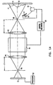
- Figures 1A and 1B illustrates two illustrative configurations of systems according to the present invention.
- a source of radiation 10 directs radiation at the scene 11 being observed.
- the scene depicted includes a three-dimensional object with reference being made herein to portions of the object which are relatively far and near, denoted 'A' and 'B', respectively.
- the radiation used may be any suitable radiation having a suitable wavelength for the distances examined and other suitable properties as will become more clear from the subsequent discussion.
- the radiation is visible or infrared radiation, such as laser radiation or stroboscopic light.
- the system further includes a detector 12 for detecting the intensity of radiation reflected from the objects in the scene.
- the detected radiation is that portion of the source radiation which impinges upon the object or objects of the scene and which is reflected back toward detector 12.
- the detector used may be any suitable detector with a suitable resolution and suitable number of gray levels including, but not limited to, a photographic film camera, electronic camera and a video camera, such as a CCD camera.
- the system includes a radiation source modulator, depicted schematically as item 16, for modulating radiation source 10 or the source radiation.
- the system further includes a detector modulator 18 for modulating the reflected radiation which is headed for detector 12.
- the word 'modulate' as used herein is intended to include any varying of the level of operation or any operating parameters of radiation source 10 or of the source radiation itself and/or of the reflected radiation, as appropriate, including, but not limited to, the alternate blocking and unblocking and the alternate activating and deactivating of radiation source 10 or the source radiation and detector 12 or the reflected radiation.
- Various mechanisms may be used to modulate radiation source 10 or the source radiation and the reflected radiation.
- the source radiation may be physically blocked periodically using a suitable shutter 17 or similar element.
- FIG. 1 Other mechanisms which may be used to modulate radiation source 10 include various high frequency electronic modulation means for periodically deactivating radiation source 10/and or detector 12. Depicted in Figure 1 is a source modulator 16 which is intended to convey the concept of electronically activating and deactivating radiation source 10.
- the reflected radiation is modulated with the help of various electro-optical modulators, such as, for example, KDP (KH 2 PO 4 ) or any other electro-optical crystal capable of modulating or switching light, lithium niobate and liquid crystals, having fast and accurate modulation capabilities or, preferably, gating, capabilities.
- electro-optical modulators such as, for example, KDP (KH 2 PO 4 ) or any other electro-optical crystal capable of modulating or switching light, lithium niobate and liquid crystals, having fast and accurate modulation capabilities or, preferably, gating, capabilities.
- a system according to the present invention includes a miniature iris 40 through which some of the radiation reflected from object 11 can pass. Radiation passing through iris 40 is then collimated using at least one collimating object lens 42. Iris 40 is located substantially at the focal point of collimating object lens 42.
- the collimated radiation then passes through a suitable acousto-optical device or an electro optical crystal, such as KDP 18 which serves as a modulation or gating device.
- a suitable acousto-optical device or an electro optical crystal such as KDP 18 which serves as a modulation or gating device.
- the modulated radiation exiting KDP 18 passes through at least one image lens 44 which sends the modulated radiation through an exit iris 46 placed substantially at the focal point of image lens 44. Radiation passing through exit iris 46 then impinges a suitable detector, such as a CCD sensor 12.
- a system according to the present invention includes mechanisms for controlling source modulator 16 and detector modulator 18.
- the mechanisms for controlling source modulator 16 and detector modulator 18 operate together in a coordinated manner, or, most preferably, are the same mechanism 20, so as to simultaneously control source modulator 16 and detector modulator 18.
- the simultaneous control may be synchronous so that the operation of both radiation source 10 and detector 12 is affected in the same way at the same time, i.e., synchronously.
- the simultaneous control is not limited to such synchronous control and a wide variety of other controls are possible.
- radiation source 10 and detector 12 may be open for different durations during each cycle and/or the unblocking of detector 12 may lag the unblocking of radiation source 10 during each cycle.
- a system according to the present invention further includes a suitable processor 22 which analyzes the intensity of radiation detected by detector 12 and determines the distances to various objects and portions of objects in the scene being examined.
- processor 22 analyzes the intensity of radiation detected by detector 12 and determines the distances to various objects and portions of objects in the scene being examined. The operation of processor 22 is explained in more detail below.
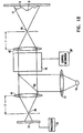
- FIG. 1B A variation of a system according to the present invention is depicted in Figure 1B.
- the configuration of Figure 1B differs from that of Figure 1A in a number of respects, the principal of these being that in Figure 1B the modulation of both the source and reflected radiation is effected by KDP 18.
- This feature of the configuration of Figure 1B dictates a number of changes in the configuration of the system.
- radiation source 10 is now input from the side into KDP 18.
- a beam splitter 50 is used to deflect a significant portion of the source radiation toward objects 11 and makes it possible for reflected radiation coming from objects 11 to pass through KDP 18 on its way to CCD sensor 12.
- the mechanism 20' which controls the modulation of KDP 18, is modified in that only a single device needs to be modulated instead of the synchronous control of two separate devices as in the configuration of Figure 1A.
- a typical system according to the present invention using a laser as the radiation source, a CCD sensor as the detector and modulating the source and detector by synchronous switching, would operate as follows.
- Radiation source (e.g., laser) 10 or the source radiation is modulated.
- KDP 18 modulates the reflected radiation passing through it in a manner which is synchronous with the modulation of the source radiation.
- KDP 18 modulates both the source radiation and the reflected radiation.
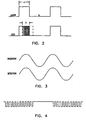
- FIG. 2 shows a type of square wave modulation
- the legend 'CCD' intending to indicate the modulation of the reflected radiation as it goes through KDP 18.
- both laser 10 and reflected radiation are active for a time ⁇ a' and are inactive for a time ⁇ D'.
- the times 'a' and 'b' may be the same or different.
- the wavelength of laser 10 and the time 'a' are selected so that light from laser 10 will be able to travel to the most distant objects of interest in the scene and be reflected back to CCD 12.
- the selection of the time 'a' can be illustrated with a simple example. Let us assume that the scene to be examined is as in Figure 1A and 1B with the maximum distance to be investigated being approximately 50 meters from the source or detector, i.e., both objects A and B are within about 50 meters from the detector and source. Light traveling from the source to the farthest object and back to the detector would take approximately 0.33 ⁇ sec to travel the 100 meters. Thus, the time duration 'a' should be approximately 0.33 ⁇ sec.
- Systems and methods according to the present invention are based on the idea that a near object will reflect light to the detector for a longer period of time during each cycle than a far object.
- the difference in duration of the detected reflected light during each cycle will translate to a different intensity, or gray level, on the detector.
- a certain point on object B is a certain number of meters away from the source and/or detector while a certain point on object A is a greater distance away
- reflected light from the point on B will start arriving at the detector relatively early in the active portion of the detector cycle (see Figure 2) and will continue to be received by the detector until the detector is deactivated at the end of the active portion of the detector cycle.
- the reflected light from the point on B will continue to proceed toward the detector for a period 'a' which corresponds to the period of irradiation (see the dot-dash-dot line in Figure 2). However, the portion of this reflected radiation which falls beyond the deactivation or blocking of the detector will not be received by the detector and will not contribute toward the intensity sensed by the corresponding pixels of the detector.
- the detector is such that the intensity of gray level of each pixel during each cycle is related to the amount of time in each cycle during which radiation was received by that pixel. Hence, the intensity, or gray level, can be translated to the distance, relative or absolute, of the point on the object.
- the synchronous on/off operation described in the example and depicted in Figure 2 is not the only possible mode of operation.
- Other modulations may be used.
- the radiation source and/or detector may be modulated harmonically as shown in Figure 3.
- the time duration 'b' during which the source/detector are inactive so that the bulk of the reflected radiation from faraway objects which are of no interest reaches the detector when the detector is deactivated and therefore do not contribute to the intensity detected by the corresponding pixel of the detector.
- a proper choice of the duration 'b' thus can be used to ensure that only reflected radiation from objects within the desired examination range are received during each specific cycle, thereby facilitating the interpretation of the intensity image.
- different portions of the various objects in the scene may have different reflectivities.
- the different reflectivities result from different colors, textures, and angles of the various portions of the objects.
- two points which are the same distance from the source/detector will be detected as having different intensities which could lead to false distance readings which are based on intensities, as described above.
- the intensity detected by a pixel of a detector receiving continuous radiation from a specific portion of a scene is directly proportional to the reflectivity of the portion of the scene being viewed and inversely proportional to the square of the distance between the portion of the scene being viewed and the detector.
- the detection during the pulsing portion of the cycle is used as described above.
- the continuous detection during the long active period of the cycle is used to correct, or normalize, the distances and compensate for differences in reflectivities.
- the compensation can be accomplished by any convenient method, for example, by dividing the intensity of each pixel during the continuous period by the intensity of the same pixel during the pulsed period, with the quotient between the two being directly proportional to the distance of the region being viewed by the pixel.
Description
- The present invention relates to three-dimensional cameras and, more particularly, to systems for accurately determining the distance to various objects and portions of objects in the scene.
- Various techniques are known for creating a three-dimensional image of a scene, i.e., a two-dimensional image which, in addition to indicating the lateral extent of objects in the scene, further indicates the relative or absolute distance of the objects, or portions thereof, from some reference point, such as the location of the camera.
- At least three basic techniques are commonly used to create such images. In one technique, a laser or similar source of radiation is used to send a pulse to a particular point in the scene. The reflected pulse is detected and the time of flight of the pulse, divided by two, is used to estimate the distance of the point. To obtain the distance of various points in the scene, the source is made to scan the scene, sending a series of pulses to successive points of the scene.
- In yet another technique, a phase shift, rather than time of flight, is measured and used to estimate distances. Here, too, the entire scene or relevant portions thereof must be scanned one point at a time.
- In a third technique, which also involves scanning, at least a single radiation source and corresponding detector are used, with suitable optics which act on the light in a manner which depends on the distance to the object being examined, to determine the distance to a particular point in the scene using a triangulation technique.
- The major disadvantage of all three of the above-described techniques is that each requires point by point or line by line scanning to determine the distance of the various objects in the scene. Such scanning significantly increases the frame time of the system, requires expensive scanning equipment and necessitates the use of fast and powerful computational means and complex programming.
- WO 89 12837 describes an optical radar system that acquires range data for a plurality of points in a scerie simultaneously. The system illuminates the scene with pulses of light and detects light reflected from the scene using a gated detector. Amounts of light reflected from pulses of light that reach the gated detector during its on times are used to determine distances to points in the scene.
- US 5,216,259 describes apparatus for determining distances to the scene that illuminates the scene with pulses of light. Light reflected from the pulses of light by the scene is modulated by a time dependent gain function. The modulated light from a pulse of light is processed to determine a measure of the gain that modulates the light and therefrom time delays between a time at which the pulse was transmitted and times at which light reflected from the pulse arrives at the apparatus. The time delays are used to determine ranges to regions of the scene.
- According to the present.invention there is provided a telecentric system for creating an image indicating distances to various objects in a scene, comprising: (a) a source of radiation for directing source radiation at the scene; (b) a detector for detecting the intensity of radiation reflected from the objects in the scene; (c) a source modulator for modulating the source of radiation; (d) means for collimating a portion of the radiation reflected from the objects in the scene; (e) a reflected radiation modulator for modulating the collimated radiation reflected from the objects in the scene, the reflected radiation modulator being selected from the group consisting of acousto-optical devices and electro-optical devices; (f) a source modulator control mechanism for controlling the source modulator; and (g) a reflected radiation modulator control mechanism for controlling the detector modulator.
- According to the invention a telecentric system is provided, having the features of claim 1.
- According to a preferred embodiment of the present invention, the source modulator control mechanism and the detector modulator control mechanism operate to simultaneously control the source modulator and the detector modulator.
- According to further features in preferred embodiments of the invention described below, the modulator of the source radiation and the modulator of the reflected radiation serve to alternately block and unblock or alternately activate and deactivate the source radiation and reflected radiation, respectively.
- According to still further features in the described preferred embodiments the source of radiation is a source of visible light, such as a laser and the detector includes photographic film, or a video camera sensor, such as a Charge Coupled Device (CCD.)
- According to yet further features, the method further includes processing the intensity of radiation reflected from the objects in the scene to determine distances of the objects and, in a most preferred embodiment, comparing the intensities detected during a relatively continuous irradiation and detector period with intensities detected during modulation of the source and the detector.
- Also according to the present invention there is provided a method for creating an image indicating distances to various objects in a scene, comprising: (a) directing source radiation at the scene using a radiation source; (b) detecting intensity of radiation reflected from the objects in the scene; (c) modulating the radiation source using a radiation source modulator; (d) collimating a portion of the radiation reflected from the objects in the scene; (e) modulating the collimated radiation reflected from the objects in the scene, the modulating of the reflected radiation being effected by a modulating device selected from the group consisting of acousto-optical devices and electro-optical devices; (f) controlling the source modulator; and (g) controlling the detector modulator.
- According to further features the method further includes processing the intensity of the radiation reflected from the objects in the scene to determine distances of the objects.
- In a preferred embodiment, the processing includes comparison of intensities detected during a relatively continuous irradiation and detector period with intensities detected during modulation of the source and the detector.
- The present invention successfully addresses the shortcomings of the presently known configurations by providing a system and method for quickly and readily determining distances to portions of a scene without the need for expensive and time consuming scanning of the scene.
- The invention is herein described, by way of example only, with reference to the accompanying drawings, wherein:
- FIG. 1A shows one possible configuration of a system and method according to the present invention;
- FIG. 1B depicts a second possible configuration of a system and method according to the present invention;
- FIG. 2 shows a typical modulation scheme which might be employed in a system and method of the present invention;
- FIG. 3 shows another modulation scheme which might be employed;
- FIG. 4 illustrates yet another modulation scheme which can be used to enhance the accuracy of a system and method according to the present invention.
- The present invention is of a system and method which can be used to determine the distance of various portions of a scene, especially a scene which is relatively near.
- The principles and operation of a system and method according to the present invention may be better understood with reference to the drawings and the accompanying description.
- Referring now to the drawings, Figures 1A and 1B illustrates two illustrative configurations of systems according to the present invention.
- With reference to the system of Figure 1A, a source of
radiation 10 directs radiation at thescene 11 being observed. For purposes of illustration, the scene depicted includes a three-dimensional object with reference being made herein to portions of the object which are relatively far and near, denoted 'A' and 'B', respectively. The radiation used may be any suitable radiation having a suitable wavelength for the distances examined and other suitable properties as will become more clear from the subsequent discussion. For most applications the radiation is visible or infrared radiation, such as laser radiation or stroboscopic light. - The system further includes a
detector 12 for detecting the intensity of radiation reflected from the objects in the scene. The detected radiation is that portion of the source radiation which impinges upon the object or objects of the scene and which is reflected back towarddetector 12. The detector used may be any suitable detector with a suitable resolution and suitable number of gray levels including, but not limited to, a photographic film camera, electronic camera and a video camera, such as a CCD camera. - The system includes a radiation source modulator, depicted schematically as
item 16, for modulatingradiation source 10 or the source radiation. The system further includes adetector modulator 18 for modulating the reflected radiation which is headed fordetector 12. - The word 'modulate' as used herein is intended to include any varying of the level of operation or any operating parameters of
radiation source 10 or of the source radiation itself and/or of the reflected radiation, as appropriate, including, but not limited to, the alternate blocking and unblocking and the alternate activating and deactivating ofradiation source 10 or the source radiation anddetector 12 or the reflected radiation. - Various mechanisms may be used to modulate
radiation source 10 or the source radiation and the reflected radiation. For example, the source radiation may be physically blocked periodically using a suitable shutter 17 or similar element. - Other mechanisms which may be used to modulate
radiation source 10 include various high frequency electronic modulation means for periodically deactivatingradiation source 10/and ordetector 12. Depicted in Figure 1 is asource modulator 16 which is intended to convey the concept of electronically activating and deactivatingradiation source 10. - Various means for modulating
detector 12 may be envisioned, including those analogous to the means for modulatingradiation source 10 described above. Preferably, the reflected radiation is modulated with the help of various electro-optical modulators, such as, for example, KDP (KH2PO4) or any other electro-optical crystal capable of modulating or switching light, lithium niobate and liquid crystals, having fast and accurate modulation capabilities or, preferably, gating, capabilities. - It is to be noted that whenever reference is made in the specification and claims to a radiation source modulator or to the modulation of the radiation source it is to be understood as involving the modulation of the radiation source itself and/or of the source radiation.
- A system according to the present invention includes a
miniature iris 40 through which some of the radiation reflected fromobject 11 can pass. Radiation passing throughiris 40 is then collimated using at least onecollimating object lens 42. Iris 40 is located substantially at the focal point of collimatingobject lens 42. - The collimated radiation then passes through a suitable acousto-optical device or an electro optical crystal, such as KDP 18 which serves as a modulation or gating device.
- The modulated
radiation exiting KDP 18 passes through at least one image lens 44 which sends the modulated radiation through anexit iris 46 placed substantially at the focal point of image lens 44. Radiation passing throughexit iris 46 then impinges a suitable detector, such as aCCD sensor 12. - Finally, a system according to the present invention includes mechanisms for controlling
source modulator 16 anddetector modulator 18. Preferably, the mechanisms for controllingsource modulator 16 anddetector modulator 18 operate together in a coordinated manner, or, most preferably, are thesame mechanism 20, so as to simultaneously controlsource modulator 16 anddetector modulator 18. - The simultaneous control may be synchronous so that the operation of both
radiation source 10 anddetector 12 is affected in the same way at the same time, i.e., synchronously. However, the simultaneous control is not limited to such synchronous control and a wide variety of other controls are possible. For example, and without in any way limiting the scope of the present invention, in the case of blocking and unblocking control,radiation source 10 anddetector 12 may be open for different durations during each cycle and/or the unblocking ofdetector 12 may lag the unblocking ofradiation source 10 during each cycle. - A system according to the present invention further includes a
suitable processor 22 which analyzes the intensity of radiation detected bydetector 12 and determines the distances to various objects and portions of objects in the scene being examined. The operation ofprocessor 22 is explained in more detail below. - A variation of a system according to the present invention is depicted in Figure 1B. The configuration of Figure 1B differs from that of Figure 1A in a number of respects, the principal of these being that in Figure 1B the modulation of both the source and reflected radiation is effected by
KDP 18. This feature of the configuration of Figure 1B dictates a number of changes in the configuration of the system. Thus,radiation source 10 is now input from the side intoKDP 18. Abeam splitter 50 is used to deflect a significant portion of the source radiation towardobjects 11 and makes it possible for reflected radiation coming fromobjects 11 to pass throughKDP 18 on its way toCCD sensor 12. The mechanism 20' which controls the modulation ofKDP 18, is modified in that only a single device needs to be modulated instead of the synchronous control of two separate devices as in the configuration of Figure 1A. - In operation, a typical system according to the present invention, using a laser as the radiation source, a CCD sensor as the detector and modulating the source and detector by synchronous switching, would operate as follows. Radiation source (e.g., laser) 10 or the source radiation is modulated.
KDP 18 modulates the reflected radiation passing through it in a manner which is synchronous with the modulation of the source radiation. In the configuration ofFigure 1B KDP 18 modulates both the source radiation and the reflected radiation. - This is schematically depicted in Figure 2 which shows a type of square wave modulation, the legend 'CCD' intending to indicate the modulation of the reflected radiation as it goes through
KDP 18. Thus during each cycle, bothlaser 10 and reflected radiation are active for a time `a' and are inactive for a time `D'. The times 'a' and 'b' may be the same or different. The wavelength oflaser 10 and the time 'a' are selected so that light fromlaser 10 will be able to travel to the most distant objects of interest in the scene and be reflected back toCCD 12. - The selection of the time 'a' can be illustrated with a simple example. Let us assume that the scene to be examined is as in Figure 1A and 1B with the maximum distance to be investigated being approximately 50 meters from the source or detector, i.e., both objects A and B are within about 50 meters from the detector and source. Light traveling from the source to the farthest object and back to the detector would take approximately 0.33 µsec to travel the 100 meters. Thus, the time duration 'a' should be approximately 0.33 µsec.
- Systems and methods according to the present invention are based on the idea that a near object will reflect light to the detector for a longer period of time during each cycle than a far object. The difference in duration of the detected reflected light during each cycle will translate to a different intensity, or gray level, on the detector. Thus, for example, if we assume that a certain point on object B is a certain number of meters away from the source and/or detector while a certain point on object A is a greater distance away, then reflected light from the point on B will start arriving at the detector relatively early in the active portion of the detector cycle (see Figure 2) and will continue to be received by the detector until the detector is deactivated at the end of the active portion of the detector cycle. The reflected light from the point on B will continue to proceed toward the detector for a period 'a' which corresponds to the period of irradiation (see the dot-dash-dot line in Figure 2). However, the portion of this reflected radiation which falls beyond the deactivation or blocking of the detector will not be received by the detector and will not contribute toward the intensity sensed by the corresponding pixels of the detector.
- By contrast, light reflected from the point on object A will start arriving at the detector later during the active portion of the detector cycle and will also continue to be received by the detector until the detector is deactivated.
- The result is that reflected light from a point on object B will have been received for a longer period of time than reflected light from a point on object A (see the shaded areas in Figure 2). The detector is such that the intensity of gray level of each pixel during each cycle is related to the amount of time in each cycle during which radiation was received by that pixel. Hence, the intensity, or gray level, can be translated to the distance, relative or absolute, of the point on the object.
- As stated above, the synchronous on/off operation described in the example and depicted in Figure 2, is not the only possible mode of operation. Other modulations may be used. For example, the radiation source and/or detector may be modulated harmonically as shown in Figure 3.
- To avoid obtaining false signals from distant objects which are beyond the region of interest, it may be desirable to increase the time duration 'b' during which the source/detector are inactive so that the bulk of the reflected radiation from faraway objects which are of no interest reaches the detector when the detector is deactivated and therefore do not contribute to the intensity detected by the corresponding pixel of the detector. A proper choice of the duration 'b' thus can be used to ensure that only reflected radiation from objects within the desired examination range are received during each specific cycle, thereby facilitating the interpretation of the intensity image.
- As will readily be appreciated, in certain applications, different portions of the various objects in the scene may have different reflectivities. The different reflectivities result from different colors, textures, and angles of the various portions of the objects. Thus, two points which are the same distance from the source/detector will be detected as having different intensities which could lead to false distance readings which are based on intensities, as described above.
- It is possible to readily compensate for differences in reflectivities of different objects or portions of objects being examined. As is well known, the intensity detected by a pixel of a detector receiving continuous radiation from a specific portion of a scene is directly proportional to the reflectivity of the portion of the scene being viewed and inversely proportional to the square of the distance between the portion of the scene being viewed and the detector.
- It can readily be shown that when a pulsed radiation source, such as those described above, is used the intensity detected by a pixel of a detector receiving radiation from a specific portion of a scene is still directly proportional to the reflectivity of the portion of the scene being viewed but is inversely proportional to the distance between the portion of the scene being viewed and the detector raised to the third power.
- Thus, to compensate for the effects of different reflectivities, one can use both continuous radiation and pulsed radiation. An example of such a cycle is shown in Figure 4. Here the radiation source and detector are active for a relatively long period of time to provide the continuous intensity of the objects in the scene. Periodically, the source and detector are deactivated and the source and detector are pulsed, in the same way as described above with reference to the basic embodiment, using one or more, preferably a train, of pulses.
- The detection during the pulsing portion of the cycle is used as described above. However, in addition, the continuous detection during the long active period of the cycle is used to correct, or normalize, the distances and compensate for differences in reflectivities. The compensation can be accomplished by any convenient method, for example, by dividing the intensity of each pixel during the continuous period by the intensity of the same pixel during the pulsed period, with the quotient between the two being directly proportional to the distance of the region being viewed by the pixel.
Claims (8)
- Apparatus for creating an image indicating distances to objects (A, B) in a scene (11), comprising- a modulated source of radiation (10), which directs radiation toward a scene, such that a portion of the radiation form the source is reflected form the scene and reaches the apparatus;- a detector (12), which detects an image formed from the radiation that reaches the apparatus;- a processor (22), which forms an image having an intensity value distribution indicative of the distance of objects from the apparatus, responsive to the intensity distribution of the detected image; and comprising- a first telecentric optics comprising at least one lens (42) and an iris (40) located substantially at the focal point of said at least one lens (42), which receives and collimates the radiation reflected from the scene that reaches the apparatus; and- a modulator (18), which modulates the collimated radiation, such that a part of the portion of the radiation which reaches the apparatus is passed by the modulator to a second telecentric optics comprising at east one image lens (44) that sends the light to pass through an iris (46) located substantially at the focal point of the image lens (44) wherein light that passes through the iris (46) forms the image detected by the detector, the part being dependent on the distance of respective portions of the scene form the apparatus.
- Apparatus according to claim 1 wherein the source (10) and detector (12) are boresighted.
- Apparatus according to claim 1 or claim 2 wherein the source of radiation comprises a continuos source of radiation which is modulated by the same modulator as the detected radiation.
- Apparatus according to any of the preceding claims wherein the modulated source of radiation directs radiation toward the scene along an axis such that a portion of the radiation from the source is reflected form the scene and reaches the apparatus.
- Apparatus according to any of the preceding claims and including a focusing lens (44) which receives the modulated collimated radiation and focuses it onto the detector (12).
- Apparatus according to any of the preceding claims wherein the modulator is an electro-optical modulator.
- Apparatus according to any of the preceding claims wherein the modulator is a KDP modulator.
- Apparatus according to any of the preceding claims wherein the modulator is an acousto-optical device.
Applications Claiming Priority (5)
| Application Number | Priority Date | Filing Date | Title |
|---|---|---|---|
| IL114278A IL114278A (en) | 1995-06-22 | 1995-06-22 | Camera and method |
| IL11427895 | 1995-06-22 | ||
| IL116223A IL116223A (en) | 1995-12-01 | 1995-12-01 | Telecentric 3d camera and method |
| IL11622395 | 1995-12-01 | ||
| PCT/IL1996/000021 WO1997001112A2 (en) | 1995-06-22 | 1996-06-20 | Telecentric 3d camera and method of rangefinding |
Publications (3)
| Publication Number | Publication Date |
|---|---|
| EP0886790A2 EP0886790A2 (en) | 1998-12-30 |
| EP0886790A4 EP0886790A4 (en) | 1999-01-07 |
| EP0886790B1 true EP0886790B1 (en) | 2006-03-01 |
Family
ID=26323086
Family Applications (2)
| Application Number | Title | Priority Date | Filing Date |
|---|---|---|---|
| EP96918825A Expired - Lifetime EP0835460B1 (en) | 1995-06-22 | 1996-06-20 | Improved optical ranging camera |
| EP96918826A Expired - Lifetime EP0886790B1 (en) | 1995-06-22 | 1996-06-20 | Telecentric 3d camera and method |
Family Applications Before (1)
| Application Number | Title | Priority Date | Filing Date |
|---|---|---|---|
| EP96918825A Expired - Lifetime EP0835460B1 (en) | 1995-06-22 | 1996-06-20 | Improved optical ranging camera |
Country Status (7)
| Country | Link |
|---|---|
| US (2) | US6091905A (en) |
| EP (2) | EP0835460B1 (en) |
| JP (8) | JP3869005B2 (en) |
| CN (3) | CN100524015C (en) |
| AU (2) | AU6135996A (en) |
| DE (2) | DE69635891T2 (en) |
| WO (2) | WO1997001111A2 (en) |
Families Citing this family (368)
| Publication number | Priority date | Publication date | Assignee | Title |
|---|---|---|---|---|
| US7655895B2 (en) * | 1992-05-05 | 2010-02-02 | Automotive Technologies International, Inc. | Vehicle-mounted monitoring arrangement and method using light-regulation |
| US9102220B2 (en) | 1992-05-05 | 2015-08-11 | American Vehicular Sciences Llc | Vehicular crash notification system |
| US9008854B2 (en) | 1995-06-07 | 2015-04-14 | American Vehicular Sciences Llc | Vehicle component control methods and systems |
| US10573093B2 (en) | 1995-06-07 | 2020-02-25 | Automotive Technologies International, Inc. | Vehicle computer design and use techniques for receiving navigation software |
| US9443358B2 (en) | 1995-06-07 | 2016-09-13 | Automotive Vehicular Sciences LLC | Vehicle software upgrade techniques |
| US6445884B1 (en) * | 1995-06-22 | 2002-09-03 | 3Dv Systems, Ltd. | Camera with through-the-lens lighting |
| AU6135996A (en) * | 1995-06-22 | 1997-01-22 | 3Dv Systems Ltd. | Improved optical ranging camera |
| US7744122B2 (en) | 1995-12-12 | 2010-06-29 | Automotive Technologies International, Inc. | Driver side aspirated airbags |
| JPH10222663A (en) * | 1997-01-31 | 1998-08-21 | Yamaha Motor Co Ltd | Picture recognition system and device therefor |
| EP0970502A1 (en) | 1997-03-07 | 2000-01-12 | 3DV Systems Ltd. | Optical shutter |
| JP2002508885A (en) | 1997-04-08 | 2002-03-19 | スリーディーヴィー システムズ リミテッド | Solid light shutter |
| EP1017973A1 (en) * | 1997-09-24 | 2000-07-12 | 3DV Systems Ltd. | Acoustical imaging system |
| US8209120B2 (en) | 1997-10-22 | 2012-06-26 | American Vehicular Sciences Llc | Vehicular map database management techniques |
| US8983771B2 (en) | 1997-10-22 | 2015-03-17 | Intelligent Technologies International, Inc. | Inter-vehicle information conveyance system and method |
| US9177476B2 (en) | 1997-10-22 | 2015-11-03 | American Vehicular Sciences Llc | Method and system for guiding a person to a location |
| US8060308B2 (en) | 1997-10-22 | 2011-11-15 | Intelligent Technologies International, Inc. | Weather monitoring techniques |
| US10358057B2 (en) | 1997-10-22 | 2019-07-23 | American Vehicular Sciences Llc | In-vehicle signage techniques |
| US8965677B2 (en) | 1998-10-22 | 2015-02-24 | Intelligent Technologies International, Inc. | Intra-vehicle information conveyance system and method |
| US9595139B1 (en) | 1997-10-22 | 2017-03-14 | Intelligent Technologies International, Inc. | Universal tolling system and method |
| US9691188B2 (en) | 1997-10-22 | 2017-06-27 | Intelligent Technologies International, Inc. | Tolling system and method using telecommunications |
| US9053633B2 (en) | 1997-10-22 | 2015-06-09 | Intelligent Technologies International, Inc. | Universal tolling system and method |
| US6765606B1 (en) | 1997-11-13 | 2004-07-20 | 3Dv Systems, Ltd. | Three dimension imaging by dual wavelength triangulation |
| EP1055146B1 (en) | 1998-02-08 | 2003-01-22 | 3DV Ltd. | Large aperture optical image shutter |
| JP3868621B2 (en) | 1998-03-17 | 2007-01-17 | 株式会社東芝 | Image acquisition apparatus, image acquisition method, and recording medium |
| US6587183B1 (en) * | 1998-05-25 | 2003-07-01 | Matsushita Electric Industrial Co., Ltd. | Range finder and camera |
| JP4105801B2 (en) * | 1998-07-02 | 2008-06-25 | ペンタックス株式会社 | 3D image input device |
| DE69827529T2 (en) | 1998-09-28 | 2005-11-10 | 3Dv Systems Ltd. | DISTANCE MEASUREMENT BY CAMERA |
| JP3840341B2 (en) * | 1998-10-15 | 2006-11-01 | 浜松ホトニクス株式会社 | Three-dimensional information detection method and apparatus |
| US10240935B2 (en) | 1998-10-22 | 2019-03-26 | American Vehicular Sciences Llc | Vehicle software upgrade techniques |
| US6876392B1 (en) * | 1998-12-22 | 2005-04-05 | Matsushita Electric Industrial Co., Ltd. | Rangefinder for obtaining information from a three-dimensional object |
| JP2000221037A (en) * | 1999-01-29 | 2000-08-11 | Topcon Corp | Automatic surveying machine and three-dimensional measuring method |
| JP4303354B2 (en) * | 1999-04-13 | 2009-07-29 | Hoya株式会社 | 3D image input device |
| JP4157223B2 (en) | 1999-04-13 | 2008-10-01 | Hoya株式会社 | 3D image input device |
| US6982761B1 (en) * | 1999-06-09 | 2006-01-03 | Pentax Corporation | Device for capturing three-dimensional images with independently controllable groups of photoelectric conversion elements |
| US6822687B1 (en) * | 1999-07-08 | 2004-11-23 | Pentax Corporation | Three-dimensional image capturing device and its laser emitting device |
| US6619406B1 (en) * | 1999-07-14 | 2003-09-16 | Cyra Technologies, Inc. | Advanced applications for 3-D autoscanning LIDAR system |
| JP4070909B2 (en) * | 1999-07-15 | 2008-04-02 | ペンタックス株式会社 | Electronic camera white balance control amount calculation device |
| US6961092B1 (en) | 1999-07-30 | 2005-11-01 | Pentax Corporation | Three-dimensional image capturing device |
| US6166811A (en) * | 1999-08-12 | 2000-12-26 | Perceptron, Inc. | Robot-based gauging system for determining three-dimensional measurement data |
| ATE285079T1 (en) | 1999-09-08 | 2005-01-15 | 3Dv Systems Ltd | 3D IMAGE PRODUCTION SYSTEM |
| US7196390B1 (en) | 1999-09-26 | 2007-03-27 | 3Dv Systems Ltd. | Solid state image wavelength converter |
| JP3875817B2 (en) | 1999-09-27 | 2007-01-31 | ペンタックス株式会社 | Map coordinate detection system for ranging device |
| JP3714063B2 (en) * | 1999-10-19 | 2005-11-09 | 富士ゼロックス株式会社 | 3D shape measuring device |
| JP2001153624A (en) | 1999-11-24 | 2001-06-08 | Asahi Optical Co Ltd | Three-dimensional image input device |
| US6856355B1 (en) * | 1999-11-30 | 2005-02-15 | Eastman Kodak Company | Method and apparatus for a color scannerless range image system |
| US6794628B2 (en) | 2000-01-03 | 2004-09-21 | 3Dv Systems, Ltd. | Solid state optical shutter |
| US6515737B2 (en) * | 2000-01-04 | 2003-02-04 | The Regents Of The University Of California | High-resolution imaging and target designation through clouds or smoke |
| US6349174B1 (en) * | 2000-05-17 | 2002-02-19 | Eastman Kodak Company | Method and apparatus for a color scannerless range imaging system |
| JP2001337166A (en) * | 2000-05-26 | 2001-12-07 | Minolta Co Ltd | Method and device for three-dimensional input |
| US6834128B1 (en) * | 2000-06-16 | 2004-12-21 | Hewlett-Packard Development Company, L.P. | Image mosaicing system and method adapted to mass-market hand-held digital cameras |
| JP2004503188A (en) | 2000-07-09 | 2004-01-29 | スリーディーヴィー システムズ リミテッド | Camera with through-the-lens illuminator |
| US6456793B1 (en) * | 2000-08-03 | 2002-09-24 | Eastman Kodak Company | Method and apparatus for a color scannerless range imaging system |
| US6411871B1 (en) * | 2000-08-05 | 2002-06-25 | American Gnc Corporation | Autonomous navigation, guidance and control using LDRI |
| US6535275B2 (en) * | 2000-08-09 | 2003-03-18 | Dialog Semiconductor Gmbh | High resolution 3-D imaging range finder |
| US6410930B1 (en) * | 2000-08-24 | 2002-06-25 | Eastman Kodak Company | Method and apparatus for aligning a color scannerless range imaging system |
| US6639684B1 (en) * | 2000-09-13 | 2003-10-28 | Nextengine, Inc. | Digitizer using intensity gradient to image features of three-dimensional objects |
| US7358986B1 (en) | 2000-09-13 | 2008-04-15 | Nextengine, Inc. | Digital imaging system having distribution controlled over a distributed network |
| WO2002023887A2 (en) * | 2000-09-13 | 2002-03-21 | Nextengine, Inc. | Imaging system monitored or controlled to ensure fidelity of file captured |
| US6856407B2 (en) * | 2000-09-13 | 2005-02-15 | Nextengine, Inc. | Method for depth detection in 3D imaging providing a depth measurement for each unitary group of pixels |
| US6958777B1 (en) * | 2000-09-29 | 2005-10-25 | Ess Technology, Inc. | Exposure control in electromechanical imaging devices |
| JP4533582B2 (en) * | 2000-12-11 | 2010-09-01 | カネスタ インコーポレイテッド | A CMOS compatible 3D image sensing system using quantum efficiency modulation |
| JP2002191554A (en) * | 2000-12-26 | 2002-07-09 | Asahi Optical Co Ltd | Electronic endoscope provided with three-dimensional image detector |
| US6999219B2 (en) | 2001-01-30 | 2006-02-14 | 3Dv Systems, Ltd. | Optical modulator |
| US7233351B1 (en) | 2001-02-23 | 2007-06-19 | Nextengine, Inc. | Method for high resolution incremental imaging |
| US6480265B2 (en) * | 2001-03-26 | 2002-11-12 | Deep Optic Ltd. | Active target distance measurement |
| JP4530571B2 (en) | 2001-04-16 | 2010-08-25 | Hoya株式会社 | 3D image detection device |
| JP3726699B2 (en) * | 2001-04-20 | 2005-12-14 | 日本ビクター株式会社 | Optical imaging device, optical distance measuring device |
| CA2348212A1 (en) * | 2001-05-24 | 2002-11-24 | Will Bauer | Automatic pan/tilt pointing device, luminaire follow-spot, and 6dof 3d position/orientation calculation information gathering system |
| JP4931288B2 (en) | 2001-06-08 | 2012-05-16 | ペンタックスリコーイメージング株式会社 | Image detection device and diaphragm device |
| US7160258B2 (en) | 2001-06-26 | 2007-01-09 | Entrack, Inc. | Capsule and method for treating or diagnosing the intestinal tract |
| DE10133126A1 (en) * | 2001-07-07 | 2003-01-16 | Philips Corp Intellectual Pty | Directionally sensitive audio pickup system for entertainment electronic appliance, has display and speaker to provide visual display and acoustical indication of pickup area of audio pickup system and interference sources |
| US7212278B2 (en) * | 2001-08-06 | 2007-05-01 | Siemens Aktiengesellschaft | Method and device for recording a three-dimensional distance-measuring image |
| JP2003149717A (en) * | 2001-11-19 | 2003-05-21 | Mitsubishi Heavy Ind Ltd | Method and device for image pickup |
| FR2832892B1 (en) * | 2001-11-27 | 2004-04-02 | Thomson Licensing Sa | SPECIAL EFFECTS VIDEO CAMERA |
| US20030147002A1 (en) * | 2002-02-06 | 2003-08-07 | Eastman Kodak Company | Method and apparatus for a color sequential scannerless range imaging system |
| EP1335235A3 (en) * | 2002-02-12 | 2003-09-17 | MARICO s.a.s di Dallara Riccardo & C. | A vision system using projection of figures of light |
| JP3832441B2 (en) | 2002-04-08 | 2006-10-11 | 松下電工株式会社 | Spatial information detection device using intensity-modulated light |
| AU2003225228A1 (en) | 2002-05-03 | 2003-11-17 | Donnelly Corporation | Object detection system for vehicle |
| US9007197B2 (en) * | 2002-05-20 | 2015-04-14 | Intelligent Technologies International, Inc. | Vehicular anticipatory sensor system |
| DE10223136C1 (en) * | 2002-05-24 | 2003-12-24 | Fraunhofer Ges Forschung | Procedure for adjusting and setting the depth measurement range of a studio camera |
| US20030235338A1 (en) * | 2002-06-19 | 2003-12-25 | Meetrix Corporation | Transmission of independently compressed video objects over internet protocol |
| US7429996B2 (en) * | 2002-07-16 | 2008-09-30 | Intel Corporation | Apparatus and method for sensing depth in every direction |
| US7161579B2 (en) * | 2002-07-18 | 2007-01-09 | Sony Computer Entertainment Inc. | Hand-held computer interactive device |
| US8947347B2 (en) * | 2003-08-27 | 2015-02-03 | Sony Computer Entertainment Inc. | Controlling actions in a video game unit |
| US7883415B2 (en) | 2003-09-15 | 2011-02-08 | Sony Computer Entertainment Inc. | Method and apparatus for adjusting a view of a scene being displayed according to tracked head motion |
| US7102615B2 (en) * | 2002-07-27 | 2006-09-05 | Sony Computer Entertainment Inc. | Man-machine interface using a deformable device |
| US7646372B2 (en) * | 2003-09-15 | 2010-01-12 | Sony Computer Entertainment Inc. | Methods and systems for enabling direction detection when interfacing with a computer program |
| US8797260B2 (en) | 2002-07-27 | 2014-08-05 | Sony Computer Entertainment Inc. | Inertially trackable hand-held controller |
| US7623115B2 (en) * | 2002-07-27 | 2009-11-24 | Sony Computer Entertainment Inc. | Method and apparatus for light input device |
| US7760248B2 (en) | 2002-07-27 | 2010-07-20 | Sony Computer Entertainment Inc. | Selective sound source listening in conjunction with computer interactive processing |
| US7854655B2 (en) | 2002-07-27 | 2010-12-21 | Sony Computer Entertainment America Inc. | Obtaining input for controlling execution of a game program |
| US8313380B2 (en) | 2002-07-27 | 2012-11-20 | Sony Computer Entertainment America Llc | Scheme for translating movements of a hand-held controller into inputs for a system |
| US8686939B2 (en) | 2002-07-27 | 2014-04-01 | Sony Computer Entertainment Inc. | System, method, and apparatus for three-dimensional input control |
| US7627139B2 (en) * | 2002-07-27 | 2009-12-01 | Sony Computer Entertainment Inc. | Computer image and audio processing of intensity and input devices for interfacing with a computer program |
| US7850526B2 (en) * | 2002-07-27 | 2010-12-14 | Sony Computer Entertainment America Inc. | System for tracking user manipulations within an environment |
| US7803050B2 (en) * | 2002-07-27 | 2010-09-28 | Sony Computer Entertainment Inc. | Tracking device with sound emitter for use in obtaining information for controlling game program execution |
| US9393487B2 (en) | 2002-07-27 | 2016-07-19 | Sony Interactive Entertainment Inc. | Method for mapping movements of a hand-held controller to game commands |
| US9474968B2 (en) | 2002-07-27 | 2016-10-25 | Sony Interactive Entertainment America Llc | Method and system for applying gearing effects to visual tracking |
| US8233642B2 (en) * | 2003-08-27 | 2012-07-31 | Sony Computer Entertainment Inc. | Methods and apparatuses for capturing an audio signal based on a location of the signal |
| US7918733B2 (en) * | 2002-07-27 | 2011-04-05 | Sony Computer Entertainment America Inc. | Multi-input game control mixer |
| US8139793B2 (en) * | 2003-08-27 | 2012-03-20 | Sony Computer Entertainment Inc. | Methods and apparatus for capturing audio signals based on a visual image |
| US8160269B2 (en) * | 2003-08-27 | 2012-04-17 | Sony Computer Entertainment Inc. | Methods and apparatuses for adjusting a listening area for capturing sounds |
| US9174119B2 (en) | 2002-07-27 | 2015-11-03 | Sony Computer Entertainement America, LLC | Controller for providing inputs to control execution of a program when inputs are combined |
| US8570378B2 (en) | 2002-07-27 | 2013-10-29 | Sony Computer Entertainment Inc. | Method and apparatus for tracking three-dimensional movements of an object using a depth sensing camera |
| US9682319B2 (en) | 2002-07-31 | 2017-06-20 | Sony Interactive Entertainment Inc. | Combiner method for altering game gearing |
| US9177387B2 (en) | 2003-02-11 | 2015-11-03 | Sony Computer Entertainment Inc. | Method and apparatus for real time motion capture |
| US7186969B2 (en) * | 2003-02-12 | 2007-03-06 | Mitutoyo Corporation | Optical configuration for imaging-type optical encoders |
| US7505862B2 (en) * | 2003-03-07 | 2009-03-17 | Salmon Technologies, Llc | Apparatus and method for testing electronic systems |
| EP1418401A1 (en) * | 2003-03-26 | 2004-05-12 | Leica Geosystems AG | Method and device for airborne or spaceborne photogrammetry |
| JP2004312249A (en) * | 2003-04-04 | 2004-11-04 | Olympus Corp | Camera |
| US6791673B1 (en) * | 2003-04-07 | 2004-09-14 | Robert E. Malm | Ground surveillance system |
| NZ525241A (en) * | 2003-04-08 | 2006-02-24 | Univ Waikato | Range sensing system with shuttered receiver. |
| US7316930B1 (en) | 2003-04-21 | 2008-01-08 | National Semiconductor Corporation | Use of vertically stacked photodiodes in a gene chip system |
| JP4355341B2 (en) * | 2003-05-29 | 2009-10-28 | 本田技研工業株式会社 | Visual tracking using depth data |
| US8072470B2 (en) | 2003-05-29 | 2011-12-06 | Sony Computer Entertainment Inc. | System and method for providing a real-time three-dimensional interactive environment |
| US7620202B2 (en) * | 2003-06-12 | 2009-11-17 | Honda Motor Co., Ltd. | Target orientation estimation using depth sensing |
| US7044908B1 (en) | 2003-07-08 | 2006-05-16 | National Semiconductor Corporation | Method and system for dynamically adjusting field of view in a capsule endoscope |
| ITRM20030360A1 (en) * | 2003-07-23 | 2005-01-24 | Marcello Marzoli | PROCEDURE OF THREE-DIMENSIONAL RECONSTRUCTION OF IMAGES |
| US7399274B1 (en) | 2003-08-19 | 2008-07-15 | National Semiconductor Corporation | Sensor configuration for a capsule endoscope |
| US7191164B2 (en) * | 2003-08-19 | 2007-03-13 | Intel Corporation | Searching for object images with reduced computation |
| US20070223732A1 (en) * | 2003-08-27 | 2007-09-27 | Mao Xiao D | Methods and apparatuses for adjusting a visual image based on an audio signal |
| US8323106B2 (en) | 2008-05-30 | 2012-12-04 | Sony Computer Entertainment America Llc | Determination of controller three-dimensional location using image analysis and ultrasonic communication |
| US7874917B2 (en) | 2003-09-15 | 2011-01-25 | Sony Computer Entertainment Inc. | Methods and systems for enabling depth and direction detection when interfacing with a computer program |
| US9573056B2 (en) | 2005-10-26 | 2017-02-21 | Sony Interactive Entertainment Inc. | Expandable control device via hardware attachment |
| US8287373B2 (en) | 2008-12-05 | 2012-10-16 | Sony Computer Entertainment Inc. | Control device for communicating visual information |
| US10279254B2 (en) * | 2005-10-26 | 2019-05-07 | Sony Interactive Entertainment Inc. | Controller having visually trackable object for interfacing with a gaming system |
| WO2005036372A2 (en) * | 2003-10-09 | 2005-04-21 | Honda Motor Co., Ltd. | Systems and methods for determining depth using shuttered light pulses |
| US7110100B2 (en) * | 2003-11-04 | 2006-09-19 | Electronic Scripting Products, Inc. | Apparatus and method for determining an inclination of an elongate object contacting a plane surface |
| US20050134608A1 (en) * | 2003-12-19 | 2005-06-23 | Texas Instruments Incorporated | Method, and related system, for overlaying a graphics object on a digital picture |
| US7663689B2 (en) | 2004-01-16 | 2010-02-16 | Sony Computer Entertainment Inc. | Method and apparatus for optimizing capture device settings through depth information |
| DE102004009541A1 (en) * | 2004-02-23 | 2005-09-15 | Iris-Gmbh Infrared & Intelligent Sensors | User controllable acquisition system |
| US7023536B2 (en) * | 2004-03-08 | 2006-04-04 | Electronic Scripting Products, Inc. | Apparatus and method for determining orientation parameters of an elongate object |
| DE102004014048B4 (en) * | 2004-03-19 | 2008-10-30 | Sirona Dental Systems Gmbh | Measuring device and method according to the basic principle of confocal microscopy |
| US7161664B2 (en) | 2004-04-13 | 2007-01-09 | Electronic Scripting Products, Inc. | Apparatus and method for optical determination of intermediate distances |
| US7526103B2 (en) | 2004-04-15 | 2009-04-28 | Donnelly Corporation | Imaging system for vehicle |
| US7711179B2 (en) * | 2004-04-21 | 2010-05-04 | Nextengine, Inc. | Hand held portable three dimensional scanner |
| DE602005004332T2 (en) | 2004-06-17 | 2009-01-08 | Cadent Ltd. | Method for providing data related to the oral cavity |
| JP4645177B2 (en) * | 2004-11-30 | 2011-03-09 | パナソニック電工株式会社 | Measuring device |
| EP2312336B1 (en) * | 2004-07-30 | 2012-03-14 | Panasonic Corporation | Image processing device |
| US7843488B2 (en) * | 2004-08-09 | 2010-11-30 | Stapleton John J | Vision thermalization for sightless and visually impaired |
| US8547401B2 (en) | 2004-08-19 | 2013-10-01 | Sony Computer Entertainment Inc. | Portable augmented reality device and method |
| JP4525253B2 (en) * | 2004-08-30 | 2010-08-18 | オムロン株式会社 | Optical sensor and distance measuring method |
| US20060045174A1 (en) * | 2004-08-31 | 2006-03-02 | Ittiam Systems (P) Ltd. | Method and apparatus for synchronizing a transmitter clock of an analog modem to a remote clock |
| JP2008529709A (en) * | 2005-02-17 | 2008-08-07 | スリー ディーブイ システムズ エルティーディー | Method and apparatus for imaging tissue |
| US9247215B1 (en) * | 2005-04-22 | 2016-01-26 | Custom Manufacturing & Engineering, Inc. | Laser sensor system |
| RU2298223C2 (en) * | 2005-04-25 | 2007-04-27 | Самсунг Электроникс Ко., Лтд. | System and method for correcting dark tones on digital photographs |
| US8294809B2 (en) | 2005-05-10 | 2012-10-23 | Advanced Scientific Concepts, Inc. | Dimensioning system |
| US7991242B2 (en) | 2005-05-11 | 2011-08-02 | Optosecurity Inc. | Apparatus, method and system for screening receptacles and persons, having image distortion correction functionality |
| EP1886257A1 (en) | 2005-05-11 | 2008-02-13 | Optosecurity Inc. | Method and system for screening luggage items, cargo containers or persons |
| JP2006337286A (en) * | 2005-06-03 | 2006-12-14 | Ricoh Co Ltd | Shape-measuring device |
| JP2007214527A (en) * | 2006-01-13 | 2007-08-23 | Ihi Corp | Laser annealing method and laser annealer |
| US7995834B1 (en) | 2006-01-20 | 2011-08-09 | Nextengine, Inc. | Multiple laser scanner |
| US20110014981A1 (en) * | 2006-05-08 | 2011-01-20 | Sony Computer Entertainment Inc. | Tracking device with sound emitter for use in obtaining information for controlling game program execution |
| US7899232B2 (en) | 2006-05-11 | 2011-03-01 | Optosecurity Inc. | Method and apparatus for providing threat image projection (TIP) in a luggage screening system, and luggage screening system implementing same |
| JP4395150B2 (en) * | 2006-06-28 | 2010-01-06 | 富士フイルム株式会社 | Distance image sensor |
| US7835221B2 (en) * | 2006-07-06 | 2010-11-16 | Westerngeco L.L.C. | Optical methods and systems in marine seismic surveying |
| US8494210B2 (en) | 2007-03-30 | 2013-07-23 | Optosecurity Inc. | User interface for use in security screening providing image enhancement capabilities and apparatus for implementing same |
| US7972045B2 (en) | 2006-08-11 | 2011-07-05 | Donnelly Corporation | Automatic headlamp control system |
| JP4440239B2 (en) * | 2006-08-18 | 2010-03-24 | 富士フイルム株式会社 | Distance image creation method, distance image sensor, and photographing apparatus |
| CN100592127C (en) * | 2006-09-06 | 2010-02-24 | 鸿富锦精密工业(深圳)有限公司 | Camera module group |
| US8781151B2 (en) | 2006-09-28 | 2014-07-15 | Sony Computer Entertainment Inc. | Object detection using video input combined with tilt angle information |
| USRE48417E1 (en) | 2006-09-28 | 2021-02-02 | Sony Interactive Entertainment Inc. | Object direction using video input combined with tilt angle information |
| US8310656B2 (en) | 2006-09-28 | 2012-11-13 | Sony Computer Entertainment America Llc | Mapping movements of a hand-held controller to the two-dimensional image plane of a display screen |
| US7891818B2 (en) | 2006-12-12 | 2011-02-22 | Evans & Sutherland Computer Corporation | System and method for aligning RGB light in a single modulator projector |
| JP2010516153A (en) * | 2007-01-14 | 2010-05-13 | マイクロソフト インターナショナル ホールディングス ビイ.ヴイ. | Method, apparatus and system for image processing |
| US20080231835A1 (en) * | 2007-03-23 | 2008-09-25 | Keigo Iizuka | Divergence ratio distance mapping camera |
| US8542907B2 (en) * | 2007-12-17 | 2013-09-24 | Sony Computer Entertainment America Llc | Dynamic three-dimensional object mapping for user-defined control device |
| CN102099703A (en) * | 2007-12-19 | 2011-06-15 | 微软国际控股私有有限公司 | 3d camera and methods of gating thereof |
| US8149210B2 (en) * | 2007-12-31 | 2012-04-03 | Microsoft International Holdings B.V. | Pointing device and method |
| US8840470B2 (en) | 2008-02-27 | 2014-09-23 | Sony Computer Entertainment America Llc | Methods for capturing depth data of a scene and applying computer actions |
| US8121351B2 (en) * | 2008-03-09 | 2012-02-21 | Microsoft International Holdings B.V. | Identification of objects in a 3D video using non/over reflective clothing |
| US8368753B2 (en) | 2008-03-17 | 2013-02-05 | Sony Computer Entertainment America Llc | Controller with an integrated depth camera |
| JP2009276248A (en) * | 2008-05-15 | 2009-11-26 | Mitsubishi Electric Corp | Laser radar device |
| US8358317B2 (en) | 2008-05-23 | 2013-01-22 | Evans & Sutherland Computer Corporation | System and method for displaying a planar image on a curved surface |
| US8187097B1 (en) | 2008-06-04 | 2012-05-29 | Zhang Evan Y W | Measurement and segment of participant's motion in game play |
| US8702248B1 (en) | 2008-06-11 | 2014-04-22 | Evans & Sutherland Computer Corporation | Projection method for reducing interpixel gaps on a viewing surface |
| US8227965B2 (en) | 2008-06-20 | 2012-07-24 | Arradiance, Inc. | Microchannel plate devices with tunable resistive films |
| US8890952B2 (en) | 2008-07-29 | 2014-11-18 | Microsoft Corporation | Imaging system |
| US8682522B2 (en) * | 2008-08-18 | 2014-03-25 | Raytheon Company | Systems and methods for triaging a plurality of targets with a robotic vehicle |
| US8133119B2 (en) * | 2008-10-01 | 2012-03-13 | Microsoft Corporation | Adaptation for alternate gaming input devices |
| DE102008052064B4 (en) * | 2008-10-17 | 2010-09-09 | Diehl Bgt Defence Gmbh & Co. Kg | Device for taking pictures of an object scene |
| US8077378B1 (en) | 2008-11-12 | 2011-12-13 | Evans & Sutherland Computer Corporation | Calibration system and method for light modulation device |
| HUE039300T2 (en) | 2008-11-25 | 2018-12-28 | Tetravue Inc | Systems and methods of high resolution three-dimensional imaging |
| US8961313B2 (en) | 2009-05-29 | 2015-02-24 | Sony Computer Entertainment America Llc | Multi-positional three-dimensional controller |
| EP2200006B1 (en) * | 2008-12-19 | 2013-03-13 | Saab Ab | Method and arrangement for estimating at least one parameter of an intruder |
| US8681321B2 (en) * | 2009-01-04 | 2014-03-25 | Microsoft International Holdings B.V. | Gated 3D camera |
| JP5230456B2 (en) * | 2009-01-09 | 2013-07-10 | キヤノン株式会社 | Image processing apparatus and image processing method |
| US8295546B2 (en) | 2009-01-30 | 2012-10-23 | Microsoft Corporation | Pose tracking pipeline |
| US8294767B2 (en) | 2009-01-30 | 2012-10-23 | Microsoft Corporation | Body scan |
| US9652030B2 (en) | 2009-01-30 | 2017-05-16 | Microsoft Technology Licensing, Llc | Navigation of a virtual plane using a zone of restriction for canceling noise |
| US8866821B2 (en) | 2009-01-30 | 2014-10-21 | Microsoft Corporation | Depth map movement tracking via optical flow and velocity prediction |
| US8773355B2 (en) * | 2009-03-16 | 2014-07-08 | Microsoft Corporation | Adaptive cursor sizing |
| US8988437B2 (en) * | 2009-03-20 | 2015-03-24 | Microsoft Technology Licensing, Llc | Chaining animations |
| US8527657B2 (en) * | 2009-03-20 | 2013-09-03 | Sony Computer Entertainment America Llc | Methods and systems for dynamically adjusting update rates in multi-player network gaming |
| US9256282B2 (en) * | 2009-03-20 | 2016-02-09 | Microsoft Technology Licensing, Llc | Virtual object manipulation |
| EP2236980B1 (en) * | 2009-03-31 | 2018-05-02 | Alcatel Lucent | A method for determining the relative position of a first and a second imaging device and devices therefore |
| US8342963B2 (en) | 2009-04-10 | 2013-01-01 | Sony Computer Entertainment America Inc. | Methods and systems for enabling control of artificial intelligence game characters |
| US9498718B2 (en) * | 2009-05-01 | 2016-11-22 | Microsoft Technology Licensing, Llc | Altering a view perspective within a display environment |
| US9898675B2 (en) * | 2009-05-01 | 2018-02-20 | Microsoft Technology Licensing, Llc | User movement tracking feedback to improve tracking |
| US8942428B2 (en) | 2009-05-01 | 2015-01-27 | Microsoft Corporation | Isolate extraneous motions |
| US8253746B2 (en) * | 2009-05-01 | 2012-08-28 | Microsoft Corporation | Determine intended motions |
| US8181123B2 (en) * | 2009-05-01 | 2012-05-15 | Microsoft Corporation | Managing virtual port associations to users in a gesture-based computing environment |
| US9015638B2 (en) * | 2009-05-01 | 2015-04-21 | Microsoft Technology Licensing, Llc | Binding users to a gesture based system and providing feedback to the users |
| US8503720B2 (en) * | 2009-05-01 | 2013-08-06 | Microsoft Corporation | Human body pose estimation |
| US9377857B2 (en) * | 2009-05-01 | 2016-06-28 | Microsoft Technology Licensing, Llc | Show body position |
| US8340432B2 (en) | 2009-05-01 | 2012-12-25 | Microsoft Corporation | Systems and methods for detecting a tilt angle from a depth image |
| US8649554B2 (en) | 2009-05-01 | 2014-02-11 | Microsoft Corporation | Method to control perspective for a camera-controlled computer |
| US20100277470A1 (en) * | 2009-05-01 | 2010-11-04 | Microsoft Corporation | Systems And Methods For Applying Model Tracking To Motion Capture |
| US8638985B2 (en) | 2009-05-01 | 2014-01-28 | Microsoft Corporation | Human body pose estimation |
| US8142288B2 (en) | 2009-05-08 | 2012-03-27 | Sony Computer Entertainment America Llc | Base station movement detection and compensation |
| US8393964B2 (en) | 2009-05-08 | 2013-03-12 | Sony Computer Entertainment America Llc | Base station for position location |
| US20100302376A1 (en) * | 2009-05-27 | 2010-12-02 | Pierre Benoit Boulanger | System and method for high-quality real-time foreground/background separation in tele-conferencing using self-registered color/infrared input images and closed-form natural image matting techniques |
| ES2553111T3 (en) | 2009-05-28 | 2015-12-04 | Ben Gurion University Of The Negev Research And Development Authority | Balance disturbance system and trainer |
| US20100302365A1 (en) * | 2009-05-29 | 2010-12-02 | Microsoft Corporation | Depth Image Noise Reduction |
| US8145594B2 (en) * | 2009-05-29 | 2012-03-27 | Microsoft Corporation | Localized gesture aggregation |
| US20100306716A1 (en) * | 2009-05-29 | 2010-12-02 | Microsoft Corporation | Extending standard gestures |
| US8320619B2 (en) | 2009-05-29 | 2012-11-27 | Microsoft Corporation | Systems and methods for tracking a model |
| US9400559B2 (en) | 2009-05-29 | 2016-07-26 | Microsoft Technology Licensing, Llc | Gesture shortcuts |
| US8744121B2 (en) | 2009-05-29 | 2014-06-03 | Microsoft Corporation | Device for identifying and tracking multiple humans over time |
| US20100306685A1 (en) * | 2009-05-29 | 2010-12-02 | Microsoft Corporation | User movement feedback via on-screen avatars |
| US8509479B2 (en) | 2009-05-29 | 2013-08-13 | Microsoft Corporation | Virtual object |
| US20100302138A1 (en) * | 2009-05-29 | 2010-12-02 | Microsoft Corporation | Methods and systems for defining or modifying a visual representation |
| US8803889B2 (en) | 2009-05-29 | 2014-08-12 | Microsoft Corporation | Systems and methods for applying animations or motions to a character |
| US8542252B2 (en) * | 2009-05-29 | 2013-09-24 | Microsoft Corporation | Target digitization, extraction, and tracking |
| US9182814B2 (en) * | 2009-05-29 | 2015-11-10 | Microsoft Technology Licensing, Llc | Systems and methods for estimating a non-visible or occluded body part |
| US8379101B2 (en) | 2009-05-29 | 2013-02-19 | Microsoft Corporation | Environment and/or target segmentation |
| US8418085B2 (en) * | 2009-05-29 | 2013-04-09 | Microsoft Corporation | Gesture coach |
| US8176442B2 (en) * | 2009-05-29 | 2012-05-08 | Microsoft Corporation | Living cursor control mechanics |
| US8625837B2 (en) * | 2009-05-29 | 2014-01-07 | Microsoft Corporation | Protocol and format for communicating an image from a camera to a computing environment |
| US9383823B2 (en) | 2009-05-29 | 2016-07-05 | Microsoft Technology Licensing, Llc | Combining gestures beyond skeletal |
| US8856691B2 (en) * | 2009-05-29 | 2014-10-07 | Microsoft Corporation | Gesture tool |
| US7914344B2 (en) * | 2009-06-03 | 2011-03-29 | Microsoft Corporation | Dual-barrel, connector jack and plug assemblies |
| US8390680B2 (en) | 2009-07-09 | 2013-03-05 | Microsoft Corporation | Visual representation expression based on player expression |
| US9159151B2 (en) * | 2009-07-13 | 2015-10-13 | Microsoft Technology Licensing, Llc | Bringing a visual representation to life via learned input from the user |
| US20110025689A1 (en) * | 2009-07-29 | 2011-02-03 | Microsoft Corporation | Auto-Generating A Visual Representation |
| US9141193B2 (en) * | 2009-08-31 | 2015-09-22 | Microsoft Technology Licensing, Llc | Techniques for using human gestures to control gesture unaware programs |
| US9014546B2 (en) | 2009-09-23 | 2015-04-21 | Rovi Guides, Inc. | Systems and methods for automatically detecting users within detection regions of media devices |
| US20110109617A1 (en) * | 2009-11-12 | 2011-05-12 | Microsoft Corporation | Visualizing Depth |
| KR101675112B1 (en) * | 2010-01-21 | 2016-11-22 | 삼성전자주식회사 | Method of extractig depth information and optical apparatus employing the method |
| US8134719B2 (en) * | 2010-03-19 | 2012-03-13 | Carestream Health, Inc. | 3-D imaging using telecentric defocus |
| JP5519381B2 (en) * | 2010-04-09 | 2014-06-11 | トヨタ自動車株式会社 | Spectrum measuring device |
| DE102010028949A1 (en) * | 2010-05-12 | 2011-11-17 | Osram Gesellschaft mit beschränkter Haftung | headlight module |
| US8384770B2 (en) * | 2010-06-02 | 2013-02-26 | Nintendo Co., Ltd. | Image display system, image display apparatus, and image display method |
| US10628729B2 (en) | 2010-06-08 | 2020-04-21 | Styku, LLC | System and method for body scanning and avatar creation |
| US10628666B2 (en) | 2010-06-08 | 2020-04-21 | Styku, LLC | Cloud server body scan data system |
| US11640672B2 (en) | 2010-06-08 | 2023-05-02 | Styku Llc | Method and system for wireless ultra-low footprint body scanning |
| US11244223B2 (en) | 2010-06-08 | 2022-02-08 | Iva Sareen | Online garment design and collaboration system and method |
| EP2395767B1 (en) | 2010-06-11 | 2014-11-12 | Nintendo Co., Ltd. | Image display program, image display system, and image display method |
| TWI540312B (en) * | 2010-06-15 | 2016-07-01 | 原相科技股份有限公司 | Time of flight system capable of increasing measurement accuracy, saving power and/or increasing motion detection rate and method thereof |
| CN102346020B (en) * | 2010-08-04 | 2013-10-23 | 原相科技股份有限公司 | Three-dimensional information generation device and method for interactive interface |
| KR101753312B1 (en) * | 2010-09-17 | 2017-07-03 | 삼성전자주식회사 | Apparatus and method for generating depth image |
| JP5739674B2 (en) | 2010-09-27 | 2015-06-24 | 任天堂株式会社 | Information processing program, information processing apparatus, information processing system, and information processing method |
| US8681255B2 (en) | 2010-09-28 | 2014-03-25 | Microsoft Corporation | Integrated low power depth camera and projection device |
| US9344736B2 (en) | 2010-09-30 | 2016-05-17 | Alcatel Lucent | Systems and methods for compressive sense imaging |
| US9319578B2 (en) * | 2012-10-24 | 2016-04-19 | Alcatel Lucent | Resolution and focus enhancement |
| US9484065B2 (en) | 2010-10-15 | 2016-11-01 | Microsoft Technology Licensing, Llc | Intelligent determination of replays based on event identification |
| US8667519B2 (en) | 2010-11-12 | 2014-03-04 | Microsoft Corporation | Automatic passive and anonymous feedback system |
| JP5574927B2 (en) * | 2010-11-19 | 2014-08-20 | キヤノン株式会社 | measuring device |
| KR101691156B1 (en) * | 2010-12-14 | 2016-12-30 | 삼성전자주식회사 | Optical system having integrated illumination and imaging systems and 3D image acquisition apparatus including the optical system |
| KR101798063B1 (en) | 2010-12-14 | 2017-11-15 | 삼성전자주식회사 | Illumination optical system and 3D image acquisition apparatus including the same |
| US20120154535A1 (en) * | 2010-12-15 | 2012-06-21 | Microsoft Corporation | Capturing gated and ungated light in the same frame on the same photosurface |
| GB2486467A (en) | 2010-12-16 | 2012-06-20 | Thermo Electron Mfg Ltd | Hybrid electrical/optical cable uses transparent insulating material as optical waveguide |
| KR101722641B1 (en) | 2010-12-23 | 2017-04-04 | 삼성전자주식회사 | 3D image acquisition apparatus and method of extractig depth information in the 3D image acquisition apparatus |
| DE102011010334B4 (en) * | 2011-02-04 | 2014-08-28 | Eads Deutschland Gmbh | Camera system and method for observing objects at a great distance, in particular for monitoring target objects at night, mist, dust or rain |
| US8942917B2 (en) | 2011-02-14 | 2015-01-27 | Microsoft Corporation | Change invariant scene recognition by an agent |
| WO2012110924A1 (en) * | 2011-02-15 | 2012-08-23 | Basf Se | Detector for optically detecting at least one object |
| US8620113B2 (en) | 2011-04-25 | 2013-12-31 | Microsoft Corporation | Laser diode modes |
| US8921748B2 (en) * | 2011-05-19 | 2014-12-30 | Lockheed Martin Corporation | Optical window and detection system employing the same |
| US8760395B2 (en) | 2011-05-31 | 2014-06-24 | Microsoft Corporation | Gesture recognition techniques |
| US10007330B2 (en) | 2011-06-21 | 2018-06-26 | Microsoft Technology Licensing, Llc | Region of interest segmentation |
| US8672838B2 (en) * | 2011-08-12 | 2014-03-18 | Intuitive Surgical Operations, Inc. | Image capture unit in a surgical instrument |
| US8734328B2 (en) | 2011-08-12 | 2014-05-27 | Intuitive Surgical Operations, Inc. | Increased resolution and dynamic range image capture unit in a surgical instrument and method |
| CN103917862A (en) | 2011-09-07 | 2014-07-09 | 拉皮斯坎系统股份有限公司 | X-ray inspection system that integrates manifest data with imaging/detection processing |
| CN103037173B (en) * | 2011-09-28 | 2015-07-08 | 原相科技股份有限公司 | Image system |
| TWI526706B (en) | 2011-10-05 | 2016-03-21 | 原相科技股份有限公司 | Image system |
| US9641826B1 (en) | 2011-10-06 | 2017-05-02 | Evans & Sutherland Computer Corporation | System and method for displaying distant 3-D stereo on a dome surface |
| KR101854188B1 (en) * | 2011-10-25 | 2018-05-08 | 삼성전자주식회사 | 3D image acquisition apparatus and method of acqiring depth information in the 3D image acquisition apparatus |
| JP5896702B2 (en) * | 2011-11-30 | 2016-03-30 | オリンパス株式会社 | Photoacoustic microscope |
| US8635637B2 (en) | 2011-12-02 | 2014-01-21 | Microsoft Corporation | User interface presenting an animated avatar performing a media reaction |
| US9100685B2 (en) | 2011-12-09 | 2015-08-04 | Microsoft Technology Licensing, Llc | Determining audience state or interest using passive sensor data |
| JP5576851B2 (en) * | 2011-12-27 | 2014-08-20 | 本田技研工業株式会社 | Ranging system and ranging method |
| IL217361A0 (en) * | 2012-01-04 | 2012-03-29 | Rafael Advanced Defense Sys | Device & method providing combined video camera and range finder functionality |
| KR101955334B1 (en) | 2012-02-07 | 2019-03-07 | 삼성전자주식회사 | 3D image acquisition apparatus and method of extractig depth information in the 3D image acquisition apparatus |
| US8898687B2 (en) | 2012-04-04 | 2014-11-25 | Microsoft Corporation | Controlling a media program based on a media reaction |
| US9723233B2 (en) | 2012-04-18 | 2017-08-01 | Brightway Vision Ltd. | Controllable gated sensor |
| US9046363B2 (en) * | 2012-04-27 | 2015-06-02 | SATOP GmbH | Using multispectral satellite data to determine littoral water depths despite varying water turbidity |
| CA2775700C (en) | 2012-05-04 | 2013-07-23 | Microsoft Corporation | Determining a future portion of a currently presented media program |
| JP6011040B2 (en) * | 2012-06-07 | 2016-10-19 | オムロン株式会社 | Photoelectric sensor |
| TWM446323U (en) * | 2012-08-03 | 2013-02-01 | Ind Tech Res Inst | Aperture ratio measurement device, opening distance sensing device and light sensing module |
| US9071763B1 (en) * | 2012-09-26 | 2015-06-30 | Google Inc. | Uniform illumination image capture |
| KR20140064478A (en) | 2012-11-20 | 2014-05-28 | 삼성디스플레이 주식회사 | Image sensing unit, 3d image management apparatus, 3d camera system, and 3d image management method |
| US9857470B2 (en) | 2012-12-28 | 2018-01-02 | Microsoft Technology Licensing, Llc | Using photometric stereo for 3D environment modeling |
| WO2014119241A1 (en) * | 2013-01-31 | 2014-08-07 | パナソニック株式会社 | Distance measurement method and distance measurement system |
| US9940553B2 (en) | 2013-02-22 | 2018-04-10 | Microsoft Technology Licensing, Llc | Camera/object pose from predicted coordinates |
| KR102040152B1 (en) | 2013-04-08 | 2019-12-05 | 삼성전자주식회사 | An 3D image apparatus and method for generating a depth image in the 3D image apparatus |
| KR102056904B1 (en) * | 2013-05-22 | 2019-12-18 | 삼성전자주식회사 | 3D image acquisition apparatus and method of driving the same |
| CN105452895B (en) * | 2013-06-13 | 2018-12-18 | 巴斯夫欧洲公司 | For being detected optically by the detector of at least one object |
| IL227265A0 (en) * | 2013-06-30 | 2013-12-31 | Brightway Vision Ltd | Smart camera flash |
| US9674563B2 (en) | 2013-11-04 | 2017-06-06 | Rovi Guides, Inc. | Systems and methods for recommending content |
| US10203399B2 (en) | 2013-11-12 | 2019-02-12 | Big Sky Financial Corporation | Methods and apparatus for array based LiDAR systems with reduced interference |
| US9568280B1 (en) | 2013-11-25 | 2017-02-14 | Lockheed Martin Corporation | Solid nose cone and related components |
| KR102138522B1 (en) * | 2013-12-18 | 2020-07-28 | 엘지전자 주식회사 | Apparatus and method for measuringing the distance |
| EP2894491B1 (en) * | 2013-12-18 | 2020-05-27 | LG Electronics Inc. | Distance measuring device and method thereof |
| WO2015144973A1 (en) * | 2014-03-28 | 2015-10-01 | Nokia Technologies Oy | Digital imaging with pulsed illumination to generate a depth map |
| US9360554B2 (en) | 2014-04-11 | 2016-06-07 | Facet Technology Corp. | Methods and apparatus for object detection and identification in a multiple detector lidar array |
| CN106464858B (en) * | 2014-04-26 | 2019-08-20 | 泰特拉维公司 | The method and system of durable and extension illumination waveform for the depth sense in 3D imaging |
| US9256944B2 (en) | 2014-05-19 | 2016-02-09 | Rockwell Automation Technologies, Inc. | Integration of optical area monitoring with industrial machine control |
| US9921300B2 (en) * | 2014-05-19 | 2018-03-20 | Rockwell Automation Technologies, Inc. | Waveform reconstruction in a time-of-flight sensor |
| US11243294B2 (en) | 2014-05-19 | 2022-02-08 | Rockwell Automation Technologies, Inc. | Waveform reconstruction in a time-of-flight sensor |
| US20150334371A1 (en) * | 2014-05-19 | 2015-11-19 | Rockwell Automation Technologies, Inc. | Optical safety monitoring with selective pixel array analysis |
| US9696424B2 (en) | 2014-05-19 | 2017-07-04 | Rockwell Automation Technologies, Inc. | Optical area monitoring with spot matrix illumination |
| US9534868B1 (en) | 2014-06-03 | 2017-01-03 | Lockheed Martin Corporation | Aerodynamic conformal nose cone and scanning mechanism |
| US9291447B2 (en) | 2014-07-09 | 2016-03-22 | Mitutoyo Corporation | Method for controlling motion of a coordinate measuring machine |
| KR102194237B1 (en) | 2014-08-29 | 2020-12-22 | 삼성전자주식회사 | Method and apparatus for generating depth image |
| US9625108B2 (en) | 2014-10-08 | 2017-04-18 | Rockwell Automation Technologies, Inc. | Auxiliary light source associated with an industrial application |
| JP6675061B2 (en) * | 2014-11-11 | 2020-04-01 | パナソニックIpマネジメント株式会社 | Distance detecting device and distance detecting method |
| CN111337936A (en) * | 2015-01-20 | 2020-06-26 | 托里派因斯洛基股份有限责任公司 | Single-hole laser range finder |
| EP3059608B1 (en) * | 2015-02-20 | 2016-11-30 | Sick Ag | Optoelectronic sensor and method for detecting objects |
| US10254407B2 (en) | 2015-03-02 | 2019-04-09 | Northwestern University | Electroabsorption modulator for depth imaging and other applications |
| US10036801B2 (en) | 2015-03-05 | 2018-07-31 | Big Sky Financial Corporation | Methods and apparatus for increased precision and improved range in a multiple detector LiDAR array |
| US10145942B2 (en) * | 2015-03-27 | 2018-12-04 | Intel Corporation | Techniques for spatio-temporal compressed time of flight imaging |
| US9864048B2 (en) * | 2015-05-17 | 2018-01-09 | Microsoft Technology Licensing, Llc. | Gated time of flight camera |
| WO2017016888A1 (en) | 2015-07-30 | 2017-02-02 | Koninklijke Philips N.V. | Laser sensor for particle density detection |
| CN105874349B (en) * | 2015-07-31 | 2018-06-12 | 深圳市大疆创新科技有限公司 | Detection device, detection system, detection method and movable equipment |
| KR102539263B1 (en) * | 2015-09-14 | 2023-06-05 | 트리나미엑스 게엠베하 | camera recording at least one image of at least one object |
| EP3159711A1 (en) | 2015-10-23 | 2017-04-26 | Xenomatix NV | System and method for determining a distance to an object |
| KR102610830B1 (en) | 2015-12-24 | 2023-12-06 | 삼성전자주식회사 | Method and device for acquiring distance information |
| US10349038B2 (en) * | 2016-01-04 | 2019-07-09 | Facebook Technologies, Llc | Dynamic control over structured illumination intensity |
| WO2017130996A1 (en) * | 2016-01-29 | 2017-08-03 | パナソニックIpマネジメント株式会社 | Distance measurement device |
| GB2564038B (en) | 2016-02-22 | 2021-11-10 | Rapiscan Systems Inc | Systems and methods for detecting threats and contraband in cargo |
| US11037320B1 (en) | 2016-03-01 | 2021-06-15 | AI Incorporated | Method for estimating distance using point measurement and color depth |
| US10311590B1 (en) * | 2016-03-01 | 2019-06-04 | Al Incorporated | Method for estimating distance using point measurement and color depth |
| US9866816B2 (en) | 2016-03-03 | 2018-01-09 | 4D Intellectual Properties, Llc | Methods and apparatus for an active pulsed 4D camera for image acquisition and analysis |
| US10761195B2 (en) | 2016-04-22 | 2020-09-01 | OPSYS Tech Ltd. | Multi-wavelength LIDAR system |
| KR20180016120A (en) * | 2016-08-05 | 2018-02-14 | 삼성전자주식회사 | 3D depth sensor and Method of measuring distance using the 3D depth sensor |
| KR20180021509A (en) | 2016-08-22 | 2018-03-05 | 삼성전자주식회사 | Method and device for acquiring distance information |
| US10066986B2 (en) * | 2016-08-31 | 2018-09-04 | GM Global Technology Operations LLC | Light emitting sensor having a plurality of secondary lenses of a moveable control structure for controlling the passage of light between a plurality of light emitters and a primary lens |
| JP6754706B2 (en) | 2017-02-14 | 2020-09-16 | 京セラ株式会社 | Electromagnetic wave detectors, programs, and information acquisition systems |
| WO2018151226A1 (en) * | 2017-02-15 | 2018-08-23 | パイオニア株式会社 | Optical scanning device and control method |
| DE102017103660B4 (en) | 2017-02-22 | 2021-11-11 | OSRAM Opto Semiconductors Gesellschaft mit beschränkter Haftung | METHOD OF OPERATING A LIGHT SOURCE FOR A CAMERA, LIGHT SOURCE, CAMERA |
| JP7037830B2 (en) | 2017-03-13 | 2022-03-17 | オプシス テック リミテッド | Eye safety scanning lidar system |
| US10366294B2 (en) * | 2017-03-23 | 2019-07-30 | Aptiv Technologies Limited | Transparency-characteristic based object classification for automated vehicle |
| US10739447B2 (en) * | 2017-04-20 | 2020-08-11 | Wisconsin Alumni Research Foundation | Systems, methods, and media for encoding and decoding signals used in time of flight imaging |
| US10645367B2 (en) * | 2017-04-20 | 2020-05-05 | Wisconsin Alumni Research Foundation | Systems, methods, and media for encoding and decoding signals used in time of flight imaging |
| US11948057B2 (en) * | 2017-06-22 | 2024-04-02 | Iva Sareen | Online garment design and collaboration system and method |
| US10754033B2 (en) | 2017-06-30 | 2020-08-25 | Waymo Llc | Light detection and ranging (LIDAR) device range aliasing resilience by multiple hypotheses |
| CN115015883A (en) | 2017-07-28 | 2022-09-06 | 欧普赛斯技术有限公司 | VCSEL array LIDAR transmitter with small angular divergence |
| CN107678038A (en) * | 2017-09-27 | 2018-02-09 | 上海有个机器人有限公司 | Robot collision-proof method, robot and storage medium |
| WO2019221776A2 (en) | 2017-11-15 | 2019-11-21 | OPSYS Tech Ltd. | Noise adaptive solid-state lidar system |
| US11340339B2 (en) | 2017-12-22 | 2022-05-24 | Waymo Llc | Systems and methods for adaptive range coverage using LIDAR |
| JP7025940B2 (en) | 2018-01-26 | 2022-02-25 | 京セラ株式会社 | Electromagnetic wave detection device and information acquisition system |
| JP7042453B2 (en) * | 2018-03-20 | 2022-03-28 | パナソニックIpマネジメント株式会社 | Distance measuring device, distance measuring system, distance measuring method, and program |
| US11906663B2 (en) | 2018-04-01 | 2024-02-20 | OPSYS Tech Ltd. | Noise adaptive solid-state LIDAR system |
| JP7126123B2 (en) * | 2018-05-14 | 2022-08-26 | パナソニックIpマネジメント株式会社 | LEARNING DEVICE, LEARNING METHOD AND PROGRAM |
| CN108563084B (en) * | 2018-05-25 | 2020-10-23 | 深圳新亮智能技术有限公司 | Multi-structure light pattern three-dimensional sensing system |
| CN109269427A (en) * | 2018-10-31 | 2019-01-25 | 贵州电网有限责任公司 | A kind of electric power line ice-covering thickness accurate measuring systems and its measurement method |
| DE102018221083A1 (en) * | 2018-12-06 | 2020-06-10 | Robert Bosch Gmbh | LiDAR system and motor vehicle |
| CN109470143B (en) * | 2018-12-07 | 2020-07-28 | 哈尔滨工业大学 | External light source high-resolution stereo vision measuring system and method |
| JP2020125983A (en) * | 2019-02-05 | 2020-08-20 | Jnc株式会社 | Distance measuring device and distance measuring method |
| JP2020173165A (en) * | 2019-04-10 | 2020-10-22 | パイオニア株式会社 | Distance calculation device |
| CN113906316A (en) | 2019-05-30 | 2022-01-07 | 欧普赛斯技术有限公司 | Eye-safe long-range LIDAR system using actuators |
| KR102580722B1 (en) | 2019-06-10 | 2023-09-22 | 옵시스 테크 엘티디 | Eye-safe long-range solid-state LIDAR system |
| JP7401201B2 (en) * | 2019-06-17 | 2023-12-19 | 株式会社フジタ | Underwater bottom shape measuring device |
| CN110275098B (en) * | 2019-06-28 | 2021-07-09 | 杭州赫太克科技有限公司 | Ultraviolet imager |
| JP7314659B2 (en) * | 2019-07-04 | 2023-07-26 | 株式会社リコー | Range finder and camera |
| WO2021015208A1 (en) * | 2019-07-22 | 2021-01-28 | 株式会社小糸製作所 | Active sensor, gating camera, automobile, and vehicle lamp fitting |
| CN111856091B (en) * | 2020-08-04 | 2021-09-24 | 河南大学 | Method for accurately propelling probe |
| JP7037609B2 (en) * | 2020-08-24 | 2022-03-16 | 京セラ株式会社 | Electromagnetic wave detectors and programs |
Citations (3)
| Publication number | Priority date | Publication date | Assignee | Title |
|---|---|---|---|---|
| US4143263A (en) * | 1974-11-08 | 1979-03-06 | Kurt Eichweber | Receiver-transmitter device for transmitting data by means of focused modulated, light beams |
| WO1989012837A1 (en) * | 1988-06-20 | 1989-12-28 | Kemal Ajay | Range finding device |
| US5216259A (en) * | 1991-05-10 | 1993-06-01 | Robotic Vision System, Inc. | Apparatus and method for improved determination of the spatial location of object surface points |
Family Cites Families (57)
| Publication number | Priority date | Publication date | Assignee | Title |
|---|---|---|---|---|
| US3634725A (en) * | 1967-09-28 | 1972-01-11 | Polaroid Corp | Modulated electronic flash control |
| US3571493A (en) * | 1967-10-20 | 1971-03-16 | Texas Instruments Inc | Intensity modulated laser imagery display |
| US3629796A (en) * | 1968-12-11 | 1971-12-21 | Atlantic Richfield Co | Seismic holography |
| US3734625A (en) * | 1969-09-12 | 1973-05-22 | Honeywell Inc | Readout system for a magneto-optic memory |
| US3834816A (en) * | 1970-12-10 | 1974-09-10 | Hughes Aircraft Co | Colinear heterodyne frequency modulator |
| US3886303A (en) * | 1972-12-21 | 1975-05-27 | Gen Electric | Automatic ranging in an active television system |
| US3895388A (en) * | 1973-10-25 | 1975-07-15 | Ibm | Adaptive illuminator |
| JPS5443493A (en) * | 1977-09-12 | 1979-04-06 | Toshiba Corp | Radar device |
| JPS5596475A (en) * | 1979-01-19 | 1980-07-22 | Nissan Motor Co Ltd | Obstacle detector for vehicle |
| DE3021448A1 (en) * | 1980-06-06 | 1981-12-24 | Siemens AG, 1000 Berlin und 8000 München | Spatial deviation detection of surfaces from smooth planes - using optical grid and video image signal analysis |
| US4769700A (en) * | 1981-11-20 | 1988-09-06 | Diffracto Ltd. | Robot tractors |
| JPS57193183A (en) * | 1981-05-25 | 1982-11-27 | Mitsubishi Electric Corp | Image pickup device |
| US4408263A (en) * | 1981-12-14 | 1983-10-04 | Wonder Corporation Of America | Disposable flashlight |
| JPS59198378A (en) * | 1983-04-27 | 1984-11-10 | Nissan Motor Co Ltd | Optical radar equipment |
| DE3404396A1 (en) * | 1984-02-08 | 1985-08-14 | Dornier Gmbh, 7990 Friedrichshafen | DEVICE AND METHOD FOR TAKING DISTANCE IMAGES |
| US4734735A (en) * | 1985-08-23 | 1988-03-29 | Konishiroku Photo Industry Co., Ltd. | Image apparatus having a color separation function |
| US4687326A (en) * | 1985-11-12 | 1987-08-18 | General Electric Company | Integrated range and luminance camera |
| US5255087A (en) * | 1986-11-29 | 1993-10-19 | Olympus Optical Co., Ltd. | Imaging apparatus and endoscope apparatus using the same |
| US4971413A (en) * | 1987-05-13 | 1990-11-20 | Nikon Corporation | Laser beam depicting apparatus |
| US5081530A (en) * | 1987-06-26 | 1992-01-14 | Antonio Medina | Three dimensional camera and range finder |
| US4734733A (en) * | 1987-09-21 | 1988-03-29 | Polaroid Corporation | Camera with two position strobe |
| JPH01100492A (en) * | 1987-10-14 | 1989-04-18 | Matsushita Electric Ind Co Ltd | Laser vision sensor |
| CH674675A5 (en) * | 1987-10-23 | 1990-06-29 | Kern & Co Ag | |
| US4959726A (en) * | 1988-03-10 | 1990-09-25 | Fuji Photo Film Co., Ltd. | Automatic focusing adjusting device |
| US4780732A (en) * | 1988-03-21 | 1988-10-25 | Xerox Corporation | Dual interaction TIR modulator |
| US5013917A (en) * | 1988-07-07 | 1991-05-07 | Kaman Aerospace Corporation | Imaging lidar system using non-visible light |
| US4991953A (en) * | 1989-02-09 | 1991-02-12 | Eye Research Institute Of Retina Foundation | Scanning laser vitreous camera |
| US5009502A (en) * | 1989-04-20 | 1991-04-23 | Hughes Aircraft Company | System of holographic optical elements for testing laser range finders |
| JPH032582A (en) * | 1989-05-30 | 1991-01-08 | Hamamatsu Photonics Kk | Body detecting device |
| US4935616A (en) * | 1989-08-14 | 1990-06-19 | The United States Of America As Represented By The Department Of Energy | Range imaging laser radar |
| US5343391A (en) * | 1990-04-10 | 1994-08-30 | Mushabac David R | Device for obtaining three dimensional contour data and for operating on a patient and related method |
| US5056914A (en) * | 1990-07-12 | 1991-10-15 | Ball Corporation | Charge integration range detector |
| US5090803A (en) * | 1990-09-21 | 1992-02-25 | Lockheed Missiles & Space Company, Inc. | Optical coordinate transfer assembly |
| US5198877A (en) * | 1990-10-15 | 1993-03-30 | Pixsys, Inc. | Method and apparatus for three-dimensional non-contact shape sensing |
| US5200793A (en) * | 1990-10-24 | 1993-04-06 | Kaman Aerospace Corporation | Range finding array camera |
| JPH04169805A (en) * | 1990-11-01 | 1992-06-17 | Matsushita Electric Ind Co Ltd | Measuring apparatus of three-dimensional image |
| US5253033A (en) * | 1990-12-03 | 1993-10-12 | Raytheon Company | Laser radar system with phased-array beam steerer |
| US5164823A (en) * | 1990-12-21 | 1992-11-17 | Kaman Aerospace Corporation | Imaging lidar system employing multipulse single and multiple gating for single and stacked frames |
| US5157451A (en) * | 1991-04-01 | 1992-10-20 | John Taboada | Laser imaging and ranging system using two cameras |
| US5225882A (en) * | 1991-04-23 | 1993-07-06 | Nec Corporation | Moving body measuring apparatus |
| US5257085A (en) * | 1991-04-24 | 1993-10-26 | Kaman Aerospace Corporation | Spectrally dispersive imaging lidar system |
| JP3217386B2 (en) * | 1991-04-24 | 2001-10-09 | オリンパス光学工業株式会社 | Diagnostic system |
| US5200931A (en) * | 1991-06-18 | 1993-04-06 | Alliant Techsystems Inc. | Volumetric and terrain imaging sonar |
| US5243553A (en) * | 1991-07-02 | 1993-09-07 | Loral Vought Systems Corporation | Gate array pulse capture device |
| US5110203A (en) * | 1991-08-28 | 1992-05-05 | The United States Of America As Represented By The Secretary Of The Navy | Three dimensional range imaging system |
| DE4129912C1 (en) * | 1991-09-09 | 1992-10-22 | Dornier Luftfahrt Gmbh, 8031 Wessling, De | |
| US5265327A (en) * | 1991-09-13 | 1993-11-30 | Faris Sadeg M | Microchannel plate technology |
| US5220164A (en) * | 1992-02-05 | 1993-06-15 | General Atomics | Integrated imaging and ranging lidar receiver with ranging information pickoff circuit |
| US5408263A (en) * | 1992-06-16 | 1995-04-18 | Olympus Optical Co., Ltd. | Electronic endoscope apparatus |
| JPH0659038A (en) * | 1992-08-07 | 1994-03-04 | Nissan Motor Co Ltd | Laser radar for vehicle |
| US5434612A (en) * | 1992-09-25 | 1995-07-18 | The United States Of America As Represented By The Secretary Of The Army | Duo-frame normalization technique |
| US5334848A (en) * | 1993-04-09 | 1994-08-02 | Trw Inc. | Spacecraft docking sensor system |
| JPH07110381A (en) * | 1993-10-07 | 1995-04-25 | Wacom Co Ltd | Distance camera device |
| JPH07142761A (en) * | 1993-11-18 | 1995-06-02 | Mitsubishi Electric Corp | Photoreceptor element and its array, device and method for sensing picture |
| JPH0832855A (en) * | 1994-07-11 | 1996-02-02 | Fuji Photo Film Co Ltd | Electronic still camera, image synthesizer and image extract device |
| AU6135996A (en) * | 1995-06-22 | 1997-01-22 | 3Dv Systems Ltd. | Improved optical ranging camera |
| IL114278A (en) * | 1995-06-22 | 2010-06-16 | Microsoft Internat Holdings B | Camera and method |
-
1996
- 1996-06-20 AU AU61359/96A patent/AU6135996A/en not_active Abandoned
- 1996-06-20 AU AU61360/96A patent/AU6136096A/en not_active Abandoned
- 1996-06-20 WO PCT/IL1996/000020 patent/WO1997001111A2/en active IP Right Grant
- 1996-06-20 CN CNB021543836A patent/CN100524015C/en not_active Expired - Lifetime
- 1996-06-20 EP EP96918825A patent/EP0835460B1/en not_active Expired - Lifetime
- 1996-06-20 CN CN96196420A patent/CN1101056C/en not_active Expired - Lifetime
- 1996-06-20 JP JP50343897A patent/JP3869005B2/en not_active Expired - Lifetime
- 1996-06-20 WO PCT/IL1996/000021 patent/WO1997001112A2/en active IP Right Grant
- 1996-06-20 US US08/981,359 patent/US6091905A/en not_active Expired - Lifetime
- 1996-06-20 DE DE69635891T patent/DE69635891T2/en not_active Expired - Lifetime
- 1996-06-20 DE DE69635858T patent/DE69635858T2/en not_active Expired - Lifetime
- 1996-06-20 CN CN96196354A patent/CN1253636A/en active Pending
- 1996-06-20 US US08/981,357 patent/US6057909A/en not_active Expired - Lifetime
- 1996-06-20 EP EP96918826A patent/EP0886790B1/en not_active Expired - Lifetime
- 1996-06-20 JP JP9503437A patent/JPH11508359A/en active Pending
-
2007
- 2007-08-20 JP JP2007213559A patent/JP4808684B2/en not_active Expired - Lifetime
- 2007-08-20 JP JP2007213557A patent/JP5688722B2/en not_active Expired - Lifetime
- 2007-08-20 JP JP2007213560A patent/JP5180535B2/en not_active Expired - Lifetime
- 2007-08-20 JP JP2007213558A patent/JP5180534B2/en not_active Expired - Lifetime
-
2009
- 2009-01-22 JP JP2009012225A patent/JP2009122119A/en active Pending
-
2010
- 2010-11-24 JP JP2010260777A patent/JP2011039076A/en active Pending
Patent Citations (3)
| Publication number | Priority date | Publication date | Assignee | Title |
|---|---|---|---|---|
| US4143263A (en) * | 1974-11-08 | 1979-03-06 | Kurt Eichweber | Receiver-transmitter device for transmitting data by means of focused modulated, light beams |
| WO1989012837A1 (en) * | 1988-06-20 | 1989-12-28 | Kemal Ajay | Range finding device |
| US5216259A (en) * | 1991-05-10 | 1993-06-01 | Robotic Vision System, Inc. | Apparatus and method for improved determination of the spatial location of object surface points |
Non-Patent Citations (2)
| Title |
|---|
| "MODERN OPTICAL ENGINEERING", 1990, MC GRAW - HILL BOOK COMPANY, NEW YORK, NY, US, article "STOPS AND APERTURES", pages: 133 - 160, XP009050304 * |
| BORN M.; WOLF E.: "Principles of Optics - Electromagnetic Theory of Propagation, Interference and Diffraction of Light", PRINCIPLES OF OPTICS, no. 482, 1980, PERGAMON PRESS, OXFORD, GB, pages 186 - 187, XP002974470 * |
Also Published As
Similar Documents
| Publication | Publication Date | Title |
|---|---|---|
| EP0886790B1 (en) | Telecentric 3d camera and method | |
| US6100517A (en) | Three dimensional camera | |
| US5485009A (en) | Laser imaging system with a linear detector array | |
| US5200793A (en) | Range finding array camera | |
| EP2378310B1 (en) | Time of flight camera unit and optical surveillance system | |
| US7002669B2 (en) | Device for distance measurement | |
| US6600168B1 (en) | High speed laser three-dimensional imager | |
| CN101437440B (en) | System and method for tracking eyeball motion | |
| CA2252848C (en) | Servo tracking system utilizing phase-sensitive detection of reflectance variations | |
| US4893922A (en) | Measurement system and measurement method | |
| CN108693537A (en) | A kind of optical phased array scanning detection method | |
| JPS6215479A (en) | Auto tracking distance measuring instrument | |
| IL116223A (en) | Telecentric 3d camera and method | |
| CN109791203A (en) | Method for carrying out the optical sensor of range measurement and/or tachometric survey, the system of mobility monitoring for autonomous vehicle and the mobility for autonomous vehicle monitor | |
| JP2019129510A (en) | Electromagnetic wave detection device and information acquisition system | |
| JPH0695141B2 (en) | Laser radar image forming device | |
| JP3546126B2 (en) | 3D shape measuring device | |
| JP3570160B2 (en) | Distance measuring method and device | |
| JPH0457983B2 (en) | ||
| US20230258807A1 (en) | Image processing apparatus and distance-measurement apparatus | |
| JPS6379082A (en) | Laser distance measuring apparatus | |
| JPH01124785A (en) | Laser distance measuring instrument | |
| JPH0290010A (en) | Measuring apparatus for height | |
| JPH05677B2 (en) |
Legal Events
| Date | Code | Title | Description |
|---|---|---|---|
| PUAI | Public reference made under article 153(3) epc to a published international application that has entered the european phase |
Free format text: ORIGINAL CODE: 0009012 |
|
| 17P | Request for examination filed |
Effective date: 19980120 |
|
| AK | Designated contracting states |
Kind code of ref document: A2 Designated state(s): DE ES FR GB IT NL |
|
| A4 | Supplementary search report drawn up and despatched |
Effective date: 19981119 |
|
| AK | Designated contracting states |
Kind code of ref document: A4 Designated state(s): DE ES FR GB IT NL |
|
| 17Q | First examination report despatched |
Effective date: 20020927 |
|
| GRAP | Despatch of communication of intention to grant a patent |
Free format text: ORIGINAL CODE: EPIDOSNIGR1 |
|
| GRAS | Grant fee paid |
Free format text: ORIGINAL CODE: EPIDOSNIGR3 |
|
| GRAA | (expected) grant |
Free format text: ORIGINAL CODE: 0009210 |
|
| AK | Designated contracting states |
Kind code of ref document: B1 Designated state(s): DE ES FR GB IT NL |
|
| PG25 | Lapsed in a contracting state [announced via postgrant information from national office to epo] |
Ref country code: NL Free format text: LAPSE BECAUSE OF FAILURE TO SUBMIT A TRANSLATION OF THE DESCRIPTION OR TO PAY THE FEE WITHIN THE PRESCRIBED TIME-LIMIT Effective date: 20060301 Ref country code: IT Free format text: LAPSE BECAUSE OF FAILURE TO SUBMIT A TRANSLATION OF THE DESCRIPTION OR TO PAY THE FEE WITHIN THE PRESCRIBED TIME-LIMIT;WARNING: LAPSES OF ITALIAN PATENTS WITH EFFECTIVE DATE BEFORE 2007 MAY HAVE OCCURRED AT ANY TIME BEFORE 2007. THE CORRECT EFFECTIVE DATE MAY BE DIFFERENT FROM THE ONE RECORDED. Effective date: 20060301 |
|
| REG | Reference to a national code |
Ref country code: GB Ref legal event code: FG4D |
|
| REF | Corresponds to: |
Ref document number: 69635858 Country of ref document: DE Date of ref document: 20060427 Kind code of ref document: P |
|
| PG25 | Lapsed in a contracting state [announced via postgrant information from national office to epo] |
Ref country code: ES Free format text: LAPSE BECAUSE OF FAILURE TO SUBMIT A TRANSLATION OF THE DESCRIPTION OR TO PAY THE FEE WITHIN THE PRESCRIBED TIME-LIMIT Effective date: 20060612 |
|
| NLV1 | Nl: lapsed or annulled due to failure to fulfill the requirements of art. 29p and 29m of the patents act | ||
| ET | Fr: translation filed | ||
| PLBE | No opposition filed within time limit |
Free format text: ORIGINAL CODE: 0009261 |
|
| STAA | Information on the status of an ep patent application or granted ep patent |
Free format text: STATUS: NO OPPOSITION FILED WITHIN TIME LIMIT |
|
| 26N | No opposition filed |
Effective date: 20061204 |
|
| REG | Reference to a national code |
Ref country code: FR Ref legal event code: TP |
|
| REG | Reference to a national code |
Ref country code: FR Ref legal event code: PLFP Year of fee payment: 20 |
|
| PGFP | Annual fee paid to national office [announced via postgrant information from national office to epo] |
Ref country code: GB Payment date: 20150526 Year of fee payment: 20 |
|
| PGFP | Annual fee paid to national office [announced via postgrant information from national office to epo] |
Ref country code: FR Payment date: 20150528 Year of fee payment: 20 |
|
| PGFP | Annual fee paid to national office [announced via postgrant information from national office to epo] |
Ref country code: DE Payment date: 20150630 Year of fee payment: 20 |
|
| REG | Reference to a national code |
Ref country code: DE Ref legal event code: R071 Ref document number: 69635858 Country of ref document: DE |
|
| REG | Reference to a national code |
Ref country code: GB Ref legal event code: PE20 Expiry date: 20160619 |
|
| PG25 | Lapsed in a contracting state [announced via postgrant information from national office to epo] |
Ref country code: GB Free format text: LAPSE BECAUSE OF EXPIRATION OF PROTECTION Effective date: 20160619 |