EP0886573B1 - Vorrichtung zur herstellung von polsterelementen und deren verwendung - Google Patents
Vorrichtung zur herstellung von polsterelementen und deren verwendung Download PDFInfo
- Publication number
- EP0886573B1 EP0886573B1 EP96923446A EP96923446A EP0886573B1 EP 0886573 B1 EP0886573 B1 EP 0886573B1 EP 96923446 A EP96923446 A EP 96923446A EP 96923446 A EP96923446 A EP 96923446A EP 0886573 B1 EP0886573 B1 EP 0886573B1
- Authority
- EP
- European Patent Office
- Prior art keywords
- stock material
- cushioning
- feeding
- connecting assembly
- downstream
- Prior art date
- Legal status (The legal status is an assumption and is not a legal conclusion. Google has not performed a legal analysis and makes no representation as to the accuracy of the status listed.)
- Expired - Lifetime
Links
Images


Classifications
-
- B—PERFORMING OPERATIONS; TRANSPORTING
- B31—MAKING ARTICLES OF PAPER, CARDBOARD OR MATERIAL WORKED IN A MANNER ANALOGOUS TO PAPER; WORKING PAPER, CARDBOARD OR MATERIAL WORKED IN A MANNER ANALOGOUS TO PAPER
- B31D—MAKING ARTICLES OF PAPER, CARDBOARD OR MATERIAL WORKED IN A MANNER ANALOGOUS TO PAPER, NOT PROVIDED FOR IN SUBCLASSES B31B OR B31C
- B31D5/00—Multiple-step processes for making three-dimensional articles ; Making three-dimensional articles
- B31D5/0039—Multiple-step processes for making three-dimensional articles ; Making three-dimensional articles for making dunnage or cushion pads
- B31D5/0043—Multiple-step processes for making three-dimensional articles ; Making three-dimensional articles for making dunnage or cushion pads including crumpling flat material
- B31D5/0052—Multiple-step processes for making three-dimensional articles ; Making three-dimensional articles for making dunnage or cushion pads including crumpling flat material involving rollers
-
- B—PERFORMING OPERATIONS; TRANSPORTING
- B31—MAKING ARTICLES OF PAPER, CARDBOARD OR MATERIAL WORKED IN A MANNER ANALOGOUS TO PAPER; WORKING PAPER, CARDBOARD OR MATERIAL WORKED IN A MANNER ANALOGOUS TO PAPER
- B31D—MAKING ARTICLES OF PAPER, CARDBOARD OR MATERIAL WORKED IN A MANNER ANALOGOUS TO PAPER, NOT PROVIDED FOR IN SUBCLASSES B31B OR B31C
- B31D5/00—Multiple-step processes for making three-dimensional articles ; Making three-dimensional articles
- B31D5/0039—Multiple-step processes for making three-dimensional articles ; Making three-dimensional articles for making dunnage or cushion pads
- B31D5/0043—Multiple-step processes for making three-dimensional articles ; Making three-dimensional articles for making dunnage or cushion pads including crumpling flat material
- B31D5/0047—Multiple-step processes for making three-dimensional articles ; Making three-dimensional articles for making dunnage or cushion pads including crumpling flat material involving toothed wheels
-
- B—PERFORMING OPERATIONS; TRANSPORTING
- B31—MAKING ARTICLES OF PAPER, CARDBOARD OR MATERIAL WORKED IN A MANNER ANALOGOUS TO PAPER; WORKING PAPER, CARDBOARD OR MATERIAL WORKED IN A MANNER ANALOGOUS TO PAPER
- B31D—MAKING ARTICLES OF PAPER, CARDBOARD OR MATERIAL WORKED IN A MANNER ANALOGOUS TO PAPER, NOT PROVIDED FOR IN SUBCLASSES B31B OR B31C
- B31D2205/00—Multiple-step processes for making three-dimensional articles
- B31D2205/0005—Multiple-step processes for making three-dimensional articles for making dunnage or cushion pads
- B31D2205/0011—Multiple-step processes for making three-dimensional articles for making dunnage or cushion pads including particular additional operations
- B31D2205/0017—Providing stock material in a particular form
- B31D2205/0023—Providing stock material in a particular form as web from a roll
-
- B—PERFORMING OPERATIONS; TRANSPORTING
- B31—MAKING ARTICLES OF PAPER, CARDBOARD OR MATERIAL WORKED IN A MANNER ANALOGOUS TO PAPER; WORKING PAPER, CARDBOARD OR MATERIAL WORKED IN A MANNER ANALOGOUS TO PAPER
- B31D—MAKING ARTICLES OF PAPER, CARDBOARD OR MATERIAL WORKED IN A MANNER ANALOGOUS TO PAPER, NOT PROVIDED FOR IN SUBCLASSES B31B OR B31C
- B31D2205/00—Multiple-step processes for making three-dimensional articles
- B31D2205/0005—Multiple-step processes for making three-dimensional articles for making dunnage or cushion pads
- B31D2205/0011—Multiple-step processes for making three-dimensional articles for making dunnage or cushion pads including particular additional operations
- B31D2205/0047—Feeding, guiding or shaping the material
-
- B—PERFORMING OPERATIONS; TRANSPORTING
- B31—MAKING ARTICLES OF PAPER, CARDBOARD OR MATERIAL WORKED IN A MANNER ANALOGOUS TO PAPER; WORKING PAPER, CARDBOARD OR MATERIAL WORKED IN A MANNER ANALOGOUS TO PAPER
- B31D—MAKING ARTICLES OF PAPER, CARDBOARD OR MATERIAL WORKED IN A MANNER ANALOGOUS TO PAPER, NOT PROVIDED FOR IN SUBCLASSES B31B OR B31C
- B31D2205/00—Multiple-step processes for making three-dimensional articles
- B31D2205/0005—Multiple-step processes for making three-dimensional articles for making dunnage or cushion pads
- B31D2205/0076—Multiple-step processes for making three-dimensional articles for making dunnage or cushion pads involving particular machinery details
- B31D2205/0082—General layout of the machinery or relative arrangement of its subunits
-
- Y—GENERAL TAGGING OF NEW TECHNOLOGICAL DEVELOPMENTS; GENERAL TAGGING OF CROSS-SECTIONAL TECHNOLOGIES SPANNING OVER SEVERAL SECTIONS OF THE IPC; TECHNICAL SUBJECTS COVERED BY FORMER USPC CROSS-REFERENCE ART COLLECTIONS [XRACs] AND DIGESTS
- Y10—TECHNICAL SUBJECTS COVERED BY FORMER USPC
- Y10S—TECHNICAL SUBJECTS COVERED BY FORMER USPC CROSS-REFERENCE ART COLLECTIONS [XRACs] AND DIGESTS
- Y10S493/00—Manufacturing container or tube from paper; or other manufacturing from a sheet or web
- Y10S493/967—Dunnage, wadding, stuffing, or filling excelsior
Definitions
- the herein described invention relates generally to a cushioning conversion machine and the use of such a machine.
- a protective packaging material is typically placed in the shipping case, or box, to fill any voids and/or to cushion the item during the shipping process.
- Some conventional protective packaging materials are plastic foam peanuts and plastic bubble pack. While these conventional plastic materials seem to adequately perform as cushioning products, they are not without disadvantages. Perhaps the most serious drawback of plastic bubble wrap and/or plastic foam peanuts is their effect on our environment. Quite simply, these plastic packaging materials are not biodegradable and thus they cannot avoid further multiplying our planet's already critical waste disposal problems. The non-biodegradability of these packaging materials has become increasingly important in light of many industries adopting more progressive policies in terms of environmental responsibility.
- Paper protective packaging material a very popular alterative. Paper is biodegradable, recyclable and composed of a renewable resource, making it an environmentally responsible choice for conscientious industries.
- Cushioning conversion machines in use today have included a forming device and a feeding device which coordinate to convert a continuous web of sheet-like stock material (either single-ply or multi-ply) into a three dimensional cushioning product, or pad.
- the forming device is used to fold, or roll, the lateral edges of the sheet-like stock material inward on itself to form a strip having a width substantially less than the width of the stock material.
- the feeding device advances the stock material through the forming device and it may also function as a crumpling device and a connecting (or assembling) device.
- the cushioning conversion machine may also include a ply-separating device for separating the plies of the web before passing through the former, and usually a severing assembly; for example, a cutting assembly for cutting the strip into sections of desired length.
- European Patent Application No. 94440027.4 discloses a cushioning conversion machine wherein the feeding device comprises input and output pairs of wheels or rollers which operate at different speeds to effect, along with feeding of two plies of paper, crumpling and assembling of the paper plies to form a connected strip of dunnage.
- the cushioning conversion art would benefit from improvements in the machine shown in such application, and such improvements may have applicability to other cushioning conversion machines as well.
- the invention provides a cushioning conversion machine as set out in Claim 1.
- Embodiments of the present invention provide an improved cushioning conversion machine and related methodology characterized by one or more features including, inter alia, a feeding/connecting assembly which enables an operator to easily vary a characteristic, for example, the density, of the cushioning product.
- a feeding/connecting assembly wherein input and/or output wheels or rollers thereof are made at least in part of an elastomeric or other friction enhancing material, which reduces the cost and complexity of the input and output rollers; a manual reversing mechanism that is useful, for example, for clearing paper jams; a modular arrangement of a forming assembly and feeding/connecting assembly in separate units that may be positioned remotely from one another, as may be desired for more efficient utilization of floor space; a layering device which provides for doubling of the layers of sheet material in the converted cushioning product; a tuner bar which enables alternative positioning of a stock supply roll; and a volume expanding arrangement cooperative with the feeding/connecting assembly for reducing the density of the cushioning product and increasing product yield.
- the invention is also considered to reside in the use of a cushioning conversion machine as claimed, in the manner set out in Claim 11.
- a cushioning conversion machine for making a cushioning product by converting an essentially two-dimensional web of sheet-like stock material of at least one ply into a three-dimensional cushioning product, generally comprises a housing through which the stock material passes along a path; and a feeding/connecting assembly which advances the stock material from a source thereof along said path, crumples the stock material, and connects the crumpled stock material to produce a strip of cushioning.
- the feeding/connecting assembly includes upstream and downstream components disposed along the path of the stock material through the housing, at least the upstream component being driven to advance the stock material toward the downstream component at a rate faster than the sheet-like stock material can pass from the downstream component to effect crumpling of the stock material therebetween to form a strip of cushioning.
- At least one of the upstream and downstream components includes opposed members between which the stock material is passed and pinched by the opposed members with a pinch pressure; and a tension control mechanism is provided for adjusting the amount of pinch pressure applied by the opposed members to the stock material.
- the tension control mechanism includes an accessible control member outside the housing for enabling easy operator adjustment of the pinch pressure, whereby a characteristic of the strip of cushioning can be varied on demand.
- the upstream and downstream components each include opposed members between which the stock material is passed and pinched by the opposed members with a pinch pressure; and a tension control mechanism is provided for adjusting the amount of pinch pressure applied to the stock material by the opposed members of the downstream component independently of the pinch pressure applied to the stock material by the opposed members of the upstream component, whereby a characteristic of the strip of cushioning can be varied.
- a cushioning conversion machine again generally comprises a housing through which the stock material passes along a path; and a feeding/connecting assembly which advances the stock material from a source thereof along the path, crumples the stock material, and connects the crumpled stock material to produce a strip of cushioning.
- the feeding/connecting assembly includes upstream and downstream feeding components disposed along the path of the stock material through the housing, the upstream feeding component being driven to advance the stock material toward the downstream component at a rate faster than the sheet-like stock material can pass from the downstream component to effect crumpling of the stock material therebetween to form the strip of cushioning.
- an adjustable speed control mechanism is provided for varying the ratio of the feeding speeds of the upstream and downstream feeding components, whereby a characteristic of the strip of cushioning can be varied.
- the adjustable speed control mechanism can include, for example, a variable speed drive device (such as a variable pitch pulley system) for one of the upstream and downstream components, a quick change gear set, or a variable speed control for at least one of respective drive motors for the upstream and downstream components.
- a control member is provided outside the housing for enabling easy operator adjustment of the speed ratio, whereby a characteristic of the strip of cushioning can be varied on demand.
- a further cushioning conversation machine in accordance with the invention may again generally comprise a housing through which the stock material passes along a path; and a feeding/connecting assembly which advances the stock material from a source thereof along the path, crumples the stock material, and connects the crumpled stock material to produce a strip of cushioning.
- the feeding/connecting assembly includes upstream and downstream components disposed along the path of the stock material through the housing, at least the upstream component being driven to advance the stock material toward the downstream component at a rate faster than the sheet-like stock material can pass from the downstream component to effect crumpling of the stock material therebetween to form a strip of cushioning.
- a stretching component downstream of the downstream component that is operative to advance the strip of cushioning at a rate faster than the rate at which the stock material passes from the downstream component to effect longitudinal stretching of the strip of cushioning.
- Yet another cushioning conversion machine that illustrates principles and features of the machine as claimed herein again may generally comprise a housing through which the stock material passes along a path; and a feeding/connecting assembly which advances the stock material from a source thereof along the path, crumples the stock material, and connects the crumpled stock material to produce a strip of cushioning.
- the feeding/connecting assembly includes upstream and downstream components disposed along the path of the stock material through the housing, at least the upstream component being driven to advance the stock material toward the downstream component at a rate faster than the sheet-like stock material can pass from the downstream component to effect crumpling of the stock material therebetween to form a strip of cushioning.
- At least one of the upstream and downstream components includes opposed members between which the stock material is passed and pinched by the opposed members with a pinch pressure; and at least one of the opposed members is at least partially made of an elastomeric material at a surface thereof engageable with the stock material.
- a still further cushioning conversion machine that illustrates principles and features of the machine as claimed herein generally may comprise a housing through which the stock material passes along a path; and a feeding/connecting assembly which advances the stock material from a source thereof along the path, crumples the stock material, and connects the crumpled stock material to produce a strip of cushioning.
- the feeding/connecting assembly includes at least one rotatable member rotatable in a first direction for engaging and advancing the stock material along the path, a feed motor for driving the one rotatable member in the first direction, and a crank coupled to the rotatable member for enabling rotation of the one rotatable member in a second direction opposite the first direction.
- the crank is coupled to the rotatable member by a one-way clutch.
- first and second units having separate housings whereby the first and second units can be located at spaced apart locations.
- the first unit includes in the housing thereof a former for folding the sheet-like stock material to form flat folded stock material having a plurality of layers each joined at a longitudinally extending fold to at least one other layer.
- the second unit includes in the housing thereof an expanding device operative, as the flat folded stock material passes therethrough, to separate adjacent layers of the flat folded stock material from one another to form an expanded strip of stock material, and a feeding/connecting assembly which advances the stock material through the expanding device, crumples the expanded stock material passing from the expanding device, and connects the crumpled strip to produce a strip of cushioning.
- the units are used in combination with a table to form a packaging system, the table including a table top having a packaging surface.
- the first and second units may be both located beneath said packaging surface, and one may be supported atop the other.
- the first unit may be located beneath the table top and the second unit may supported on the table top.
- Another cushioning conversion machine that illustrates principles and features of the machine as claimed herein may generally comprise a supply assembly for supplying the sheet-like stock material; and a conversion assembly which converts the sheet-like stock material received from the supply assembly into a three-dimensional strip of cushioning.
- the stock supply assembly includes a support for a supply of the stock material from which the stock material can be dispensed, and a layering device which effects folding of the stock material along a fold line parallel to the longitudinal axis of the stock material, thereby in effect doubling the number of layers of the stock ,material that are converted into a cushioning product.
- a further cushioning conversion machine that illustrates principles and features of the machine as claimed herein may comprise a forming assembly through which the sheet-like stock material is advanced to form the stock material into a three-dimensional shape and a feeding/connecting assembly that advances and crumples the formed strip, and connects the crumpled formed strip to produce a strip of cushioning.
- the forming assembly includes a forming member and a converging chute cooperative with the forming member to cause inward rolling of the edges of the stock material to form lateral pillow-like portions of a formed strip
- the feeding/connecting assembly includes upstream and downstream components disposed along the path of the stock material through the machine, at least the upstream component being driven to advance the stock material toward the downstream component at a rate faster than the sheet-like stock material can pass from the downstream component to effect crumpling of the stock material therebetween to form a strip of cushioning.
- Yet another cushioning conversion machine that illustrates principles and features of the machine as claimed herein may comprise a feeding/connecting assembly which advances the stock material from a source thereof along a path through the machine, crumples the stock material, and connects the crumpled stock material to produce a strip of cushioning.
- the feeding/connecting assembly includes upstream and downstream feeding components disposed along the path of the stock material through the housing, the upstream feeding component being driven continuously to advance continuously the stock material toward the downstream feeding component during a cushioning formation operation, and the downstream feeding component being driven intermittently to advance periodically the stock material. Accordingly, when the downstream feeding component is not driven the stock material will be caused to crumple longitudinally between the upstream and downstream feeding components, and when driven the longitudinally crumpled stock material will be advanced by the downstream feeding component toward an exit end of the machine.
- a machine as claimed herein may carry out a method for making a cushioning product, by converting an essentially two-dimensional web of sheet-like stock material of at least one ply into a three-dimensional cushioning product, generally includes the steps of supplying the stock material, and using an upstream component of a feeding/connecting assembly to advance the stock material toward a downstream component of the feeding/connecting assembly at a rate faster than the stock material can pass from the downstream component to effect crumpling of the stock material therebetween to form the strip of cushioning, the upstream and downstream components including opposed members between which the stock material is passed and pinched by the opposed members with a pinch pressure.
- the method includes the step of an operator adjusting the amount of pinch pressure applied by the opposed members of the downstream component independently of the pinch pressure applied to the stock material by the opposed members of the upstream component to the stock material, whereby a characteristic of the strip of cushioning can be varied.
- the method includes the step of an operator varying the ratio of the feeding speeds of the upstream and downstream feeding components, whereby a characteristic of the strip of cushioning can be varied.
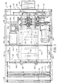
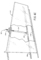
- a cushioning conversion machine 100 converts an essentially two-dimensional web of sheet-like stock material (the thickness thereof being negligible compared to the width and length thereof -- thus the phrase "essentially two-dimensional) into a three-dimensional cushioning product of a desired length.
- the preferred stock material consists of plural plies or layers of biodegradable and recyclable sheet-like stock material such as 30 to 50 pound Kraft paper rolled onto a hollow cylindrical tube to form a roll R of the stock material. More preferably, the stock material consists of two plies of paper which are intermittently glued together with small drops of glue up the center of the paper plies, the glue drops being spaced approximately one foot apart.
- the preferred cushioning product has lateral accordion-like or pillow-like portions and is connected, or assembled, along a relatively thin central band separating the pillow-like portions.
- the cushioning conversion machine 100 includes a housing 102 having a base plate or wall 103, side plates or walls 104, a downstream end plate or wall 105, a top cover 106, and a downstream cover, or wall 107.
- the base, side, and end walls 103-105 collectively form the machine's frame structure.
- the walls 103-107 of the housing 102 are each generally planar and rectangular in shape.
- the upstream edges of the base wall 103 and sides walls 104 are turned in to form, along with a top bar 108, a rectangular border defining a centrally located, and relatively large, rectangular stock inlet opening.
- the rectangular border may be viewed as an upstream end plate or wall extending perpendicularly from the upstream edge of the base wall 103.
- the end plate 105 extends perpendicularly from a location near, but inward from, the downstream end of the base wall 103 and defines a dunnage outlet opening.
- the downstream cover wall 107 is attached to the downstream edges of the base wall 103, with the side walls 104 and a downstream portion of the top cover 106 forming a box-like enclosure for certain components of the machine 100.
- the cover wall 107 may be selectively opened to provide access to these components.
- the downstream portion of the top cover preferably is fixedly secured in place while an upstream portion of the top cover may be in the form of a hinged door which may be opened to gain access to the interior of the housing and particularly the below mentioned forming assembly to facilitate loading of the stock material in a well known manner.
- the cushioning conversion machine 100 further includes a stock supply assembly 109, a forming assembly 110, a feeding/connecting assembly 111, a severing assembly 112, and a post-severing assembly 113.
- the stock supply assembly 109 supplies stock material to the forming assembly 110.
- the forming assembly 110 causes inward folding of lateral edge portions of the sheet-like stock material into an overlapping relationship.
- the feeding/connecting assembly 111 advances the stock material through the machine 100 and also crumples the folded over stock material to form a dunnage strip. As the dunnage strip travels downstream from the feeding/connecting assembly 111, the severing/aligning assembly 112 severs or cuts the dunnage strip into sections, or pads, of a desired length. The cut pads then travel through the post-severing assembly 113.
- the stock supply assembly 109 includes support brackets 114 which are laterally spaced apart and mounted to the upstream end of the machine's housing 102.
- the stock supply assembly 109 also includes first and second guide rollers 115 and 116 which are rotatably mounted between the support brackets 114, and a dancer roller 117 which is pivotally suspended from the support brackets 114 via swing arms 118.
- the paper then travels over and under the two guide rollers 115 and 116 to guide the paper into the forming assembly 110.
- the forming assembly 110 consists of a central plate 119, a pair of fold-down rollers 120, with folding elements 121 and 122 forming a chute-like passage, or chute, for lateral edge portions of the stock material.
- the central plate 119 is mounted on a pedestal 123 attached to the base wall 103 and slopes slightly downwardly, and tapers inwardly, going from the upstream end to the downstream end of the central plate.
- the rollers 120 are mounted on a shaft 124a extending between the ends of a pair of swing arms 124b that are pivotally connected at their opposite ends to a support bar 124c extending between the side walls 104.
- the folding elements 121 and 122 are mounted, in a cantilever-like fashion, from a mounting plate 125.
- the central portion of the paper (preferably about 1 / 3 of the paper width) will be positioned on the central plate 119 and its remaining lateral edge portions (preferably each about 1 / 3 the paper width) will be urged, or folded, downward by the rollers 120.
- the folding elements 121 and 122 the folding elements will fold the lateral edge portions of the paper inward one over the other, whereby they will overlap in a folded arrangement.
- This overlapped paper, or strip advances to the feeding/connecting assembly 111.
- the feeding/connecting assembly 111 includes a support structure 126, a wheel (or roller) network 127, a drive system 128, and a guide chute 129.
- the feeding/connecting components 126-129 feed the stock material, for example by pulling it from the stock supply assembly 109 and through the forming assembly 110.
- the feed/connecting assembly 111 longitudinally crumples the strip of stock material and then connects, or assembles, overlapped portions of stock material together to lock in a desired three-dimensional geometry of the resultant pad.
- the support structure 126 includes a pair of vertical side plates 130, and a horizontal cross bar 131.
- the downstream edges of the side plates 130 are coupled to the machine's housing 102, and more particularly to the end wall 105.
- the cross bar 131 extends between and is secured to the side plates 130.
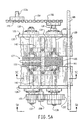
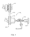
- the wheel network 127 includes a feed (or input) wheel 132, a support wheel 133 for the feed wheel 132, a compression (or output) wheel 134, a support wheel 135 for the compression wheel 134, and shafts 137-140 for each of the wheels 132-135, respectively.
- the lower wheels 132 and 134 are secured to the shafts 137 and 139, respectively, and the upper wheels 133 and 135 are rotatably mounted on their shafts 138 and 140, respectively.
- the lower shafts 137 and 139 are positively driven by the drive system 128 to rotate the lower wheels 132 and 134 which will in turn rotate the upper, or "idler", wheels 133 and 135.
- the lower shafts 137 and 139 extend between, and are rotatably journalled in the support side plates 130. (See Figs. 3 and 5A-5C.)
- the upper shaft 140 extends between the side plates 130 and has its opposite ends positioned within a vertical guide slot 130a in the corresponding side plate 130. (See Figs. 3 and 5A-5B.)
- the upper shaft 138 has opposite ends thereof terminating short of the side plates.
- a pair of laterally spaced apart shaft connectors 142 are connected between the upper shafts 138 and 140, and each shaft connector is attached, at about the middle thereof, to the lower end of a respective suspension pin or member 143.
- Each pin extends vertically though a respective guide opening in the cross bar 131 and carries thereon a compression spring 144 interposed between the cross bar and shaft connector.
- the upper or “idler” wheels 133 and 135 will be resiliently biased towards the corresponding lower wheels 132 and 134, while being able to vertically “float” relative thereto during operation of the machine 100.
- the wheels 132 and 133 are both generally cylindrical in shape.
- the feed wheel 132 includes a middle portion 145 separating opposite axial end portions 146.
- the middle portion 145 is in the form of an annular groove which, for example, may have an approximately rectangular (as shown) or semi-circular cross section.
- the cylindrical periphery of the opposite axial end portions 146 is interrupted by flat faces 147.
- the flat faces 147 on one end portion 146 are staggered relative to the flat faces on the other end portion 146. In other words, the flat faces 147 on one axial end portion 146 are aligned with the "non-flat", or arcuate, knurled areas 148 on the other axial end portion 146.
- the support wheel 133 for the feed wheel 132 also includes a middle portion 149 separating opposite axial end portions 150.
- the middle portion 149 is in the form of a radially outwardly protruding annular rib which is preferably rounded at its radial outer side, while the end portions 150 have knurled radial outer surfaces.
- the radial outer surfaces of one or both of the wheels 132 and 133, or portions thereof, may be manufactured from an elastomeric material, such as rubber (neoprene or urethane) thereby reducing the cost and complexity of the wheels while still providing a high level of friction-enhancement for relatively slip free engagement with the stock material.
- the wheels 134 and 135 are also both generally cylindrical in shape.
- the compression wheel 134 includes a middle portion 151 separating opposite axial end portions 152.
- the middle portion 151 is radially relieved and has a smooth radial surface.
- the end portions 152 are ribbed to form rectangular, circumferentially spaced apart teeth.
- the support wheel 135 for the compression wheel 134 includes a continuous, knurled outer diameter surface.
- the radial outer surfaces of one or both of the wheels 134 and 135, or portions thereof, may again be manufactured from an elastomeric material such as rubber (neoprene or urethane) thereby reducing the cost and complexity of the wheels while still providing a high level of friction-enhancement for relatively slip free engagement with the stock material.
- an elastomeric material such as rubber (neoprene or urethane)
- the drive system 128 for the feeding/connecting assembly 111 includes an electric motor 153, and motion-transmitting elements 154-159 (Figs. 3, 3A and 5A).
- the motor 153 is mounted to the base plate 103 on one side of the forming assembly 110.
- the motion-transmitting elements transfer the rotational power of the motor 153 to the wheel network 127, or more particularly the lower shafts 137 and 139.
- the motion-transmitting elements include a drive chain 154 and sprockets 155 and 156.
- the sprocket 155 is secured to an output shaft 153a of a speed reducing gear box 153b driven by the motor 153 (See Fig. 1), and the sprocket 156 is secured to the compression wheel shaft 139.
- the drive chain 154 is trained around the sprockets 155 and 156 to rotate the compression wheel shaft 139.
- the motion transmitting elements 157-159 are gears forming a gear train between the compression wheel shaft 139 and the feed wheel shaft 137.
- the gear 157 is secured to the end of the compression wheel shaft 139 opposite the sprocket 156, the gear 158 is rotatably mounted to support side plate 130, and the gear 159 is secured to an adjacent end of the feed wheel shaft 137.
- the gears are selected so that the shaft 137 (and thus the feed wheel 132) is rotating at a faster feed rate than the shaft 139 (and thus the compression wheel 134).
- the set speed ratio is on the order of about 1.7:1 to about 2.0:1.
- the guide chute 129 extends from the exit end of the forming assembly 110 to the outlet opening in the housing end wall 105.
- the guide chute 129 can be seen to be substantially rectangular in cross-section.
- the upstream bottom and/or side edges of the chute preferably flare outwardly to form a funnel or converging mouth inlet 160 (Fig. 5B).
- the top and bottom walls of the guide chute 129 each include an opening 161 through which the wheels 132-135 extend into the interior of the guide chute (Figs. 5A-5C). It will be appreciated that the cross-sectional dimensions (i.e., width and height) of the guide chute 129 approximate the cross-sectional dimensions of the cushioning product.
- the strip formed in the forming assembly 110 is urged into the guide chute 129 through its funnel inlet 160 whereat it is engaged and fed forwardly (or downstream) by the feed wheel 132 and its support wheel 133.
- the staggered arrangement of the flat faces 147 on the end portions 146 of the wheel 133 will cause the strip to be fed alternately from each side of its longitudinal axis, instead of just being pulled only axially. That is, the strip will be fed alternately from each side of its longitudinal axis, instead of being pulled only axially.
- This advance by successive pulls from one side and then the other side back and forth makes it possible to have at the center a surplus of paper with respect to its flat configuration, this surplus being generated by the rib 159 fitting in the mating groove in the wheel 132.
- the strip is then engaged by the compression wheel 134 and its support wheel 135. Because the wheels 134 and 135 are rotating at a slower speed than the wheels 132 and 133, the strip is longitudinally crumpled between the upstream and downstream pairs of wheels with the latter compressing folds in the strip. (For further information regarding an assembly similar to the feeding/connecting assembly 111, reference may be had to European Patent Application No. 94440027.4, filed April 22, 1994 and published on November 2, 1995 under Publication No. 0 679 504 A1, which is hereby incorporated herein by reference.) The strip then exits the guide chute 129 and passes through the dunnage outlet opening in the end wall 105.
- the illustrated severing assembly 112 severs its leading portion into a desired length.
- the illustrated severing assembly 112 includes cutting components 162 preferably powered by an electric motor 163 (Fig. 1).
- the cutting components 162 are mounted on the downstream surface of the end wall 105 are contained within the enclosure closed by the downstream cover 107.
- the severing motor 163 is mounted on the base wall 103 on the side of the forming assembly opposite the feed motor 153. (See Figs. 1 and 2.)
- a suitable severing assembly is disclosed in U.S. Patent Application No. 08/188,305, which is hereby incorporated by reference.
- the cut sections of dunnage then travel through the post-severing assembly 113.
- the post-severing assembly 113 is mounted to the downstream cover 107.
- the inlet and outlet of the assembly 113 are aligned with the dunnage outlet opening in the end wall 105.
- the post-severing assembly 113 is rectangular in cross-sectional shape and flares outwardly in the downstream direction. As the cut section of the dunnage strip, or pad, emerges from the outlet of the assembly 113, the pad is ready for use as a cushioning product.
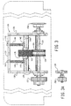
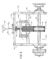
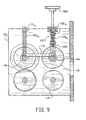
- FIGs. 8 and 9 Another modified form of the feeding/connecting assembly is shown in Figs. 8 and 9 which is designed to provide for a convenient, and even dynamic, selective change in the biasing force between the compression wheel 134 and its support wheel 135.
- the support structure 129 t of the wheel network 127 t includes a pair of horizontal cross bars 131a t and 131b t which extend between, and are secured to, the side plates 130.
- the cross bar 131a t is vertically aligned with the shaft 138 and the cross bar 131b t is vertically aligned with the shaft 140.
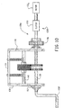
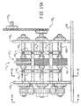
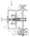
- FIG. 20 and 21 Another modified form of the feeding/connecting assembly is shown in Figs. 20 and 21, this assembly incorporating a modified drive system 128 x .
- the feed wheel shaft 137 (and thus the feed wheel 132 and its support wheel 133) is directly driven by the motor 153 at a constant speed.
- the compression wheel shaft 139 (and thus the compression wheel 134 and its support wheel 135) are driven intermittently, rather than continuously, by an indexing device 1040 which replaces the gear train 157-159.
- the indexed wheels 134 and 135 are not rotating, the stock material is crumpled as the rotating wheels 132 and 133 continue to advance stock material downstream.
- the indexed wheels 134 and 135 are rotating, the stock material will be emitted from the feeding/connecting assembly.
- the indexing device 1040 is a conventional "Geneva" gear mechanism and, in the illustrated device, the compression wheel 134 rotates a quarter of a revolution for every half revolution of the feed wheel 132.
- the device 1040 includes a driver disk 1042 mounted to the support wall 130, a cam pin 1041 mounted to the driver disk 1042, a gear 1043 coupled to the end of the feed shaft 137, and a four-slotted disk 1044 coupled to the end of the compression wheel shaft 138.
- the driver disk is indexed with the compression shaft 139 so that upon every half revolution of the feed wheel shaft 137, the driver disk 1042 will also make one revolution. As the driver disk 1042 makes one revolution, it will cause the four-slotted disk 1044 to rotate a quarter of a revolution via the cam pin 1041.
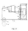
- FIG. 19A - 19C Another modified form 111 y of the feeding/connecting assembly is shown in Figs. 19A - 19C.
- the wheel network 127 y of this assembly includes a "stretching assembly" comprised of a stretch wheel 1050, its support wheel 1051, and corresponding shafts 1052 and 1053.
- the wheels 1050 and 1051 are rotated at a faster feed rate speed than the wheels 134 and 135 whereby the strip will be "stretched" prior to passing through the outlet opening in the end wall 105.
- the wheels 1050 and 1051 may be essentially identical in design and size as the wheels 134 and 135, respectively.
- a cushioning conversion machine 200 converts sheet-like stock material into a three-dimensional cushioning product of a desired length.
- the preferred stock material for the machine 200 consists of plural plies or layers of biodegradable and recyclable sheet-like stock material such as 30 to 50 pound Kraft paper rolled onto a hollow cylindrical tube to form a roll R of the stock material.
- the stock material would preferably consist of three plies of paper and, in any event, would not be intermittently glued together.
- the preferred cushioning product of the machine 200 has lateral accordion-like or pillow-like portions and is connected, or assembled, along a relatively thin central band separating the pillow-like portions.
- the machine 200 is similar to the machine 100 discussed above, and includes an essentially identical housing 202, feeding/connecting assembly 211, severing assembly 212, and post-severing assembly 213. However, the stock supply assembly 209 and the forming assembly 210 of the machine 200 differ from these assemblies in the machine 100.
- the stock supply assembly 209 includes two support brackets 214 which are laterally spaced apart and mounted to the machine's frame, or more particularly the upstream wall (or rectangular border) 208.
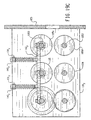
- the stock supply assembly 209 also includes a sheet separator 216, and a constant-entry roller 218.
- the sheet separator 216 includes three vertically spaced rollers which extend between, and are connected to, the support brackets 214. (The number of separator rollers corresponds to the number of plies or layers of the stock material whereby more or less rollers could be used depending on the number of layers.)
- the constant-entry roller 218 also extends between, and is connected to, the support brackets 214.
- the paper As the paper is unwound from the supply roll R, it travels over the constant-entry roller 218 and into the separating device 216.
- the separating device In the separating device, the plies or layers of the stock material are separated by the separator rollers and this "pre-separation" is believed to improve the resiliency of the produced cushioning product.
- the constant-entry roller 218 provides a non-varying point of entry for the stock material into the separator 216 regardless of the diameter of the roll R. (Details of a similar stock supply assembly are set forth in U.S. Patent No. 5,322,477, the entire disclosure of which is hereby incorporated by reference.)
- the forming assembly 210 includes a shaping chute 219 and a forming member 220.
- the shaping chute 219 is longitudinally converging in the downstream direction and is positioned in a downstream portion of the enclosure formed by the machine's housing. Its entrance is outwardly flared in a trumpet-like fashion and its exit is positioned adjacent the feeding/connecting assembly 211.
- the chute 219 is mounted to the housing at the bottom wall 103 and at 221.
- the forming member 220 has a "pinched U” or “bobby pin” shape including a bight portion joining upper and lower legs.
- the lower leg extends to a point approximately coterminous with the exit end of the shaping chute 219.
- the rearward portion of the forming member 220 preferably projects rearwardly of the entry end of the shaping chute by approximately one-half its overall length.
- the radius of the rounded base or bight portion is approximately one-half the height of the mouth of the shaping chute. This provides for a smooth transition from the separating device 216 to the forming member and then into the shaping chute.
- the lower leg 220a of the forming member 220 extends generally parallel to the bottom wall 219a of the shaping chute 219.
- the relative inclination and spacing between the lower leg of the forming member and bottom wall of the shaping chute may be adjusted as needed to obtain proper shaping and forming of the lateral edges of the stock material .
- Such adjustment may be effected and then maintained by an adjustment device 223 which, as best shown in Fig. 6C, extends between the legs of the forming member at a point midway along the length of the lower leg, it being noted that the upper leg may be shorter as only sufficient length is needed to provide for attachment of the top wall of the shaping chute.
- the adjustment device 223 includes a rod 224 having a lower end attached to the lower leg of the forming member 220 by a rotation joint 225 (such as a ball-and-socket joint).
- the upper threaded end of the rod 224 extends through a threaded hole in the top wall of the shaping chute as well as through a threaded hole in a upper leg of the forming member 220 and is held in place by a nut 224a secured to the shaping chute 219.
- the top of the threaded rod is turned the appropriate direction.
- the rod's top may be provided with a screwdriver slot or wrench flats, to easily accomplish this turning with standard tools.
- chutes and shaping members 220 are set forth in U.S. Application No. 08/487,182, the entire disclosure of which is hereby incorporated by reference.
- other chutes and shaping members are possible with, and contemplated by, the present invention.
- the chutes and/or shaping members set forth in U.S. Patent Nos. 4,026,198; 4,085,662; 4,109,040; 4,717,613; and 4,750,896, could be substituted for the forming chute 219 and/or the shaping member 220.
- the shaping chute 219 As the stock material passes through the shaping chute 219, its lateral end sections are rolled or folded inwardly into generally spiral form and are urged inwardly toward one another so that the inwardly rolled edges form a pillow-like portions of stock material disposed in lateral abutting relationship as they emerge from the exit end of the shaping chute.
- the forming member 220 coacts with the shaping chute 219 to ensure proper shaping and forming of the paper, the forming member being operative to guide the central section of the stock material along the bottom wall of the chute 219 for controlled inward rolling of the lateral side sections of the stock material.
- the rolled stock material, or strip then travels to the feeding/connecting assembly 211.
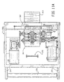
- FIG. 11A, 11B, 11C and 12 Another cushioning conversion machine 300, formed from modular units 300a and 300b according to the present invention, is shown in Figs. 11A, 11B, 11C and 12.
- the machine 300 converts sheet-like stock material into a three-dimensional cushioning product of a desired length.
- the preferred cushioning product of the machine 300 has lateral crumpled pillow-like portions and is connected, or assembled, along a central band separating the pillow-like portions.
- the preferred stock material for the machine 300 consists of plural plies or layers of biodegradable and recyclable sheet-like stock material such as 30 to 50 pound Kraft paper rolled onto a hollow cylindrical tube to form a roll R of the stock material.
- the first modular unit 300a includes a housing 302a similar to the downstream portion of the housing 102 of the machine 100.
- a feeding/connecting assembly 311, a severing assembly 312 and a post-severing assembly 313, which are essentially identical to the corresponding assemblies in the machine 100, are mounted to the housing 302a in the same manner as they are mounted the downstream portion of the housing 102.
- an expanding device 370 occupies the space in the machine housing 102 that had been occupied by the forming assembly 110 and requires less space.
- a guide roller 372 is mounted to the upstream end of the housing 302a via brackets 374.
- the separating member 380 includes a transverse support 393 and fold expansion elements 395 at opposite ends of the transverse support 393 that are relatively thicker than the transverse support 393, with respect to the narrow dimension of the stock material.
- the mounting member 378 is formed by a rod or tube, and the fold expansion elements are formed by rollers supported for rotation on the transverse support at opposite ends thereof.
- the transverse support 393 is attached near one end thereof to the adjacent end portion 385 of mounting member 381 for support in cantilevered fashion.
- the expanding device 373 is designed for use with flat-folded stock material which is formed by the second modular unit 300b.
- the layers of the stock material (formed by the edge and central portions of the ply or plies) travel through the expanding device 373. More particularly, the central section of the folded stock material travels over the sides of the rollers 395 opposite the mounting arm 381, while the inner edge portion of the stock material travels in the narrow V-shape or U-shape slot formed between the transverse support 393 and the mounting arm 381 and the other or outer edge portion of the travels over the side of the mounting arm 381 furthest the separating member 380.
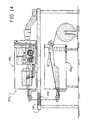
- the second modular unit 300b includes a housing 302b similar to the upstream portion of the housing 102 of the machine 100. (See Fig. 12.)
- a forming assembly 310 is essentially identical to, and is mounted to the housing 302b in the same manner as, the corresponding assembly in the machine 100.
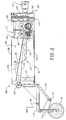
- a stock roll R may be supported by a floor mounted stand or stock roll support 2002.
- a guide roller 398 is mounted to a downstream end of the housing 302a via bracket 399.
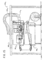
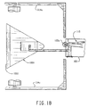
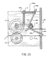
- FIG. 15 Another modified version 2000 w of the packaging system is shown in Fig. 15.
- the first unit 300a is stacked on top of the second unit 300b below an elevated (when compared to tables 2001 and 2001 w ) table 2001 w .
- the post-severing assembly 313 w is curved upwardly towards an opening 2003 w in the table whereby the cut section of cushioning will be deposited on the table top. This arrangement allows the table top to be clear of all machine components during the production of cushioning products.
Claims (11)
- Eine Polsterumformungsmaschine zur Herstellung eines Posterproduktes durch Umformen eines im Wesentlichen zweidimensionalen Gewebes aus bahnförmigem Ausgangsmaterial mit zumindest einer Lage in ein dreidimensionales Polsterprodukt, wobei die Maschine eine Zuführ/Verbindeanordnung umfasst, gekennzeichnet durch einen Steuermechanismus, der einem Bediener ermöglicht, selektiv eine Eigenschaft des Polsterproduktes zu variieren, das die Maschine nach Bedarf produziert, wobei die Eigenschaft die Dichte, die Kompaktheit, die Polsterungsfähigkeit, die Steifheit und/oder der Ertrag aus einer gegebenen Menge von Ausgangsmaterial des Polsterproduktes ist und weiterhin gekennzeichnet durch ein Gehäuse, das vom Ausgangsmaterial durchlaufen wird, und wobei der Steuermechanismus ein erreichbares Steuerglied außerhalb des Gehäuses aufweist, um eine einfache Einstellung der Eigenschaft des Polsterproduktes durch den Bediener zu ermöglichen; und weiterhin dadurch gekennzeichnet, dass das Steuerglied dazu eingesetzt werden kann, um die relative Geschwindigkeit der stromaufwärtigen und stromabwärtigen Komponenten der Zuführ-/Verbindeanordnung einzustellen; oder dazu geeignet ist, die Größe des Klemmdruckes zu variieren, der durch gegenüberliegende Glieder der Zuführ/Verbindeanordnung aufgebracht wird, zwischen denen das Ausgangsmaterial durchgeführt und geklemmt wird.
- Eine Polsterumformungsmaschine gemäß einem der vorherigen Ansprüche, wobei die Zuführ/Verbindeanordnung das Ausgangsmaterial aus seiner Quelle entlang eines Pfades weiterbewegt, das Ausgangsmaterial zerknittert und das zerknitterte Ausgangsmaterial verbindet, um einen Polsterstreifen zu erzeugen.
- Eine Polsterumformungsmaschine gemäß dem vorherigen Anspruch, wobei die Zuführ-/Verbindeanordnung stromaufwärtige und stromabwärtige Komponenten umfasst, welche entlang des Pfades des Ausgangsmaterials angeordnet sind; wobei zumindest die stromaufwärtige Komponente angetrieben wird, um das Ausgangsmaterial mit einer Rate zu der stromabwärtigen Komponente weiterzubewegen, die schneller ist, als das bahnförmige Ausgangsmaterial die stromabwärtige Komponente durchlaufen kann, um das Ausgangsmaterial dazwischen zu zerknittern, zur Bildung eines Polsterstreifens.
- Eine Polsterumformungsmaschine gemäß einem der Ansprüche 1 bis 3, wobei die Zuführ-/Verbindeanordnung gegenüberliegende Glieder aufweist, zwischen denen das Ausgangsmaterial durchläuft und durch die es mit einem Klemmdruck geklemmt wird, und wobei der Steuermechanismus ein Spannungssteuermechanismus ist, um das Maß des Klemmdrukkes einzustellen, der durch die gegenüberliegenden Glieder auf das Ausgangsmaterial aufgebracht wird, und wobei, wenn von Anspruch 3 abhängig, zumindest eine der stromaufwärtigen und stromabwärtigen Komponenten die gegenüberliegenden Glieder umfasst.
- Eine Polsterumformungsmaschine gemäß Anspruch 4, wenn dieser von Anspruch 3 abhängig ist, wobei der Spannungssteuermechanismus die Größe des Klemmdruckes einstellt, der durch die gegenüberliegenden Glieder der stromabwärtigen Komponente auf das Ausgangsmaterial aufgebracht wird, unabhängig von dem Klemmdruck, der auf das Ausgangsmaterial durch die gegenüberliegenden Glieder der stromaufwärtigen Komponente aufgebracht wird.
- Eine Umformungsmaschine gemäß Anspruch 4 oder Anspruch 5, wobei der Spannungssteuermechanismus eine Vorspanneinrichtung aufweist, die federnd eines der gegenüberliegenden Glieder in Richtung des anderen vorspannt und ein Einstellelement aufweist, zur Einstellung der Vorspannkraft, die durch das Vorspanngerät auf eines der gegenüberliegenden Glieder aufgebracht wird, wobei das Einstellgerät operativ mit dem Steuerglied verbunden ist.
- Eine Umformungsmaschine gemäß Anspruch 3, wobei der Steuermechanismus einen einstellbaren Geschwindigkeitssteuermechanismus umfasst, zur Veränderung des Verhältnisses der Zuführgeschwindigkeiten der stromaufwärtigen und stromabwärtigen Zuführkomponenten, wodurch eine Eigenschaft des Polsterstreifens variiert werden kann.
- Eine Umformungsmaschine nach dem vorherigen Anspruch, wobei der verstellbare Geschwindigkeitssteuermechanismus eines der folgenden Elemente umfasst:einen Schnellwechselgetriebesatz;eine variable Geschwindigkeitssteuerung für zumindest einen der entsprechenden Motoren, die die stromabwärtigen und stromaufwärtigen Komponenten antreiben;ein Rollensystem mit variabler Übersetzung.
- Eine Umformungsmaschine gemäß Anspruch 3 oder jedem Anspruch, welcher davon abhängig ist, wobei die Zuführ-/Verbindeanordnung weiterhin eine Streckkomponente stromabwärtig von der stromabwärtigen Komponente aufweist, die dazu dient, den Polsterstreifen mit einer Rate weiterzubewegen, welche schneller ist, als die Rate, mit der das Ausgangsmaterial die stromabwärtige Komponente verlässt, um eine Längsstreckung des Polsterstreifens zu bewirken.
- Eine Umformungsmaschine gemäß dem vorherigen Anspruch, wobei der Steuermechanismus einen einstellbaren Geschwindigkeitssteuermechanismus umfasst, zur Veränderung der Geschwindigkeit, mit der die Streckkomponente das Material weiterbewegt.
- Die Verwendung einer Umformungsmaschine gemäß einem der vorherigen Ansprüche, um ein im Wesentlichen zweidimensionales Gewebe bahnförmigen Ausgangsmaterials von zumindest einer Lage in ein dreidimensionales Polsterprodukt umzuformen, wobei ein Bediener den Steuermechanismus verwendet, um selektiv eine Eigenschaft eines durch die Maschine produzierten Polsterproduktes zu verändern.
Applications Claiming Priority (4)
| Application Number | Priority Date | Filing Date | Title |
|---|---|---|---|
| US49695P | 1995-06-26 | 1995-06-26 | |
| US600496 | 1995-06-26 | ||
| US496P | 1995-06-26 | ||
| PCT/US1996/010899 WO1997001434A2 (en) | 1995-06-26 | 1996-06-26 | Cushioning conversion machine and method |
Publications (3)
| Publication Number | Publication Date |
|---|---|
| EP0886573A2 EP0886573A2 (de) | 1998-12-30 |
| EP0886573A4 EP0886573A4 (de) | 1998-12-30 |
| EP0886573B1 true EP0886573B1 (de) | 2003-02-19 |
Family
ID=21691766
Family Applications (1)
| Application Number | Title | Priority Date | Filing Date |
|---|---|---|---|
| EP96923446A Expired - Lifetime EP0886573B1 (de) | 1995-06-26 | 1996-06-26 | Vorrichtung zur herstellung von polsterelementen und deren verwendung |
Country Status (6)
| Country | Link |
|---|---|
| US (5) | US6019715A (de) |
| EP (1) | EP0886573B1 (de) |
| AU (1) | AU6395396A (de) |
| CA (1) | CA2225720A1 (de) |
| DE (1) | DE69626315T2 (de) |
| WO (1) | WO1997001434A2 (de) |
Families Citing this family (56)
| Publication number | Priority date | Publication date | Assignee | Title |
|---|---|---|---|---|
| CA2225720A1 (en) * | 1995-06-26 | 1997-01-16 | Ranpak Corp. | Cushioning conversion machine and method |
| AU3964897A (en) | 1996-07-26 | 1998-02-20 | Ranpak Corp. | Cushioning conversion system |
| DE888878T1 (de) * | 1997-06-30 | 2000-03-02 | Ranpak Corp | Polsterumwandlungsmaschine und Verpackungsanlage |
| US6402674B1 (en) | 1997-12-23 | 2002-06-11 | Ranpak Corp. | Cushioning conversion system and method with dancer roller cart |
| EP1047545B1 (de) | 1998-01-12 | 2003-06-04 | Ranpak Corp. | Maschine und verfahren zum herstellen von polsterelementen |
| US6210310B1 (en) | 1998-01-12 | 2001-04-03 | Ranpak Corp. | Cushioning conversion machine and method with enhanced stock separation and forming |
| US6179765B1 (en) * | 1998-10-30 | 2001-01-30 | Ft Acquisition, L.P. | Paper dispensing system and method |
| EP1044794A3 (de) | 1998-12-09 | 2003-07-23 | Ranpak Corp. | Polsterumwandlungsmaschine und Verfahren zu deren Verwendung mit mehreren Eingangsrollenführungen |
| US6174273B1 (en) * | 1998-12-18 | 2001-01-16 | Ranpak Corp. | Cushioning conversion machine with tension control |
| US7083560B2 (en) | 1999-09-09 | 2006-08-01 | Ranpak Corp. | Cushioning conversion machine having heavy duty characteristics |
| FR2808726B1 (fr) * | 2000-05-09 | 2002-12-13 | Naturembal Sa | Machine de fabrication de bande de rembourrage matelassee |
| KR100743955B1 (ko) * | 2000-06-09 | 2007-07-30 | 랜팩 코포레이션 | 이동 그리퍼가 있는 깔개 전환 장치, 그 방법 및 제품 |
| US6632165B1 (en) * | 2000-11-01 | 2003-10-14 | Guy Letourneau | Paper conversion dispenser machine |
| WO2003089163A2 (en) * | 2002-04-22 | 2003-10-30 | Ranpak Corp. | Dunnage converter system |
| EP1648689B1 (de) * | 2003-07-07 | 2007-10-31 | Ranpak Corp. | Polsterumarbeitungsvorrichtung mit trennvorrichtung und verfahren |
| ATE411893T1 (de) * | 2005-03-23 | 2008-11-15 | Ranpak Corp | Selektiv zerreissbares rohrmaterial für eine polstermaschine und verfahren |
| US20070117703A1 (en) * | 2005-11-22 | 2007-05-24 | Sealed Air Corporation | Machine and method for converting a web of material into dunnage |
| US8167783B2 (en) * | 2006-04-11 | 2012-05-01 | Pack-Tiger Gmbh | Machine for the manufacture of paper padding |
| EP2990193B1 (de) * | 2006-06-10 | 2019-07-17 | Ranpak Corp. | Kompakter packmaterialumwandler |
| KR101141711B1 (ko) * | 2006-08-09 | 2012-05-04 | 삼성테크윈 주식회사 | 테이프 배출장치 및 테이프 배출방법 |
| US7662080B2 (en) * | 2006-10-12 | 2010-02-16 | Bowe Bell & Howell | Crease roller apparatuses and methods for using same |
| DE102006054593A1 (de) * | 2006-11-20 | 2008-05-21 | Pack-Tiger Gmbh | Maschine zur Herstellung von Papier-Polstern |
| DE102006059638A1 (de) * | 2006-12-18 | 2008-06-19 | Pack-Tiger Gmbh | Maschine zur Herstellung von Papier-Polstern |
| EP2185351A4 (de) * | 2007-08-31 | 2011-12-14 | Pregis Innovative Packaging | Packmaterialgerät mit bogenzuführung |
| WO2009042664A2 (en) | 2007-09-24 | 2009-04-02 | Ranpak Corp. | Dunnage conversion machine, method and dunnage product |
| US20090258775A1 (en) * | 2008-04-11 | 2009-10-15 | Chan Simon C S | Apparatus, systems and methods for producing cushioning material |
| WO2010006165A2 (en) * | 2008-07-09 | 2010-01-14 | Ranpak Corp. | Dunnage conversion with yield-enhanced paper |
| US20110218089A1 (en) * | 2008-11-17 | 2011-09-08 | Ranpak Corp. | Compact dunnage conversion machine |
| WO2010078560A1 (en) | 2009-01-02 | 2010-07-08 | Nuevopak International Limited | Off-set gears and methods of using off-set gears for producing cushioning material |
| WO2011025915A1 (en) | 2009-08-28 | 2011-03-03 | Pregis Innovative Packaging, Inc. | Flexible dunnage handler |
| US10035320B2 (en) * | 2009-08-28 | 2018-07-31 | Pregis Innovative Packaging Llc | Crumpling mechanism for creating dunnage |
| US8388508B2 (en) | 2009-08-28 | 2013-03-05 | Pregis Innovative Packaging, Inc. | Crumpling mechanism for creating dunnage |
| US10220589B2 (en) * | 2009-08-28 | 2019-03-05 | Pregis Innovative Packaging Llc | Dunnage system with variable accumulator |
| US8267848B2 (en) * | 2009-08-28 | 2012-09-18 | Pregis Innovative Packaging, Inc. | Dunnage device and handler disengagement |
| US8303475B2 (en) | 2009-08-28 | 2012-11-06 | Pregis Innovative Packaging, Inc. | Vertically arranged dunnage apparatus |
| US20110053749A1 (en) * | 2009-08-28 | 2011-03-03 | Pregis Innovative Packaging, Inc. | Dunnage apparatus with pivoting sheet supply |
| US8845504B2 (en) | 2009-08-28 | 2014-09-30 | Pregis Innovative Packaging, Inc. | Reconfigurable dunnage handler |
| GB2487771A (en) * | 2011-02-04 | 2012-08-08 | Easypack Ltd | Dunnage making |
| DE102012218679A1 (de) * | 2012-10-12 | 2014-04-17 | Storopack Hans Reichenecker Gmbh | Vorrichtung zur Herstellung eines Polsters aus Papier |
| DE102013015875A1 (de) * | 2013-09-23 | 2015-03-26 | Sprick Gmbh Bielefelder Papier- Und Wellpappenwerke & Co. | Perforationswerkzeug für eine Vorrichtung zum maschinellen Fertigen eines Füllmaterialerzeugnisses und Vorrichtung zum maschinellen Fertigen eines Füllmaterialerzeugnisses |
| US9475666B2 (en) * | 2013-11-04 | 2016-10-25 | Kucharco Corporation | Full contact teter dispension for controlling deployment of expandable web material |
| US9505574B2 (en) * | 2013-11-04 | 2016-11-29 | Kucharco Corporation | Traction control system for expansion and deployment of compact tightly wound paper with die cut slits |
| US20150352802A1 (en) * | 2014-06-09 | 2015-12-10 | Storopack, Inc. | Protective packaging work station |
| DE102014016874A1 (de) * | 2014-11-14 | 2016-05-19 | Sprick Gmbh Bielefelder Papier- Und Wellpappenwerke & Co. | Vorrichtung zum maschinellen Fertigen eines Füllmaterialerzeugnisses |
| US9802215B2 (en) * | 2015-02-10 | 2017-10-31 | The Boeing Company | Method and system for applying a coating |
| US10397301B2 (en) * | 2015-09-08 | 2019-08-27 | International Business Machines Corporation | Web page view customization |
| CN107215006A (zh) * | 2016-03-21 | 2017-09-29 | 陈泽生 | 纸垫制作系统所需的纸材料、装置、系统和方法 |
| US20200180256A1 (en) | 2016-06-30 | 2020-06-11 | Ranpak Corp. | Dunnage conversion machine and method |
| DE102016114342A1 (de) * | 2016-08-03 | 2018-02-08 | Storopack Hans Reichenecker Gmbh | Verfahren und Vorrichtung zum Herstellen eines Polsterungserzeugnisses sowie Polsterungserzeugnis |
| EP3526028B1 (de) * | 2016-10-11 | 2020-12-02 | Ranpak Corp. | Packmaterialumwandlungsmaschine und -verfahren |
| CN109952193B (zh) * | 2016-10-11 | 2021-11-30 | 希悦尔公司 | 用于产生空隙填充包装材料的机器和方法 |
| WO2018112286A1 (en) | 2016-12-15 | 2018-06-21 | Sealed Air Corporation (Us) | Packaging method |
| WO2018175742A1 (en) * | 2017-03-24 | 2018-09-27 | Ranpak Corporation | Dunnage conversion machine having a variable spacing for expandable slit-sheet stock material |
| US11034121B2 (en) * | 2017-05-11 | 2021-06-15 | Pregis Innovative Packaging Llc | Dunnage apparatus carton filler |
| US20190105865A1 (en) * | 2017-10-11 | 2019-04-11 | Adam Kelley | Machine for converting spooled material into dunnage |
| DE102019001185A1 (de) * | 2019-02-18 | 2020-08-20 | Sprick Gmbh Bielefelder Papier- Und Wellpappenwerke & Co. | Vorrichtung zum Fertigen eines Verpackungserzeugnisses und Baukasten für das Ausbilden einer Vorrichtung |
Family Cites Families (50)
| Publication number | Priority date | Publication date | Assignee | Title |
|---|---|---|---|---|
| US390442A (en) * | 1888-10-02 | Paper-box-making machinery | ||
| US2396128A (en) * | 1943-05-26 | 1946-03-05 | Robaczynski Ladislaus | Driving mechanism for machine tables |
| US2537026A (en) * | 1948-01-08 | 1951-01-09 | Delwin A Brugger | Device for forming flexible packing and cushioning elements |
| US2786399A (en) * | 1952-03-06 | 1957-03-26 | Veyne V Mason | Formation of crumpled sheet material filter elements and the like |
| NL104672C (de) * | 1954-07-07 | |||
| DE1432502A1 (de) * | 1964-04-18 | 1969-02-13 | Freudenberg Carl Fa | Vorrichtung zum Raffen von Wursthuellen |
| DE1479312B2 (de) * | 1964-09-15 | 1972-04-13 | Galimberti, Gianfranco, Mailand (Italien) | Maschine zum anbringen von teilen an und/oder bearbeiten der innenwand eines kontinuierlich bewegten schlauches |
| US3717074A (en) * | 1967-12-04 | 1973-02-20 | Hoerner Waldorf Corp | Deadened crease |
| US3509798A (en) * | 1968-02-07 | 1970-05-05 | Arpax Co | Mechanism and method for producing cushioning dunnage |
| US3485145A (en) * | 1968-03-18 | 1969-12-23 | Canadian Ind | Apparatus for forming gusseted tubing |
| US3540076A (en) * | 1968-10-29 | 1970-11-17 | Union Carbide Corp | Pilot device |
| US3613522A (en) * | 1969-09-12 | 1971-10-19 | Arpax Co | Method of producing cushioning dunnage |
| GB1358048A (en) | 1970-09-04 | 1974-06-26 | Saba Gmbh | Adjusting device for tuner units |
| US4026198A (en) * | 1975-05-01 | 1977-05-31 | Ranpak Corporation | Cushioning dunnage mechanism, transfer cart therefor, and method |
| US4280690A (en) * | 1978-07-21 | 1981-07-28 | James Hill | Collator |
| US4355437A (en) * | 1980-05-08 | 1982-10-26 | Teepak, Inc. | Quick change drive for shirring machine control shaft |
| US4381107A (en) * | 1980-07-28 | 1983-04-26 | John W. Armiger | Cutting and collating method and apparatus for tickets |
| CH659451A5 (de) * | 1982-12-13 | 1987-01-30 | Ferag Ag | Mehrblaettriges, aus ineinanderliegenden gefalzten bogen bestehendes druckprodukt. |
| US4717613A (en) * | 1984-05-10 | 1988-01-05 | Ranpak Corporation | Mechanism and method for producing cushioning dunnage |
| US4674375A (en) * | 1984-10-03 | 1987-06-23 | G.B.R. Ltd. | Mechanism for slitting and merging sheets |
| US4750896A (en) * | 1985-10-28 | 1988-06-14 | Ranpak Corp. | Method and mechanism for producing cushioning dunnage product |
| US4619635A (en) * | 1985-11-04 | 1986-10-28 | Ranpak Corp. | Automatic feed circuit for dunnage converter |
| DE3544284A1 (de) * | 1985-12-17 | 1987-06-25 | Cavagna Elio Srl | Vorrichtung zum praegen und/oder rillen von blatt- oder bandfoermigem material |
| US4783949A (en) * | 1988-03-07 | 1988-11-15 | Culbro Machine Systems | Flexible adjustable wedge |
| DE3903382A1 (de) * | 1989-02-04 | 1990-08-09 | Franz Sperner | Schuettfaehiges packmaterial |
| US4968291A (en) * | 1989-05-03 | 1990-11-06 | Ranpak Corp. | Stitching gear assembly having perforating projections thereon, for use in converter adapted to produce pad-like cushioning material, and method |
| DE69030965T2 (de) * | 1989-07-27 | 1998-01-29 | Canon Kk | Vorrichtung zum Ausgleichen der Wellungen |
| US5088972A (en) * | 1989-11-02 | 1992-02-18 | Eco-Pack Industries, Inc. | Folding and crimping apparatus |
| JPH03219469A (ja) * | 1990-01-25 | 1991-09-26 | Asahi Optical Co Ltd | ヘッド送り装置 |
| FR2657858B1 (fr) | 1990-02-08 | 1992-04-30 | Cheynet Fils Ets J | Dispositif perfectionne pour le pliage en zig-zag d'une bande ou ruban flexible en materiau textile amene en continu. |
| US5322477A (en) | 1990-10-05 | 1994-06-21 | Ranpak Corp. | Downsized cushioning dunnage conversion machine and packaging systems employing the same |
| US5213867A (en) * | 1990-12-21 | 1993-05-25 | Huston Sr Henry H | Tetrahedral loose-fill packing |
| US5181614A (en) * | 1991-04-05 | 1993-01-26 | Ridley Watts | Coil dunnage and package using same |
| US5203761A (en) * | 1991-06-17 | 1993-04-20 | Sealed Air Corporation | Apparatus for fabricating dunnage material from continuous web material |
| US5211620A (en) * | 1991-11-01 | 1993-05-18 | Ranpak Corp. | Edge-tension controlling device for a cushioning conversion machine |
| JP2691075B2 (ja) * | 1992-03-31 | 1997-12-17 | ランパック コーポレイション | 改良された弾性充填用製品の製造法およびその製造装置 |
| US5439730A (en) * | 1992-09-11 | 1995-08-08 | Productive Solutions, Inc. | Flowable loose packing dunnage |
| JP3072495B2 (ja) * | 1993-02-05 | 2000-07-31 | グンゼ株式会社 | 植毛部材 |
| US5569146A (en) | 1994-01-28 | 1996-10-29 | Ranpak Corp. | Cushioning conversion machine including a cutting/aligning assembly |
| AU1182895A (en) * | 1993-11-19 | 1995-06-06 | Ranpak Corp. | A packaging program |
| US5466210A (en) * | 1994-03-23 | 1995-11-14 | Reynolds Metals Company | Apparatus for opening tube material |
| ES2093502T3 (es) * | 1994-04-22 | 1996-12-16 | Naturembal Sa | Procedimiento y maquina de fabricacion de materiales de relleno por arrugado de papel. |
| US5607383A (en) * | 1994-07-22 | 1997-03-04 | Ranpak Corp. | Modular cushioning conversion machine |
| US6135939A (en) * | 1994-07-22 | 2000-10-24 | Ranpak Corp. | Cushioning conversion machine and method |
| US5891009A (en) | 1994-07-22 | 1999-04-06 | Ranpak Corp. | Cushioning conversion machine having a trumpeted shaping chute |
| US5814382A (en) * | 1994-07-22 | 1998-09-29 | American Packaging Corporation | Bag and method of making the same |
| US5782735A (en) * | 1994-09-12 | 1998-07-21 | Geopax, Ltd. | Method and apparatus for producing individual rolls of packing material |
| CA2225720A1 (en) * | 1995-06-26 | 1997-01-16 | Ranpak Corp. | Cushioning conversion machine and method |
| US6015374A (en) | 1995-10-16 | 2000-01-18 | Ranpak Corp. | Compact cushioning conversion machine and method using pre-folded paper |
| US6641575B1 (en) * | 1999-01-26 | 2003-11-04 | Neal M. Lonky | Surgical vacuum instrument for retracting, extracting, and manipulating tissue |
-
1996
- 1996-06-26 CA CA002225720A patent/CA2225720A1/en not_active Abandoned
- 1996-06-26 WO PCT/US1996/010899 patent/WO1997001434A2/en active IP Right Grant
- 1996-06-26 EP EP96923446A patent/EP0886573B1/de not_active Expired - Lifetime
- 1996-06-26 US US08/983,593 patent/US6019715A/en not_active Expired - Fee Related
- 1996-06-26 AU AU63953/96A patent/AU6395396A/en not_active Abandoned
- 1996-06-26 DE DE69626315T patent/DE69626315T2/de not_active Expired - Lifetime
-
1999
- 1999-09-02 US US09/387,399 patent/US6783489B1/en not_active Expired - Lifetime
-
2004
- 2004-08-19 US US10/921,701 patent/US6974407B2/en not_active Expired - Fee Related
-
2005
- 2005-10-11 US US11/250,695 patent/US7258657B2/en not_active Expired - Fee Related
-
2007
- 2007-07-31 US US11/831,172 patent/US7361132B2/en not_active Expired - Fee Related
Also Published As
| Publication number | Publication date |
|---|---|
| US20070281847A1 (en) | 2007-12-06 |
| US6783489B1 (en) | 2004-08-31 |
| DE69626315D1 (de) | 2003-03-27 |
| US6019715A (en) | 2000-02-01 |
| EP0886573A2 (de) | 1998-12-30 |
| WO1997001434A3 (en) | 1997-03-06 |
| US7258657B2 (en) | 2007-08-21 |
| DE69626315T2 (de) | 2003-12-11 |
| US20060247116A9 (en) | 2006-11-02 |
| US7361132B2 (en) | 2008-04-22 |
| WO1997001434A2 (en) | 1997-01-16 |
| EP0886573A4 (de) | 1998-12-30 |
| CA2225720A1 (en) | 1997-01-16 |
| US20060040817A1 (en) | 2006-02-23 |
| US20050020427A1 (en) | 2005-01-27 |
| US6974407B2 (en) | 2005-12-13 |
| AU6395396A (en) | 1997-01-30 |
Similar Documents
| Publication | Publication Date | Title |
|---|---|---|
| EP0886573B1 (de) | Vorrichtung zur herstellung von polsterelementen und deren verwendung | |
| US5785639A (en) | Cushioning conversion machine for making a cushioning product having a shell and stuffing formed from separate plies | |
| US6015374A (en) | Compact cushioning conversion machine and method using pre-folded paper | |
| US4968291A (en) | Stitching gear assembly having perforating projections thereon, for use in converter adapted to produce pad-like cushioning material, and method | |
| EP1047545B1 (de) | Maschine und verfahren zum herstellen von polsterelementen | |
| US6168847B1 (en) | Pre-folded stock material for use in a cushioning conversion machine | |
| EP0903219A2 (de) | Polsterumwandlungsmaschine mit universellen Austrittsstutzen | |
| US6168560B1 (en) | Cushioning conversion machine and method with pad transferring device | |
| US7083560B2 (en) | Cushioning conversion machine having heavy duty characteristics | |
| US20070021286A1 (en) | Cushioning conversion machine having heavy duty characteristics | |
| CA2223413A1 (en) | Machine for converting stock material into a cushioning product | |
| US5713825A (en) | Cushioning conversion machine and method for converting stock material into a dunnage product having a casing and a stuffing within the casing | |
| EP0998384B1 (de) | Polsterkonvertierungsmaschine mit mechanischer zufuhr | |
| US5813967A (en) | Cushioning conversion machine with guide roller, and method | |
| US7041043B2 (en) | Cushioning conversion machine and method with plural constant entry rollers and moving blade shutter | |
| CA2386650A1 (en) | Cushioning conversion machine having heavy duty characteristics | |
| EP0747208A1 (de) | Polsterumwandlungsmaschine mit einem Papierformungsrad | |
| WO2000027620A1 (en) | Cushioning conversion machine and method | |
| CA2234881A1 (en) | Compact cushioning conversion machine and method using pre-folded paper |
Legal Events
| Date | Code | Title | Description |
|---|---|---|---|
| PUAI | Public reference made under article 153(3) epc to a published international application that has entered the european phase |
Free format text: ORIGINAL CODE: 0009012 |
|
| 17P | Request for examination filed |
Effective date: 19980126 |
|
| A4 | Supplementary search report drawn up and despatched | ||
| AK | Designated contracting states |
Kind code of ref document: A4 Designated state(s): DE FR GB NL Kind code of ref document: A2 Designated state(s): DE FR GB NL |
|
| 17Q | First examination report despatched |
Effective date: 20000718 |
|
| GRAG | Despatch of communication of intention to grant |
Free format text: ORIGINAL CODE: EPIDOS AGRA |
|
| RTI1 | Title (correction) |
Free format text: CUSHIONING CONVERSION MACHINE AND ITS USE |
|
| GRAG | Despatch of communication of intention to grant |
Free format text: ORIGINAL CODE: EPIDOS AGRA |
|
| GRAH | Despatch of communication of intention to grant a patent |
Free format text: ORIGINAL CODE: EPIDOS IGRA |
|
| GRAH | Despatch of communication of intention to grant a patent |
Free format text: ORIGINAL CODE: EPIDOS IGRA |
|
| GRAA | (expected) grant |
Free format text: ORIGINAL CODE: 0009210 |
|
| AK | Designated contracting states |
Designated state(s): DE FR GB NL |
|
| REG | Reference to a national code |
Ref country code: GB Ref legal event code: FG4D |
|
| REF | Corresponds to: |
Ref document number: 69626315 Country of ref document: DE Date of ref document: 20030327 Kind code of ref document: P |
|
| ET | Fr: translation filed | ||
| PLBE | No opposition filed within time limit |
Free format text: ORIGINAL CODE: 0009261 |
|
| STAA | Information on the status of an ep patent application or granted ep patent |
Free format text: STATUS: NO OPPOSITION FILED WITHIN TIME LIMIT |
|
| 26N | No opposition filed |
Effective date: 20031120 |
|
| PGFP | Annual fee paid to national office [announced via postgrant information from national office to epo] |
Ref country code: GB Payment date: 20050615 Year of fee payment: 10 |
|
| PGFP | Annual fee paid to national office [announced via postgrant information from national office to epo] |
Ref country code: NL Payment date: 20050616 Year of fee payment: 10 |
|
| PG25 | Lapsed in a contracting state [announced via postgrant information from national office to epo] |
Ref country code: GB Free format text: LAPSE BECAUSE OF NON-PAYMENT OF DUE FEES Effective date: 20060626 |
|
| PG25 | Lapsed in a contracting state [announced via postgrant information from national office to epo] |
Ref country code: NL Free format text: LAPSE BECAUSE OF NON-PAYMENT OF DUE FEES Effective date: 20070101 |
|
| GBPC | Gb: european patent ceased through non-payment of renewal fee |
Effective date: 20060626 |
|
| NLV4 | Nl: lapsed or anulled due to non-payment of the annual fee |
Effective date: 20070101 |
|
| REG | Reference to a national code |
Ref country code: FR Ref legal event code: PLFP Year of fee payment: 20 |
|
| PGFP | Annual fee paid to national office [announced via postgrant information from national office to epo] |
Ref country code: DE Payment date: 20150619 Year of fee payment: 20 |
|
| PGFP | Annual fee paid to national office [announced via postgrant information from national office to epo] |
Ref country code: FR Payment date: 20150619 Year of fee payment: 20 |
|
| REG | Reference to a national code |
Ref country code: DE Ref legal event code: R071 Ref document number: 69626315 Country of ref document: DE |