EP0885645A2 - Oxygen concentrator - Google Patents
Oxygen concentrator Download PDFInfo
- Publication number
- EP0885645A2 EP0885645A2 EP98106126A EP98106126A EP0885645A2 EP 0885645 A2 EP0885645 A2 EP 0885645A2 EP 98106126 A EP98106126 A EP 98106126A EP 98106126 A EP98106126 A EP 98106126A EP 0885645 A2 EP0885645 A2 EP 0885645A2
- Authority
- EP
- European Patent Office
- Prior art keywords
- oxygen concentrator
- concentrator according
- compressor
- carrier
- housing
- Prior art date
- Legal status (The legal status is an assumption and is not a legal conclusion. Google has not performed a legal analysis and makes no representation as to the accuracy of the status listed.)
- Granted
Links
Images

Classifications
-
- B—PERFORMING OPERATIONS; TRANSPORTING
- B01—PHYSICAL OR CHEMICAL PROCESSES OR APPARATUS IN GENERAL
- B01D—SEPARATION
- B01D53/00—Separation of gases or vapours; Recovering vapours of volatile solvents from gases; Chemical or biological purification of waste gases, e.g. engine exhaust gases, smoke, fumes, flue gases, aerosols
- B01D53/02—Separation of gases or vapours; Recovering vapours of volatile solvents from gases; Chemical or biological purification of waste gases, e.g. engine exhaust gases, smoke, fumes, flue gases, aerosols by adsorption, e.g. preparative gas chromatography
- B01D53/04—Separation of gases or vapours; Recovering vapours of volatile solvents from gases; Chemical or biological purification of waste gases, e.g. engine exhaust gases, smoke, fumes, flue gases, aerosols by adsorption, e.g. preparative gas chromatography with stationary adsorbents
- B01D53/0407—Constructional details of adsorbing systems
- B01D53/0415—Beds in cartridges
-
- A—HUMAN NECESSITIES
- A61—MEDICAL OR VETERINARY SCIENCE; HYGIENE
- A61M—DEVICES FOR INTRODUCING MEDIA INTO, OR ONTO, THE BODY; DEVICES FOR TRANSDUCING BODY MEDIA OR FOR TAKING MEDIA FROM THE BODY; DEVICES FOR PRODUCING OR ENDING SLEEP OR STUPOR
- A61M16/00—Devices for influencing the respiratory system of patients by gas treatment, e.g. mouth-to-mouth respiration; Tracheal tubes
- A61M16/10—Preparation of respiratory gases or vapours
- A61M16/1005—Preparation of respiratory gases or vapours with O2 features or with parameter measurement
- A61M16/101—Preparation of respiratory gases or vapours with O2 features or with parameter measurement using an oxygen concentrator
-
- B—PERFORMING OPERATIONS; TRANSPORTING
- B01—PHYSICAL OR CHEMICAL PROCESSES OR APPARATUS IN GENERAL
- B01D—SEPARATION
- B01D2253/00—Adsorbents used in seperation treatment of gases and vapours
- B01D2253/10—Inorganic adsorbents
- B01D2253/106—Silica or silicates
- B01D2253/108—Zeolites
-
- B—PERFORMING OPERATIONS; TRANSPORTING
- B01—PHYSICAL OR CHEMICAL PROCESSES OR APPARATUS IN GENERAL
- B01D—SEPARATION
- B01D2256/00—Main component in the product gas stream after treatment
- B01D2256/12—Oxygen
-
- B—PERFORMING OPERATIONS; TRANSPORTING
- B01—PHYSICAL OR CHEMICAL PROCESSES OR APPARATUS IN GENERAL
- B01D—SEPARATION
- B01D2257/00—Components to be removed
- B01D2257/10—Single element gases other than halogens
- B01D2257/102—Nitrogen
-
- B—PERFORMING OPERATIONS; TRANSPORTING
- B01—PHYSICAL OR CHEMICAL PROCESSES OR APPARATUS IN GENERAL
- B01D—SEPARATION
- B01D2259/00—Type of treatment
- B01D2259/40—Further details for adsorption processes and devices
- B01D2259/40011—Methods relating to the process cycle in pressure or temperature swing adsorption
- B01D2259/40043—Purging
- B01D2259/4005—Nature of purge gas
- B01D2259/40052—Recycled product or process gas
-
- B—PERFORMING OPERATIONS; TRANSPORTING
- B01—PHYSICAL OR CHEMICAL PROCESSES OR APPARATUS IN GENERAL
- B01D—SEPARATION
- B01D2259/00—Type of treatment
- B01D2259/40—Further details for adsorption processes and devices
- B01D2259/40011—Methods relating to the process cycle in pressure or temperature swing adsorption
- B01D2259/40077—Direction of flow
- B01D2259/40081—Counter-current
-
- B—PERFORMING OPERATIONS; TRANSPORTING
- B01—PHYSICAL OR CHEMICAL PROCESSES OR APPARATUS IN GENERAL
- B01D—SEPARATION
- B01D2259/00—Type of treatment
- B01D2259/40—Further details for adsorption processes and devices
- B01D2259/402—Further details for adsorption processes and devices using two beds
-
- B—PERFORMING OPERATIONS; TRANSPORTING
- B01—PHYSICAL OR CHEMICAL PROCESSES OR APPARATUS IN GENERAL
- B01D—SEPARATION
- B01D2259/00—Type of treatment
- B01D2259/45—Gas separation or purification devices adapted for specific applications
- B01D2259/4533—Gas separation or purification devices adapted for specific applications for medical purposes
-
- B—PERFORMING OPERATIONS; TRANSPORTING
- B01—PHYSICAL OR CHEMICAL PROCESSES OR APPARATUS IN GENERAL
- B01D—SEPARATION
- B01D53/00—Separation of gases or vapours; Recovering vapours of volatile solvents from gases; Chemical or biological purification of waste gases, e.g. engine exhaust gases, smoke, fumes, flue gases, aerosols
- B01D53/02—Separation of gases or vapours; Recovering vapours of volatile solvents from gases; Chemical or biological purification of waste gases, e.g. engine exhaust gases, smoke, fumes, flue gases, aerosols by adsorption, e.g. preparative gas chromatography
- B01D53/04—Separation of gases or vapours; Recovering vapours of volatile solvents from gases; Chemical or biological purification of waste gases, e.g. engine exhaust gases, smoke, fumes, flue gases, aerosols by adsorption, e.g. preparative gas chromatography with stationary adsorbents
- B01D53/0454—Controlling adsorption
Definitions
- the invention relates to an oxygen concentrator for Use in the field of medical ventilation therapy, the at least one of a housing surrounded compressor and at least one from Compressor powered and inside the case arranged filter element, the nitrogen holds back and is permeable to oxygen.
- Such oxygen concentrators are in the range of medical technology used to breath patients to supply one to the ambient air has increased oxygen content. With regard increasing demands for simplification of assembly and disassembly processes as well as regarding Improvements in sound and vibration damping can not all of the devices known so far they meet the requirements.
- a breathing mask is described in DE-OS 22 44 887, where a foam-like material is used to a contour adjustment to the patient's face to make. A high Sealing effect can be achieved.
- DE 100 95 40 344 A1 describes a respirator, which has a special overpressure curve at Patient breathing generated. During the overpressure phases the patient can absorb an increased amount of oxygen.
- the pressure curve is indicated by a controllable blower that is driven by a motor is.
- the object of the present invention is a Oxygen concentrator of the type mentioned in the introduction train such that improved properties of production and later use will.
- the carrier By using the carrier from a foamed It also becomes material in the medical technology field allows components only by positive locking keep. Because of the special medical technology Requirements as well as the special design features of oxygen concentrators, however, has been found that to cover and reliably hold the components at least two other foamed cover elements are required that limit against the carrier. As a result, the carrier can adjoin one another in the region of two facing mounting surfaces with components be equipped so that at least two of each other separable assembly areas are provided.
- a particularly good sound and vibration insulation is caused by the fact that inside the housing separate compressor room arranged for the compressor is.
- the carrier holds two filter elements.
- a filter regeneration can thus be carried out be that for the regeneration of the filter material temporary backflow provided for nitrogen flushing is.
- a simple assembly and disassembly is supported that the carrier and the cover elements of at least one belt is tensioned together.
- a further reduction in mechanical connecting parts can be done in that the housing over a handle is connected to the carrier.
- a very effective process of the regeneration process in the filter area is supported by the fact that Valves with a control for specifying a at least temporarily simultaneous opening for implementation the backwash are connected.
- the vibration damping can also be supported be that the compressor is loose on bearing blocks inside of the compressor room is set up.
- the carrier is essentially perpendicular has arranged mounting surfaces into which the components to be used can be used in the horizontal direction are.
- Ventilation ducts for cooling air discharge in Area of a back part are led outwards.
- a convenient flow control is that at least one of the air channels below the compressor runs in a base plate.
- a convenient combination of materials to provide sufficient mechanical strength and one good noise and vibration dampening at the same time is that the carrier and the cover elements made of a foam with a material density in the area from 40 gr / l to 60 gr / l.
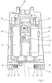
- Fig. 1 shows a rear view of the installation situation in the area of a carrier (1).
- the carrier (1) holds essentially with respect to their longitudinal axes vertically arranged filter elements (2), which at a Restrain gas flow through nitrogen.
- a filter element (2) to provide a substantially cylindrical housing shape and the air to be separated via valves (3) in one Feed the head area of the filter elements (2).
- the filter elements (2) can be designed such that a granular material is arranged inside to which nitrogen flows during a flow accumulates and lets the oxygen pass. Materials based on zeolites are particularly suitable.
- the carrier (1) has to hold the filter elements (2) and the collecting container (5) trough-shaped depressions on. Clamping the filter elements (2) in the trough-shaped depressions can over clamping tongues (6).
- the carrier (1) extends with a base substantially vertical so that the supported components used in the horizontal direction and can be removed.
- the carrier (1) opens into a bottom area Base plate (7), which is preferably in one piece with the Carrier (1) is formed.
- the base plate (7) has in recesses (8) arranged wheels (9) by pivotable wheel frames (10) are supported.
- Ventilation ducts (11) for cooling air in the area of their Transition to an environment with a labyrinthine Outflow structure provided for noise reduction are.
- a pressure reducer is located above the collecting container (5) (13) arranged, further from the carrier (1) Fan (14) for generating a required Cooling air flow through the ventilation ducts (11) supported.
- valves (3) preferably as three-two-way valves are formed, are on the inlet side via piping to a fine filter and an upstream one Coarse filter for the retention of air pollution connected.
- valves (3) for example also 5-3-way valves or valves with Middle position can be used. Show on the exit side the valves (3) connect to silencers.
- a compressor (18) is arranged within a delimited compressor room (17) within a delimited compressor room (17).
- the compressor room extends above the base plate (7).
- the compressor stands up without separate attachment Bearing blocks (19) and is also by positive locking fixed.
- Cooling elements (23) are surrounded by cooling air that flows through the ventilation ducts (11) can escape into the environment.
- the provided by the filter elements (2) and with Oxygenated air is in separate air lines guided separately from the cooling air.
- the carrier (1), the cover shell (21), the back part (20) and a cover element, not shown, for the compressor room (17) are held together by straps, which have quick fasteners and in Wells (24) are performed. This can result in a very quick assembly and disassembly are supported.
- the carrier (1), the back part (20) the cover shell (21) and the sealing shell for the compressor room (17) have a step-shaped contour, to self-alignment after assembly perform. This creates an exactly defined one and reproducible installation situation provided.
- the handle (16) has a screw connection (25) is connected to the bracket (15).
- the connection is made after the housing has been put on (26) on the carrier (1) and the cover elements. This connection thus fixes the Housing (26) caused relative to the carrier (1).
- a recessed grip (27) arranged to carry and handle the device support.
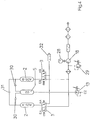
- Fig. 4 shows the essential pneumatic structure.
- the compressor (18) is driven by a motor (28) and compresses the one coarse filter and one Ambient air supplied through a fine filter.
- the exit of the Compressor (18) is equipped with a pressure relief valve (29) connected and supplies the filter elements via the valves (3) (2).
- the filter elements (2) are via check valves (30) connected to the collection container (5).
- An exit of the collecting container (5) is connected to the pressure reducer (13).
- One of the valves (3) provides a connection the compressor (18) free and the flushing filter element (2) assigned valve (3) makes a connection with the exhaust silencer (32).
- a further sound insulation can be done in that the ambient air supplied to the compressor (18) two hoses offset in the intake duct flows through. Sound absorption in the area of the blow-off air can, for example, with open-cell foam or felt are supported.
- the respective Material selection can be adapted to the present Noise spectrum take place.
- bearing blocks (19) of the compressor (18) As material for the bearing blocks (19) of the compressor (18) comes, for example, a closed cell Polyurethane in question. Prevent the bearing blocks (19) a direct transmission of the vibrations of the compressor (18) onto the foam material of the carrier (1) and the cover elements used.
- the inner contour of the Compressor room (17) is dimensioned by the used foamed elements chosen so that relative to the compressor (18) a maximum play of 5mm is present.
- a typical density for the foamed material of the Carrier (1) and the cover elements is 40 gr / l to 60 gr / l.
- As a material for these components for example expanded polypropylene, expanded Polyethylene or polystyrene can be used.
Abstract
Description
Die Erfindung betrifft einen Sauerstoffkonzentrator zur Verwendung im Bereich der medizinischen Beatmungstherapie, der mindestens einen von einem Gehäuse umgebenen Kompressor sowie mindestens ein vom Kompressor gespeistes und innerhalb des Gehäuses angeordnetes Filterelement aufweist, das Stickstoff zurückhält und für Sauerstoff durchlässig ist.The invention relates to an oxygen concentrator for Use in the field of medical ventilation therapy, the at least one of a housing surrounded compressor and at least one from Compressor powered and inside the case arranged filter element, the nitrogen holds back and is permeable to oxygen.
Derartige Sauerstoffkonzentratoren werden im Bereich der Medizintechnik verwendet, um Patienten mit Atemluft zu versorgen, die einen gegenüber der Umgebungsluft erhöhten Sauerstoffanteil aufweist. Im Hinblick auf zunehmend steigende Anforderungen an die Vereinfachung von Montage- und Demontagevorgängen sowie bezüglich von Verbesserungen der Schall- und Vibrationsdämpfung können die bislang bekannten Geräte nicht mehr alle an sie gestellten Anforderungen erfüllen.Such oxygen concentrators are in the range of medical technology used to breath patients to supply one to the ambient air has increased oxygen content. With regard increasing demands for simplification of assembly and disassembly processes as well as regarding Improvements in sound and vibration damping can not all of the devices known so far they meet the requirements.
Ähnliche Anforderungen im Bereich der Herstellung von Geräten der Datenverarbeitung konnten gemäß der EP-PS 0 546 211 dadurch erfüllt werden, daß ein Computerchassis aus einem Schaumstoff hergestellt wurde, in dem die verwendeten elektronischen Komponenten durch Formschluß gehalten werden. Eine unmittelbare Anwendung dieses Lösungsansatzes im Bereich der Medizintechnik erweist sich jedoch nicht als ausreichend.Similar requirements in the field of manufacturing Devices of data processing could according to EP-PS 0 546 211 are met by having a computer chassis was made from a foam in which the used electronic components by positive locking being held. An immediate application of this Approach in the field of medical technology proves however, is not sufficient.
Aus der US 46 67 669 ist bereits ein Sauerstoffkonzentrator bekannt, der eine Mehrzahl von Bauteilen aufweist und bei dem über eine vorgesehene Steuerung Einatmungsphasen sowie Ausatmungsphasen beeinflußt werden.From US 46 67 669 is already an oxygen concentrator known of a plurality of components has and in the provided control Inhalation phases and exhalation phases influenced will.
In der DE-OS 22 44 887 wird eine Atemmaske beschrieben, bei der ein schaumartiges Material verwendet wird, um eine Konturanpassung an das Gesicht des Patienten vorzunehmen. Durch die Konturanpassung kann eine hohe Abdichtwirkung erreicht werden.A breathing mask is described in DE-OS 22 44 887, where a foam-like material is used to a contour adjustment to the patient's face to make. A high Sealing effect can be achieved.
Aus der US 48 25 863 ist es bekannt, ein Beatmungsgerät derart zu konstruieren, daß ein Gehäuse aus zwei konzentrischen Gehäuseteilen ausgebildet ist. Die Gehäusehälften sind von einem geschäumten Material miteinander verbunden, ohne daß dieses Material jedoch Bauteile innerhalb des Gehäuses haltert.From US 48 25 863 it is known a respirator to be constructed in such a way that a housing of two concentric Housing parts is formed. The housing halves are made of a foamed material together connected without this material, however, components holds within the housing.
Die DE 100 95 40 344 A1 beschreibt ein Beatmungsgerät, das einen speziellen Überdruckverlauf bei der Patientenatmung generiert. Während der Überdruckphasen kann der Patient eine erhöhte Sauerstoffmenge aufnehmen. Der Druckverlauf wird durch ein geeignet ansteuerbares Gebläse erzeugt, das von einem Motor angetrieben ist.DE 100 95 40 344 A1 describes a respirator, which has a special overpressure curve at Patient breathing generated. During the overpressure phases the patient can absorb an increased amount of oxygen. The pressure curve is indicated by a controllable blower that is driven by a motor is.
Aufgabe der vorliegenden Erfindung ist es, einen Sauerstoffkonzentrator der einleitend genannten Art derart auszubilden, daß verbesserte Eigenschaften bei der Produktion und der späteren Nutzung bereitgestellt werden.The object of the present invention is a Oxygen concentrator of the type mentioned in the introduction train such that improved properties of production and later use will.
Diese Aufgabe wird erfindungsgemäß dadurch gelöst, daß mindestens einige der innerhalb des Gehäuses angeordneten Baugruppen von einem geschäumten Träger gehaltert sind, daß zusätzlich mindestens zwei weitere geschäumte Abdeckelemente gegen den Träger zur Umschließung der Bauelemente grenzen, daß innerhalb des Gehäuses ein separater Kompressorraum für den Kompressor angeordnet ist und daß der Kompressor lose auf Lagerblöcken innerhalb des Kompressorraumes aufgestellt ist.This object is achieved in that at least some of those located within the housing Assemblies held by a foamed carrier are that in addition at least two more are foamed Cover elements against the carrier to enclose the Components delimit that within the housing separate compressor room arranged for the compressor and that the compressor is loose on bearing blocks inside of the compressor room is set up.
Durch die Verwendung des Trägers aus einem geschäumten Material wird es auch im medizintechnischen Bereich ermöglicht, Bauelemente lediglich durch Formschluß zu haltern. Aufgrund der speziellen medizintechnischen Anforderungen sowie der konstruktiven Besonderheiten von Sauerstoffkonzentratoren wurde jedoch festgestellt, daß zur Abdeckung und zuverlässigen Halterung der Bauelemente mindestens zwei weitere geschäumte Abdeckelemente erforderlich sind, die gegen den Träger grenzen. Der Träger kann hierdurch im Bereich von zwei aneinander abgewandter Montageflächen mit Bauelementen bestückt werden, so daß mindestens zwei voneinander trennbare Montagebereiche bereitgestellt werden.By using the carrier from a foamed It also becomes material in the medical technology field allows components only by positive locking keep. Because of the special medical technology Requirements as well as the special design features of oxygen concentrators, however, has been found that to cover and reliably hold the components at least two other foamed cover elements are required that limit against the carrier. As a result, the carrier can adjoin one another in the region of two facing mounting surfaces with components be equipped so that at least two of each other separable assembly areas are provided.
Eine besonders gute Schall- und Vibrationsdämmung wird dadurch hervorgerufen, daß innerhalb des Gehäuses ein separater Kompressorraum für den Kompressor angeordnet ist.A particularly good sound and vibration insulation is caused by the fact that inside the housing separate compressor room arranged for the compressor is.
Zur Gewährleistung einer hohen Nutzluftqualität wird vorgeschlagen, daß getrennte Strömungswege für Kühlluft und Nutzluft angeordnet sind.To ensure a high level of useful air quality suggested that separate flow paths for cooling air and useful air are arranged.
Eine besonders gute Montage- und Servicefreundlichkeit kann dadurch hervorgerufen werden, daß der Träger mit drei separaten Abdeckelementen versehen ist. Particularly easy to install and service can be caused by the fact that the carrier with three separate cover elements is provided.
Zur Unterstützung eines gleichmäßigen Betriebes mit zyklischen Regenerationsphasen wird vorgeschlagen, daß der Träger zwei Filterelemente haltert.To support smooth operation with cyclical regeneration phases it is proposed that the carrier holds two filter elements.
Eine langfristige Betriebsfähigkeit kann dadurch unterstützt werden, daß innerhalb der Filterelemente Molekularfilter mit granulatartigem Filtermaterial zur Stickstoffanlagerung angeordnet sind. Insbesondere sind Granulate auf Basis von Zeolithen verwendbar.This can support long-term operability that molecular filters within the filter elements with granular filter material for nitrogen accumulation are arranged. In particular are Granules based on zeolites can be used.
Zur Realisierung einer Ansteuerung wird vorgeschlagen, daß die Filterelemente von Ventilen angesteuert sind.To implement a control, it is proposed that that the filter elements are controlled by valves.
Eine Filterregeneration kann dadurch durchgeführt werden, daß zur Regeneration des Filtermaterials eine zeitweilige Rückströmung zur Stickstoffausspülung vorgesehen ist.A filter regeneration can thus be carried out be that for the regeneration of the filter material temporary backflow provided for nitrogen flushing is.
Zur Bereitstellung einer ausreichenden Versorgungssicherheit mit gleichbleibendem Druckniveau wird vorgeschlagen, daß die Filterelemente mit einem Sammelbehälter verbunden sind.To provide adequate security of supply with constant pressure level, it is proposed that the filter elements with a collection container are connected.
Eine einfache Montage und Demontage wird dadurch unterstützt, daß der Träger und die Abdeckelemente von mindestens einem Riemen miteinander verspannt sind.A simple assembly and disassembly is supported that the carrier and the cover elements of at least one belt is tensioned together.
Eine weitere Reduktion von mechanischen Verbindungsteilen kann dadurch erfolgen, daß das Gehäuse über einen Handgriff mit dem Träger verbunden ist.A further reduction in mechanical connecting parts can be done in that the housing over a handle is connected to the carrier.
Ein sehr effektiver Ablauf des Regenerationsvorganges im Filterbereich wird dadurch unterstützt, daß die Ventile mit einer Steuerung zur Vorgabe einer mindestens zeitweilig gleichzeitigen Öffnung zur Durchführung der Rückspülung verbunden sind.A very effective process of the regeneration process in the filter area is supported by the fact that Valves with a control for specifying a at least temporarily simultaneous opening for implementation the backwash are connected.
Die Vibrationsdämpfung kann auch dadurch unterstützt werden, daß der Kompressor lose auf Lagerblöcken innerhalb des Kompressorraumes aufgestellt ist.The vibration damping can also be supported be that the compressor is loose on bearing blocks inside of the compressor room is set up.
Eine weitere Verbesserung der Montagefreundlichkeit erfolgt dadurch, daß der Träger im wesentlichen lotrecht angeordnete Montageflächen aufweist, in die die zu halternden Bauelemente in horizontaler Richtung einsetzbar sind.Another improvement in ease of installation takes place in that the carrier is essentially perpendicular has arranged mounting surfaces into which the components to be used can be used in the horizontal direction are.
Zur weiteren Optimierung der Geräuschdämmung wird vorgeschlagen, daß Lüftungskanäle zur Kühlluftableitung im Bereich eines Rückenteiles nach außen geführt sind.To further optimize noise insulation, it is proposed that ventilation ducts for cooling air discharge in Area of a back part are led outwards.
Eine zweckmäßige Strömungsführung besteht darin, daß mindestens einer der Luftkanäle unterhalb des Kompressors in einer Grundplatte verläuft.A convenient flow control is that at least one of the air channels below the compressor runs in a base plate.
Ebenfalls kann die Geräuschdämmung dadurch unterstützt werden, daß die Luftkanäle im Ausströmungsbereich in ein Ausgangslabyrinth zur Geräuschdämmung münden.This can also support noise insulation be that the air channels in the outflow area in an exit labyrinth for noise insulation.
Eine zweckmäßige Materialkombination zur Bereitstellung einer ausreichenden mechanischen Festigkeit sowie einer gleichzeitigen guten Geräusch- und Vibrationsdämpfung besteht darin, daß der Träger und die Abdeckelemente aus einem Schaumstoff mit einer Materialdichte im Bereich von 40 gr/l bis 60 gr/l bestehen.A convenient combination of materials to provide sufficient mechanical strength and one good noise and vibration dampening at the same time is that the carrier and the cover elements made of a foam with a material density in the area from 40 gr / l to 60 gr / l.
In der Zeichnung ist ein Ausführungsbeispiel der Erfindung schematisch dargestellt. Es zeigen:
- Fig. 1
- Eine rückwärtige Ansicht des Sauerstoffkonzentrators mit abgenommenem Gehäuse und abgenommener Rückenschale,
- Fig. 2
- eine perspektivische Vorderansicht des Sauerstoffkonzentrators gemäß Fig. 1 mit abgenommenem Gehäuse sowie abgenommener Vorderschale,
- Fig. 3
- einen stark vergrößerten Querschnitt im Bereich eines Überganges des Gehäuses in ein Griffteil und
- Fig. 4
- ein vereinfachtes pneumatisches Schaltbild der eingesetzten pneumatischen Komponenten.
- Fig. 1
- A rear view of the oxygen concentrator with the housing and back shell removed,
- Fig. 2
- 2 shows a perspective front view of the oxygen concentrator according to FIG. 1 with the housing removed and the front shell removed,
- Fig. 3
- a greatly enlarged cross section in the region of a transition of the housing into a handle part and
- Fig. 4
- a simplified pneumatic circuit diagram of the pneumatic components used.
Fig. 1 zeigt in einer rückwärtigen Ansicht die Einbausituation im Bereich eines Trägers (1). Der Träger (1) haltert bezüglich ihrer Längsachsen im wesentlichen vertikal angeordnete Filterelemente (2), die bei einer Gasdurchströmung Stickstoff zurückhalten. Beispielsweise ist es möglich, die Filterelemente (2) mit einer im wesentlichen zylindrischen Gehäuseform zu versehen und die zu trennende Luft über Ventile (3) in einem Kopfbereich der Filterelemente (2) zuzuführen. Abströmende und mit Sauerstoff angereicherte Luft wird über Verbindungsleitungen (4) in den Bereich eines Sammelbehälters (5) geleitet, der ebenfalls zylindrisch konstruiert sein kann.Fig. 1 shows a rear view of the installation situation in the area of a carrier (1). The carrier (1) holds essentially with respect to their longitudinal axes vertically arranged filter elements (2), which at a Restrain gas flow through nitrogen. For example it is possible to use a filter element (2) to provide a substantially cylindrical housing shape and the air to be separated via valves (3) in one Feed the head area of the filter elements (2). Outflow and becomes oxygen-enriched air via connecting lines (4) in the area of a Collected container (5), which is also cylindrical can be constructed.
Die Filterelemente (2) können derart ausgebildet sein, daß in ihrem Inneren ein granulatartiges Material angeordnet wird, an das sich Stickstoff bei einer Durchströmung anlagert und das Sauerstoff passieren läßt. Geeignet sind vor allem Materialien auf Basis von Zeolithen.The filter elements (2) can be designed such that a granular material is arranged inside to which nitrogen flows during a flow accumulates and lets the oxygen pass. Materials based on zeolites are particularly suitable.
Der Träger (1) weist zur Halterung der Filterelemente (2) und des Sammelbehälters (5) muldenförmige Vertiefungen auf. Ein Festklemmen der Filterelemente (2) in den muldenförmigen Vertiefungen kann über Klemmzungen (6) erfolgen. Der Träger (1) erstreckt sich mit einer Grundfläche im wesentlichen vertikal, so daß die gehalterten Bauelemente in horizontaler Richtung eingesetzt und entnommen werden können.The carrier (1) has to hold the filter elements (2) and the collecting container (5) trough-shaped depressions on. Clamping the filter elements (2) in the trough-shaped depressions can over clamping tongues (6). The carrier (1) extends with a base substantially vertical so that the supported components used in the horizontal direction and can be removed.
In einem Bodenbereich mündet der Träger (1) in eine Grundplatte (7) ein, die vorzugsweise einteilig mit dem Träger (1) ausgebildet ist. Die Grundplatte (7) weist in Vertiefungen (8) angeordnete Räder (9) auf, die von schwenkbaren Radgestellen (10) gehaltert sind.The carrier (1) opens into a bottom area Base plate (7), which is preferably in one piece with the Carrier (1) is formed. The base plate (7) has in recesses (8) arranged wheels (9) by pivotable wheel frames (10) are supported.
Durch die Grundplatte (7) hindurch erstrecken sich Lüftungskanäle (11) für Kühlluft, die im Bereich ihrer Überleitung in eine Umgebung mit einer labyrinthartigen Ausströmungsstruktur zur Geräuschminderung versehen sind.Extend through the base plate (7) Ventilation ducts (11) for cooling air in the area of their Transition to an environment with a labyrinthine Outflow structure provided for noise reduction are.
Oberhalb des Sammelbehälters (5) ist ein Druckminderer (13) angeordnet, desweiteren ist vom Träger (1) ein Ventilator (14) zur Erzeugung einer erforderlichen Kühlluftströmung durch die Lüftungskanäle (11) hindurch gehaltert.A pressure reducer is located above the collecting container (5) (13) arranged, further from the carrier (1) Fan (14) for generating a required Cooling air flow through the ventilation ducts (11) supported.
Die Ventile (3), die vorzugsweise als Drei-Zwei-Wegeventile ausgebildet sind, sind über Verrohrungen eingangsseitig an einen Feinfilter sowie einen vorgeschalteten Grobfilter zur Zurückhaltung von Luftverunreinigungen angeschlossen. Als Ventile (3) können beispielsweise ebenfalls 5-3-Wegeventile bzw. Ventile mit Mittelstellung verwendet werden. Ausgangsseitig weisen die Ventile (3) eine Verbindung zu Schalldämpfern auf.The valves (3), preferably as three-two-way valves are formed, are on the inlet side via piping to a fine filter and an upstream one Coarse filter for the retention of air pollution connected. As valves (3), for example also 5-3-way valves or valves with Middle position can be used. Show on the exit side the valves (3) connect to silencers.
Über eine geeignete Ansteuerung der Ventile (3) ist es möglich, eine abwechselnde Aktivierung der beiden Filterelemente (2) vorzunehmen. Nach einer Deaktivierung eines der Filterelemente (2) erfolgt in diesem Filterelement (2) ein partielles Rückströmen von Luft, so daß der im Filterelement (2) zurückgehaltene Stickstoff wieder ausgetragen und an die Umgebung abgegeben wird. Durch dieses Regenerationsprinzip wird nach Durchlaufen jeden alternierenden Arbeitszyklusses wieder der Ausgangszugestand bereitgestellt, so daß Wartungsarbeiten weitgehend entbehrlich sind. Insbesondere ist es nicht erforderlich, die Filterelemente (2) aufgrund zunehmender Stickstoffansammlung auszuwechseln.It is via a suitable control of the valves (3) possible alternating activation of the two Make filter elements (2). After a deactivation one of the filter elements (2) takes place in this Filter element (2) a partial backflow of air, so that the nitrogen retained in the filter element (2) carried out again and given to the environment becomes. Through this regeneration principle, after Go through every alternating work cycle the initial status is again provided so that Maintenance work is largely unnecessary. Especially it is not necessary to use the filter elements (2) to be replaced due to increasing nitrogen accumulation.
In lotrechter Richtung oben sind in den Träger (1) Haltebügel (15) eingebettet, die zur Befestigung eines in Fig. 3 dargestellten Handgriffes (16) dienen. Der Handgriff (16) wird nach einem Aufsetzen eines nicht dargestellten Gehäuses auf den Träger (1) montiert und verbindet nach einer entsprechenden Befestigung den Träger (1) mit dem äußeren Gehäuse.In the vertical direction above are in the carrier (1) Retaining bracket (15) embedded to secure a serve handle (16) shown in Fig. 3. Of the Handle (16) is not after putting on one shown housing mounted on the carrier (1) and connects the after a corresponding attachment Carrier (1) with the outer housing.
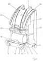
Aus der perspektivischen Darstellung in Fig. 2 ist erkennbar, daß innerhalb eines abgegrenzten Kompressorraumes (17) ein Kompressor (18) angeordnet ist. Der Kompressorraum erstreckt sich oberhalb der Grundplatte (7). Der Kompressor steht ohne separate Befestigung auf Lagerblöcken (19) und wird ebenfalls durch Formschluß fixiert.It can be seen from the perspective illustration in FIG. that within a delimited compressor room (17) a compressor (18) is arranged. Of the The compressor room extends above the base plate (7). The compressor stands up without separate attachment Bearing blocks (19) and is also by positive locking fixed.
Aus der Darstellung ist ebenfalls erkennbar, daß im rückwärtigen Teil der Träger (1) mit den gehalterten Bauelementen von einem Rückenteil (20) abgedeckt ist. Oberhalb des Kompressors (18) erstreckt sich eine vom Träger (1) abnehmbare Abdeckschale (21), die ein Bedienfeld (22) trägt.From the illustration it can also be seen that in rear part of the carrier (1) with the held Components is covered by a back part (20). Above the compressor (18) extends from Carrier (1) removable cover (21), which is a control panel (22) carries.
Durch die Anordnung des Kompressors (18) in einem separaten Kompressorraum (17) und die Lagerung auf den Lagerblöcken (19) wird eine sehr gute Schall- und Vibrationsentkopplung bereitgestellt. Kühlelemente (23) werden von Kühlluft umströmt, die durch die Lüftungskanäle (11) hindurch in die Umgebung entweichen kann. Die von den Filterelementen (2) bereitgestellte und mit Sauerstoff angereicherte Luft wird in separaten Luftleitungen getrennt von der Kühlluft geführt.By arranging the compressor (18) in a separate one Compressor room (17) and storage on the Bearing blocks (19) is a very good sound and Vibration decoupling provided. Cooling elements (23) are surrounded by cooling air that flows through the ventilation ducts (11) can escape into the environment. The provided by the filter elements (2) and with Oxygenated air is in separate air lines guided separately from the cooling air.
Der Träger (1), die Abdeckschale (21), das Rückenteil (20) sowie ein nicht dargestelltes Abdeckelement für den Kompressorraum (17) werden von Gurten zusammengehalten, die mit Schnellverschlüssen versehen und in Vertiefungen (24) geführt sind. Es kann hierdurch eine sehr schnelle Montage und Demontage unterstützt werden.The carrier (1), the cover shell (21), the back part (20) and a cover element, not shown, for the compressor room (17) are held together by straps, which have quick fasteners and in Wells (24) are performed. This can result in a very quick assembly and disassembly are supported.
Aus der Darstellung in Fig. 2 ist ebenfalls erkennbar, daß der Träger (1), das Rückenteil (20) die Abdeckschale (21) sowie die Verschlußschale für den Kompressorraum (17) eine stufenförmige Kontur aufweisen, um nach einem Zusammenfügen eine Selbstausrichtung durchzuführen. Es wird hierdurch eine exakt definierte und reproduzierbare Einbausituation bereitgestellt. It can also be seen from the illustration in FIG. that the carrier (1), the back part (20) the cover shell (21) and the sealing shell for the compressor room (17) have a step-shaped contour, to self-alignment after assembly perform. This creates an exactly defined one and reproducible installation situation provided.
Aus der vergrößerten Querschnittdarstellung in Fig. 3 ist erkennbar, daß der Handgriff (16) über eine Verschraubung (25) mit dem Haltebügel (15) verbunden ist. Die Verbindung erfolgt nach einem Aufsetzen des Gehäuses (26) auf den Träger (1) und die Abdeckelemente. Durch diese Verbindung wird somit eine Fixierung des Gehäuses (26) relativ zum Träger (1) hervorgerufen. Unterhalb des Handgriffes (16) ist eine Griffmulde (27) angeordnet, um ein Tragen und Handhaben des Gerätes zu unterstützen.From the enlarged cross-sectional view in FIG. 3 it can be seen that the handle (16) has a screw connection (25) is connected to the bracket (15). The connection is made after the housing has been put on (26) on the carrier (1) and the cover elements. This connection thus fixes the Housing (26) caused relative to the carrier (1). Below the handle (16) is a recessed grip (27) arranged to carry and handle the device support.
Fig. 4 zeigt den wesentlichen pneumatischen Aufbau. Der Kompressor (18) wird von einem Motor (28) angetrieben und verdichtet die zuvor einem Grobfilter und einem Feinfilter zugeleitete Umgebungsluft. Der Ausgang des Kompressors (18) ist mit einem Überdruckventil (29) verbunden und versorgt über die Ventile (3) die Filterelemente (2). Die Filterelemente (2) sind über Rückschlagventile (30) an den Sammelbehälter (5) angeschlossen. Zusätzlich ist eine Überbrückung mit einer Spüldüse (31) vorgesehen. Ein Ausgang des Sammelbehälters (5) ist an den Druckminderer (13) angeschlossen. Bei einer Rückspülung der Filterelemente (2) zum Entfernen des angelagerten Stickstoffes nach entsprechender Freischaltung der Ventile (3) erfolgt eine Schalldämpfung der abströmenden Luft über einen Abgasschalldämpfer (32).Fig. 4 shows the essential pneumatic structure. Of the The compressor (18) is driven by a motor (28) and compresses the one coarse filter and one Ambient air supplied through a fine filter. The exit of the Compressor (18) is equipped with a pressure relief valve (29) connected and supplies the filter elements via the valves (3) (2). The filter elements (2) are via check valves (30) connected to the collection container (5). In addition, there is a bypass Flushing nozzle (31) provided. An exit of the collecting container (5) is connected to the pressure reducer (13). When the filter elements (2) are backwashed to remove the accumulated nitrogen after appropriate The valves (3) are activated Sound attenuation of the outgoing air via an exhaust silencer (32).
Bei einer Durchführung der Rückspülung für die Stickstoffentfernung erfolgt eine gleichzeitige Öffnung der Ventile (3) zur Kopplung über die Spüldüse (31) für etwa eine Sekunde. Dieser Zeitraum ist in der Regel für eine Regeneration des Filtermaterials ausreichend. When performing the backwash for nitrogen removal there is a simultaneous opening of the Valves (3) for coupling via the flushing nozzle (31) for about a second. This period is usually for regeneration of the filter material is sufficient.
Eines der Ventile (3) gibt hierbei eine Verbindung mit dem Kompressor (18) frei und das dem spülenden Filterelement (2) zugeordnete Ventil (3) führt eine Verbindung mit dem Abgasschalldämpfer (32) durch.One of the valves (3) provides a connection the compressor (18) free and the flushing filter element (2) assigned valve (3) makes a connection with the exhaust silencer (32).
Eine weitere Schalldämmung kann dadurch erfolgen, daß die dem Kompressor (18) zugeführte Umgebungsluft durch zwei versetzt in den Ansaugkanal eingebrachte Schläuche hindurchströmt. Eine Schalldämpfung im Bereich der Abblasluft kann beispielsweise mit offenzelligem Schaumstoff oder Filz unterstützt werden. Die jeweilige Materialauswahl kann in Anpassung an das vorliegende Geräuschspektrum erfolgen.A further sound insulation can be done in that the ambient air supplied to the compressor (18) two hoses offset in the intake duct flows through. Sound absorption in the area of the blow-off air can, for example, with open-cell foam or felt are supported. The respective Material selection can be adapted to the present Noise spectrum take place.
Als Material für die Lagerblöcke (19) des Kompressors (18) kommt beispielsweise ein geschlossenzelliges Polyurethan in Frage. Die Lagerblöcke (19) verhindern eine direkte Übertragung der Vibrationen des Kompressors (18) auf das Schaummaterial des Trägers (1) und der verwendeten Abdeckelemente. Die Innenkontur des Kompressorraumes (17) ist durch die Dimensionierung der eingesetzten geschäumten Elemente so gewählt, daß relativ zum Kompressor (18) ein maximales Spiel von 5mm vorliegt. Hierdurch werden Relativbewegungen zwischen den Bauteilen kontrolliert und Beschädigungen bei einem Einwirken von Beschleunigungen vermieden.As material for the bearing blocks (19) of the compressor (18) comes, for example, a closed cell Polyurethane in question. Prevent the bearing blocks (19) a direct transmission of the vibrations of the compressor (18) onto the foam material of the carrier (1) and the cover elements used. The inner contour of the Compressor room (17) is dimensioned by the used foamed elements chosen so that relative to the compressor (18) a maximum play of 5mm is present. As a result, relative movements between the components checked and damage to one Avoidance of accelerations.
Eine typische Dichte für das geschäumte Material des Trägers (1) und der Abdeckelemente beträgt 40 gr/l bis 60 gr/l. Als Material für diese Bauteile kann beispielsweise expandiertes Polypropylen, expandiertes Polyethylen oder Polystyrol verwendet werden.A typical density for the foamed material of the Carrier (1) and the cover elements is 40 gr / l to 60 gr / l. As a material for these components, for example expanded polypropylene, expanded Polyethylene or polystyrene can be used.
Claims (16)
Applications Claiming Priority (2)
| Application Number | Priority Date | Filing Date | Title |
|---|---|---|---|
| DE19725632A DE19725632C1 (en) | 1997-06-17 | 1997-06-17 | Oxygen@ concentrator for breathing therapy |
| DE19725632 | 1997-06-17 |
Publications (3)
| Publication Number | Publication Date |
|---|---|
| EP0885645A2 true EP0885645A2 (en) | 1998-12-23 |
| EP0885645A3 EP0885645A3 (en) | 1999-03-24 |
| EP0885645B1 EP0885645B1 (en) | 2005-01-05 |
Family
ID=7832761
Family Applications (1)
| Application Number | Title | Priority Date | Filing Date |
|---|---|---|---|
| EP98106126A Expired - Lifetime EP0885645B1 (en) | 1997-06-17 | 1998-04-03 | Oxygen concentrator |
Country Status (2)
| Country | Link |
|---|---|
| EP (1) | EP0885645B1 (en) |
| DE (2) | DE19725632C1 (en) |
Cited By (4)
| Publication number | Priority date | Publication date | Assignee | Title |
|---|---|---|---|---|
| DE19938134A1 (en) * | 1999-08-16 | 2001-08-23 | Map Gmbh | Ventilator arrangement to assist patient breathing over long periods has additional sound sources within the housing that act to cancel out sounds produced by the ventilator, etc., resulting in a quieter device |
| CN111939405A (en) * | 2020-08-13 | 2020-11-17 | 安徽康居人健康科技有限公司 | Breathing and oxygen production all-in-one machine convenient to disassemble |
| US11915570B2 (en) | 2020-07-16 | 2024-02-27 | Ventec Life Systems, Inc. | System and method for concentrating gas |
| US11931689B2 (en) | 2020-07-16 | 2024-03-19 | Ventec Life Systems, Inc. | System and method for concentrating gas |
Families Citing this family (2)
| Publication number | Priority date | Publication date | Assignee | Title |
|---|---|---|---|---|
| DE10204467A1 (en) * | 2002-02-05 | 2003-08-14 | Weinmann G Geraete Med | Method and device for providing breathing gas |
| DE102007014613A1 (en) * | 2006-04-01 | 2007-11-22 | Weinmann Geräte für Medizin GmbH + Co. KG | Artificial respiration device, has source of inhaled gas with patient interface attached over feeder line, which is provided with breathing element and silencer arranged in range of breathing element |
Citations (4)
| Publication number | Priority date | Publication date | Assignee | Title |
|---|---|---|---|---|
| DE2244887A1 (en) | 1972-07-24 | 1974-02-07 | Carl Gmaehle | RESPIRATORY MASK |
| US4667669A (en) | 1983-12-09 | 1987-05-26 | Dr/a/ gerwerk AG | Cycle respirator for pressure operation |
| US4825863A (en) | 1984-05-22 | 1989-05-02 | Centre National De La Recherche Scientifique (C.N.R.S.) | Portable hot, humid air inhalator for combatting hypothermia in humans |
| DE19540344A1 (en) | 1994-10-27 | 1997-03-06 | Innovative Medical Systems Inc | Respirator |
Family Cites Families (7)
| Publication number | Priority date | Publication date | Assignee | Title |
|---|---|---|---|---|
| US4342573A (en) * | 1979-10-12 | 1982-08-03 | Greene & Kellogg, Incorporated | Compact oxygen concentrator |
| US4378982A (en) * | 1981-08-28 | 1983-04-05 | Greene & Kellogg, Inc. | Compact oxygen concentrator |
| US4511377A (en) * | 1983-11-01 | 1985-04-16 | Greene & Kellogg, Inc. | Apparatus for the production of oxygen |
| US4826510A (en) * | 1988-01-13 | 1989-05-02 | The John Bunn Company | Portable low profile DC oxygen concentrator |
| US5112367A (en) * | 1989-11-20 | 1992-05-12 | Hill Charles C | Fluid fractionator |
| JPH07275632A (en) * | 1994-04-13 | 1995-10-24 | Teijin Ltd | Oxygen concentrating apparatus |
| JP3577763B2 (en) * | 1995-01-09 | 2004-10-13 | 藤沢薬品工業株式会社 | Pressure fluctuation adsorption type oxygen concentrator |
-
1997
- 1997-06-17 DE DE19725632A patent/DE19725632C1/en not_active Expired - Fee Related
-
1998
- 1998-04-03 DE DE59812463T patent/DE59812463D1/en not_active Expired - Fee Related
- 1998-04-03 EP EP98106126A patent/EP0885645B1/en not_active Expired - Lifetime
Patent Citations (4)
| Publication number | Priority date | Publication date | Assignee | Title |
|---|---|---|---|---|
| DE2244887A1 (en) | 1972-07-24 | 1974-02-07 | Carl Gmaehle | RESPIRATORY MASK |
| US4667669A (en) | 1983-12-09 | 1987-05-26 | Dr/a/ gerwerk AG | Cycle respirator for pressure operation |
| US4825863A (en) | 1984-05-22 | 1989-05-02 | Centre National De La Recherche Scientifique (C.N.R.S.) | Portable hot, humid air inhalator for combatting hypothermia in humans |
| DE19540344A1 (en) | 1994-10-27 | 1997-03-06 | Innovative Medical Systems Inc | Respirator |
Cited By (6)
| Publication number | Priority date | Publication date | Assignee | Title |
|---|---|---|---|---|
| DE19938134A1 (en) * | 1999-08-16 | 2001-08-23 | Map Gmbh | Ventilator arrangement to assist patient breathing over long periods has additional sound sources within the housing that act to cancel out sounds produced by the ventilator, etc., resulting in a quieter device |
| DE19938134C2 (en) * | 1999-08-16 | 2002-01-17 | Map Gmbh | Device for supplying a breathing gas under positive pressure |
| US11915570B2 (en) | 2020-07-16 | 2024-02-27 | Ventec Life Systems, Inc. | System and method for concentrating gas |
| US11931689B2 (en) | 2020-07-16 | 2024-03-19 | Ventec Life Systems, Inc. | System and method for concentrating gas |
| CN111939405A (en) * | 2020-08-13 | 2020-11-17 | 安徽康居人健康科技有限公司 | Breathing and oxygen production all-in-one machine convenient to disassemble |
| CN111939405B (en) * | 2020-08-13 | 2023-02-21 | 安徽康居人健康科技有限公司 | Breathing and oxygen production all-in-one machine convenient to disassemble |
Also Published As
| Publication number | Publication date |
|---|---|
| DE59812463D1 (en) | 2005-02-10 |
| DE19725632C1 (en) | 1998-10-01 |
| EP0885645A3 (en) | 1999-03-24 |
| EP0885645B1 (en) | 2005-01-05 |
Similar Documents
| Publication | Publication Date | Title |
|---|---|---|
| DE60312837T2 (en) | OXYGEN CONCENTRATOR WITH REDUCED NOISE LEVEL | |
| DE60032649T2 (en) | Air treatment system | |
| DE69729364T2 (en) | Process and apparatus for purifying gases by pressure swing adsorption | |
| DE69907754T2 (en) | FILTER CARRIER, FILTER CARRIER ARRANGEMENT AND SYSTEM | |
| EP1859837B1 (en) | Protective clothing for ABC-protection with improved air exchange function | |
| DE10315607B4 (en) | Ventilation system for protective clothing | |
| EP0872643B1 (en) | Air inlet for a fan | |
| DE19903732A1 (en) | Ventilation device and method for processing a respiratory gas | |
| DE19725632C1 (en) | Oxygen@ concentrator for breathing therapy | |
| DE3405237A1 (en) | BREATHING DEVICE | |
| WO2006131161A1 (en) | Air conduction duct and device for ventilating, heating and/or air conditioning a vehicle interior | |
| DE2908085A1 (en) | Air supply filter for the interior of motor vehicles - uses several layers of chemical sorption agents and has low mfg. cost | |
| DE3817084C1 (en) | Odour-binding filter in the feed air stream of a motor vehicle interior | |
| DE60020525T2 (en) | METHOD FOR PRODUCING A VENTILATION DEVICE AND VENTILATION DEVICE | |
| EP0606538A1 (en) | Suction removal of stone dust | |
| EP0259674A2 (en) | Process and device for the purification of air charged with toxic gases | |
| DE3815907A1 (en) | FILTER FOR FILTERING THE AIR INTRODUCED INTO THE INTERIOR OF A MOTOR VEHICLE | |
| DE60305456T2 (en) | Air purification system for vehicles with an oxygen-supplying function | |
| AT525935B1 (en) | Compressor for an air suspension | |
| DE10304110B4 (en) | Hard hat, especially full face helmet | |
| DE102020116991B3 (en) | Breathing air filter and method for operating a breathing air filter | |
| EP4212214A1 (en) | Filter unit comprising a filter block, a damping layer and a housing and method for producing such a filter unit | |
| DE3149425C2 (en) | Respiratory protection filter | |
| DE19645941C1 (en) | Gas-conduit component | |
| DE202022103238U1 (en) | Suction system for a beehive |
Legal Events
| Date | Code | Title | Description |
|---|---|---|---|
| PUAI | Public reference made under article 153(3) epc to a published international application that has entered the european phase |
Free format text: ORIGINAL CODE: 0009012 |
|
| AK | Designated contracting states |
Kind code of ref document: A2 Designated state(s): BE DE FR NL SE |
|
| AX | Request for extension of the european patent |
Free format text: AL;LT;LV;MK;RO;SI |
|
| PUAL | Search report despatched |
Free format text: ORIGINAL CODE: 0009013 |
|
| AK | Designated contracting states |
Kind code of ref document: A3 Designated state(s): AT BE CH CY DE DK ES FI FR GB GR IE IT LI LU MC NL PT SE |
|
| AX | Request for extension of the european patent |
Free format text: AL;LT;LV;MK;RO;SI |
|
| 17P | Request for examination filed |
Effective date: 19990319 |
|
| AKX | Designation fees paid |
Free format text: BE DE FR NL SE |
|
| 17Q | First examination report despatched |
Effective date: 20030228 |
|
| GRAP | Despatch of communication of intention to grant a patent |
Free format text: ORIGINAL CODE: EPIDOSNIGR1 |
|
| GRAS | Grant fee paid |
Free format text: ORIGINAL CODE: EPIDOSNIGR3 |
|
| GRAA | (expected) grant |
Free format text: ORIGINAL CODE: 0009210 |
|
| AK | Designated contracting states |
Kind code of ref document: B1 Designated state(s): BE DE FR NL SE |
|
| PG25 | Lapsed in a contracting state [announced via postgrant information from national office to epo] |
Ref country code: NL Free format text: LAPSE BECAUSE OF FAILURE TO SUBMIT A TRANSLATION OF THE DESCRIPTION OR TO PAY THE FEE WITHIN THE PRESCRIBED TIME-LIMIT Effective date: 20050105 |
|
| RAP2 | Party data changed (patent owner data changed or rights of a patent transferred) |
Owner name: WEINMANN GERAETE FUER MEDIZIN GMBH & CO. KG |
|
| REF | Corresponds to: |
Ref document number: 59812463 Country of ref document: DE Date of ref document: 20050210 Kind code of ref document: P |
|
| NLT2 | Nl: modifications (of names), taken from the european patent patent bulletin |
Owner name: WEINMANN GERAETE FUER MEDIZIN GMBH & CO. KG |
|
| PG25 | Lapsed in a contracting state [announced via postgrant information from national office to epo] |
Ref country code: SE Free format text: LAPSE BECAUSE OF FAILURE TO SUBMIT A TRANSLATION OF THE DESCRIPTION OR TO PAY THE FEE WITHIN THE PRESCRIBED TIME-LIMIT Effective date: 20050405 |
|
| PG25 | Lapsed in a contracting state [announced via postgrant information from national office to epo] |
Ref country code: BE Free format text: LAPSE BECAUSE OF NON-PAYMENT OF DUE FEES Effective date: 20050430 |
|
| NLV1 | Nl: lapsed or annulled due to failure to fulfill the requirements of art. 29p and 29m of the patents act | ||
| BERE | Be: lapsed |
Owner name: GOTTLIEB WEINMANN GERATE FUR MEDIZIN UND ARBEITSSC Effective date: 20050430 |
|
| PLBE | No opposition filed within time limit |
Free format text: ORIGINAL CODE: 0009261 |
|
| STAA | Information on the status of an ep patent application or granted ep patent |
Free format text: STATUS: NO OPPOSITION FILED WITHIN TIME LIMIT |
|
| ET | Fr: translation filed | ||
| 26N | No opposition filed |
Effective date: 20051006 |
|
| BERE | Be: lapsed |
Owner name: GOTTLIEB WEINMANN GERATE FUR MEDIZIN UND ARBEITSSC Effective date: 20050430 |
|
| PGFP | Annual fee paid to national office [announced via postgrant information from national office to epo] |
Ref country code: DE Payment date: 20080218 Year of fee payment: 11 |
|
| REG | Reference to a national code |
Ref country code: FR Ref legal event code: ST Effective date: 20091231 |
|
| PG25 | Lapsed in a contracting state [announced via postgrant information from national office to epo] |
Ref country code: DE Free format text: LAPSE BECAUSE OF NON-PAYMENT OF DUE FEES Effective date: 20091103 |
|
| PG25 | Lapsed in a contracting state [announced via postgrant information from national office to epo] |
Ref country code: FR Free format text: LAPSE BECAUSE OF NON-PAYMENT OF DUE FEES Effective date: 20091222 |
|
| PGFP | Annual fee paid to national office [announced via postgrant information from national office to epo] |
Ref country code: FR Payment date: 20080430 Year of fee payment: 11 |