EP0885596A1 - Monopolar electrosurgical trocar - Google Patents
Monopolar electrosurgical trocar Download PDFInfo
- Publication number
- EP0885596A1 EP0885596A1 EP98304805A EP98304805A EP0885596A1 EP 0885596 A1 EP0885596 A1 EP 0885596A1 EP 98304805 A EP98304805 A EP 98304805A EP 98304805 A EP98304805 A EP 98304805A EP 0885596 A1 EP0885596 A1 EP 0885596A1
- Authority
- EP
- European Patent Office
- Prior art keywords
- electrosurgical
- adapter
- trocar
- aperture
- monopolar
- Prior art date
- Legal status (The legal status is an assumption and is not a legal conclusion. Google has not performed a legal analysis and makes no representation as to the accuracy of the status listed.)
- Granted
Links
Images


Classifications
-
- A—HUMAN NECESSITIES
- A61—MEDICAL OR VETERINARY SCIENCE; HYGIENE
- A61B—DIAGNOSIS; SURGERY; IDENTIFICATION
- A61B17/00—Surgical instruments, devices or methods, e.g. tourniquets
- A61B17/34—Trocars; Puncturing needles
- A61B17/3417—Details of tips or shafts, e.g. grooves, expandable, bendable; Multiple coaxial sliding cannulas, e.g. for dilating
-
- A—HUMAN NECESSITIES
- A61—MEDICAL OR VETERINARY SCIENCE; HYGIENE
- A61B—DIAGNOSIS; SURGERY; IDENTIFICATION
- A61B17/00—Surgical instruments, devices or methods, e.g. tourniquets
- A61B17/34—Trocars; Puncturing needles
-
- A—HUMAN NECESSITIES
- A61—MEDICAL OR VETERINARY SCIENCE; HYGIENE
- A61B—DIAGNOSIS; SURGERY; IDENTIFICATION
- A61B18/00—Surgical instruments, devices or methods for transferring non-mechanical forms of energy to or from the body
- A61B18/04—Surgical instruments, devices or methods for transferring non-mechanical forms of energy to or from the body by heating
- A61B18/12—Surgical instruments, devices or methods for transferring non-mechanical forms of energy to or from the body by heating by passing a current through the tissue to be heated, e.g. high-frequency current
- A61B18/14—Probes or electrodes therefor
- A61B18/1487—Trocar-like, i.e. devices producing an enlarged transcutaneous opening
-
- A—HUMAN NECESSITIES
- A61—MEDICAL OR VETERINARY SCIENCE; HYGIENE
- A61B—DIAGNOSIS; SURGERY; IDENTIFICATION
- A61B17/00—Surgical instruments, devices or methods, e.g. tourniquets
- A61B17/34—Trocars; Puncturing needles
- A61B17/3476—Powered trocars, e.g. electrosurgical cutting, lasers, powered knives
-
- A—HUMAN NECESSITIES
- A61—MEDICAL OR VETERINARY SCIENCE; HYGIENE
- A61B—DIAGNOSIS; SURGERY; IDENTIFICATION
- A61B18/00—Surgical instruments, devices or methods for transferring non-mechanical forms of energy to or from the body
- A61B18/04—Surgical instruments, devices or methods for transferring non-mechanical forms of energy to or from the body by heating
- A61B18/12—Surgical instruments, devices or methods for transferring non-mechanical forms of energy to or from the body by heating by passing a current through the tissue to be heated, e.g. high-frequency current
- A61B18/14—Probes or electrodes therefor
- A61B18/1442—Probes having pivoting end effectors, e.g. forceps
-
- A—HUMAN NECESSITIES
- A61—MEDICAL OR VETERINARY SCIENCE; HYGIENE
- A61B—DIAGNOSIS; SURGERY; IDENTIFICATION
- A61B18/00—Surgical instruments, devices or methods for transferring non-mechanical forms of energy to or from the body
- A61B18/04—Surgical instruments, devices or methods for transferring non-mechanical forms of energy to or from the body by heating
- A61B18/12—Surgical instruments, devices or methods for transferring non-mechanical forms of energy to or from the body by heating by passing a current through the tissue to be heated, e.g. high-frequency current
- A61B18/14—Probes or electrodes therefor
- A61B18/1482—Probes or electrodes therefor having a long rigid shaft for accessing the inner body transcutaneously in minimal invasive surgery, e.g. laparoscopy
-
- A—HUMAN NECESSITIES
- A61—MEDICAL OR VETERINARY SCIENCE; HYGIENE
- A61B—DIAGNOSIS; SURGERY; IDENTIFICATION
- A61B18/00—Surgical instruments, devices or methods for transferring non-mechanical forms of energy to or from the body
- A61B2018/00053—Mechanical features of the instrument of device
- A61B2018/00172—Connectors and adapters therefor
- A61B2018/00178—Electrical connectors
-
- H—ELECTRICITY
- H01—ELECTRIC ELEMENTS
- H01R—ELECTRICALLY-CONDUCTIVE CONNECTIONS; STRUCTURAL ASSOCIATIONS OF A PLURALITY OF MUTUALLY-INSULATED ELECTRICAL CONNECTING ELEMENTS; COUPLING DEVICES; CURRENT COLLECTORS
- H01R2201/00—Connectors or connections adapted for particular applications
- H01R2201/12—Connectors or connections adapted for particular applications for medicine and surgery
-
- H—ELECTRICITY
- H01—ELECTRIC ELEMENTS
- H01R—ELECTRICALLY-CONDUCTIVE CONNECTIONS; STRUCTURAL ASSOCIATIONS OF A PLURALITY OF MUTUALLY-INSULATED ELECTRICAL CONNECTING ELEMENTS; COUPLING DEVICES; CURRENT COLLECTORS
- H01R35/00—Flexible or turnable line connectors, i.e. the rotation angle being limited
- H01R35/04—Turnable line connectors with limited rotation angle with frictional contact members
Definitions
- the present invention relates, in general, to an improved electrosurgical trocar adapted to provide electrosurgical energy to specially adapted cordless electrosurgical instruments used with the electrosurgical trocar and, more particularly, to a monopolar electrosurgical trocar and trocar adapter.
- the surgical trocar has become the mainstay in the development and acceptance of endoscopic surgical procedures. Endoscopic surgery involves the performance of surgery through a number of openings having a relatively small diameter. These openings are made with the trocar, which typically includes a trocar obturator and a trocar cannula.
- the obturator is the piercing implement which punctures the body wall to make the opening. Once the puncture is made, the obturator is withdrawn from the cannula. The cannula then provides a small diameter passageway into and through the body wall to provide access for additional surgical instrumentation to the surgical site.
- the function, structure and operation of a typical trocar is described in detail in U.S. Patent 5,387,197, which is hereby incorporated herein by reference.
- Such additional surgical instruments may include, for example, bipolar or monopolar electrosurgical instruments which utilize radio frequency electrosurgical energy.
- Known electrosurgical instruments include, for example, bipolar forceps, bipolar scissors, monopolar-hook, monopolar-scissors and, bipolar endocutters. Each of those instruments has an electrosurgical end effector which is adapted to treat tissue through the application of electrosurgical (e.g. radio frequency or RF) energy to tissue which is brought in contact with the electrosurgical end effector.
- electrosurgical e.g. radio frequency or RF
- Most known electrosurgical instruments are connected by electrical cords to electrosurgical generators.
- the structure and operation of a typical bipolar cutter/stapler ("bipolar endocutter") is described in U.S. Patent No. 5,403,312 which is hereby incorporated herein by reference.
- the structure and operation of typical monopolar electrosurgical instruments is described in US Patent No. 5,207,691 and US Patent 5,273,524 which are hereby incorporated herein by reference.
- Electrosurgical generators such as the Force II generator which is available from Valley Lab of Bolder Colorado, supply electrical energy to the electrosurgical instruments through electrical cords.
- the electrical cords being attached directly to the electrosurgical instrument, may make the electrosurgical instrument inconvenient to use. Alternatively, electrical cords may cause undesirable delays as one electrosurgical instrument is unplugged from the generator and another is plugged in.
- a cordless electrosurgical instrument would have to be connected to the electrosurgical generator through some alternate arrangement. Therefore, it would also be advantageous to design a trocar or a trocar adapter which is adapted to conduct electrosurgical energy to specially designed cordless electrosurgical instruments.
- a monopolar electrosurgical trocar or trocar adapter particularly adapted for use with monopolar electrosurgical instruments.
- a monopolar surgical trocar or trocar adapter is adapted to conduct electrosurgical energy to specially adapted cordless electrosurgical instruments.
- an electrosurgical trocar includes a cannula, an electrosurgical adapter and a locking connector adapted to connect the cannula to the electrosurgical adapter.
- the cannula is an elongated tube which may be inserted into a body cavity, duct or vessel.
- the electrosurgical adapter includes a housing with an elongated central aperture, at least one electrical contact positioned in and extending axially along the elongated aperture, at least one internal electrical conductor, at least one external conductor, an outer housing and an electrical cord.
- An electrosurgical trocar or trocar adapter according to the present invention may also include a compression mechanism.
- the adapter aperture is formed by an aperture wall positioned in the adapter housing.
- the electrical contact is positioned in and extends axially along the aperture, forming at least a portion of the walls of the aperture.
- the electrical contact may be divided into two pieces within the aperture.
- the internal electrical conductor connects the electrical contact to the external connector.
- the compression mechanism biases the pieces of the electrical contact toward the center of the adapter aperture.
- An electrical cord is connected to the external connector such that the electrical cord may be used to plug the adapter into one output of an electrosurgical generator.
- a return electrode may be affixed to the skin of the patient as in a conventional monopolar arrangement.
- the electrical contact is divided into a first stator plate and a second stator plate.
- the second stator plate is positioned opposite the first stator plate.
- the second stator plate is electrically connected to the first stator plate.
- the compression member includes one or more compression rings positioned around the first and second electrical contacts.
- the electrosurgical trocar includes a locking connector which connects the cannula to the adapter.
- the adapter includes first and second locking cleats extending from the distal end of the connector.
- the cannula includes receptors such as indentations or ribs which hold the distal ends of the locking cleats in place, thus holding the connector in contact with the cannula.
- Figure 1 is a perspective view of a monopolar electrosurgical trocar according to the present invention.
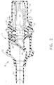
- Figure 2 is a plan view section taken through the electrosurgical trocar illustrated in Figure 1.
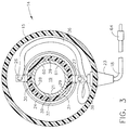
- Figure 3 is a section view taken along line 3-3 of Figure 2.
- Figure 4 is a perspective view of a cordless electrosurgical instrument according to the present invention.
- Figure 5 is an exploded perspective view of the distal end of the cordless electrosurgical instrument illustrated in Figure 4.
- FIG. 1 is a perspective view of a monopolar electrosurgical trocar according to the present invention.
- Electrosurgical trocar 11 includes trocar cannula 8 and electrosurgical adapter 14.
- Electrosurgical trocar 11 may also include an obturator assembly (not shown) such as the one illustrated in U.S. Patent 5,387,197, which has been previously incorporated herein by reference.
- Trocar cannula 8 includes cannula housing 12 and cannula tube 10, extending from housing 12.
- Electrosurgical adapter 14 includes an adapter housing 15, locking connector 17 and an electric cord 18.
- electrosurgical adapter 14 is connected to trocar cannula 8 by locking connector 17.
- Locking connector 17 includes locking cleat 20 and release button 22. It will be apparent that electrosurgical adapter 14 may be integrated directly into trocar cannula 8, thus eliminating the need for locking connector 17.
- FIG. 2 is a plain view section taken through electrosurgical trocar 11.
- cannula housing 12 includes flapper valve 34 and ring gasket 33.
- Electrosurgical adapter 14 includes central aperture 19, front flange 25 and base flange 24.
- Aperture 19 is an elongated aperture for receiving working instruments such as endoscopic electrosurgical instruments.
- Electrosurgical adapter 14 further includes one or more interior electrical contacts which, in the embodiment illustrated in Figures 2 and 3, comprise stator plates 28 and 29. At least a portion of the interior wall of central aperture 19 is formed by upper insulator 30 and upper stator plate 28.
- Upper insulator 30 is positioned against front flange 25 and base flange 24.
- Compression member 32 is, in the present embodiment, an o-ring which is positioned outside of upper insulator 30 to bias upper insulator 30 and upper stator plate 28 toward the center of central aperture 19.
- Compression member 32 may also be, for example, a spring, a flexible sleeve, a plurality of o-rings or any other suitable biasing member.
- FIG. 3 is a sectional view of electrosurgical adapter 14 taken along line 3-3 of Figure 2.
- Central aperture 19 is defined by aperture interior wall 21.
- the portion of interior wall 21 visible in Figure 3 is formed, at least in part, by upper contact surface 60 of upper stator plate 28 and lower contact surface 61 of lower stator plate 29.
- Upper stator plate 28 and lower stator plate 29 are positioned on, and may be electrically insulated from one another by, upper insulator 30 and lower insulator 31, respectively.
- upper stator plate 28 and lower stator plate 29 may be in electrical contact.
- stator plate 28 and stator plate 29 may be joined to form a single electrode, which single electrode may or may not include a compression gap 39.
- compression gap 39 In order to ensure that contact is maintained, compression gap 39 must be relatively small and, in particular, compression gap 39 should be smaller than the diameter of the contact electrode on any electrosurgical instrument used with electrosurgical trocar 11.
- Compression member 32 surrounds upper insulator 30 and lower insulator 31.
- Compression member 32 which is an o-ring in the embodiment of Figures 2-3, biases upper insulator 30 and lower insulator 31 toward the center of central aperture 19.
- Electric cord 18 is connected to upper stator plate 28 by upper conductor 36 and upper stator tab 26.
- Electric cord 18 is connected to lower stator plate 29 by lower conductor 38 and lower stator tab 27.
- Upper conductor 36 may be electrically connected to lower conductor 38 such that upper stator plate 28 and lower stator plate 29 are electrically common.
- FIG 4 is a perspective view of a cordless monopolar electrosurgical instrument which may be, for example, a monopolar cutter/stapler.
- electrosurgical instrument 16 includes handle 72, closure tube 50 and end effector 57.
- Closure tube 50 is elongated to facilitate insertion of end effector 57 through a trocar cannula (such as cannula tube 10 of electrosurgical trocar 11), thus facilitating the use of electrosurgical instrument 16 in endoscopic or laparoscopic surgical procedures.
- Handle 72 which is located at the proximal end of instrument 16, includes grasping trigger 74, firing trigger 76 and release trigger 78.
- Closure tube 50 which connects handle 72 to end effector 57, includes rotation knob 70, first contact insulator 40, instrument electrode contact 42 and outer tube 51.
- Electrosurgical instrument 16 is similar in structure and operation to the endoscopic electrocautery linear cutting and stapling instrument illustrated and described in U.S. Patent No. 5,403,312, which has been previously incorporated herein by reference, except that electrosurgical instrument 16, as illustrated in Figure 4, is adapted to work as a cordless monopolar instrument. In electrosurgical instrument 16, electrosurgical energy is supplied to the instrument through instrument electrode contact 42.
- FIG. 5 is an exploded perspective view of the distal end of electrosurgical instrument 16.
- outer tube 51 is positioned over closure tube 50.
- closure tube 50 is electrically conductive and outer tube 51 is constructed of an electrically insulating material.
- Instrument electrode contact 42 which penetrates first contact insulator 40, extends through opening 53 in outer tube 51.
- First contact insulator 40 electrically isolates contact 42 from closure tube 50.
- closure tube 50 may be constructed of an insulating material.
- Conductor 48 passes through closure tube 50 from electrode assembly 52 to instrument electrode contact 42, electrically connecting electrode assembly 52 to contact 42.
- Electrode assembly 52 is positioned in anvil 58.
- Electrode assembly 52 may be electrically insulated from anvil 58 and closure tube 50 to prevent electrode assembly 52 from shorting to anvil 58 or closure tube 50.
- Conductor 48 may be insulated to prevent it from shorting to closure tube 50 or any of the mechanisms in closure tube 50.
- knife 90 is connected to wedge assembly 82 and wedge assembly 82 is connected to firing rod 84, which, in turn, is operatively connected to firing trigger 76.
- Closure tube 50 is operatively connected to rotation knob 70, grasping trigger 74 and release trigger 78.
- Wedge guide 80 is fitted over wedge block assembly 82 to guide wedge block assembly 82 as firing rod 84 moves wedge block assembly 82.
- electrode assembly 52 acts as a primary electrode and a secondary or return electrode (not shown) is affixed to the skin of the patient in, for example, the manner illustrated in US Patent 5,207,691 which has been previously incorporated herein by reference.
- electrosurgical energy will flow through the grasped tissue to the external electrode, coagulating the grasped tissue.
- trocar cannula 8 is used with a conventional trocar orbitor (not shown) to penetrate the wall of a body cavity such as, for example, the abdominal wall of a human being.
- the obturator assembly is withdrawn from trocar cannula 8, and the cannula is used as an access portal for the passage of various endoscopic instruments to provide access to internal organs.
- the endoscopic instrument to be used is a monopolar cordless electrosurgical instrument such as electrosurgical instrument 16
- electrosurgical adapter 14 may be attached to trocar cannula 8.
- electrosurgical adapter 14 Once electrosurgical adapter 14 is attached to trocar cannula 8 and electric cord 18 is attached to a suitable electrosurgical generator (not shown), electrosurgical trocar 11 may be used to provide electrosurgical energy to cordless electrosurgical instruments such as monopolar electrosurgical instrument 16.
- end effector 57 passes through trocar cannula 8 and into the body cavity while most of closure tube 50 remains in the trocar.
- Handle 72 which is outside of trocar 11, is manipulated by the surgeon to control the position of end effector 57.
- Electrosurgical energy is provided to instrument 16 by the interaction of contact 42 with the stator plates 28 and 29.
- the diameter of central aperture 19 generally corresponds with the outer diameter of closure tube 50, including outer tube 51, so that closure tube 50 slides through central aperture 19 and the interior of cannula tube 10.
- Contact 42 being raised above the surface of closure tube 50 and outer tube 51, will scrape against stator plates 28 and 29 as closure tube 50 passes through aperture 19.
- Compression member 32 will ensure that stator plates 28 and 29 maintain electrical contact with contact 42, maintaining a good electrical connection between the stator plates in adapter 14 and the contact point on instrument 16. Electrical contact will be maintained so long as contact 42 is positioned in central aperture 19 opposite at least one of stator plates 28 and 29. Electrical contact may be enhanced by using multiple contact points on instrument 16.
- electrosurgical energy may be supplied to electrosurgical trocar 11 through electric cord 18.
- the electrosurgical energy passes through conductors 36 and 38, stator tabs 26 and 27 and stator plates 28 and 29 into instrument 16 via contact 42.
- Electrosurgical energy supplied to instrument 16 via contact 42 may be supplied to end effector 57 via the circuit formed by first instrument electrode contact 42, conductor 48, and electrode assembly 52. This circuit is completed when tissue or other conductive material is grasped by end effector 57, providing a path from electrode assembly 52 to the grasped or touched tissue and through the patient to an external pad electrode.
- One or more switches may be included at any point in this circuit to control the flow of electricity to end effectors 57.
Abstract
Description
Claims (11)
- An electrosurgical adapter wherein the electrosurgical adapter comprises:a) an elongated central aperture extending from a first end of said adapter to a second end of said adapter, wherein said first aperture is surrounded by an aperture wall;b) a first electrical contact positioned in and extending axially along said elongated aperture;c) a first electrical conductor connecting said first electrical contact to a first external connector;d) an outer housing surrounding said aperture and said first electrical contact; ande) an electrical cord connected to said first external connector and extending from said outer housing.
- The electrosurgical adapter of Claim 1, further comprising a compression mechanism adapted to bias said electrical contact toward the center of said aperture.
- The electrosurgical adapter of Claim 1 or Claim 2, wherein said first electrical contact comprises:a) a first stator plate, wherein said first stator plate comprises a first portion of said aperture wall; andb) a second stator plate electrically connected to said first stator plate, wherein said second stator plate comprises a second portion of said aperture wall.
- The electrosurgical adapter of Claims 2 and 3 wherein said compression mechanism comprises a compression member surrounding said stator plates.
- An electrosurgical adapter of Claim 4 wherein said compression member comprises one or more compression rings.
- The electrosurgical adapter of any one of Claims 1 to 5 wherein:a) said elongated central aperture includes a central axis extending from a first end of said adapter to a second end of said adapter,b) said first electrical contact is for providing electrical energy to instruments placed in said aperture, wherein said first electrical contact is electrically connected; andc) said first external connector is for connecting said first electrical conductor to an external source of electrical energy.
- An electrosurgical trocar, said trocar comprising:a) a cannulab) a monopolar electrosurgical adapter; andc) a locking connector adapter to connect said cannula to said adapter.
- The electrosurgical trocar of Claim 7, wherein said locking connector comprises:a) first and second locking cleats extending from said first end of said adapter; andb) first and second indentations on said cannula.
- An electrosurgical trocar, preferably according to Claim 6 or Claim 7, including an electrosurgical adapter of any one of Claims 1 to 5.
- An electrosurgical trocar, said trocar comprising:a) a cannula;b) an electrosurgical adapter wherein the electrosurgical adapter comprises:i) a first electric contact; andii) a first electrical conductor connecting said first electrical contact to a first connector.
- A method of supplying electrosurgical energy to a monopolar cordless electrosurgical instrument, wherein said method comprises the steps of:a) inserting said monopolar cordless electrosurgical instrument into an electrosurgical adapter;b) connecting said monopolar electrosurgical adapter to a source of monopolar electrosurgical energy; andc) turning on said source of monopolar electrosurgical energy.
Applications Claiming Priority (2)
| Application Number | Priority Date | Filing Date | Title |
|---|---|---|---|
| US878421 | 1986-06-25 | ||
| US08/878,421 US5925041A (en) | 1997-05-14 | 1997-06-18 | Monopolar electrosurgical trocar |
Publications (2)
| Publication Number | Publication Date |
|---|---|
| EP0885596A1 true EP0885596A1 (en) | 1998-12-23 |
| EP0885596B1 EP0885596B1 (en) | 2005-09-07 |
Family
ID=25371994
Family Applications (1)
| Application Number | Title | Priority Date | Filing Date |
|---|---|---|---|
| EP98304805A Expired - Lifetime EP0885596B1 (en) | 1997-06-18 | 1998-06-17 | Monopolar electrosurgical trocar |
Country Status (6)
| Country | Link |
|---|---|
| US (1) | US5925041A (en) |
| EP (1) | EP0885596B1 (en) |
| JP (1) | JPH1156865A (en) |
| AU (1) | AU730329B2 (en) |
| CA (1) | CA2240641C (en) |
| DE (1) | DE69831447T2 (en) |
Cited By (1)
| Publication number | Priority date | Publication date | Assignee | Title |
|---|---|---|---|---|
| EP2219552A1 (en) * | 2007-11-14 | 2010-08-25 | Halt Medical, Inc. | Anchored rf ablation device for the destruction of tissue masses |
Families Citing this family (13)
| Publication number | Priority date | Publication date | Assignee | Title |
|---|---|---|---|---|
| US6106519A (en) * | 1997-06-30 | 2000-08-22 | Ethicon Endo-Surgery, Inc. | Capacitively coupled electrosurgical trocar |
| EP2422829B1 (en) * | 2001-08-14 | 2013-03-06 | Applied Medical Resources Corporation | Surgical access sealing apparatus |
| WO2005013803A2 (en) | 2003-08-06 | 2005-02-17 | Applied Medical Resources Corporation | Surgical device with tack-free gel and method of manufacture |
| US7645278B2 (en) * | 2006-02-22 | 2010-01-12 | Olympus Corporation | Coagulating cutter |
| US9125573B2 (en) * | 2011-12-29 | 2015-09-08 | St. Jude Medical, Atrial Fibrillation Division, Inc. | Electrically transparent introducer sheath |
| DE112015005828T5 (en) * | 2015-02-27 | 2017-09-14 | Olympus Corporation | Medical power supply system |
| WO2017100728A1 (en) | 2015-12-11 | 2017-06-15 | Reach Surgical, Inc. | Modular signal interface system and powered trocar |
| US11937848B2 (en) | 2016-06-10 | 2024-03-26 | University Of Virginia Patent Foundation | Port apparatus and sheath device for electrocautery and related methods thereof |
| US11172979B2 (en) | 2019-07-02 | 2021-11-16 | Jamison Alexander | Removable tip for use with electrosurgical devices |
| US11191586B2 (en) | 2019-07-02 | 2021-12-07 | Jamison Alexander | Removable tip for use with electrosurgical devices |
| US20230064094A1 (en) * | 2019-09-17 | 2023-03-02 | Nico Corporation | Neuro stimulator arrangments |
| WO2021095671A1 (en) * | 2019-11-12 | 2021-05-20 | 国立大学法人滋賀医科大学 | Electricity supplier |
| US20210401458A1 (en) * | 2020-06-25 | 2021-12-30 | Covidien Lp | Obturator having a distal electrode |
Citations (6)
| Publication number | Priority date | Publication date | Assignee | Title |
|---|---|---|---|---|
| US5207691A (en) | 1991-11-01 | 1993-05-04 | Medical Scientific, Inc. | Electrosurgical clip applicator |
| US5273524A (en) | 1991-10-09 | 1993-12-28 | Ethicon, Inc. | Electrosurgical device |
| US5387197A (en) | 1993-02-25 | 1995-02-07 | Ethicon, Inc. | Trocar safety shield locking mechanism |
| US5403312A (en) | 1993-07-22 | 1995-04-04 | Ethicon, Inc. | Electrosurgical hemostatic device |
| WO1995020921A1 (en) * | 1994-02-07 | 1995-08-10 | Andrea Budic | A device for holding surgical instruments and for the manual control of the electrical supply thereto |
| US5599348A (en) * | 1992-03-17 | 1997-02-04 | Conmed Corporation | Electrosurgical trocar assembly |
Family Cites Families (30)
| Publication number | Priority date | Publication date | Assignee | Title |
|---|---|---|---|---|
| US1620929A (en) * | 1925-02-05 | 1927-03-15 | George W Wallerich | Heat-therapy method and means |
| US4535773A (en) * | 1982-03-26 | 1985-08-20 | Inbae Yoon | Safety puncturing instrument and method |
| GB8501155D0 (en) * | 1985-01-17 | 1985-02-20 | Shell Int Research | Capacitive underwater electrical connector |
| US4717438A (en) * | 1986-09-29 | 1988-01-05 | Monarch Marking Systems, Inc. | Method of making tags |
| US4936842A (en) * | 1987-05-08 | 1990-06-26 | Circon Corporation | Electrosurgical probe apparatus |
| US4799480A (en) * | 1987-08-04 | 1989-01-24 | Conmed | Electrode for electrosurgical apparatus |
| KR900006537B1 (en) * | 1987-10-19 | 1990-09-07 | 태림전자 주식회사 | Antenna assembly for car-phone |
| US4884982A (en) * | 1989-04-03 | 1989-12-05 | Amp Incorporated | Capacitive coupled connector |
| US5105829A (en) * | 1989-11-16 | 1992-04-21 | Fabian Carl E | Surgical implement detector utilizing capacitive coupling |
| US4934960A (en) * | 1990-01-04 | 1990-06-19 | Amp Incorporated | Capacitive coupled connector with complex insulative body |
| US5124509A (en) * | 1991-01-15 | 1992-06-23 | Calcomp, Inc. | Digitizer with capacitive and inductive coupling |
| ATE183935T1 (en) * | 1991-02-13 | 1999-09-15 | Applied Med Resources | SURGICAL TROCAR |
| US5391166A (en) * | 1991-06-07 | 1995-02-21 | Hemostatic Surgery Corporation | Bi-polar electrosurgical endoscopic instruments having a detachable working end |
| US5545142A (en) * | 1991-10-18 | 1996-08-13 | Ethicon, Inc. | Seal members for surgical trocars |
| US5437277A (en) * | 1991-11-18 | 1995-08-01 | General Electric Company | Inductively coupled RF tracking system for use in invasive imaging of a living body |
| GB9209859D0 (en) * | 1992-05-07 | 1992-06-24 | Smiths Industries Plc | Electrical apparatus |
| US5387196A (en) * | 1992-05-19 | 1995-02-07 | United States Surgical Corporation | Cannula assembly having conductive cannula |
| US5354291A (en) * | 1992-10-09 | 1994-10-11 | Symbiosis Corporation | Probe for endoscopic suction-irrigation instruments having a proximal port for receiving an additional probe therethrough |
| US5380321A (en) * | 1992-11-04 | 1995-01-10 | Yoon; Inbae | Shielded energy transmitting surgical instrument and methods therefor |
| US5342356A (en) * | 1992-12-02 | 1994-08-30 | Ellman Alan G | Electrical coupling unit for electrosurgery |
| US5383860A (en) * | 1993-03-02 | 1995-01-24 | M.I.S. Technology International, Inc. | Two-part conductive cannula with adaptive disposable non-invasive element |
| US5417687A (en) * | 1993-04-30 | 1995-05-23 | Medical Scientific, Inc. | Bipolar electrosurgical trocar |
| US5437643A (en) * | 1993-05-17 | 1995-08-01 | Ethicon, Inc. | Safety interposer for surgical instruments |
| US5432486A (en) * | 1993-05-20 | 1995-07-11 | Northern Telecom Limited | Capacitive and inductive coupling connector |
| US5354191A (en) * | 1993-10-01 | 1994-10-11 | Bobis Daniel H | Molding apparatus for forming frozen food product and composite cover and holder for use therein |
| US5597107A (en) * | 1994-02-03 | 1997-01-28 | Ethicon Endo-Surgery, Inc. | Surgical stapler instrument |
| US5445142A (en) * | 1994-03-15 | 1995-08-29 | Ethicon Endo-Surgery, Inc. | Surgical trocars having optical tips defining one or more viewing ports |
| US5540684A (en) * | 1994-07-28 | 1996-07-30 | Hassler, Jr.; William L. | Method and apparatus for electrosurgically treating tissue |
| US5591192A (en) * | 1995-02-01 | 1997-01-07 | Ethicon Endo-Surgery, Inc. | Surgical penetration instrument including an imaging element |
| US5733323A (en) * | 1995-11-13 | 1998-03-31 | Cordis Corporation | Electrically conductive unipolar vascular sheath |
-
1997
- 1997-06-18 US US08/878,421 patent/US5925041A/en not_active Expired - Lifetime
-
1998
- 1998-06-10 AU AU70068/98A patent/AU730329B2/en not_active Ceased
- 1998-06-12 JP JP10179819A patent/JPH1156865A/en active Pending
- 1998-06-16 CA CA002240641A patent/CA2240641C/en not_active Expired - Fee Related
- 1998-06-17 EP EP98304805A patent/EP0885596B1/en not_active Expired - Lifetime
- 1998-06-17 DE DE69831447T patent/DE69831447T2/en not_active Expired - Lifetime
Patent Citations (6)
| Publication number | Priority date | Publication date | Assignee | Title |
|---|---|---|---|---|
| US5273524A (en) | 1991-10-09 | 1993-12-28 | Ethicon, Inc. | Electrosurgical device |
| US5207691A (en) | 1991-11-01 | 1993-05-04 | Medical Scientific, Inc. | Electrosurgical clip applicator |
| US5599348A (en) * | 1992-03-17 | 1997-02-04 | Conmed Corporation | Electrosurgical trocar assembly |
| US5387197A (en) | 1993-02-25 | 1995-02-07 | Ethicon, Inc. | Trocar safety shield locking mechanism |
| US5403312A (en) | 1993-07-22 | 1995-04-04 | Ethicon, Inc. | Electrosurgical hemostatic device |
| WO1995020921A1 (en) * | 1994-02-07 | 1995-08-10 | Andrea Budic | A device for holding surgical instruments and for the manual control of the electrical supply thereto |
Cited By (2)
| Publication number | Priority date | Publication date | Assignee | Title |
|---|---|---|---|---|
| EP2219552A1 (en) * | 2007-11-14 | 2010-08-25 | Halt Medical, Inc. | Anchored rf ablation device for the destruction of tissue masses |
| EP2219552A4 (en) * | 2007-11-14 | 2011-07-06 | Halt Medical Inc | Anchored rf ablation device for the destruction of tissue masses |
Also Published As
| Publication number | Publication date |
|---|---|
| AU730329B2 (en) | 2001-03-01 |
| US5925041A (en) | 1999-07-20 |
| DE69831447D1 (en) | 2005-10-13 |
| AU7006898A (en) | 1998-12-24 |
| EP0885596B1 (en) | 2005-09-07 |
| DE69831447T2 (en) | 2006-07-13 |
| CA2240641C (en) | 2007-08-14 |
| CA2240641A1 (en) | 1998-12-18 |
| JPH1156865A (en) | 1999-03-02 |
Similar Documents
| Publication | Publication Date | Title |
|---|---|---|
| EP0878877B1 (en) | Method and apparatus for applying electrical energy to medical instruments | |
| EP0885597B1 (en) | Cordless electrosurgical instrument, and relevant trokar | |
| EP0888747B1 (en) | Capacitively coupled electrosurgical trocar | |
| EP0888749B1 (en) | Capacitively coupled cordless electrosurgical instrument | |
| US6371967B1 (en) | Inductively coupled electrosurgical instrument | |
| EP0888748B1 (en) | Electrosurgical trocar comprising inductive adapter | |
| CA2240641C (en) | Monopolar electrosurgical trocar |
Legal Events
| Date | Code | Title | Description |
|---|---|---|---|
| PUAI | Public reference made under article 153(3) epc to a published international application that has entered the european phase |
Free format text: ORIGINAL CODE: 0009012 |
|
| AK | Designated contracting states |
Kind code of ref document: A1 Designated state(s): DE ES FR GB IT NL |
|
| AX | Request for extension of the european patent |
Free format text: AL;LT;LV;MK;RO;SI |
|
| 17P | Request for examination filed |
Effective date: 19990604 |
|
| AKX | Designation fees paid |
Free format text: DE ES FR GB IT NL |
|
| 17Q | First examination report despatched |
Effective date: 20031009 |
|
| GRAP | Despatch of communication of intention to grant a patent |
Free format text: ORIGINAL CODE: EPIDOSNIGR1 |
|
| GRAS | Grant fee paid |
Free format text: ORIGINAL CODE: EPIDOSNIGR3 |
|
| GRAA | (expected) grant |
Free format text: ORIGINAL CODE: 0009210 |
|
| AK | Designated contracting states |
Kind code of ref document: B1 Designated state(s): DE ES FR GB IT NL |
|
| PG25 | Lapsed in a contracting state [announced via postgrant information from national office to epo] |
Ref country code: NL Free format text: LAPSE BECAUSE OF FAILURE TO SUBMIT A TRANSLATION OF THE DESCRIPTION OR TO PAY THE FEE WITHIN THE PRESCRIBED TIME-LIMIT Effective date: 20050907 |
|
| REG | Reference to a national code |
Ref country code: GB Ref legal event code: FG4D |
|
| RIC1 | Information provided on ipc code assigned before grant |
Ipc: 7A 61B 17/34 B Ipc: 7A 61B 18/14 A |
|
| REF | Corresponds to: |
Ref document number: 69831447 Country of ref document: DE Date of ref document: 20051013 Kind code of ref document: P |
|
| NLV1 | Nl: lapsed or annulled due to failure to fulfill the requirements of art. 29p and 29m of the patents act | ||
| ET | Fr: translation filed | ||
| PLBE | No opposition filed within time limit |
Free format text: ORIGINAL CODE: 0009261 |
|
| STAA | Information on the status of an ep patent application or granted ep patent |
Free format text: STATUS: NO OPPOSITION FILED WITHIN TIME LIMIT |
|
| 26N | No opposition filed |
Effective date: 20060608 |
|
| PG25 | Lapsed in a contracting state [announced via postgrant information from national office to epo] |
Ref country code: ES Free format text: LAPSE BECAUSE OF NON-PAYMENT OF DUE FEES Effective date: 20060630 |
|
| PGFP | Annual fee paid to national office [announced via postgrant information from national office to epo] |
Ref country code: GB Payment date: 20140611 Year of fee payment: 17 |
|
| PGFP | Annual fee paid to national office [announced via postgrant information from national office to epo] |
Ref country code: IT Payment date: 20140612 Year of fee payment: 17 Ref country code: DE Payment date: 20140611 Year of fee payment: 17 |
|
| PGFP | Annual fee paid to national office [announced via postgrant information from national office to epo] |
Ref country code: FR Payment date: 20140609 Year of fee payment: 17 |
|
| REG | Reference to a national code |
Ref country code: DE Ref legal event code: R119 Ref document number: 69831447 Country of ref document: DE |
|
| PG25 | Lapsed in a contracting state [announced via postgrant information from national office to epo] |
Ref country code: IT Free format text: LAPSE BECAUSE OF NON-PAYMENT OF DUE FEES Effective date: 20150617 |
|
| GBPC | Gb: european patent ceased through non-payment of renewal fee |
Effective date: 20150617 |
|
| REG | Reference to a national code |
Ref country code: FR Ref legal event code: ST Effective date: 20160229 |
|
| PG25 | Lapsed in a contracting state [announced via postgrant information from national office to epo] |
Ref country code: DE Free format text: LAPSE BECAUSE OF NON-PAYMENT OF DUE FEES Effective date: 20160101 Ref country code: GB Free format text: LAPSE BECAUSE OF NON-PAYMENT OF DUE FEES Effective date: 20150617 |
|
| PG25 | Lapsed in a contracting state [announced via postgrant information from national office to epo] |
Ref country code: FR Free format text: LAPSE BECAUSE OF NON-PAYMENT OF DUE FEES Effective date: 20150630 |