EP0884584A1 - Method and apparatus for assaying enzymatic reaction - Google Patents
Method and apparatus for assaying enzymatic reaction Download PDFInfo
- Publication number
- EP0884584A1 EP0884584A1 EP97904619A EP97904619A EP0884584A1 EP 0884584 A1 EP0884584 A1 EP 0884584A1 EP 97904619 A EP97904619 A EP 97904619A EP 97904619 A EP97904619 A EP 97904619A EP 0884584 A1 EP0884584 A1 EP 0884584A1
- Authority
- EP
- European Patent Office
- Prior art keywords
- solution
- enzyme
- total reflection
- infrared light
- measurement
- Prior art date
- Legal status (The legal status is an assumption and is not a legal conclusion. Google has not performed a legal analysis and makes no representation as to the accuracy of the status listed.)
- Withdrawn
Links
Images

Classifications
-
- G—PHYSICS
- G01—MEASURING; TESTING
- G01N—INVESTIGATING OR ANALYSING MATERIALS BY DETERMINING THEIR CHEMICAL OR PHYSICAL PROPERTIES
- G01N21/00—Investigating or analysing materials by the use of optical means, i.e. using sub-millimetre waves, infrared, visible or ultraviolet light
- G01N21/17—Systems in which incident light is modified in accordance with the properties of the material investigated
- G01N21/55—Specular reflectivity
- G01N21/552—Attenuated total reflection
Definitions
- the present invention relates to an enzyme reaction measuring method and its measuring apparatus in which a substrate solution and an enzyme solution are supplied into a reaction vessel so as to effect a reaction, and this enzyme reaction is continuously observed by infrared spectrometry.
- Enzymes which are a kind of catalysts produced by organisms, are mainly composed of proteins. Reaction materials of reactions catalyzed by the enzymes are known as substrate. For substantially all the reactions within living organisms, there exist enzymes corresponding thereto; and their enzyme reactions are performed under moderate conditions within the living organisms, thereby contributing to maintenance of life. Accordingly, since reduction in the action of an enzyme (enzyme activity) may cause a disease, it is prevalent in the sites of clinical tests to diagnose diseases by measuring activities of some kinds of enzymes in blood and urine.
- lipase is used for decomposing fats and oils.
- Lipase is an enzyme which hydrolyzes glycerol esters (triglycerides) of long-chain fatty acids.
- glycerol esters triglycerides
- Lipase within alimentary canals mainly derives from the pancreas, though part thereof is secreted by the stomach and intestines.
- Lipase activity in blood has been known to rise in pancreatic diseases. Accordingly, the lipase activity in blood is measured to judge the pancreatic diseases.
- Measuring an enzyme reaction is to measure quantitative and temporal changes in the substrate, which is a reaction material of the reaction catalyzed by the enzyme, and in a product generated by the reaction. Namely, the greater the ratio by which the substrate changes into the product, the higher the enzyme activity becomes. On the other way around, the smaller the ratio is, the lower the enzyme activity becomes. Also, when the change from the substrate to the product is measured over time, the reaction speed of the enzyme reaction can be analyzed.
- the above-mentioned measuring methods respectively have the following problems, however.
- a color-producing reagent must be caused to react with the substrate or product to specifically color the same after the termination of the enzyme reaction, thus complicating the operation and taking time for measurement, whereby the enzyme reaction cannot be measured continuously.
- the substrate is an aqueous suspension, it is hard to transmit light therethrough, thus being problematic in that measurement cannot be fully performed.
- the substrate or the product is separated after the termination of the enzyme reaction so as to measure the quantity of radioactivity, the operation is complicated, the measurement takes time, and the enzyme reaction cannot be measured continuously. Also, since the radioisotope is used, it is problematic in terms of security and restriction on the site of use.
- the substrate and the product can be measured without separation after the termination of the enzyme reaction in the titration method, it is problematic in that the enzyme reaction cannot be measured continuously.
- the turbidity measurement method is easy to operate and can continuously measure the enzyme reaction, not the substrate itself but the light scattered from the suspended substrate is measured. Since the enzyme reaction itself is not observed, this method is problematic in terms of reliability.
- the spectroscopic measurement method is a useful means in that the enzyme reaction can be measured easily and continuously without separating the substrate or product. Nevertheless, in the case where the solution to be measured has a turbidity, when the substrate is not water-soluble in particular, it is problematic in that quantitative measurement is difficult. It has not conventionally been applied to a turbid sample in such an aqueous solution. The influence of the above-mentioned turbidity is strong in particular when the measurement wavelength is within the range from ultraviolet to visible.
- the enzyme reaction measuring method in accordance with the present invention comprises the steps of: stirring a measurement solution containing an enzyme and a substrate at a predetermined temperature; making infrared light incident on an interface between a total reflection absorption prism disposed in contact with the measurement solution and the measurement solution from the side of the total reflection absorption prism and totally reflected thereby; and measuring a spectrum of thus totally reflected infrared light so as to determine a change in an infrared absorption spectrum or absorbance, from which an enzyme reaction in the measurement solution is measured.
- the enzyme reaction can be measured continuously with a high reliability in a simple operation.
- the enzyme catalyzes a hydrolysis reaction of an ester bond, and is carboxylic acid ester hydrolase or lipase.
- the enzyme reaction measuring apparatus in accordance with the present invention comprises a reaction vessel for accommodating a measurement solution in which a substrate solution and an enzyme solution are mixed together; substrate solution supplying means for supplying the substrate solution into the reaction vessel; enzyme solution supplying means for supplying the enzyme solution into the reaction vessel; temperature control means for controlling temperature of the measurement solution; stirring means for stirring the measurement solution; a total reflection absorption prism disposed in contact with the measurement solution; an infrared light source for making infrared light incident on the total reflection absorption prism such that the infrared light is totally reflected by an interface between the total reflection absorption prism and the measurement solution; infrared light detecting means for measuring a spectrum of the infrared light emitted from the total reflection absorption prism; and an arithmetic section for determining a change in an infrared absorption spectrum or absorbance according to the spectrum of the infrared light measured by the infrared light detecting means, so as to measure an enzyme reaction in the measurement solution.
- the substrate solution and enzyme solution supplied to the reaction vessel respectively from the substrate solution supplying means and enzyme solution supplying means are mixed within the reaction vessel so as to yield the measurement solution, which is controlled by the temperature control means to a predetermined temperature and is stirred by the stirring means.
- the infrared light emitted from the infrared light source is made incident on the interface between the total reflection absorption prism disposed in contact with the measurement solution and the measurement solution from the total reflection absorption prism side and is totally reflected by the interface.
- the spectrum of the infrared light emitted from the total reflection absorption prism after the total reflection is measured by the infrared detecting means.
- the arithmetic section determines the change in the infrared absorption spectrum or absorbance, thereby measuring the enzyme reaction in the measurement solution. Accordingly, even in the case where the measurement solution has a turbidity or the case where the substrate is not water-soluble, without separating the substrate and the product from each other, the enzyme reaction can be measured continuously with a high reliability in a simple operation.
- the enzyme reaction measuring apparatus in accordance with the present invention further comprises solution discharging means for discharging the measurement solution in the reaction vessel, and cleaning liquid supplying means for supplying into the reaction vessel a cleaning liquid for cleaning the inside of the reaction vessel.
- the total reflection absorption prism At least a region in contact with the measurement solution is coated with Teflon. As a consequence, the substrate in the measurement solution is prevented from being deposited on the total reflection absorption prism.
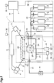
- Fig. 1 is a configurational view showing an embodiment of the enzyme reaction measuring apparatus in accordance with the present invention.
- a reaction vessel 26 is represented in section.
- this embodiment shows an infrared spectrophotometer using a spectroscope, a Fourier transform type infrared spectrophotometer or a combination of a light source emitting only an aimed wavelength of light and a detector may also be used.
- This enzyme reaction measuring apparatus is mainly composed of an infrared spectrophotometer main body 1 and an infrared spectrophotometer sample chamber 2, and further comprises respective supply sections 15 to 18 for cleaning liquid, substrate solution, enzyme solution, and stop liquid.
- the infrared spectrophotometer main body 1 incorporates therein an infrared light source 3, a spectroscope 4, an infrared light detector 5, and a control section 6 for controlling them.
- the infrared spectrophotometer sample chamber 2 mainly incorporates therein the reaction vessel 26 and a total reflection absorption prism 28.
- the infrared light source 3 is a light source for emitting infrared light.
- Infrared incident light 36 emitted from the infrared light source 3 is made incident on the entrance surface of the total reflection absorption prism 28.
- the upper surface and the lower surface are in parallel to each other, whereas the entrance surface and exit surface are formed as being inclined relative thereto.
- the infrared light incident on the entrance surface of the total reflection absorption prism 28 is propagated through the total reflection absorption prism 28 while repeating total reflection between the upper and lower surfaces thereof, so as to be emitted out of the exit surface.
- the total reflection absorption prism 28 is most preferably made of ZnSe which has a large refractive index, but also is preferably made of Ge or Si.
- the angle of incidence of the infrared light onto the lower surface of the total reflection absorption prism 28 is preferably within the range of 40 to 60 degrees, most preferably at 45 degrees.
- the smaller is the difference between the refractive index of the total reflection absorption prism 28 and the refractive index of the measurement solution 40 the deeper becomes the penetration of evanescent waves generated in the measurement solution 40 when the infrared light is totally reflected by the lower surface of the total reflection absorption prism 28, whereby the infrared absorption spectrum caused by the substrate is enhanced.
- the substrate in the measurement solution 40 can be prevented from being deposited on the total reflection absorption prism 28.
- the depth of the penetration of evanescent waves generated in the measurement solution 40 when the infrared light is totally reflected by the lower surface of the total reflection absorption prism 28 is on the order of 1/5 to 1/7 of the wavelength of infrared light. Since the aimed wavelength is about 7 ⁇ m, in order for evanescent waves of infrared light to reach the measurement solution 40, it is necessary for the Teflon coating to have a thickness of several hundred nm or less.
- Infrared transmitted light 37 emitted from the exit surface of the total reflection absorption prism 28 is made incident on the spectroscope 4.
- the spectroscope 4 chooses the aimed wavelength component of the infrared transmitted light 37.
- the infrared light detector 5 detects this aimed wavelength component, and outputs a signal corresponding to the intensity thereof.
- the signal detected by the infrared light detector 5 is transferred to an arithmetic/control computer 7 by way of the control section 6 and a data transfer line 39.
- a power supply 32 is provided in order to supply electric power to each of the infrared light source 3, spectroscope 4, infrared light detector 5, and control section 6 within the infrared spectrophotometer main body 1.
- the total reflection absorption prism 28 is attached to the reaction vessel 26 by way of a packing 27, whereby a part of the region of the lower surface of the total reflection absorption prism 28 comes into contact with the measurement solution 40 accommodated in the reaction vessel 26.
- the center portion of the packing 27 is formed with an aperture for defining the area of the region where the total reflection absorption prism 28 and the measurement solution 40 are in contact with each other.
- the packing 27 is preferably made of a material which exhibits no absorption within the wavelength range to be measured, i.e., material (made of silicone rubber or Teflon, for example) which includes neither ester group nor carboxyl group.
- the packing 27 may also be a silicone rubber type adhesive which bonds the total reflection absorption prism 28 and the reaction vessel 26 together.
- the region other than that in contact with the measurement solution 40 may be vapor-deposited with a metal (e.g., aluminum, gold, or the like), and thus deposited film may be used as the packing 27.
- the reaction vessel 26 is a vessel for accommodating the measurement solution (specifically, the substrate solution and enzyme solution).
- the side face of the reaction vessel 26 in contact with the total reflection absorption prism 28 is formed with an aperture for bringing the measurement solution 40 and the lower surface of the total reflection absorption prism 28 into contact with each other. This aperture is positioned so as to align with that formed in the packing 27.
- the material of the reaction vessel 26 is preferably Teflon or aluminum whose surface is coated with Teflon.
- the inner space of the reaction vessel 26 and the inner space of the infrared spectrophotometer sample chamber 2 are physically blocked from each other, whereby the measurement solution 40 and the infrared spectrophotometer sample chamber 2 would not directly come into contact with each other.
- a stirring rotator 22 is disposed within the reaction vessel 26.
- the stirring rotator 22, which is used for stirring the measurement solution 40 at a constant speed in order to attain a constant condition for the enzyme reaction within the reaction vessel 26, is rotated according to an instruction from a magnetic stirrer main body 21, while its rotating speed is controlled by a magnetic stirrer control section 20 to a constant speed.
- a power supply 34 is used for supplying electric power to the magnetic stirrer control section 20.
- the other side face of the reaction vessel 26 is provided with a panel heater 24.
- the panel heater 24 is used for keeping the measurement solution at a constant temperature in order to attain a constant temperature condition for the enzyme reaction within the reaction vessel 26.
- a temperature sensor 25 is disposed within the reaction vessel 26.
- the temperature sensor 25 is used for measuring temperature of the measurement solution 40 within the reaction vessel 26.
- a temperature control unit 23 is used for controlling the panel heater 24 according the temperature of the measurement solution 40 within the reaction vessel 26 measured by the temperature sensor 25, so as to keep the temperature of the measurement solution 40 within the reaction vessel 26 at a predetermined level.
- a power supply 35 is used for supplying electric power to the temperature control unit 23.
- an air discharge section 29 Connected to the reaction vessel 26 are an air discharge section 29, a solution supply pipe 30, and a solution discharge pipe 31.
- the air discharge section 29, which is used for discharging the air extruded from the inside of the reaction vessel 26 when various kinds of solutions are supplied therein, is lead from the inner space of the reaction vessel 26 to the outside of the infrared spectrophotometer sample chamber 2 by way of a solenoid valve 13 disposed therebetween.
- the solution supply pipe 30 is a pipe for supplying each of the cleaning liquid, substrate solution, enzyme solution, and stop liquid.
- the solution supply pipe 30 is a pipe for supplying each of the cleaning liquid, substrate solution, enzyme solution, and stop liquid.
- the cleaning liquid supply section 15 for supplying the cleaning liquid
- substrate solution supply section 16 for supplying the substrate solution
- enzyme solution supply section 17 for supplying the enzyme solution
- stop liquid supply section 18 for supplying the stop liquid, respectively.
- the solution discharge section 19 draws therein the measurement solution 40 accommodated within the reaction vessel 26, thereby discharging the measurement solution 40.
- the solenoid valves 8 to 14, cleaning liquid supply section 15, substrate solution supply section 16, enzyme solution supply section 17, stop liquid supply section 18, and solution discharge section 19 are connected to the arithmetic/control computer 7 by way of a control/power supply line 38 and are controlled by the arithmetic/control computer 7.
- a power supply 33 is used for supplying electric power to the arithmetic/control computer 7.
- Each of the cleaning liquid supply section 15, substrate solution supply section 16, enzyme solution supply section 17, and stop liquid supply section 18 is configured such that, according to an instruction from the arithmetic/control computer 7, it sends out a predetermined amount of its corresponding solution to the solution supply pipe 30 and sends out a predetermined amount of air or inactive gas (e.g., nitrogen gas or the like), so as to be able to quantitatively supply each solution into the reaction vessel 26 without leaving the solution within the solution supply pipe 30.
- air or inactive gas e.g., nitrogen gas or the like
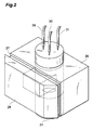
- Fig. 2 is a perspective view showing the reaction vessel 26, packing 27, and total reflection absorption prism 28 as viewed obliquely from thereabove; whereas Fig. 3 is a sectional view thereof taken along a plane perpendicular to the lower surface of the total reflection absorption prism 28.
- These drawings show the orientations of the reaction vessel 26, packing 27, and total reflection absorption prism 28 when they are actually disposed.
- one side face of the reaction vessel 26 is provided with an aperture, which is blocked by the Teflon-coated surface of the total reflection absorption prism 28.
- the lower part of the reaction vessel 26 is provided with the magnetic stirrer 21, whereas the stirring rotator 22 is disposed within the reaction vessel 26.
- the air discharge section 29, solution supply pipe 30, and solution discharge pipe 31 are lead into the inner space of the reaction vessel 26 from thereabove.
- the tips of the air discharge section 29 and solution supply pipe 30 are lead to the vicinity of the upper surface in the inner space of the reaction vessel 26, whereas the tip of the solution discharge pipe 31 is lead to the vicinity of the bottom surface in the inner space of the reaction vessel 26.
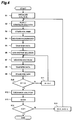
- FIG. 4 is an example of flowchart for measuring operations in the apparatus configured as mentioned above. The measuring operations will be hereinafter explained with reference to Fig. 4.
- Fig. 4 is a flowchart in the case where the number of samples to be measured is 5, and the enzyme reaction for each sample is measured 11 times at intervals of 1 minute. Also, the following processing is effected according to instructions from the arithmetic/control computer 7.
- step S1 in order to effect stable measurement, all the power supplies 32 to 35 in the apparatus are turned on before starting the measurement, and the apparatus is initialized.
- the inside of the infrared spectrophotometer sample chamber 2 is purged by dry air or nitrogen beforehand, the reaction temperature within the reaction vessel 26 is set by the temperature control unit 23, and the stirring speed of the stirring rotator 22 is set by the magnetic stirrer control section 20.
- a counter for counting the number of samples S and a counter for counting the number of measurements N each are initialized to value 0.
- all the solenoid valves 8 to 14 are in their closed state.
- step S2 the solenoid valves 13, 12, and 9 are opened, whereby a predetermined amount of a substrate solution is supplied from the substrate solution supply section 16 into the reaction vessel 26 through the solution supply pipe 30, and then a predetermined amount of nitrogen gas is supplied. After the predetermined amount of substrate solution is thus supplied into the reaction vessel 26, the solenoid valves 9 and 12 are closed.
- step S3 the apparatus is allowed to stand for 10 minutes so that the substrate solution within the reaction vessel 26 attains a preset temperature.
- the infrared absorption spectrum of the substrate solution alone is measured as background.
- the infrared incident light 36 emitted from the infrared light source 3 is made incident on the entrance surface of the total reflection absorption prism 28 and is propagated through the total reflection absorption prism 28 while being totally reflected by the upper face and lower face thereof.
- Each wavelength component of the infrared transmitted light 37 emitted out of the exit surface of the total reflection absorption prism 28 is chosen by the spectroscope 4 and is detected by the infrared light detector 5.
- the lower surface of the total reflection absorption prism 28 is in contact with the substrate solution within the reaction vessel 26, when the infrared light is totally reflected by the lower surface of the total reflection absorption prism 28, its evanescent waves are generated in the substrate solution. Also, as the infrared light repeats total reflection between the upper and lower surfaces of the total reflection absorption prism 28, the evanescent waves are generated over a wide area where the lower surface of the total reflection absorption prism 28 and the substrate solution are in contact with each other. Accordingly, the infrared transmitted light 37 emitted out of the exit surface of the total reflection absorption prism 28 is under the strong influence of absorption by the substrate solution. At step S5, thus obtained data of the infrared absorption spectrum are transferred to the arithmetic/control computer 7 by way of the control section 6.
- the solenoid valves 12 and 10 are opened, whereby a predetermined amount of an enzyme solution, which is a sample, is supplied from the enzyme solution supply section 17 into the reaction vessel 26 through the solution supply pipe 30, and then a predetermined amount of nitrogen gas is supplied, thus quantitatively supplying the enzyme solution into the reaction vessel 26. Thereafter, the solenoid valves 10 and 12 are closed.
- the infrared absorption spectrum is measured concerning the measurement solution 40 in which the substrate solution and the enzyme solution are mixed together.
- the subject of measurement at step S7 is the measurement solution, in which the substrate solution and the enzyme solution are mixed together, which is in a suspended state as being stirred by the stirring rotator 22 at a predetermined rotating speed.
- the infrared light is totally reflected by the lower surface of the total reflection absorption prism 28, its evanescent waves are generated within the measurement solution 40.
- the infrared transmitted light 37 emitted from the exit surface of the total reflection absorption prism 28 is under the influence of the substrate reduced by the reaction between the substrate and the enzyme.
- step S8 the spectrum data measured at step S7 are transferred to the arithmetic/control computer 7 by way of the control section 6. Then, the arithmetic/control computer 7 determines differences between thus transferred spectrum data and the background spectrum data that have already been transferred at step S5.
- step S9 the apparatus is allowed to stand for one minute.
- step S10 the measurement number counter N and value 10 are compared with each other in terms of magnitude. If the measurement number counter N is 10 or less, then the operation proceeds to step S11; otherwise, it proceeds to step S12.
- step S11 value 1 is added to the measurement number counter N, and then the operation returns to the spectrum measurement at step S7. Namely, in a loop constituted by steps S7 to S11, spectrum data concerning the measurement solution 40 are measured 11 times in total at intervals of 1 minute, and differences between thus measured spectrum data and the background spectrum data are determined.
- the solenoid valve 14 is opened, whereby the measurement solution within the reaction vessel 26 is discharged by the solution discharge section 19.
- the solenoid valves 12 and 8 are opened, whereby the cleaning liquid is supplied from the cleaning liquid supply section 15 to the reaction vessel 26 through the solution supply pipe 30 and, after the inside of the reaction vessel 26 is fully washed, the solenoid valve 13 is closed. Then, a predetermined amount of nitrogen gas is supplied and, after the cleaning liquid is completely discharged out of the reaction vessel 26, the solenoid valves 8, 12, and 14 are closed. Measurement of one sample is thus completed.
- step S14 the sample number counter S and value 5 are compared with each other. If the sample number counter S is less than value 5, the operation proceeds to step S15; otherwise, the measurement is completely terminated.
- step S15 the measurement number counter N is set to value 0, value 1 is added to the sample number counter S, and the operation returns to step S2. Namely, in a loop constituted by steps S2 to S15, for each of 5 samples, spectrum data concerning the measurement solution 40 are measured 11 times in total at intervals of 1 minute, and differences between thus measured spectrum data and the background spectrum data are determined.
- the arithmetic/control computer 7 obtains per-minute changes in infrared absorption spectrum caused by enzyme reactions due to enzymes in the 5 samples. From the amount of these changes, enzyme activity of each enzyme can be analyzed. Also, chemical kinetics analysis of each enzyme can be realized according to changes in infrared absorption spectrum over time.
- Reagents used are: (1) olive oil (special regent for lipase measurement) manufactured by Nakalai Tesque, Inc.; (2) polyvinyl alcohol (Kuraray POVAL, PVA-117) manufactured by Kuraray Co., Ltd.; (3) polyvinyl alcohol (Kuraray POVAL, PVA-205) manufactured by Kuraray Co., Ltd.; and (4) Lipase OF (360,000 U/g) manufactured by Meito Sangyo Co., Ltd.
- a polyvinyl alcohol solution was prepared as follows. Namely, 18.5 g of polyvinyl alcohol (Kuraray POVAL, PVA-117) and 1.5 g of polyvinyl alcohol (Kuraray POVAL, PVA-205) were mixed with about 500 ml of Milli-Q water, and the resulting mixture was stirred by a stirrer. Thereafter, the mixture was autoclaved (at 120°C for 2 to 3 minutes), and was further stirred by the stirrer so as to be completely dissolved. After this mixture liquid was cooled to room temperature, Milli-Q water was added thereto so that the total became 1 liter. After further being stirred, the mixture liquid was filtered and stored at room temperature.
- a buffer for enzyme solution (0.1-M phosphate buffer) was prepared as follows. Namely, 2.4 g of sodium dihydrogen phosphate (anhydride) were dissolved in Milli-Q water, thereby finally yielding 200 ml of Milli-Q water. Also, 7.1 g of disodium hydrogen phosphate (anhydride) were dissolved in Milli-Q water, thereby finally yielding 500 ml of Milli-Q water. Then, the above-mentioned 200 ml of sodium dihydrogen phosphate solution were placed in a beaker having a volume of 500 ml or 1 liter and set to a pH meter. The disodium hydrogen phosphate solution was further added thereto such that pH became 7.0. Thus yielded solution was filtered and then was stored under refrigeration.
- An olive oil emulsion was prepared as follows. Namely, 20 ml of olive oil (special reagent for lipase measurement) and 60 ml of polyvinyl alcohol solution were metered and were taken into a container having a volume of 150 ml. The resulting mixture was stirred by a stirrer (for 10 minutes at 2,000 rpm) while the container was surrounded by ice and cooled thereby. Thereafter, the mixture was allowed to stand for an hour while being cooled with ice.
- An enzyme solution was prepared as follows. Namely, 0.028 g of Lipase OF (360,000 U/g) was weighed and taken into a plastic test tube having a volume of 10 ml. With 10 ml of the enzyme solution buffer being added thereto, the test tube was inverted to effect mixing (1,000 U/ml) without bubbling.
- the enzyme reaction was measured by the enzyme reaction measuring apparatus and method in accordance with this embodiment.
- the temperature of the measurement solution within the reaction vessel 26 was set to 37°C by the temperature control unit 23, panel heater 24, and temperature sensor 25.
- the stirring speed of the stirring rotator 22 was set to about 1,000 rpm by the magnetic stirrer control section 20 and the magnetic stirrer main body 21.
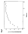
- the substrate solution 2 ml of the olive oil emulsion solution and 1.6 ml of the enzyme solution buffer were supplied into the reaction vessel 26. After they were allowed to stand for 10 minutes, background was measured, whereby background spectrum data were obtained. Then, 0.4 ml of enzyme solution was supplied into the reaction vessel 26, and spectrum was measured in total of 21 times at intervals of 1 minute over the period of 20 minutes, whereby infrared absorption spectrum data were obtained.
- Fig. 5 shows changes in absorbance at a wave number of 1,745 cm -1 in the infrared absorption spectrum from which background has been subtracted.
- the result of measurement obtained by the enzyme reaction measuring apparatus in accordance with this embodiment accords well with the result separately measured by titration method, thus indicating that the enzyme reaction can be measured by use of this apparatus.
- the enzyme reaction measuring method and its measuring apparatus in accordance with the present invention even in the case where the measurement solution has a turbidity or the case where the substrate is not water-soluble, without separating the substrate and the product from each other, the enzyme reaction can be measured continuously with a high reliability in a simple operation. Accordingly, the enzyme reaction measuring method and its measuring apparatus in accordance with the present invention are suitably used for diagnosing diseases by measuring some kinds of enzyme activities in blood or urine and judging pancreatic diseases by measuring lipase activity in blood in the sites of clinical tests, and for measuring the reaction speed of a fat or oil and lipase in an industrial process in the fat and oil chemical industry or the like.
Abstract
A method and apparatus for measuring enzyme activity
by supplying a substrate solution and an enzyme solution
into a reaction vessel combined with a total reflection
absorption prism. A measurement solution (40) in which the
enzyme solution and the substrate solution are combined
together is kept at a constant temperature within the
reaction vessel (26) by a temperature control unit (23),
and is stirred by a stirrer (21). Infrared light (36)
emitted from an infrared light source (3) is made incident
on the interface between a total reflection absorption prism
(28) disposed in contact with the measurement solution (40)
and the measurement solution (40) from the side of the total
reflection absorption prism (28) and is totally reflected
by the interface. The spectrum of transmitted infrared
light (37) thus totally reflected and emitted is detected
by an infrared light detector (5). According to thus
detected spectrum, a change in the infrared absorption
spectrum or absorbance is determined, whereby the enzyme
reaction in the measurement solution (40) is measured.
Description
The present invention relates to an enzyme reaction
measuring method and its measuring apparatus in which a
substrate solution and an enzyme solution are supplied into
a reaction vessel so as to effect a reaction, and this enzyme
reaction is continuously observed by infrared spectrometry.
Enzymes, which are a kind of catalysts produced by
organisms, are mainly composed of proteins. Reaction
materials of reactions catalyzed by the enzymes are known
as substrate. For substantially all the reactions within
living organisms, there exist enzymes corresponding
thereto; and their enzyme reactions are performed under
moderate conditions within the living organisms, thereby
contributing to maintenance of life. Accordingly, since
reduction in the action of an enzyme (enzyme activity) may
cause a disease, it is prevalent in the sites of clinical
tests to diagnose diseases by measuring activities of some
kinds of enzymes in blood and urine.
Also, enzyme reactions are highly substrate-specific
and are widely used as an energy-saving industrial process.
For example, in fat and oil chemical industry, lipase is
used for decomposing fats and oils. Lipase is an enzyme
which hydrolyzes glycerol esters (triglycerides) of
long-chain fatty acids. Lipase within alimentary canals
mainly derives from the pancreas, though part thereof is
secreted by the stomach and intestines. Lipase activity in
blood has been known to rise in pancreatic diseases.
Accordingly, the lipase activity in blood is measured to
judge the pancreatic diseases.
Measuring an enzyme reaction is to measure
quantitative and temporal changes in the substrate, which
is a reaction material of the reaction catalyzed by the
enzyme, and in a product generated by the reaction. Namely,
the greater the ratio by which the substrate changes into
the product, the higher the enzyme activity becomes. On the
other way around, the smaller the ratio is, the lower the
enzyme activity becomes. Also, when the change from the
substrate to the product is measured over time, the reaction
speed of the enzyme reaction can be analyzed.
Conventionally, in methods of measuring quantitative
changes in the substrate and product, differences in
physical or chemical properties of the substrate and product
are utilized and identified, so as to measure their
respective quantitative changes. Examples thereof
include: (1) a method in which the substrate or product is
specifically caused to develop a color after the termination
of the enzyme reaction, and is subjected to colorimetric
determination, whereby the amount of increase or decrease
in the substrate or product is determined (colorimetric
determination method); (2) a method in which a compound
labeled with a radioisotope (radioactive compound) is used
as a substrate, the fact that the product generated by the
enzyme reaction becomes a different radioactive compound
is used to separate the radioactive compounds from each other,
and the quantity of radioactivity is measured, whereby the
amount of increase or decrease in the substrate or product
is determined; (3) a fatty acid generated by the enzyme
reaction is neutralization-titrated after the termination
of the enzyme reaction (titration method); (4) a method in
which the substrate is suspended in water, and the change
in turbidity of the substrate solution upon decomposition
of the substrate by the enzyme reaction is measured, whereby
the amount of increase or decrease in the substrate or
product is determined (turbidity measurement method); (5)
a method in which, by utilizing spectroscopic differences
between the substrate and product, wavelengths of light
specifically absorbed by their respective materials
(absorption wavelengths) are used, whereby the amount of
increase or decrease in the substrate or product is
determined from change in absorbance (spectroscopic
measurement method); and the like. Among them, in
particular, the spectroscopic measurement method and
turbidity measurement method can continuously measure the
enzyme reaction.
The above-mentioned measuring methods respectively
have the following problems, however. First, in the
colorimetric determination method, a color-producing
reagent must be caused to react with the substrate or product
to specifically color the same after the termination of the
enzyme reaction, thus complicating the operation and taking
time for measurement, whereby the enzyme reaction cannot
be measured continuously. Further, when the substrate is
an aqueous suspension, it is hard to transmit light
therethrough, thus being problematic in that measurement
cannot be fully performed.
In the method using the radioisotope, since the
substrate or the product is separated after the termination
of the enzyme reaction so as to measure the quantity of
radioactivity, the operation is complicated, the
measurement takes time, and the enzyme reaction cannot be
measured continuously. Also, since the radioisotope is
used, it is problematic in terms of security and restriction
on the site of use.
Though the substrate and the product can be measured
without separation after the termination of the enzyme
reaction in the titration method, it is problematic in that
the enzyme reaction cannot be measured continuously.
Though the turbidity measurement method is easy to
operate and can continuously measure the enzyme reaction,
not the substrate itself but the light scattered from the
suspended substrate is measured. Since the enzyme reaction
itself is not observed, this method is problematic in terms
of reliability.
By contrast, the spectroscopic measurement method is
a useful means in that the enzyme reaction can be measured
easily and continuously without separating the substrate
or product. Nevertheless, in the case where the solution
to be measured has a turbidity, when the substrate is not
water-soluble in particular, it is problematic in that
quantitative measurement is difficult. It has not
conventionally been applied to a turbid sample in such an
aqueous solution. The influence of the above-mentioned
turbidity is strong in particular when the measurement
wavelength is within the range from ultraviolet to visible.
Though the turbidity becomes less influential when the
measurement wavelength is that of infrared light, it has
been known that, since the absorption of water as a solvent
is so much in the infrared range, it is necessary to use
a cell having a thickness on the order of several hundred
microns or use total reflection absorption method (Jiro
Hiraishi ed., "Furie Henkan Sekigaibunkoho (Fourier
Transform Infrared Spectroscopy)," Gakkai Shuppan Center,
(1985), pp. 163-171).
When the spectroscopic measurement method is applied
to an enzyme reaction, strict stirring is necessary due to
the dependence of the enzyme reaction on the stirring speed
and the like. In the above-mentioned cell having a
thickness on the order of several hundred microns, however,
stirring has been impossible. Further, typical measuring
apparatus for the total reflection absorption method have
failed to correctly measure enzyme activity since stirring
cannot be effected therein.
In order to eliminate the above-mentioned essential
problems resulting from spectroscopic measurement method,
it is an object of the present invention to provide an enzyme
reaction measuring method and its measuring apparatus in
which it is unnecessary for the substrate and the product
to be separated from each other, operation is easy, enzyme
reactions can be measured continuously, and enzyme
reactions can be measured with a high reliability.
The enzyme reaction measuring method in accordance
with the present invention comprises the steps of: stirring
a measurement solution containing an enzyme and a substrate
at a predetermined temperature; making infrared light
incident on an interface between a total reflection
absorption prism disposed in contact with the measurement
solution and the measurement solution from the side of the
total reflection absorption prism and totally reflected
thereby; and measuring a spectrum of thus totally reflected
infrared light so as to determine a change in an infrared
absorption spectrum or absorbance, from which an enzyme
reaction in the measurement solution is measured.
As a consequence, even in the case where the
measurement solution has a turbidity or the case where the
substrate is not water-soluble, without separating the
substrate and the product from each other, the enzyme
reaction can be measured continuously with a high
reliability in a simple operation.
Here, the enzyme catalyzes a hydrolysis reaction of
an ester bond, and is carboxylic acid ester hydrolase or
lipase.
The enzyme reaction measuring apparatus in accordance
with the present invention comprises a reaction vessel for
accommodating a measurement solution in which a substrate
solution and an enzyme solution are mixed together;
substrate solution supplying means for supplying the
substrate solution into the reaction vessel; enzyme
solution supplying means for supplying the enzyme solution
into the reaction vessel; temperature control means for
controlling temperature of the measurement solution;
stirring means for stirring the measurement solution; a
total reflection absorption prism disposed in contact with
the measurement solution; an infrared light source for
making infrared light incident on the total reflection
absorption prism such that the infrared light is totally
reflected by an interface between the total reflection
absorption prism and the measurement solution; infrared
light detecting means for measuring a spectrum of the
infrared light emitted from the total reflection absorption
prism; and an arithmetic section for determining a change
in an infrared absorption spectrum or absorbance according
to the spectrum of the infrared light measured by the
infrared light detecting means, so as to measure an enzyme
reaction in the measurement solution.
As a consequence, the substrate solution and enzyme
solution supplied to the reaction vessel respectively from
the substrate solution supplying means and enzyme solution
supplying means are mixed within the reaction vessel so as
to yield the measurement solution, which is controlled by
the temperature control means to a predetermined
temperature and is stirred by the stirring means. The
infrared light emitted from the infrared light source is
made incident on the interface between the total reflection
absorption prism disposed in contact with the measurement
solution and the measurement solution from the total
reflection absorption prism side and is totally reflected
by the interface. The spectrum of the infrared light
emitted from the total reflection absorption prism after
the total reflection is measured by the infrared detecting
means. Then, the arithmetic section determines the change
in the infrared absorption spectrum or absorbance, thereby
measuring the enzyme reaction in the measurement solution.
Accordingly, even in the case where the measurement solution
has a turbidity or the case where the substrate is not
water-soluble, without separating the substrate and the
product from each other, the enzyme reaction can be measured
continuously with a high reliability in a simple operation.
The enzyme reaction measuring apparatus in accordance
with the present invention further comprises solution
discharging means for discharging the measurement solution
in the reaction vessel, and cleaning liquid supplying means
for supplying into the reaction vessel a cleaning liquid
for cleaning the inside of the reaction vessel. As a
consequence, after the measurement of one enzyme reaction
is terminated, the measurement solution in the reaction
vessel is discharged by the solution discharging means, and
the inside of the reaction vessel is washed with the cleaning
liquid supplied by the cleaning liquid supplying means, thus
allowing the next enzyme reaction to be measured in
succession.
Of the total reflection absorption prism, at least a
region in contact with the measurement solution is coated
with Teflon. As a consequence, the substrate in the
measurement solution is prevented from being deposited on
the total reflection absorption prism.
The present invention will be explained with reference
to the accompanying drawings for further details.
Fig. 1 is a configurational view showing an embodiment
of the enzyme reaction measuring apparatus in accordance
with the present invention. In order to clarify the
configuration of this apparatus, a reaction vessel 26 is
represented in section. Though this embodiment shows an
infrared spectrophotometer using a spectroscope, a Fourier
transform type infrared spectrophotometer or a combination
of a light source emitting only an aimed wavelength of light
and a detector may also be used.
This enzyme reaction measuring apparatus is mainly
composed of an infrared spectrophotometer main body 1 and
an infrared spectrophotometer sample chamber 2, and further
comprises respective supply sections 15 to 18 for cleaning
liquid, substrate solution, enzyme solution, and stop
liquid. The infrared spectrophotometer main body 1
incorporates therein an infrared light source 3, a
spectroscope 4, an infrared light detector 5, and a control
section 6 for controlling them. The infrared
spectrophotometer sample chamber 2 mainly incorporates
therein the reaction vessel 26 and a total reflection
absorption prism 28.
The infrared light source 3 is a light source for
emitting infrared light. Infrared incident light 36
emitted from the infrared light source 3 is made incident
on the entrance surface of the total reflection absorption
prism 28. In the total reflection absorption prism 28, the
upper surface and the lower surface (surface facing the
reaction vessel 26) are in parallel to each other, whereas
the entrance surface and exit surface are formed as being
inclined relative thereto. The infrared light incident on
the entrance surface of the total reflection absorption
prism 28 is propagated through the total reflection
absorption prism 28 while repeating total reflection
between the upper and lower surfaces thereof, so as to be
emitted out of the exit surface.
The total reflection absorption prism 28 is most
preferably made of ZnSe which has a large refractive index,
but also is preferably made of Ge or Si. The angle of
incidence of the infrared light onto the lower surface of
the total reflection absorption prism 28 is preferably
within the range of 40 to 60 degrees, most preferably at
45 degrees. Here, the smaller is the difference between the
refractive index of the total reflection absorption prism
28 and the refractive index of the measurement solution 40,
the deeper becomes the penetration of evanescent waves
generated in the measurement solution 40 when the infrared
light is totally reflected by the lower surface of the total
reflection absorption prism 28, whereby the infrared
absorption spectrum caused by the substrate is enhanced.
Preferably, of the lower surface of the total
reflection absorption prism 28, at least the region in
contact with the measurement solution 40 is coated with
Teflon. As a consequence of such a Teflon coating, the
substrate in the measurement solution 40 can be prevented
from being deposited on the total reflection absorption
prism 28. Here, the depth of the penetration of evanescent
waves generated in the measurement solution 40 when the
infrared light is totally reflected by the lower surface
of the total reflection absorption prism 28 is on the order
of 1/5 to 1/7 of the wavelength of infrared light. Since
the aimed wavelength is about 7 µm, in order for evanescent
waves of infrared light to reach the measurement solution
40, it is necessary for the Teflon coating to have a thickness
of several hundred nm or less.
Infrared transmitted light 37 emitted from the exit
surface of the total reflection absorption prism 28 is made
incident on the spectroscope 4. The spectroscope 4 chooses
the aimed wavelength component of the infrared transmitted
light 37. The infrared light detector 5 detects this aimed
wavelength component, and outputs a signal corresponding
to the intensity thereof. The signal detected by the
infrared light detector 5 is transferred to an
arithmetic/control computer 7 by way of the control section
6 and a data transfer line 39. A power supply 32 is provided
in order to supply electric power to each of the infrared
light source 3, spectroscope 4, infrared light detector 5,
and control section 6 within the infrared spectrophotometer
main body 1.
The total reflection absorption prism 28 is attached
to the reaction vessel 26 by way of a packing 27, whereby
a part of the region of the lower surface of the total
reflection absorption prism 28 comes into contact with the
measurement solution 40 accommodated in the reaction vessel
26. The center portion of the packing 27 is formed with an
aperture for defining the area of the region where the total
reflection absorption prism 28 and the measurement solution
40 are in contact with each other.
The packing 27 is preferably made of a material which
exhibits no absorption within the wavelength range to be
measured, i.e., material (made of silicone rubber or Teflon,
for example) which includes neither ester group nor carboxyl
group. The packing 27 may also be a silicone rubber type
adhesive which bonds the total reflection absorption prism
28 and the reaction vessel 26 together. Alternatively, of
the lower surface of the total reflection absorption prism
28, the region other than that in contact with the
measurement solution 40 may be vapor-deposited with a metal
(e.g., aluminum, gold, or the like), and thus deposited film
may be used as the packing 27.
The reaction vessel 26 is a vessel for accommodating
the measurement solution (specifically, the substrate
solution and enzyme solution). The side face of the
reaction vessel 26 in contact with the total reflection
absorption prism 28 is formed with an aperture for bringing
the measurement solution 40 and the lower surface of the
total reflection absorption prism 28 into contact with each
other. This aperture is positioned so as to align with that
formed in the packing 27. The material of the reaction
vessel 26 is preferably Teflon or aluminum whose surface
is coated with Teflon. The inner space of the reaction
vessel 26 and the inner space of the infrared
spectrophotometer sample chamber 2 are physically blocked
from each other, whereby the measurement solution 40 and
the infrared spectrophotometer sample chamber 2 would not
directly come into contact with each other.
A stirring rotator 22 is disposed within the reaction
vessel 26. The stirring rotator 22, which is used for
stirring the measurement solution 40 at a constant speed
in order to attain a constant condition for the enzyme
reaction within the reaction vessel 26, is rotated according
to an instruction from a magnetic stirrer main body 21, while
its rotating speed is controlled by a magnetic stirrer
control section 20 to a constant speed. A power supply 34
is used for supplying electric power to the magnetic stirrer
control section 20.
The other side face of the reaction vessel 26 is
provided with a panel heater 24. The panel heater 24 is used
for keeping the measurement solution at a constant
temperature in order to attain a constant temperature
condition for the enzyme reaction within the reaction vessel
26. Also, a temperature sensor 25 is disposed within the
reaction vessel 26. The temperature sensor 25 is used for
measuring temperature of the measurement solution 40 within
the reaction vessel 26. A temperature control unit 23 is
used for controlling the panel heater 24 according the
temperature of the measurement solution 40 within the
reaction vessel 26 measured by the temperature sensor 25,
so as to keep the temperature of the measurement solution
40 within the reaction vessel 26 at a predetermined level.
A power supply 35 is used for supplying electric power to
the temperature control unit 23.
Connected to the reaction vessel 26 are an air
discharge section 29, a solution supply pipe 30, and a
solution discharge pipe 31.
The air discharge section 29, which is used for
discharging the air extruded from the inside of the reaction
vessel 26 when various kinds of solutions are supplied
therein, is lead from the inner space of the reaction vessel
26 to the outside of the infrared spectrophotometer sample
chamber 2 by way of a solenoid valve 13 disposed
therebetween.
The solution supply pipe 30 is a pipe for supplying
each of the cleaning liquid, substrate solution, enzyme
solution, and stop liquid. Connected to the solution supply
pipe 30 by way of solenoid valves 8 to 11 further through
a solenoid valve 12 are the cleaning liquid supply section
15 for supplying the cleaning liquid, substrate solution
supply section 16 for supplying the substrate solution,
enzyme solution supply section 17 for supplying the enzyme
solution, and stop liquid supply section 18 for supplying
the stop liquid, respectively.
The solution discharge pipe 31, which is a pipe for
discharging the measurement solution 40 out of the reaction
vessel 26, is connected to a solution discharge section 19
by way of a solenoid valve 14. The solution discharge
section 19 draws therein the measurement solution 40
accommodated within the reaction vessel 26, thereby
discharging the measurement solution 40.
The solenoid valves 8 to 14, cleaning liquid supply
section 15, substrate solution supply section 16, enzyme
solution supply section 17, stop liquid supply section 18,
and solution discharge section 19 are connected to the
arithmetic/control computer 7 by way of a control/power
supply line 38 and are controlled by the arithmetic/control
computer 7. A power supply 33 is used for supplying electric
power to the arithmetic/control computer 7. Each of the
cleaning liquid supply section 15, substrate solution
supply section 16, enzyme solution supply section 17, and
stop liquid supply section 18 is configured such that,
according to an instruction from the arithmetic/control
computer 7, it sends out a predetermined amount of its
corresponding solution to the solution supply pipe 30 and
sends out a predetermined amount of air or inactive gas (e.g.,
nitrogen gas or the like), so as to be able to quantitatively
supply each solution into the reaction vessel 26 without
leaving the solution within the solution supply pipe 30.
Fig. 2 is a perspective view showing the reaction
vessel 26, packing 27, and total reflection absorption prism
28 as viewed obliquely from thereabove; whereas Fig. 3 is
a sectional view thereof taken along a plane perpendicular
to the lower surface of the total reflection absorption prism
28. These drawings show the orientations of the reaction
vessel 26, packing 27, and total reflection absorption prism
28 when they are actually disposed.
As shown in these drawings, one side face of the
reaction vessel 26 is provided with an aperture, which is
blocked by the Teflon-coated surface of the total reflection
absorption prism 28. The lower part of the reaction vessel
26 is provided with the magnetic stirrer 21, whereas the
stirring rotator 22 is disposed within the reaction vessel
26. The air discharge section 29, solution supply pipe 30,
and solution discharge pipe 31 are lead into the inner space
of the reaction vessel 26 from thereabove. Among them, the
tips of the air discharge section 29 and solution supply
pipe 30 are lead to the vicinity of the upper surface in
the inner space of the reaction vessel 26, whereas the tip
of the solution discharge pipe 31 is lead to the vicinity
of the bottom surface in the inner space of the reaction
vessel 26.
In the following, an enzyme reaction measuring method
using thus configured enzyme reaction measuring apparatus
will be explained. Fig. 4 is an example of flowchart for
measuring operations in the apparatus configured as
mentioned above. The measuring operations will be
hereinafter explained with reference to Fig. 4. Here, Fig.
4 is a flowchart in the case where the number of samples
to be measured is 5, and the enzyme reaction for each sample
is measured 11 times at intervals of 1 minute. Also, the
following processing is effected according to instructions
from the arithmetic/control computer 7.
First, at step S1, in order to effect stable
measurement, all the power supplies 32 to 35 in the apparatus
are turned on before starting the measurement, and the
apparatus is initialized. Namely, the inside of the
infrared spectrophotometer sample chamber 2 is purged by
dry air or nitrogen beforehand, the reaction temperature
within the reaction vessel 26 is set by the temperature
control unit 23, and the stirring speed of the stirring
rotator 22 is set by the magnetic stirrer control section
20. Also, in the arithmetic/control computer 7, a counter
for counting the number of samples S and a counter for
counting the number of measurements N each are initialized
to value 0. At this point of time, all the solenoid valves
8 to 14 are in their closed state.
At subsequent step S2, the solenoid valves 13, 12, and
9 are opened, whereby a predetermined amount of a substrate
solution is supplied from the substrate solution supply
section 16 into the reaction vessel 26 through the solution
supply pipe 30, and then a predetermined amount of nitrogen
gas is supplied. After the predetermined amount of
substrate solution is thus supplied into the reaction vessel
26, the solenoid valves 9 and 12 are closed. At step S3,
the apparatus is allowed to stand for 10 minutes so that
the substrate solution within the reaction vessel 26 attains
a preset temperature.
At subsequent step S4, the infrared absorption
spectrum of the substrate solution alone is measured as
background. Namely, the infrared incident light 36 emitted
from the infrared light source 3 is made incident on the
entrance surface of the total reflection absorption prism
28 and is propagated through the total reflection absorption
prism 28 while being totally reflected by the upper face
and lower face thereof. Each wavelength component of the
infrared transmitted light 37 emitted out of the exit surface
of the total reflection absorption prism 28 is chosen by
the spectroscope 4 and is detected by the infrared light
detector 5.
Here, since the lower surface of the total reflection
absorption prism 28 is in contact with the substrate solution
within the reaction vessel 26, when the infrared light is
totally reflected by the lower surface of the total
reflection absorption prism 28, its evanescent waves are
generated in the substrate solution. Also, as the infrared
light repeats total reflection between the upper and lower
surfaces of the total reflection absorption prism 28, the
evanescent waves are generated over a wide area where the
lower surface of the total reflection absorption prism 28
and the substrate solution are in contact with each other.
Accordingly, the infrared transmitted light 37 emitted out
of the exit surface of the total reflection absorption prism
28 is under the strong influence of absorption by the
substrate solution. At step S5, thus obtained data of the
infrared absorption spectrum are transferred to the
arithmetic/control computer 7 by way of the control section
6.
At subsequent step S6, the solenoid valves 12 and 10
are opened, whereby a predetermined amount of an enzyme
solution, which is a sample, is supplied from the enzyme
solution supply section 17 into the reaction vessel 26
through the solution supply pipe 30, and then a predetermined
amount of nitrogen gas is supplied, thus quantitatively
supplying the enzyme solution into the reaction vessel 26.
Thereafter, the solenoid valves 10 and 12 are closed.
At subsequent step S7, the infrared absorption
spectrum is measured concerning the measurement solution
40 in which the substrate solution and the enzyme solution
are mixed together. This measurement is substantially
similar to that in the case of step S4. The subject of
measurement at step S7, however, is the measurement solution,
in which the substrate solution and the enzyme solution are
mixed together, which is in a suspended state as being
stirred by the stirring rotator 22 at a predetermined
rotating speed. Even in such a case, when the infrared light
is totally reflected by the lower surface of the total
reflection absorption prism 28, its evanescent waves are
generated within the measurement solution 40. In this case,
the infrared transmitted light 37 emitted from the exit
surface of the total reflection absorption prism 28 is under
the influence of the substrate reduced by the reaction
between the substrate and the enzyme.
At step S8, the spectrum data measured at step S7 are
transferred to the arithmetic/control computer 7 by way of
the control section 6. Then, the arithmetic/control
computer 7 determines differences between thus transferred
spectrum data and the background spectrum data that have
already been transferred at step S5.
At subsequent step S9, the apparatus is allowed to
stand for one minute. At step S10, the measurement number
counter N and value 10 are compared with each other in terms
of magnitude. If the measurement number counter N is 10 or
less, then the operation proceeds to step S11; otherwise,
it proceeds to step S12. At step S11, value 1 is added to
the measurement number counter N, and then the operation
returns to the spectrum measurement at step S7. Namely, in
a loop constituted by steps S7 to S11, spectrum data
concerning the measurement solution 40 are measured 11 times
in total at intervals of 1 minute, and differences between
thus measured spectrum data and the background spectrum data
are determined.
At step S12, the solenoid valve 14 is opened, whereby
the measurement solution within the reaction vessel 26 is
discharged by the solution discharge section 19. At step
S13, the solenoid valves 12 and 8 are opened, whereby the
cleaning liquid is supplied from the cleaning liquid supply
section 15 to the reaction vessel 26 through the solution
supply pipe 30 and, after the inside of the reaction vessel
26 is fully washed, the solenoid valve 13 is closed. Then,
a predetermined amount of nitrogen gas is supplied and, after
the cleaning liquid is completely discharged out of the
reaction vessel 26, the solenoid valves 8, 12, and 14 are
closed. Measurement of one sample is thus completed.
At subsequent step S14, the sample number counter S
and value 5 are compared with each other. If the sample
number counter S is less than value 5, the operation proceeds
to step S15; otherwise, the measurement is completely
terminated. At step S15, the measurement number counter N
is set to value 0, value 1 is added to the sample number
counter S, and the operation returns to step S2. Namely,
in a loop constituted by steps S2 to S15, for each of 5 samples,
spectrum data concerning the measurement solution 40 are
measured 11 times in total at intervals of 1 minute, and
differences between thus measured spectrum data and the
background spectrum data are determined.
Accordingly, as the foregoing operations are
performed, the arithmetic/control computer 7 obtains
per-minute changes in infrared absorption spectrum caused
by enzyme reactions due to enzymes in the 5 samples. From
the amount of these changes, enzyme activity of each enzyme
can be analyzed. Also, chemical kinetics analysis of each
enzyme can be realized according to changes in infrared
absorption spectrum over time.
In the following, the present invention will be
specifically explained with reference to Examples, though
the present invention should net be restricted the following
Examples as long as it does not exceed the gist thereof.
Examples of enzyme reaction measurement effected by the
above-mentioned apparatus will be shown hereinafter.
Reagents used are: (1) olive oil (special regent for
lipase measurement) manufactured by Nakalai Tesque, Inc.;
(2) polyvinyl alcohol (Kuraray POVAL, PVA-117) manufactured
by Kuraray Co., Ltd.; (3) polyvinyl alcohol (Kuraray POVAL,
PVA-205) manufactured by Kuraray Co., Ltd.; and (4) Lipase
OF (360,000 U/g) manufactured by Meito Sangyo Co., Ltd.
A polyvinyl alcohol solution was prepared as follows.
Namely, 18.5 g of polyvinyl alcohol (Kuraray POVAL, PVA-117)
and 1.5 g of polyvinyl alcohol (Kuraray POVAL, PVA-205) were
mixed with about 500 ml of Milli-Q water, and the resulting
mixture was stirred by a stirrer. Thereafter, the mixture
was autoclaved (at 120°C for 2 to 3 minutes), and was further
stirred by the stirrer so as to be completely dissolved.
After this mixture liquid was cooled to room temperature,
Milli-Q water was added thereto so that the total became
1 liter. After further being stirred, the mixture liquid
was filtered and stored at room temperature.
A buffer for enzyme solution (0.1-M phosphate buffer)
was prepared as follows. Namely, 2.4 g of sodium
dihydrogen phosphate (anhydride) were dissolved in Milli-Q
water, thereby finally yielding 200 ml of Milli-Q water.
Also, 7.1 g of disodium hydrogen phosphate (anhydride) were
dissolved in Milli-Q water, thereby finally yielding 500
ml of Milli-Q water. Then, the above-mentioned 200 ml of
sodium dihydrogen phosphate solution were placed in a beaker
having a volume of 500 ml or 1 liter and set to a pH meter.
The disodium hydrogen phosphate solution was further added
thereto such that pH became 7.0. Thus yielded solution was
filtered and then was stored under refrigeration.
An olive oil emulsion was prepared as follows. Namely,
20 ml of olive oil (special reagent for lipase measurement)
and 60 ml of polyvinyl alcohol solution were metered and
were taken into a container having a volume of 150 ml. The
resulting mixture was stirred by a stirrer (for 10 minutes
at 2,000 rpm) while the container was surrounded by ice and
cooled thereby. Thereafter, the mixture was allowed to
stand for an hour while being cooled with ice.
An enzyme solution was prepared as follows. Namely,
0.028 g of Lipase OF (360,000 U/g) was weighed and taken
into a plastic test tube having a volume of 10 ml. With 10
ml of the enzyme solution buffer being added thereto, the
test tube was inverted to effect mixing (1,000 U/ml) without
bubbling.
For each of thus prepared substrate solution (olive
oil emulsion solution and enzyme solution buffer) and enzyme
solution, the enzyme reaction was measured by the enzyme
reaction measuring apparatus and method in accordance with
this embodiment. The temperature of the measurement
solution within the reaction vessel 26 was set to 37°C by
the temperature control unit 23, panel heater 24, and
temperature sensor 25. The stirring speed of the stirring
rotator 22 was set to about 1,000 rpm by the magnetic stirrer
control section 20 and the magnetic stirrer main body 21.
First, as the substrate solution, 2 ml of the olive
oil emulsion solution and 1.6 ml of the enzyme solution
buffer were supplied into the reaction vessel 26. After
they were allowed to stand for 10 minutes, background was
measured, whereby background spectrum data were obtained.
Then, 0.4 ml of enzyme solution was supplied into the
reaction vessel 26, and spectrum was measured in total of
21 times at intervals of 1 minute over the period of 20
minutes, whereby infrared absorption spectrum data were
obtained.
From the infrared absorption spectrum data concerning
the measurement solution in which the enzyme solution and
the substrate solution are mixed together, the background
spectrum data are subtracted. The reaction speed of the
enzyme reaction is obtained according to the result thereof.
Fig. 5 shows changes in absorbance at a wave number of 1,745
cm-1 in the infrared absorption spectrum from which
background has been subtracted. The result of measurement
obtained by the enzyme reaction measuring apparatus in
accordance with this embodiment accords well with the result
separately measured by titration method, thus indicating
that the enzyme reaction can be measured by use of this
apparatus.
As explained in the foregoing, in the enzyme reaction
measuring method and its measuring apparatus in accordance
with the present invention, even in the case where the
measurement solution has a turbidity or the case where the
substrate is not water-soluble, without separating the
substrate and the product from each other, the enzyme
reaction can be measured continuously with a high
reliability in a simple operation. Accordingly, the enzyme
reaction measuring method and its measuring apparatus in
accordance with the present invention are suitably used for
diagnosing diseases by measuring some kinds of enzyme
activities in blood or urine and judging pancreatic diseases
by measuring lipase activity in blood in the sites of
clinical tests, and for measuring the reaction speed of a
fat or oil and lipase in an industrial process in the fat
and oil chemical industry or the like.
Claims (7)
- An enzyme reaction measuring method comprising the steps of: stirring a measurement solution containing an enzyme and a substrate at a predetermined temperature; making infrared light incident on an interface between a total reflection absorption prism disposed in contact with said measurement solution and said measurement solution from the side of said total reflection absorption prism and totally reflected thereby; and measuring a spectrum of thus totally reflected infrared light so as to determine a change in an infrared absorption spectrum or absorbance, from which an enzyme reaction in said measurement solution is measured.
- An enzyme reaction measuring method according to claim 1, wherein said enzyme catalyzes a hydrolysis reaction of an ester bond.
- An enzyme reaction measuring method according to claim 2, wherein said enzyme is carboxylic acid ester hydrolase.
- An enzyme reaction measuring method according to claim 2, wherein said enzyme is lipase.
- An enzyme reaction measuring apparatus comprising:a reaction vessel for accommodating a measurement solution in which a substrate solution and an enzyme solution are mixed together;substrate solution supplying means for supplying said substrate solution into said reaction vessel;enzyme solution supplying means for supplying said enzyme solution into said reaction vessel;temperature control means for controlling temperature of said measurement solution;stirring means for stirring said measurement solution;a total reflection absorption prism disposed in contact with said measurement solution;an infrared light source for making infrared light incident on said total reflection absorption prism such that said infrared light is totally reflected by an interface between said total reflection absorption prism and said measurement solution;infrared light detecting means for measuring a spectrum of said infrared light emitted from said total reflection absorption prism; andan arithmetic section for determining a change in an infrared absorption spectrum or absorbance according to said spectrum of said infrared light measured by said infrared light detecting means, so as to measure an enzyme reaction in said measurement solution.
- An enzyme reaction measuring apparatus according to claim 5, further comprising:solution discharging means for discharging said measurement solution in said reaction vessel; andcleaning liquid supplying means for supplying into said reaction vessel a cleaning liquid for cleaning the inside of said reaction vessel.
- An enzyme reaction measuring apparatus according to claim 5, wherein, of said total reflection absorption prism, at least a region in contact with said measurement solution is coated with Teflon.
Applications Claiming Priority (3)
| Application Number | Priority Date | Filing Date | Title |
|---|---|---|---|
| JP41805/96 | 1996-02-28 | ||
| JP4180596 | 1996-02-28 | ||
| PCT/JP1997/000513 WO1997032198A1 (en) | 1996-02-28 | 1997-02-24 | Method and apparatus for assaying enzymatic reaction |
Publications (2)
| Publication Number | Publication Date |
|---|---|
| EP0884584A1 true EP0884584A1 (en) | 1998-12-16 |
| EP0884584A4 EP0884584A4 (en) | 1998-12-30 |
Family
ID=12618555
Family Applications (1)
| Application Number | Title | Priority Date | Filing Date |
|---|---|---|---|
| EP97904619A Withdrawn EP0884584A1 (en) | 1996-02-28 | 1997-02-24 | Method and apparatus for assaying enzymatic reaction |
Country Status (4)
| Country | Link |
|---|---|
| US (1) | US5905030A (en) |
| EP (1) | EP0884584A1 (en) |
| JP (1) | JP3090692B2 (en) |
| WO (1) | WO1997032198A1 (en) |
Cited By (10)
| Publication number | Priority date | Publication date | Assignee | Title |
|---|---|---|---|---|
| EP1032821A4 (en) * | 1997-11-12 | 2002-07-31 | Millennium Pharm Inc | Methods for identifying biological macromolecule interactions with compounds |
| WO2003083458A2 (en) * | 2002-04-03 | 2003-10-09 | Johann Wolfgang Goethe-Universität Frankfurt am Main | Infrared measuring device, especially for the spectrometry of aqueous systems, preferably multiple component systems |
| FR2864848A1 (en) * | 2004-01-07 | 2005-07-08 | Patrick Prevost | Perfected device for infra-red spectroscopy with a waveguide between the light source and an internal reflection element forming part of a measuring cell into which a sample is introduced |
| WO2006127724A2 (en) * | 2005-05-23 | 2006-11-30 | Optiscan Biomedical Corporation | Spectroscopic analysis of a biological fluid reacted with an enzyme |
| US8140140B2 (en) | 2005-02-14 | 2012-03-20 | Optiscan Biomedical Corporation | Analyte detection system for multiple analytes |
| WO2013008003A1 (en) * | 2011-07-11 | 2013-01-17 | M Squared Lasers Limited | Maturation apparatus and methods |
| US9091676B2 (en) | 2010-06-09 | 2015-07-28 | Optiscan Biomedical Corp. | Systems and methods for measuring multiple analytes in a sample |
| US9289169B2 (en) | 2007-05-18 | 2016-03-22 | Optiscan Biomedical Corp. | Analyte monitoring systems and methods |
| US9913604B2 (en) | 2005-02-14 | 2018-03-13 | Optiscan Biomedical Corporation | Analyte detection systems and methods using multiple measurements |
| US10416036B2 (en) | 2013-05-22 | 2019-09-17 | M Squared Lasers Limited | Maturation monitoring apparatus and methods |
Families Citing this family (5)
| Publication number | Priority date | Publication date | Assignee | Title |
|---|---|---|---|---|
| AU6343398A (en) * | 1997-02-28 | 1998-09-18 | Cepheid | Heat exchanging, optically interrogated chemical reaction assembly |
| JP2000162124A (en) * | 1998-12-01 | 2000-06-16 | Nippon Laser Denshi Kk | Sensor chip for surface plasmon resonance angle detecting device |
| AU6347100A (en) * | 1999-07-16 | 2001-02-05 | Human Genome Sciences, Inc. | Real-time, in situ biomanufacturing process monitoring and control in response to ir spectroscopy |
| US8629399B2 (en) * | 2009-09-22 | 2014-01-14 | Bp Corporation North America Inc. | Methods and apparatuses for measuring biological processes using mid-infrared spectroscopy |
| JP5883314B2 (en) * | 2011-09-02 | 2016-03-15 | 日本インスツルメンツ株式会社 | Reduced vaporization mercury analyzer |
Citations (4)
| Publication number | Priority date | Publication date | Assignee | Title |
|---|---|---|---|---|
| DE3701833A1 (en) * | 1986-02-03 | 1987-08-06 | Avl Ag | Method for the optical determination of a catalytic enzyme activity of a sample, and an arrangement for carrying out the method |
| GB2217834A (en) * | 1988-04-29 | 1989-11-01 | Mine Safety Appliances Co | Evanescent sensor |
| WO1990005295A1 (en) * | 1988-11-10 | 1990-05-17 | Pharmacia Ab | Optical biosensor system |
| US5170056A (en) * | 1991-02-28 | 1992-12-08 | Galileo Electro-Optics Corporation | Optical fiber coupled devices for remote spectroscopy in the infrared |
Family Cites Families (7)
| Publication number | Priority date | Publication date | Assignee | Title |
|---|---|---|---|---|
| US4022667A (en) * | 1975-09-22 | 1977-05-10 | The University Of Alabama | Substrate solution for carboxylic ester hydrolase determination |
| JPS63263446A (en) * | 1986-03-25 | 1988-10-31 | チバ コ−ニング ダイアグノステイクス コ−ポレ−シヨン | Infinite small wave sensor |
| JPH0560686A (en) * | 1991-09-03 | 1993-03-12 | Kao Corp | Sebum component measurement device |
| JP3011825B2 (en) * | 1992-08-07 | 2000-02-21 | 新日本製鐵株式会社 | Oil saponification value / acid value and fatty acid iron measurement method |
| JP3227866B2 (en) * | 1993-02-17 | 2001-11-12 | 住友電気工業株式会社 | Method and apparatus for measuring curing reaction |
| EP0714024B1 (en) * | 1994-11-25 | 2002-01-30 | Kyoto Dai-ichi Kagaku Co., Ltd. | Method of and apparatus for determining hydrogen peroxide |
| JPH08145879A (en) * | 1994-11-25 | 1996-06-07 | Kdk Corp | Determination method and device for hydrogen peroxide |
-
1997
- 1997-02-24 WO PCT/JP1997/000513 patent/WO1997032198A1/en not_active Application Discontinuation
- 1997-02-24 JP JP53078397A patent/JP3090692B2/en not_active Expired - Fee Related
- 1997-02-24 EP EP97904619A patent/EP0884584A1/en not_active Withdrawn
- 1997-02-24 US US09/077,928 patent/US5905030A/en not_active Expired - Fee Related
Patent Citations (4)
| Publication number | Priority date | Publication date | Assignee | Title |
|---|---|---|---|---|
| DE3701833A1 (en) * | 1986-02-03 | 1987-08-06 | Avl Ag | Method for the optical determination of a catalytic enzyme activity of a sample, and an arrangement for carrying out the method |
| GB2217834A (en) * | 1988-04-29 | 1989-11-01 | Mine Safety Appliances Co | Evanescent sensor |
| WO1990005295A1 (en) * | 1988-11-10 | 1990-05-17 | Pharmacia Ab | Optical biosensor system |
| US5170056A (en) * | 1991-02-28 | 1992-12-08 | Galileo Electro-Optics Corporation | Optical fiber coupled devices for remote spectroscopy in the infrared |
Non-Patent Citations (1)
| Title |
|---|
| See also references of WO9732198A1 * |
Cited By (16)
| Publication number | Priority date | Publication date | Assignee | Title |
|---|---|---|---|---|
| EP1032821A4 (en) * | 1997-11-12 | 2002-07-31 | Millennium Pharm Inc | Methods for identifying biological macromolecule interactions with compounds |
| US7812312B2 (en) | 2002-04-03 | 2010-10-12 | Johann Wolfgang Goethe-Universitaet | Infrared measuring device, especially for the spectrometry of aqueous systems, preferably multiple component systems |
| EP1715327A2 (en) * | 2002-04-03 | 2006-10-25 | Johann Wolfgang Goethe-Universität Frankfurth am Main | Infrared measuring device, especially for the spectrometry of aqueous systems, preferably multiple component systems |
| WO2003083458A2 (en) * | 2002-04-03 | 2003-10-09 | Johann Wolfgang Goethe-Universität Frankfurt am Main | Infrared measuring device, especially for the spectrometry of aqueous systems, preferably multiple component systems |
| EP1715327A3 (en) * | 2002-04-03 | 2007-01-10 | Johann Wolfgang Goethe-Universität Frankfurth am Main | Infrared measuring device, especially for the spectrometry of aqueous systems, preferably multiple component systems |
| WO2003083458A3 (en) * | 2002-04-03 | 2003-12-31 | Univ Jw Goethe Frankfurt Main | Infrared measuring device, especially for the spectrometry of aqueous systems, preferably multiple component systems |
| FR2864848A1 (en) * | 2004-01-07 | 2005-07-08 | Patrick Prevost | Perfected device for infra-red spectroscopy with a waveguide between the light source and an internal reflection element forming part of a measuring cell into which a sample is introduced |
| US9913604B2 (en) | 2005-02-14 | 2018-03-13 | Optiscan Biomedical Corporation | Analyte detection systems and methods using multiple measurements |
| US8140140B2 (en) | 2005-02-14 | 2012-03-20 | Optiscan Biomedical Corporation | Analyte detection system for multiple analytes |
| WO2006127724A2 (en) * | 2005-05-23 | 2006-11-30 | Optiscan Biomedical Corporation | Spectroscopic analysis of a biological fluid reacted with an enzyme |
| WO2006127724A3 (en) * | 2005-05-23 | 2007-03-29 | Optiscan Biomedical Corp | Spectroscopic analysis of a biological fluid reacted with an enzyme |
| US9289169B2 (en) | 2007-05-18 | 2016-03-22 | Optiscan Biomedical Corp. | Analyte monitoring systems and methods |
| US9091676B2 (en) | 2010-06-09 | 2015-07-28 | Optiscan Biomedical Corp. | Systems and methods for measuring multiple analytes in a sample |
| WO2013008003A1 (en) * | 2011-07-11 | 2013-01-17 | M Squared Lasers Limited | Maturation apparatus and methods |
| US9383314B2 (en) | 2011-07-11 | 2016-07-05 | M Squared Lasers Limited | Maturation apparatus and methods |
| US10416036B2 (en) | 2013-05-22 | 2019-09-17 | M Squared Lasers Limited | Maturation monitoring apparatus and methods |
Also Published As
| Publication number | Publication date |
|---|---|
| US5905030A (en) | 1999-05-18 |
| WO1997032198A1 (en) | 1997-09-04 |
| EP0884584A4 (en) | 1998-12-30 |
| JP3090692B2 (en) | 2000-09-25 |
Similar Documents
| Publication | Publication Date | Title |
|---|---|---|
| US5905030A (en) | Method and apparatus for assaying enzymatic reaction | |
| US7812312B2 (en) | Infrared measuring device, especially for the spectrometry of aqueous systems, preferably multiple component systems | |
| AU2005208255B2 (en) | A handheld device with a disposable element for chemical analysis of multiple analytes | |
| CA2750538C (en) | Device and method for detection of humidity-compromised urine test strips | |
| Wolfbeis | Fibre-optic sensors in biomedical sciences | |
| JP2003520942A (en) | Reagent-free analysis of biological samples | |
| Walters et al. | Fiber-optic biosensor for ethanol, based on an internal enzyme concept | |
| EP0588831A1 (en) | Analytical methods | |
| Díaz et al. | Sol-gel cholinesterase biosensor for organophosphorus pesticide fluorimetric analysis | |
| AU670099B2 (en) | Sensor for optical assay | |
| JPS62185148A (en) | Method for optically determining enzyme activity by catalytic reaction of sample and system for executing said method | |
| US4857454A (en) | Spectrophotometric method for kinetic absorbance measurements in two-phase enzyme immunoassay and apparatus therefor | |
| Haberkorn et al. | A mid-IR flow-through sensor for direct monitoring of enzyme catalysed reactions. Case study: measurement of carbohydrates in beer | |
| Owen | Non-electrode biosensors in clinical biochemistry | |
| US5272061A (en) | Assay for serum cholinesterase activity | |
| JPS63274840A (en) | Process supervisory and controlling equipment | |
| US20020110487A1 (en) | Apparatus and method for handling fluids | |
| CN111829991A (en) | beta-CD-based reflective optical fiber cholesterol sensor and preparation method thereof | |
| US6118541A (en) | Method to determine the effectiveness of a chemical mixing system | |
| CN106605144A (en) | Methods and systems for point-of-care coagulation assays by optical detection | |
| Tarca et al. | A new optic fiber sensor for measuring the concentration of ethanol in wine | |
| JPH03164195A (en) | Analysis of liquid specimen and apparatus therefor | |
| WO1995020051A1 (en) | Optical chemical sensors based on enzyme inhibition | |
| JP2020521122A (en) | Porous optical fiber for detecting analytes in fluids | |
| CN219104729U (en) | SPR sensor |
Legal Events
| Date | Code | Title | Description |
|---|---|---|---|
| PUAI | Public reference made under article 153(3) epc to a published international application that has entered the european phase |
Free format text: ORIGINAL CODE: 0009012 |
|
| 17P | Request for examination filed |
Effective date: 19980824 |
|
| AK | Designated contracting states |
Kind code of ref document: A1 Designated state(s): DE GB |
|
| A4 | Supplementary search report drawn up and despatched |
Effective date: 19981112 |
|
| AK | Designated contracting states |
Kind code of ref document: A4 Designated state(s): DE GB |
|
| STAA | Information on the status of an ep patent application or granted ep patent |
Free format text: STATUS: THE APPLICATION HAS BEEN WITHDRAWN |
|
| 18W | Application withdrawn |
Withdrawal date: 20020128 |