EP0883251B1 - Power control of mobile station transmission during handoff in a cellular system - Google Patents
Power control of mobile station transmission during handoff in a cellular system Download PDFInfo
- Publication number
- EP0883251B1 EP0883251B1 EP98304471A EP98304471A EP0883251B1 EP 0883251 B1 EP0883251 B1 EP 0883251B1 EP 98304471 A EP98304471 A EP 98304471A EP 98304471 A EP98304471 A EP 98304471A EP 0883251 B1 EP0883251 B1 EP 0883251B1
- Authority
- EP
- European Patent Office
- Prior art keywords
- base station
- mobile station
- power
- message
- received
- Prior art date
- Legal status (The legal status is an assumption and is not a legal conclusion. Google has not performed a legal analysis and makes no representation as to the accuracy of the status listed.)
- Expired - Lifetime
Links
- 230000005540 biological transmission Effects 0.000 title claims description 64
- 230000001413 cellular effect Effects 0.000 title description 17
- 238000000034 method Methods 0.000 claims description 45
- 238000005259 measurement Methods 0.000 claims description 43
- 238000012545 processing Methods 0.000 claims description 4
- 230000008569 process Effects 0.000 description 27
- 238000010586 diagram Methods 0.000 description 12
- 238000012937 correction Methods 0.000 description 9
- 239000000523 sample Substances 0.000 description 7
- 230000004044 response Effects 0.000 description 6
- 238000004891 communication Methods 0.000 description 5
- 230000006870 function Effects 0.000 description 5
- 238000001228 spectrum Methods 0.000 description 5
- CIWBSHSKHKDKBQ-JLAZNSOCSA-N Ascorbic acid Chemical compound OC[C@H](O)[C@H]1OC(=O)C(O)=C1O CIWBSHSKHKDKBQ-JLAZNSOCSA-N 0.000 description 4
- 230000008901 benefit Effects 0.000 description 2
- 239000000969 carrier Substances 0.000 description 2
- 238000012790 confirmation Methods 0.000 description 2
- 238000012986 modification Methods 0.000 description 2
- 230000004048 modification Effects 0.000 description 2
- 230000008859 change Effects 0.000 description 1
- 230000001934 delay Effects 0.000 description 1
- 230000000694 effects Effects 0.000 description 1
- 238000005562 fading Methods 0.000 description 1
- 238000010295 mobile communication Methods 0.000 description 1
- 230000008054 signal transmission Effects 0.000 description 1
Images


Classifications
-
- H—ELECTRICITY
- H04—ELECTRIC COMMUNICATION TECHNIQUE
- H04W—WIRELESS COMMUNICATION NETWORKS
- H04W52/00—Power management, e.g. TPC [Transmission Power Control], power saving or power classes
- H04W52/04—TPC
- H04W52/18—TPC being performed according to specific parameters
- H04W52/28—TPC being performed according to specific parameters using user profile, e.g. mobile speed, priority or network state, e.g. standby, idle or non transmission
- H04W52/283—Power depending on the position of the mobile
-
- H—ELECTRICITY
- H04—ELECTRIC COMMUNICATION TECHNIQUE
- H04W—WIRELESS COMMUNICATION NETWORKS
- H04W52/00—Power management, e.g. TPC [Transmission Power Control], power saving or power classes
- H04W52/04—TPC
- H04W52/38—TPC being performed in particular situations
- H04W52/40—TPC being performed in particular situations during macro-diversity or soft handoff
-
- H—ELECTRICITY
- H04—ELECTRIC COMMUNICATION TECHNIQUE
- H04W—WIRELESS COMMUNICATION NETWORKS
- H04W36/00—Hand-off or reselection arrangements
- H04W36/08—Reselecting an access point
-
- H—ELECTRICITY
- H04—ELECTRIC COMMUNICATION TECHNIQUE
- H04W—WIRELESS COMMUNICATION NETWORKS
- H04W52/00—Power management, e.g. TPC [Transmission Power Control], power saving or power classes
- H04W52/04—TPC
- H04W52/06—TPC algorithms
- H04W52/14—Separate analysis of uplink or downlink
- H04W52/143—Downlink power control
-
- H—ELECTRICITY
- H04—ELECTRIC COMMUNICATION TECHNIQUE
- H04W—WIRELESS COMMUNICATION NETWORKS
- H04W52/00—Power management, e.g. TPC [Transmission Power Control], power saving or power classes
- H04W52/04—TPC
- H04W52/06—TPC algorithms
- H04W52/14—Separate analysis of uplink or downlink
- H04W52/146—Uplink power control
-
- H—ELECTRICITY
- H04—ELECTRIC COMMUNICATION TECHNIQUE
- H04W—WIRELESS COMMUNICATION NETWORKS
- H04W52/00—Power management, e.g. TPC [Transmission Power Control], power saving or power classes
- H04W52/04—TPC
- H04W52/18—TPC being performed according to specific parameters
- H04W52/24—TPC being performed according to specific parameters using SIR [Signal to Interference Ratio] or other wireless path parameters
- H04W52/242—TPC being performed according to specific parameters using SIR [Signal to Interference Ratio] or other wireless path parameters taking into account path loss
-
- H—ELECTRICITY
- H04—ELECTRIC COMMUNICATION TECHNIQUE
- H04W—WIRELESS COMMUNICATION NETWORKS
- H04W52/00—Power management, e.g. TPC [Transmission Power Control], power saving or power classes
- H04W52/04—TPC
- H04W52/38—TPC being performed in particular situations
- H04W52/50—TPC being performed in particular situations at the moment of starting communication in a multiple access environment
Definitions
- This invention relates to handoff in cellular telecommunications systems and, more particularly to an apparatus and method for controlling the transmission power of a mobile station during handoff of a call between base stations of a cellular system.
- CDMA Code Division Multiple Access
- CDMA provides several advantages over conventional frequency division multiple access (FDMA) or time division multiple access (TDMA) systems.
- FDMA frequency division multiple access
- TDMA time division multiple access
- users are assigned a unique frequency for each of mobile to base (uplink or reverse link) and base to mobile (downlink or forward link) communications.
- TDMA time division multiple access
- users are each assigned a unique frequency, for the uplink and downlink, and a unique time period in which to transmit or receive on that frequency.
- FDMA and TDMA systems require planning for allocation of channel frequencies and/or time periods on these frequencies to mobile stations and base stations.
- a power control process may be used to control each mobile station's transmission power level so that the signal level received at the base station from each mobile station is as close as possible to a single predetermined level. Additionally, the power control process may also be used to assure that the received signal levels at the base station are of an adequate level, so that calls are not dropped.
- CDMA mobile station power control scheme is the power control used by systems specified in the Telecommunications Industry Association/ Electronic Industries Association (TIA/EIA) IS-95 standard.
- TIA/EIA Telecommunications Industry Association/ Electronic Industries Association
- PCS personal communications systems
- a mobile station In the IS-95 power control process, a mobile station first adjusts its transmission power level using an access channel assigned to a base station through which the mobile station is attempting to gain access to the system. To gain access the mobile station follows an open loop power control process that involves transmitting access probe transmissions at a relatively low power level on the access channel and gradually increasing the level of subsequent access probe transmissions, in access probe correction increments set by the system, until a response is obtained from the system and the mobile station gains access to the system.
- the ANSI-008 standard equation is similar, but because of the frequency difference, has a constant equal to 76 instead of 73, and also includes an additional value that is added to increase the range of NOM_PWR, the additional value being defined as 16*NOM_PWR_EXT, which is a system parameter. IS-95 could also be modified to include a similar value.
- the mobile station waits in an idle mode until a call is initiated from either the mobile station to the base station, or from the base station to the mobile station.
- a reverse traffic channel and a forward traffic channel are then assigned for the call.
- the mobile station When transmitting on the IS-95 reverse traffic channel, the mobile station initializes at the level set on the access channel by the open loop process defined by equation (1). Once the reverse traffic channel transmission power level is initialized and the call begins, the system and mobile station then also begin a closed loop power control process.
- the closed loop power control process allows the signal level received at the base station from each mobile station transmitting on a reverse traffic channel to be set as close as possible to a single predetermined level.
- the base station transmits closed loop power control corrections in the form of power control bits to the mobile station in a power control subchannel that is included in the forward traffic channel.
- a single power control bit is transmitted in the power control subchannel every 1.25ms.
- a "one" bit transmitted in the power control subchannel indicates that the mobile station should increase its transmission power 1 db, while a "zero" bit indicates that the mobile station should decrease its transmission power 1db.
- the mobile station adjusts its output power level up or down in an increment of 1db.
- mean output power(dBm) -mean input power (dBm) -73 + NOM_PWR (dBm) + INIT_PWR (dBm) + the sum of all access probe corrections + the sum of all closed loop power control corrections
- the ANSI-008 standard equation is similar, but because of the frequency difference, has a constant equal to 76 instead of 73, and also includes an additional value that is added to increase the range of NOM_PWR, the additional value defined as 16*NOM_PWR_EXT, which is a system parameter.
- a handoff of the call from one base station to another base station may occur as the mobile station moves throughout the system.
- two types of handoff are possible.
- a soft handoff occurs when the mobile station commences communications with the new base station without interrupting communications with the old base station.
- Soft handoff can only be used between CDMA traffic channels having identical channel frequency assignments.
- a CDMA to CDMA hard handoff occurs when the mobile station is transitioned between two disjoint sets of base stations, different frequency assignments, or different traffic channel frame offsets.
- the system continues to use the open loop power control process to adjust the transmission power of the mobile station on the reverse traffic channel as the mobile switches to the traffic channels of the new base station.
- a value of a nominal power (NOM_PWR) setting for the target cell is transmitted to the mobile station in a handoff message.
- the nominal power(NOM_PWR) setting is then used to set an initial power transmission level on the traffic channel of the new base station.
- the base station in a particular cell may have a different desired received signal strength for signals received from mobile stations, as compared to another cell's base station's desired received signal strength for signals received from mobile stations. If this difference exists between neighboring cells, a problem could occur during handoff of a call between the neighboring cells. If the handoff is from a higher power cell to a lower power cell, there could be a potential near-far problem among the mobile stations in the new cell.
- the mobile station involved in the call handoff may initially be at a power level much greater than other mobile stations in the new cell.
- the signal from the mobile station involved in the call handoff may then overwhelm the signals from the other mobile stations at the base station causing a near far problem. If the handoff is from a lower power cell to a higher power cell, there could be a potential dropped call problem.
- the mobile station involved in the call handoff may initially be at a power level much lower than other mobile stations in the new cell. The signal strength received at the new base station from the mobile station in call handoff may not be adequate to maintain the connection on the reverse link, and a dropped call could occur in this situation.
- the power control process used may not be adequate to avoid problems in call handoff between cells of different sizes.
- the variable of the mean input power used in equations (1) will not cause a significant change in mobile station transmission power.
- the transmission power level of the mobile station is adjusted at hard handoff by the new base station transmitting a new NOM_PWR value to the mobile station.
- the NOM_PWR value is typically an estimated value, set to adjust the mobile station transmission power level to an appropriate initial level in the target cell.
- the new NOM_PWR value is then used in the mobile station to calculate a new mean output power, as given by equation (1) above for the initial transmission of the mobile station on the reverse traffic channel after handoff.
- the range of the value of NOM_PWR is from -8dB to 7dB.
- the value 16* NOM_PWR_EXT is used along with NOM_PWR in equation 1, so that the range is from -24 dB to 7 dB. In either system, if the mobile station transmission power level is needed to be adjusted beyond what the range allows, a dropped call or near far problem could occur.
- EP-A-0667726 describes a mobile communication system in which, at time of handover from a first base station have a large cellular radius to a second base station having a smaller cellular radius, the transmission power of the mobile station can be reduced.
- a base station control means informs the second base station of the presence of the mobile station and connect a reverse link of the mobile station to the second base station before connecting a forward link of the mobile.
- the base station control means, the mobile station and the first and second base stations form a closed loop for effecting closed loop control of the mobile station so as to suppress the output power of the mobile station.
- the system may still suffer from the near-far problem when the reverse link is connected and does not address the dropped call problem
- the present invention seeks to ameliorate near-far and dropped call problems.
- a telecommunication system having a mobile station and an infrastructure including a plurality of base stations, method of controlling the transmission power of the mobile station during the hand off a call between a first base stationand a second base station, the method comprising transmitting a first message from the mobile station to the infrastructure, the first message including a received power measurement made on a measurement channel of the second base station, determining, in the infrastructure, a first parameter from the received power measurement, the transmission power of the second base station on the measurement channel and a power level at which a signal from the mobile station is received at the second base station, transmitting a second message from the infrastructure to the mobile station, the second message including the first parameter, determining, in the mobile station, a transmit power level from the first parameter and Transmitting from the mobile station to the second base station on a traffic channel at the transmit power level.
- This can reduce the potential for dropped calls or the occurrences of near-far problems during handoff between base stations of different size cells, where the different size cells require mobile stations to transmit
- Transmitting the first message may comprise transmitting a first message from the mobile station to the first base station and determining a first parameter may comprise transmitting a third message from the first base station to the second base stations, the third message including the received power measurement and determining, at the base station a parameter for the received power measurement, a first power level and a second power level.
- the first power level being the transmission power of the second base station on the measurement channel and the second power level being a power level at which a signal from the mobile station is received at the second base station.
- Transmitting from the infrastructure to the mobile station may comprise transmitting a fourth message from the second base to the first base station, the fourth message including the first parameter and transmitted a fifth message from the first base station to the mobile station, the fifth message including the first parameter.
- Transmitting from the infrastructure to the mobile station may comprise transmitting a fourth message from the second base station to the mobile station, the fourth message transmitted on an end face and including a first parameter.
- the first base station and the second base station may operate at substantially different power levels.
- the system may comprise a system operating according to the IS-95 system standard.
- an apparatus for controlling the transmission power of a mobile station during hand off of a call between a first base station and a second base comprising a first transmitter for transmitting a first message from the mobile station to the infrastructure, the first message including a received power measurement made on a measurement channel of the second base station, a first determiner means for determining, in the infrastructure, a first parameter from the received power measurement, the transmission power of the second base station on the measurement channel and the power level at which a signal from the mobile station is to be received at the second base station, a second transmitter means for transmitting a second message from the infrastructure to the mobile station, the second message including the first parameter determining by the determiner means and a second determiner means for determining, in the mobile station, a transmit power level from the first parameter wherein the first transmitter means transmits from the mobile station to the seconds base station on a traffic channel at the transmit power level.
- a telecommunication system comprising infrastructure including first and second base stations and processing means, wherein the first base station is configured to receive a first message from a mobile station, the first message including a received power measure made on the measurement channel of the second base station, the processing means is configured to determine a first parameter from the received power measurement, the transmission power of the second base station on the measurement channel and the power level at which a signat. from the mobile terminal is to be received at the second base station and the first or second base station is configured to transmit a second message to the mobile terminal, the second message including the first parameter for permitting the mobile station to determine in a predetermined manner a transmit power level to the second base station.
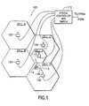
- FIG. 1 illustrates a block diagram of a telecommunications system 100 constructed according to an embodiment of the present invention.
- System 100 comprises mobile station 114 and, an infrastructure comprising system controller and switch 112 and base stations 102,104,106,108 and 110.
- a subscriber who subscribes to service provided by the operator of cellular system 100 may use the mobile station 114 to make and receive phone calls over a radio interface, such as is shown by radio interface 118 between mobile station 114 and base station 108, as the subscriber moves throughout the coverage area of cellular system 100.
- Each of base stations 102, 104, 106, 108 and 110 provide coverage over a separate area of system 100, shown as cell A, cell B, cell C, cell D and cell E, respectively in FIG. 1.
- Base stations 102, 104, 106, 108 and 110 are connected to system controller and switch 112 as in a conventional cellular system.
- System controller and switch 112 is connected to a public switched telephone network to allow subscribers of cellular system 100 to make and receive phone calls from the landline public network.
- Cell A, cell B, cell C and cell D are shown to be of about the same size, and may be the size of what is commonly called a "micro cell” or a cell of about 500 meters in width.
- a micro cell of system 100 may require a maximum mobile station transmission power level of 200 mw.
- Cell E of system 100 is shown to be contained within the coverage area of cell C, and may be the size of what is commonly called a "pico cell" or, a cell of about 100 meters in width.
- a pico cell of system 100 may require a maximum mobile station transmission power level of 20 mw.
- cellular system 100 may operate according to the Telecommunications Industry Association/Electronic Industry Association(TIA/EIA) IS-95 standard for code division multiple access(CDMA) cellular systems, with the transmission power levels within cell E scaled down for pico cell operation.
- TIA/EIA Telecommunications Industry Association/Electronic Industry Association
- CDMA code division multiple access
- Mobile station 114 comprises antenna 200, duplexer 202, transmit power amplifier 204, analog receiver 206, transmit power controller 208, searcher receiver 210, digital data receiver 212, digital data receiver 214, diversity combiner/decoder 216, control processor 218, user digital vocoder 220, transmit modulator 222 and user interface 224.
- Mobile station 114 may function as a conventional CDMA mobile station in functions other than the handoff power control function.
- Mobile station 114 includes modifications that implement the handoff power control of the present invention.
- Antenna 200 is coupled to analog receiver 206 through duplexer 202. Signals received at antenna 200 are input to analog receiver 206 through duplexer 202. The received signals are converted to an IF frequency and then filtered and digitized in analog receiver 206, for input to digital data receiver 212, digital data receiver 214 and searcher receiver 210.
- the digitized IF signal input to digital data receiver 212, digital data receiver 214 and searcher receiver 210 may include signals from many ongoing calls together with the pilot carriers transmitted by the base station of the cell site in which the mobile station is currently located, plus the pilot carriers transmitted by the base stations in all neighboring cell sites.
- Digital data receiver 212 and digital data receiver 214 perform correlation on the IF signal with a PN sequence of a desired received signal.
- the output of digital data receivers 212 and 214 is a sequence of encoded data signals from two independent paths.
- Searcher receiver 210 scans the time domain around the nominal time of a received pilot signal of a base station for other multi-path pilot signals from the same base station and for other signals transmitted from different base stations.
- Searcher receiver 210 measures the strength of any desired waveform at times other than the nominal time.
- Searcher receiver 210 generates signals to control processor 218 indicating the strengths of the measured signals.
- the encoded data signals output from digital data receiver 212 and digital data receiver 214 are input to diversity combiner/decoder 216.
- diversity combiner/decoder 216 the encoded data signals are aligned and combined, and the resultant data signal is then decoded using error correction and input to digital vocoder 220.
- Digital vocoder 220 then outputs information signals to the user interface 224.
- User interface may be a handset with a keypad, or another type of user interface such as a laptop computer monitor and keyboard.
- a signal received at user interface 224 is input to user digital vocoder 220 in digital form, as for example data or voice that has been converted to digital form at user interface 224.
- digital vocoder 220 the signal is encoded and output to transmit modulator 222.
- Transmit modulator 222 Walsh encodes the signal and, then modulates the Walsh encoded signal onto a PN carrier signal, with the PN carrier sequence being the PN carrier sequence of the CDMA channel to which the mobile station is assigned.
- the PN carrier information is transmitted to mobile station 114 from the system 100 and is transferred to control processor 218 from digital data receivers 212 and 214 after being received from the system. Control processor 218 sends the PN carrier information to transmit modulator 222.
- the PN modulated signal is then output from transmit modulator 222 to transmit power control 208.
- Transmit power control 208 sets the level of the transmission power of mobile station 114 according to commands received from control processor 218.
- the power control commands may be generated by control processor 218 according to commands received from the system or may be generated by software of control processor 218, according to predetermined criteria, in response to data received from the system through digital data receivers 212 and 214.
- the modulated signal is then output from transmit power control 208 to transmit power amplifier 204 where the signal is amplified and converted to an RF transmission frequency signal.
- the RF frequency signal is then output from power amplifier 204 to duplexer 202 and is transmitted from antenna 200.
- Base station 110 includes a first receiver section 332, a second receiver section 334, control processor 322, diversity combiner/decoder 324, transmit power controller 326, digital link 328, transmit modulator 330, control channel transmitter/modulator 320, transmit power amplifier 310, and antenna 304.
- First receiver section 332 comprises antenna 300, analog receiver 306, searcher receiver 312 and digital data receiver 314.
- Second receiver section 334 comprises antenna 302, analog receiver 308, searcher receiver 316 and digital data receiver 318.
- First receiver section 332 and second receiver section 334 provide space diversity for a single signal that may be received at both of antennas 300 and 302.
- the signals received at antenna 300 are input to analog receiver 306 where the signal is filtered, converted to an IF frequency and, digitized to generate a digital signal.
- the digital signal is then output from analog receiver 306 to searcher receiver 312 and digital data receiver 314.
- Searcher receiver 312 scans the time domain around the received signal to verify that digital data receiver 314 tracks the correct signal.
- Control processor 322 generates the control signals for digital data receiver 314 according to a signal received from the searcher receiver 312, so that the correct signal is received at digital data receiver 314.
- Digital data receiver 314 generates the proper PN sequence necessary to decode the digital signal received from analog receiver 306 and generates weighted output symbols for input to diversity combiner/decoder 324.
- Antenna 302, analog receiver 308, searcher receiver 316 and digital data receiver 318 of section receiver section 334 function identically to the components of first receiver section 332 to generate a second set of weighted output symbols.
- the weighted symbols from digital data receiver 312 and digital data receiver 318 are then combined and decoded in diversity combiner/decoder 324 to generate received digital data which is then output through digital link 328 to system controller and switch 112 of FIG. 1.
- Base station 100 When data received from system controller and switch 112 is to be transmitted from base station 110 on a traffic channel, the data is received at digital link 328 over I/O 336 and sent to transmit modulator 330. Transmit modulator 330 then modulates the data using the appropriate Walsh function assigned to the mobile station to which the base station is transmitting. The Walsh modulated data is then spread by a voice channel PN sequence having the appropriate time shift and input to transmit power controller 326. Transmit power control 326 controls the transmission power in response to control signals received form control processor 322. The power control commands may be generated by software in control processor 322. The signal output from power controller 326 is input to transmit power amplifier 310, and is then transmitted from antenna 304. Base station 100 may have multiple transmit modulator and transmit power controllers for transmitting to multiple mobile stations.
- FIGs. 4 and 5 therein are flow diagrams illustrating process steps performed by a mobile station and target base station, respectively, according to an embodiment of the present invention.
- the output power of a mobile station is adjusted at handoff according to the estimated power loss between the mobile station and the target base station of the handoff.
- the estimated power loss is based on handoff channel measurements made at the mobile station.
- FIGs. 4 and 5 can be explained with reference to FIGs. 1 - 3 and an exemplary handoff of mobile station 114 from cell D to cell E.
- searcher receiver 210 of mobile station 114 measures the received signal strengths on the system pilot channels in the handoff candidate set and provides signal strength measurement results to control processor 218.
- the handoff candidate set contains the pilots of system 100 that are received at a sufficient strength to indicate that they are handoff candidates and in this example includes the pilot channel of cell E or base station 110.
- the candidate pilot channel from base station 110 will be received at a signal strength level that is a predetermined margin greater than the signal strength level received on the pilot channel of base station 108.
- control processor 218 generates a measurement message indicating the measurement results and the PN offset of the measured candidate pilot of base station 110.
- the process begins at step 402 of FIG. 4 as the measurement message generated in control processor 218 is transmitted from mobile station 114 to the current base station 108.
- the process moves to the wait state of step 404 and mobile station 114 waits for a response from base station 108.
- mobile station 114 is in the wait state of step 404 of FIG. 4, the process moves to step 502 of FIG. 5 as base station 108 receives the measurement message transmitted from mobile station 114.
- base station 108 sends a handoff notification message to base station 110 through system controller and switch 112.
- Control processor 322 receives the handoff notification message through digital link 328 and determines that a free traffic channel exists for mobile station 114.
- control processor 322 then generates an acceptance message that is returned to base station 108 through digital link 328 and system controller and switch 112.
- base station 108 sends a PT(r) value, where PT(r) is the received power level of the pilot of base station 110, to base station 110 through system controller and switch 112 and the PT(r) value is sent to control processor 322 through digital link 328.
- control processor 322 calculates an initial transmission power data for mobile station 114.
- control processor 322 may first calculate the pathloss (PATHLOSS), between mobile station 114 and base station 108, by subtracting PT(r) from the transmission power level PT(t) of the base station 110.
- PATHLOSS pathloss
- Control processor 322 may then calculate an estimated transmission power level PM(t) for mobile station 114 by adding the pathloss to the level at which base station 108 desires to receive the signal from mobile station 114.
- PM(t) When PM(t) is known, it may be used to calculate power control data to be sent to mobile station 114.
- PM(t) may be used, for example, to further calculate a power adjustment value (PAV) to be added to an IS-95 extended handoff direction message having additional fields along with the NOM_PWR value.
- PAV power adjustment value
- the power adjustment value may be used to modify the open and closed loop power control equations used by mobile station 114. In this way the range of adjustments allowed by changing the NOM_PWR value is extended to a range that may be necessary for inter-tier handoffs.
- the NOM_PWR value and the PAV value may then be each set to sum to the necessary adjustment.
- the use of power control data in the extended handoff direction message has an advantage in that the existing IS-95 air interface could be used, and minimum modifications would be required to be made to mobile station software.
- the PAV value is then sent from base station 108 to base station 110.
- the control processor of base station 110 then formats an extended handoff direction message containing additional fields including the PAV value and transmits the extended handoff direction message to mobile station 114.
- the PAV value may be included in place of the reserved field of the extended handoff direction message.
- step 408 control processor 218 of mobile station 114 reads the PAV data contained in the extended handoff direction message.
- control processor 218 generates a message to transmit power controller 208 directing transmit power control 208 to adjust the initial transmission power of the mobile station on the assigned traffic channel at handoff to the level calculated from the NOM_PWR and PAV values by control processor 218.
- step 412 transmit power amplifier 204 is powered on and mobile station 114 begins transmitting on the assigned reverse traffic channel of base station 108 at the initial transmission power level.
- the calculation of the initial mobile station transmission power on the assigned traffic channel of the target base station may also be performed in the mobile station 114.
- the transmission power level PT(t) of base station 108 on the pilot channel and the power level PM(r) at which it was desired to receive the signal from mobile station 114 are transmitted from the target base station 110 to mobile station 114 through the current base station 108 in place of the mobile station power control data (PAV).
- PAV mobile station power control data
- the PT(t) and PM(r) values could be transmitted from target base station 110 directly to mobile station 114 on the pilot channel of target base station 110.
- control processor 218 of mobile station 114 calculates the pathloss (PATHLOSS) between mobile station 114 and base station 108 by subtracting PT(r) from PT(t). Control processor 218 may then calculate an estimated initial transmission power level PM(t) by adding PATHLOSS to the level at which base station 108 desires to receive the signal from mobile station 114 (PM(r)). The initial transmission power for mobile station 114 may be set in transmit power control 208 by appropriate commands sent from control processor 218. In this alternative it would also be possible to use PM(t) to calculate a NOM_PWR value to be used in the open and closed loop power control processes after handoff. NOM_PWR would then not have to be estimated by the target base station.
- PATHLOSS pathloss
- base station power classes are defined for a cellular system.
- the base stations of different size cells having differing mobile station transmission power requirements are each assigned to one of a plurality of power classes of the system.
- the power classes may be defined so that each includes cells having mobile station transmission power requirements within a certain range. This may be done according to cell size. For example, in system 100 of FIG. 1 all of the micro sized cells, Cell A, Cell B, Cell C and Cell D, may be assigned to a first power class and, all pico sized cells, including Cell E, may be assigned to a second power class.
- a mobile station When a mobile station is involved in a handoff it can then adjust its initial output power on the newly assigned traffic channel according to the power class of the target base station of the handoff.
- FIG. 6 therein is shown a flow diagram illustrating process steps performed by a mobile station 114 according to the alternative embodiment of the present invention.
- FIG. 6 can be explained with reference to FIGs. 1 - 3 and an exemplary handoff of mobile station 114 from cell D to cell E.
- cell D is assigned to a first power class
- cell E is assigned to a second power class.
- searcher receiver 210 of mobile station 114 measures the received signal strengths on the system pilot channels of the handoff candidate set and provides signal strength measurement results to control processor 218.
- the signal strength measurements identify each of the pilot channels by the PN offset of the pilot channel.
- the handoff candidates set contains the pilots of system 100 received at a sufficient strength to indicate that they are handoff candidates, and includes the pilot of cell E or base station 110.
- the signal of the pilot from base station 110 will be received at a signal strength level that is a predetermined margin greater than the signal strength level received on the pilot of base station 108.
- control processor 218 generates a measurement message indicating the measurement results and the PN offset (identity) of the measured candidate pilot channel.
- the process begins at step 602 of FIG. 6 as the measurement message generated in control processor 218 is transmitted from mobile station 114 to the current base station 108.
- the process moves to the wait state of step 604 where mobile station 114 waits for a response from base station 108.
- process steps necessary for handoff are performed within the infrastructure of system 100.
- this may be any procedure that is compatible with the IS-95 system standard in which a traffic channel of base station 110 is assigned for the handoff of mobile station 114 and a handoff direction message, including channel assignment data, is sent from base station 108 to mobile station 114.
- the handoff direction message is received by mobile station 114.
- the handoff direction message is received by mobile station 114.
- the message is transferred through receiver sections 332 and 334 to control processor 218 of mobile station 114.
- Control processor 218 determines the power class of target base station 110 from the channel assignment data included in the handoff direction message.
- Control processor 218 may determine the power class by comparing the PN offset of the traffic channel assigned in the handoff direction message with data stored in a memory of control processor 218. The data may indicate the range of offsets for a particular power class, or may indicate directly which PN offsets for the system are contained in each power class.
- control processor 218 determines whether the power class of target base station 110 is different from the power class of current base station 108. If the power class of target base station 110 is different from the power class of current base station 108, the handoff is an inter-tier handoff and the process moves to step 616. In this particular example the handoff is an inter-tier handoff so the process would move to step 616.
- control processor 218 generates control commands to transmit power controller 208 that set the output transmission power for mobile station 114 on the newly assigned traffic channel.
- Control processor 218 may adjust the output transmission power by adjusting the constant -73 up or down, depending on the differences between the power classes, in the mobile station power control equation. For example, in the example shown in FIG.
- the NOM_PWR value transmitted in the extended handoff direction message during hard handoff may also be adjusted taking into account the power class of a target base station.
- the NOM_PWR level of base stations of the power class of base station 110 could be set to provide a initial transmission power when added with the constant -63 that is acceptable for base stations of that class.
- the use of both the modified constant and NOM_PWR provides more range than is provided with only NOM_PWR.
- step 614 the mobile station begins transmission on the new traffic channel and the handoff power control process ends and moves to step 618.
- control processor 218 If, however, at step 610. it is determined that the power class of target base station 110 is not different from the power class of current base station 108, the process moves to step 612. At step 612, control processor 218 generates control commands to transmit power controller 208 that set the output transmission power for mobile station 114 on the newly assigned traffic channel.
- base station identification fields(base station ID) maybe assigned throughout the system, so that a base station's power class may be determined from the base station's ID.
- Mobile stations may then be programmed to recognize the power class of a base station from a base station ID that is received, for example, over a pilot channel or in a handoff confirmation message along with channel assignment information.
- the mobile station may then adjust initial transmissions on the assigned traffic channel for the base station power class.
- This alternative has application in any type of cellular system, analog, TDMA or CDMA, in which an inter-tier handoff could occur.
Description
- This invention relates to handoff in cellular telecommunications systems and, more particularly to an apparatus and method for controlling the transmission power of a mobile station during handoff of a call between base stations of a cellular system.
- In the field of cellular telecommunications, efforts have recently been directed towards developing Code Division Multiple Access(CDMA) type systems. In a CDMA type system multiple users, each using a channel identified by a uniquely assigned digital code, simultaneously communicate with the system while sharing the same wideband frequency spectrum.
- CDMA provides several advantages over conventional frequency division multiple access (FDMA) or time division multiple access (TDMA) systems. In FDMA systems users are assigned a unique frequency for each of mobile to base (uplink or reverse link) and base to mobile (downlink or forward link) communications. In TDMA systems, users are each assigned a unique frequency, for the uplink and downlink, and a unique time period in which to transmit or receive on that frequency. These FDMA and TDMA systems require planning for allocation of channel frequencies and/or time periods on these frequencies to mobile stations and base stations. In a CDMA system, however, frequency and time period assignment planning for mobile stations and the base stations of cells is not necessary, as in FDMA and TDMA systems, because all CDMA base stations share the entire downlink frequency spectrum, and all mobiles share the entire uplink frequency spectrum. The fact that the wideband frequency spectrum is shared by all uplink or downlink users in CDMA also increases capacity, since the number of users that can be multiplexed simultaneously is only limited by the number of digital codes available to identify the unique communications channels of the system, and by the total interference caused by the other users sharing the same spectrum, and not by the number of radio frequency channels available. Additionally, since the energy of the transmitted signals are spread over the wide band uplink or downlink frequency band, selective frequency fading does not affect the entire CDMA signal. Path diversity is also provided in a CDMA system. If multiple propagation paths exist, they can be separated as long as the differences in paths delays exceeds 1/BW, where BW equals the bandwidth of the transmission link.
- In a CDMA cellular system the transmission power levels of mobile stations become important. In CDMA, the signals from many different mobile stations are received at the same frequency simultaneously at a base station. Because of the nature of CDMA demodulation, it is necessary that the signal received at the base station from each mobile station be as close as possible to a single level so that the signal from one mobile station does not overwhelm the signal from another mobile station (near-far problem). In a CDMA cellular system a power control process may be used to control each mobile station's transmission power level so that the signal level received at the base station from each mobile station is as close as possible to a single predetermined level. Additionally, the power control process may also be used to assure that the received signal levels at the base station are of an adequate level, so that calls are not dropped. One example of a CDMA mobile station power control scheme is the power control used by systems specified in the Telecommunications Industry Association/ Electronic Industries Association (TIA/EIA) IS-95 standard. Another related CDMA mobile station power control scheme is the power control used by systems specified in the ANSI-008 standard, which is the personal communications systems (PCS) 1900 Mhz version of IS-95.
- In the IS-95 power control process, a mobile station first adjusts its transmission power level using an access channel assigned to a base station through which the mobile station is attempting to gain access to the system. To gain access the mobile station follows an open loop power control process that involves transmitting access probe transmissions at a relatively low power level on the access channel and gradually increasing the level of subsequent access probe transmissions, in access probe correction increments set by the system, until a response is obtained from the system and the mobile station gains access to the system. The transmission power of each access probe transmission on the access channel is given by the equation:
- The values NOM_PWR and INIT_PWR are system parameters having values assigned by the system. The mean input power is the power level of the reverse link access channel signal as received at the mobile station.
- The ANSI-008 standard equation is similar, but because of the frequency difference, has a constant equal to 76 instead of 73, and also includes an additional value that is added to increase the range of NOM_PWR, the additional value being defined as 16*NOM_PWR_EXT, which is a system parameter. IS-95 could also be modified to include a similar value.
- Once the mobile station gains access to the system, it waits in an idle mode until a call is initiated from either the mobile station to the base station, or from the base station to the mobile station. A reverse traffic channel and a forward traffic channel are then assigned for the call. When transmitting on the IS-95 reverse traffic channel, the mobile station initializes at the level set on the access channel by the open loop process defined by equation (1). Once the reverse traffic channel transmission power level is initialized and the call begins, the system and mobile station then also begin a closed loop power control process. The closed loop power control process allows the signal level received at the base station from each mobile station transmitting on a reverse traffic channel to be set as close as possible to a single predetermined level. In the closed loop power control process the base station transmits closed loop power control corrections in the form of power control bits to the mobile station in a power control subchannel that is included in the forward traffic channel. A single power control bit is transmitted in the power control subchannel every 1.25ms. A "one" bit transmitted in the power control subchannel indicates that the mobile station should increase its transmission power 1 db, while a "zero" bit indicates that the mobile station should decrease its transmission power 1db. Each time a valid control bit is received at the mobile station in the power control subchannel, the mobile station adjusts its output power level up or down in an increment of 1db. The mobile station is capable of adjusting the transmission power within a range of "24 db around the level set by the open loop power control process on the access channel and, as the call is ongoing, the transmission power of the mobile station on the reverse traffic channel is adjusted so that a desired power level is reached and maintained. The mobile station also simultaneously continues the open loop power control process, this time using the forward traffic channel. In the open loop process the mean input power received on the reverse traffic channel is the determining value. When involved in the call, the inputs that effect changes in the mobile station's transmission power are the mean input power as received from the base station on the forward traffic channel and, the closed loop power corrections indicated by the power control bits received on the forward power control channel. During a call, the mobile station output power level on the reverse traffic channel is given by the equation:
- As for equation 1, the ANSI-008 standard equation is similar, but because of the frequency difference, has a constant equal to 76 instead of 73, and also includes an additional value that is added to increase the range of NOM_PWR, the additional value defined as 16*NOM_PWR_EXT, which is a system parameter.
- A handoff of the call from one base station to another base station may occur as the mobile station moves throughout the system. In a CDMA system two types of handoff are possible. A soft handoff occurs when the mobile station commences communications with the new base station without interrupting communications with the old base station. Soft handoff can only be used between CDMA traffic channels having identical channel frequency assignments. A CDMA to CDMA hard handoff occurs when the mobile station is transitioned between two disjoint sets of base stations, different frequency assignments, or different traffic channel frame offsets.
- During soft handoff of a call, the system continues to use the open loop power control process to adjust the transmission power of the mobile station on the reverse traffic channel as the mobile switches to the traffic channels of the new base station. During CDMA to CDMA hard handoff a value of a nominal power (NOM_PWR) setting for the target cell is transmitted to the mobile station in a handoff message. The nominal power(NOM_PWR) setting is then used to set an initial power transmission level on the traffic channel of the new base station. When the mobile station begins transmitting on the new reverse traffic channel, open and closed loop power control then take over so that the transmissions continue at the correct level.
- In a CDMA system having cells of different sizes and base stations with different size transmitters, the base station in a particular cell may have a different desired received signal strength for signals received from mobile stations, as compared to another cell's base station's desired received signal strength for signals received from mobile stations. If this difference exists between neighboring cells, a problem could occur during handoff of a call between the neighboring cells. If the handoff is from a higher power cell to a lower power cell, there could be a potential near-far problem among the mobile stations in the new cell. The mobile station involved in the call handoff may initially be at a power level much greater than other mobile stations in the new cell. The signal from the mobile station involved in the call handoff may then overwhelm the signals from the other mobile stations at the base station causing a near far problem. If the handoff is from a lower power cell to a higher power cell, there could be a potential dropped call problem. The mobile station involved in the call handoff may initially be at a power level much lower than other mobile stations in the new cell. The signal strength received at the new base station from the mobile station in call handoff may not be adequate to maintain the connection on the reverse link, and a dropped call could occur in this situation.
- For the IS-95 type hard handoff, the power control process used may not be adequate to avoid problems in call handoff between cells of different sizes. Again, because handoff occurs at the threshold where the received signal level on the measurement channel of the current base station is slightly greater than the received signal level on the measurement channel of the new base station, the variable of the mean input power used in equations (1) will not cause a significant change in mobile station transmission power. In IS-95 the transmission power level of the mobile station is adjusted at hard handoff by the new base station transmitting a new NOM_PWR value to the mobile station. The NOM_PWR value is typically an estimated value, set to adjust the mobile station transmission power level to an appropriate initial level in the target cell. The new NOM_PWR value is then used in the mobile station to calculate a new mean output power, as given by equation (1) above for the initial transmission of the mobile station on the reverse traffic channel after handoff. In this process the range of the value of NOM_PWR is from -8dB to 7dB. In the ANSI-008 standard the value 16* NOM_PWR_EXT is used along with NOM_PWR in equation 1, so that the range is from -24 dB to 7 dB. In either system, if the mobile station transmission power level is needed to be adjusted beyond what the range allows, a dropped call or near far problem could occur.
- EP-A-0667726 describes a mobile communication system in which, at time of handover from a first base station have a large cellular radius to a second base station having a smaller cellular radius, the transmission power of the mobile station can be reduced. A base station control means informs the second base station of the presence of the mobile station and connect a reverse link of the mobile station to the second base station before connecting a forward link of the mobile. The base station control means, the mobile station and the first and second base stations form a closed loop for effecting closed loop control of the mobile station so as to suppress the output power of the mobile station. However, the system may still suffer from the near-far problem when the reverse link is connected and does not address the dropped call problem
- The present invention seeks to ameliorate near-far and dropped call problems.
- According to the present invention there is provided, in a telecommunication system having a mobile station and an infrastructure including a plurality of base stations, method of controlling the transmission power of the mobile station during the hand off a call between a first base stationand a second base station, the method comprising transmitting a first message from the mobile station to the infrastructure, the first message including a received power measurement made on a measurement channel of the second base station, determining, in the infrastructure, a first parameter from the received power measurement, the transmission power of the second base station on the measurement channel and a power level at which a signal from the mobile station is received at the second base station, transmitting a second message from the infrastructure to the mobile station, the second message including the first parameter, determining, in the mobile station, a transmit power level from the first parameter and Transmitting from the mobile station to the second base station on a traffic channel at the transmit power level. This can reduce the potential for dropped calls or the occurrences of near-far problems during handoff between base stations of different size cells, where the different size cells require mobile stations to transmit at different power levels, depending on the power size.
- Transmitting the first message may comprise transmitting a first message from the mobile station to the first base station and determining a first parameter may comprise transmitting a third message from the first base station to the second base stations, the third message including the received power measurement and determining, at the base station a parameter for the received power measurement, a first power level and a second power level. The first power level being the transmission power of the second base station on the measurement channel and the second power level being a power level at which a signal from the mobile station is received at the second base station.
- Transmitting from the infrastructure to the mobile station may comprise transmitting a fourth message from the second base to the first base station, the fourth message including the first parameter and transmitted a fifth message from the first base station to the mobile station, the fifth message including the first parameter. Transmitting from the infrastructure to the mobile station may comprise transmitting a fourth message from the second base station to the mobile station, the fourth message transmitted on an end face and including a first parameter. The first base station and the second base station may operate at substantially different power levels. The system may comprise a system operating according to the IS-95 system standard.
- According to the present invention there is also provided an apparatus for controlling the transmission power of a mobile station during hand off of a call between a first base station and a second base, the apparatus comprising a first transmitter for transmitting a first message from the mobile station to the infrastructure, the first message including a received power measurement made on a measurement channel of the second base station, a first determiner means for determining, in the infrastructure, a first parameter from the received power measurement, the transmission power of the second base station on the measurement channel and the power level at which a signal from the mobile station is to be received at the second base station, a second transmitter means for transmitting a second message from the infrastructure to the mobile station, the second message including the first parameter determining by the determiner means and a second determiner means for determining, in the mobile station, a transmit power level from the first parameter wherein the first transmitter means transmits from the mobile station to the seconds base station on a traffic channel at the transmit power level.
- According to the present invention there is further provided a telecommunication system comprising infrastructure including first and second base stations and processing means, wherein the first base station is configured to receive a first message from a mobile station, the first message including a received power measure made on the measurement channel of the second base station, the processing means is configured to determine a first parameter from the received power measurement, the transmission power of the second base station on the measurement channel and the power level at which a signat. from the mobile terminal is to be received at the second base station and the first or second base station is configured to transmit a second message to the mobile terminal, the second message including the first parameter for permitting the mobile station to determine in a predetermined manner a transmit power level to the second base station.
- Embodiments of the present invention will now be described by way of example with reference to the accompany drawings in which:
- FIG. 1 illustrates a block diagram of a telecommunications system constructed according to an embodiment of the invention;
- FIG. 2 is a block diagram of portions of a CDMA mobile station that is constructed and operated according to an embodiment of the present invention;
- FIG. 3 is a block diagram of portions of a CDMA base station that is constructed and operated according to an embodiment of the present invention;
- FIG. 4 is a flow diagram illustrating handoff power control process steps performed by the mobile station of FIG. 2 according to an embodiment of the present invention;
- FIG. 5 is a flow diagram illustrating handoff power control process steps performed by the base station of FIG. 3 according to an embodiment of to the present invention; and
- FIG. 6 is a flow diagram illustrating handoff power control process steps performed by the mobile station of FIG. 2 according to an alternative embodiment of the present invention.
-
- FIG. 1 illustrates a block diagram of a
telecommunications system 100 constructed according to an embodiment of the present invention.System 100 comprisesmobile station 114 and, an infrastructure comprising system controller and switch 112 and base stations 102,104,106,108 and 110. A subscriber who subscribes to service provided by the operator ofcellular system 100 may use themobile station 114 to make and receive phone calls over a radio interface, such as is shown byradio interface 118 betweenmobile station 114 andbase station 108, as the subscriber moves throughout the coverage area ofcellular system 100. Each ofbase stations system 100, shown as cell A, cell B, cell C, cell D and cell E, respectively in FIG. 1.Base stations cellular system 100 to make and receive phone calls from the landline public network. Cell A, cell B, cell C and cell D are shown to be of about the same size, and may be the size of what is commonly called a "micro cell" or a cell of about 500 meters in width. A micro cell ofsystem 100 may require a maximum mobile station transmission power level of 200 mw. Cell E ofsystem 100 is shown to be contained within the coverage area of cell C, and may be the size of what is commonly called a "pico cell" or, a cell of about 100 meters in width. A pico cell ofsystem 100 may require a maximum mobile station transmission power level of 20 mw. In the embodiment of FIG. 1,cellular system 100 may operate according to the Telecommunications Industry Association/Electronic Industry Association(TIA/EIA) IS-95 standard for code division multiple access(CDMA) cellular systems, with the transmission power levels within cell E scaled down for pico cell operation. - Referring now to FIG. 2, therein is a block diagram of portions of
mobile station 114 of the embodiment of the invention shown in FIG. 1.Mobile station 114 comprisesantenna 200,duplexer 202, transmitpower amplifier 204,analog receiver 206, transmitpower controller 208,searcher receiver 210,digital data receiver 212,digital data receiver 214, diversity combiner/decoder 216,control processor 218, userdigital vocoder 220, transmit modulator 222 anduser interface 224.Mobile station 114 may function as a conventional CDMA mobile station in functions other than the handoff power control function.Mobile station 114 includes modifications that implement the handoff power control of the present invention. -
Antenna 200 is coupled toanalog receiver 206 throughduplexer 202. Signals received atantenna 200 are input toanalog receiver 206 throughduplexer 202. The received signals are converted to an IF frequency and then filtered and digitized inanalog receiver 206, for input todigital data receiver 212,digital data receiver 214 andsearcher receiver 210. The digitized IF signal input todigital data receiver 212,digital data receiver 214 andsearcher receiver 210 may include signals from many ongoing calls together with the pilot carriers transmitted by the base station of the cell site in which the mobile station is currently located, plus the pilot carriers transmitted by the base stations in all neighboring cell sites.Digital data receiver 212 anddigital data receiver 214 perform correlation on the IF signal with a PN sequence of a desired received signal. The output ofdigital data receivers Searcher receiver 210 scans the time domain around the nominal time of a received pilot signal of a base station for other multi-path pilot signals from the same base station and for other signals transmitted from different base stations.Searcher receiver 210 measures the strength of any desired waveform at times other than the nominal time.Searcher receiver 210 generates signals to controlprocessor 218 indicating the strengths of the measured signals. - The encoded data signals output from
digital data receiver 212 anddigital data receiver 214 are input to diversity combiner/decoder 216. In diversity combiner/decoder 216 the encoded data signals are aligned and combined, and the resultant data signal is then decoded using error correction and input todigital vocoder 220.Digital vocoder 220 then outputs information signals to theuser interface 224. User interface may be a handset with a keypad, or another type of user interface such as a laptop computer monitor and keyboard. - For transmission of signals from
mobile station 114, a signal received atuser interface 224 is input to userdigital vocoder 220 in digital form, as for example data or voice that has been converted to digital form atuser interface 224. Indigital vocoder 220 the signal is encoded and output to transmit modulator 222. Transmit modulator 222 Walsh encodes the signal and, then modulates the Walsh encoded signal onto a PN carrier signal, with the PN carrier sequence being the PN carrier sequence of the CDMA channel to which the mobile station is assigned. The PN carrier information is transmitted tomobile station 114 from thesystem 100 and is transferred to controlprocessor 218 fromdigital data receivers Control processor 218 sends the PN carrier information to transmit modulator 222. The PN modulated signal is then output from transmit modulator 222 to transmitpower control 208. Transmitpower control 208 sets the level of the transmission power ofmobile station 114 according to commands received fromcontrol processor 218. The power control commands may be generated bycontrol processor 218 according to commands received from the system or may be generated by software ofcontrol processor 218, according to predetermined criteria, in response to data received from the system throughdigital data receivers - The modulated signal is then output from transmit
power control 208 to transmitpower amplifier 204 where the signal is amplified and converted to an RF transmission frequency signal. The RF frequency signal is then output frompower amplifier 204 toduplexer 202 and is transmitted fromantenna 200. - Referring now to FIG. 3, therein is a block diagram of portions of a
base station 110 of the embodiment of the invention shown in FIG. 1. The block diagrams of any of theother base stations base station 110.Base station 110 includes afirst receiver section 332, asecond receiver section 334,control processor 322, diversity combiner/decoder 324, transmitpower controller 326,digital link 328, transmitmodulator 330, control channel transmitter/modulator 320, transmitpower amplifier 310, andantenna 304.First receiver section 332 comprisesantenna 300,analog receiver 306,searcher receiver 312 anddigital data receiver 314.Second receiver section 334 comprisesantenna 302,analog receiver 308,searcher receiver 316 anddigital data receiver 318. -
First receiver section 332 andsecond receiver section 334 provide space diversity for a single signal that may be received at both ofantennas antenna 300 are input toanalog receiver 306 where the signal is filtered, converted to an IF frequency and, digitized to generate a digital signal. The digital signal is then output fromanalog receiver 306 tosearcher receiver 312 anddigital data receiver 314.Searcher receiver 312 scans the time domain around the received signal to verify thatdigital data receiver 314 tracks the correct signal.Control processor 322 generates the control signals fordigital data receiver 314 according to a signal received from thesearcher receiver 312, so that the correct signal is received atdigital data receiver 314.Digital data receiver 314 generates the proper PN sequence necessary to decode the digital signal received fromanalog receiver 306 and generates weighted output symbols for input to diversity combiner/decoder 324.Antenna 302,analog receiver 308,searcher receiver 316 anddigital data receiver 318 ofsection receiver section 334 function identically to the components offirst receiver section 332 to generate a second set of weighted output symbols. The weighted symbols fromdigital data receiver 312 anddigital data receiver 318 are then combined and decoded in diversity combiner/decoder 324 to generate received digital data which is then output throughdigital link 328 to system controller and switch 112 of FIG. 1. - When data received from system controller and switch 112 is to be transmitted from
base station 110 on a traffic channel, the data is received atdigital link 328 over I/O 336 and sent to transmitmodulator 330. Transmit modulator 330 then modulates the data using the appropriate Walsh function assigned to the mobile station to which the base station is transmitting. The Walsh modulated data is then spread by a voice channel PN sequence having the appropriate time shift and input to transmitpower controller 326. Transmitpower control 326 controls the transmission power in response to control signals receivedform control processor 322. The power control commands may be generated by software incontrol processor 322. The signal output frompower controller 326 is input to transmitpower amplifier 310, and is then transmitted fromantenna 304.Base station 100 may have multiple transmit modulator and transmit power controllers for transmitting to multiple mobile stations. - In system 100 a pilot channel that may be used for handoff measurements is generated by each base station. The pilot channel generated for each base station of
system 100 is unique, with each pilot channel being identified by the time shift (or phase) of the PN sequence transmitted from the particular base station, rather than by a unique PN sequence. The pilot channel forbase station 110 may be generated in control channel modulator/power control 320 in response to control signals generated bycontrol processor 322. The pilot channel signal may be generated by using a Walsh code sequence of all zeros and, multiplying the Walsh code sequence by the system PN sequence to generate a pilot channel signal having the appropriate phase for thebase station 110. - Referring now to FIGs. 4 and 5, therein are flow diagrams illustrating process steps performed by a mobile station and target base station, respectively, according to an embodiment of the present invention. In this embodiment, the output power of a mobile station is adjusted at handoff according to the estimated power loss between the mobile station and the target base station of the handoff. The estimated power loss is based on handoff channel measurements made at the mobile station. The mobile station=s output power is adjusted, according to the estimated power loss, to within an initial acceptable range. This minimizes dropped calls or near far problems that could occur when handoff is between cells of different sizes. FIGs. 4 and 5 can be explained with reference to FIGs. 1 - 3 and an exemplary handoff of
mobile station 114 from cell D to cell E. - As
mobile station 114 moves within cell D in the direction ofarrow 116 towards cell E,searcher receiver 210 ofmobile station 114 measures the received signal strengths on the system pilot channels in the handoff candidate set and provides signal strength measurement results to controlprocessor 218. The handoff candidate set contains the pilots ofsystem 100 that are received at a sufficient strength to indicate that they are handoff candidates and in this example includes the pilot channel of cell E orbase station 110. Whenmobile station 114 is at a certain location on, or near, the borders of cells D and E , the candidate pilot channel frombase station 110 will be received at a signal strength level that is a predetermined margin greater than the signal strength level received on the pilot channel ofbase station 108. At this point,control processor 218 generates a measurement message indicating the measurement results and the PN offset of the measured candidate pilot ofbase station 110. - The process begins at
step 402 of FIG. 4 as the measurement message generated incontrol processor 218 is transmitted frommobile station 114 to thecurrent base station 108. Next, the process moves to the wait state ofstep 404 andmobile station 114 waits for a response frombase station 108. Whilemobile station 114 is in the wait state ofstep 404 of FIG. 4, the process moves to step 502 of FIG. 5 asbase station 108 receives the measurement message transmitted frommobile station 114. Next, atstep 504base station 108 sends a handoff notification message tobase station 110 through system controller andswitch 112.Control processor 322 receives the handoff notification message throughdigital link 328 and determines that a free traffic channel exists formobile station 114. Atstep 506,control processor 322 then generates an acceptance message that is returned tobase station 108 throughdigital link 328 and system controller andswitch 112. Next, atstep 508,base station 108 sends a PT(r) value, where PT(r) is the received power level of the pilot ofbase station 110, tobase station 110 through system controller and switch 112 and the PT(r) value is sent to controlprocessor 322 throughdigital link 328. Next, atstep 510,control processor 322 calculates an initial transmission power data formobile station 114. Atstep 510,control processor 322 may first calculate the pathloss (PATHLOSS), betweenmobile station 114 andbase station 108, by subtracting PT(r) from the transmission power level PT(t) of thebase station 110.Control processor 322 may then calculate an estimated transmission power level PM(t) formobile station 114 by adding the pathloss to the level at whichbase station 108 desires to receive the signal frommobile station 114. When PM(t) is known, it may be used to calculate power control data to be sent tomobile station 114. PM(t) may be used, for example, to further calculate a power adjustment value (PAV) to be added to an IS-95 extended handoff direction message having additional fields along with the NOM_PWR value. The power adjustment value may be used to modify the open and closed loop power control equations used bymobile station 114. In this way the range of adjustments allowed by changing the NOM_PWR value is extended to a range that may be necessary for inter-tier handoffs. The NOM_PWR value and the PAV value may then be each set to sum to the necessary adjustment. The use of power control data in the extended handoff direction message has an advantage in that the existing IS-95 air interface could be used, and minimum modifications would be required to be made to mobile station software. Next, atstep 512, the PAV value is then sent frombase station 108 tobase station 110. The control processor ofbase station 110 then formats an extended handoff direction message containing additional fields including the PAV value and transmits the extended handoff direction message tomobile station 114. The PAV value may be included in place of the reserved field of the extended handoff direction message. - The process moves to step 406 of FIG. 4, where
mobile station 114 receives the extended handoff direction message frombase station 110. The process then moves to step 408. Atstep 408control processor 218 ofmobile station 114 reads the PAV data contained in the extended handoff direction message. Next, atstep 410,control processor 218 generates a message to transmitpower controller 208 directing transmitpower control 208 to adjust the initial transmission power of the mobile station on the assigned traffic channel at handoff to the level calculated from the NOM_PWR and PAV values bycontrol processor 218.Control processor 218 may calculate the desired initial transmission power for the mobile station by replacing the NOM_PWR and INIT_PWR fields in the mobile station output power control equation to begin transmissions on the new traffic channel so that: - After the initial transmission power for
mobile station 114 is set by transmitpower control 208 the process moves to step 412. Atstep 412, transmitpower amplifier 204 is powered on andmobile station 114 begins transmitting on the assigned reverse traffic channel ofbase station 108 at the initial transmission power level.
As an alternative, the calculation of the initial mobile station transmission power on the assigned traffic channel of the target base station may also be performed in themobile station 114. In this alternative, the transmission power level PT(t) ofbase station 108 on the pilot channel and the power level PM(r) at which it was desired to receive the signal frommobile station 114 are transmitted from thetarget base station 110 tomobile station 114 through thecurrent base station 108 in place of the mobile station power control data (PAV). Alternatively, the PT(t) and PM(r) values could be transmitted fromtarget base station 110 directly tomobile station 114 on the pilot channel oftarget base station 110. - In this
case control processor 218 ofmobile station 114 calculates the pathloss (PATHLOSS) betweenmobile station 114 andbase station 108 by subtracting PT(r) from PT(t).Control processor 218 may then calculate an estimated initial transmission power level PM(t) by adding PATHLOSS to the level at whichbase station 108 desires to receive the signal from mobile station 114 (PM(r)). The initial transmission power formobile station 114 may be set in transmitpower control 208 by appropriate commands sent fromcontrol processor 218. In this alternative it would also be possible to use PM(t) to calculate a NOM_PWR value to be used in the open and closed loop power control processes after handoff. NOM_PWR would then not have to be estimated by the target base station. This NOM_PWR value could be calculated by the equation: - In an alternative embodiment of the invention, base station power classes are defined for a cellular system. In a cellular system according to this embodiment, the base stations of different size cells having differing mobile station transmission power requirements are each assigned to one of a plurality of power classes of the system. The power classes may be defined so that each includes cells having mobile station transmission power requirements within a certain range. This may be done according to cell size. For example, in
system 100 of FIG. 1 all of the micro sized cells, Cell A, Cell B, Cell C and Cell D, may be assigned to a first power class and, all pico sized cells, including Cell E, may be assigned to a second power class. When a mobile station is involved in a handoff it can then adjust its initial output power on the newly assigned traffic channel according to the power class of the target base station of the handoff. - Referring now to FIG. 6, therein is shown a flow diagram illustrating process steps performed by a
mobile station 114 according to the alternative embodiment of the present invention. FIG. 6 can be explained with reference to FIGs. 1 - 3 and an exemplary handoff ofmobile station 114 from cell D to cell E. In this example, cell D is assigned to a first power class and cell E is assigned to a second power class. - As
mobile station 114 moves within cell D in the direction ofarrow 116 towards cell E,searcher receiver 210 ofmobile station 114 measures the received signal strengths on the system pilot channels of the handoff candidate set and provides signal strength measurement results to controlprocessor 218. The signal strength measurements identify each of the pilot channels by the PN offset of the pilot channel. The handoff candidates set contains the pilots ofsystem 100 received at a sufficient strength to indicate that they are handoff candidates, and includes the pilot of cell E orbase station 110. Whenmobile station 114 is at a certain location on or near the borders of cells D and E, the signal of the pilot frombase station 110 will be received at a signal strength level that is a predetermined margin greater than the signal strength level received on the pilot ofbase station 108. At this point,control processor 218 generates a measurement message indicating the measurement results and the PN offset (identity) of the measured candidate pilot channel. - The process begins at
step 602 of FIG. 6 as the measurement message generated incontrol processor 218 is transmitted frommobile station 114 to thecurrent base station 108. Next, the process moves to the wait state ofstep 604 wheremobile station 114 waits for a response frombase station 108. Whilemobile station 114 is in the wait state of 604, process steps necessary for handoff are performed within the infrastructure ofsystem 100. As an example, this may be any procedure that is compatible with the IS-95 system standard in which a traffic channel ofbase station 110 is assigned for the handoff ofmobile station 114 and a handoff direction message, including channel assignment data, is sent frombase station 108 tomobile station 114. When the handoff procedure performed within the system is completed, the handoff direction message is received bymobile station 114. - At
step 606 the handoff direction message is received bymobile station 114. Next, atstep 608, the message is transferred throughreceiver sections processor 218 ofmobile station 114.Control processor 218 then determines the power class oftarget base station 110 from the channel assignment data included in the handoff direction message. -
Control processor 218 may determine the power class by comparing the PN offset of the traffic channel assigned in the handoff direction message with data stored in a memory ofcontrol processor 218. The data may indicate the range of offsets for a particular power class, or may indicate directly which PN offsets for the system are contained in each power class. Next, atstep 610,control processor 218 determines whether the power class oftarget base station 110 is different from the power class ofcurrent base station 108. If the power class oftarget base station 110 is different from the power class ofcurrent base station 108, the handoff is an inter-tier handoff and the process moves to step 616. In this particular example the handoff is an inter-tier handoff so the process would move to step 616. Atstep 616,control processor 218 generates control commands to transmitpower controller 208 that set the output transmission power formobile station 114 on the newly assigned traffic channel.Control processor 218 may adjust the output transmission power by adjusting the constant -73 up or down, depending on the differences between the power classes, in the mobile station power control equation. For example, in the example shown in FIG. 1,target base station 110 is of class 10 dB(200mw/20mw) below the class ofbase station 108, so that for a soft handoff the constant may be reduced by 10 dB: first - The NOM_PWR value transmitted in the extended handoff direction message during hard handoff may also be adjusted taking into account the power class of a target base station. For example, the NOM_PWR level of base stations of the power class of
base station 110 could be set to provide a initial transmission power when added with the constant -63 that is acceptable for base stations of that class. The use of both the modified constant and NOM_PWR provides more range than is provided with only NOM_PWR. - Next, at
step 614, the mobile station begins transmission on the new traffic channel and the handoff power control process ends and moves to step 618. - If, however, at
step 610. it is determined that the power class oftarget base station 110 is not different from the power class ofcurrent base station 108, the process moves to step 612. Atstep 612,control processor 218 generates control commands to transmitpower controller 208 that set the output transmission power formobile station 114 on the newly assigned traffic channel. - As an alternative, base station identification fields(base station ID) maybe assigned throughout the system, so that a base station's power class may be determined from the base station's ID. Mobile stations may then be programmed to recognize the power class of a base station from a base station ID that is received, for example, over a pilot channel or in a handoff confirmation message along with channel assignment information. Upon receiving handoff confirmation from the system the mobile station may then adjust initial transmissions on the assigned traffic channel for the base station power class. This alternative has application in any type of cellular system, analog, TDMA or CDMA, in which an inter-tier handoff could occur.
- While the invention has been particularly shown and described with respect to preferred embodiments thereof, it will be understood by those skilled in the art that changes in form and details may be made therein.
Claims (8)
- A method of controlling in a telecommunications system (100) having a mobile station (114) and an infrastructure including a plurality of base stations (102, 104, 106, 108, 110), the transmission power of the mobile station during handoff of a call between a first base station (108), and a second base station (110), said method comprising the steps of:transmitting a first message from the mobile station (114) to the infrastructure, said first message including a received power measurement made on a measurement channel of the second base station (110);determining, in the infrastructure, a first parameter from said received power measurement, the transmission power of the second base station on said measurement channel, and a power level at which a signal from the mobile station (114) is to be received at the second base station (110);transmitting a second message from the infrastructure to the mobile station(114), said second message including said first parameter;determining, in the mobile station(114), a transmit power level from said first parameter; andtransmitting from the mobile station (114) to the second base station (110) on a traffic channel at said transmit power level
- The method of claim 1, wherein said step of transmitting a first message comprises transmitting a first message from the mobile station (114) to the first base station (108), and said step of determining a first parameter comprises the steps of:transmitting a third message from the first base station (108) to the second base station (110), said third message including said received power measurement; anddetermining, at the second base station (110), a first parameter from said received power measurement, a first power level and a second power level, said first power level being the transmission power of the second base station on said measurement channel and said second power level being a power level at which a signal from the mobile station is to be received at the second base station.
- The method of claim 2, wherein said step of transmitting from the infrastructure to the mobile station (114) comprises the steps of:transmitting a fourth message from the second base station (110) to the first base station (108); said fourth message including said first parameter; andtransmitting a fifth message from the first base station (108) to the mobile station (114), said fifth message including said first parameter.
- The method of claim 2, wherein said step of transmitting from the infrastructure to the mobile station (114) comprises transmitting a fourth message from the second base station (110) to the mobile station (114), said fourth message transmitted on an air interface and including said first parameter.
- The method of any preceding claim, wherein said first base station (108) and said second base station (110) operate at substantially different power levels.
- The method of any preceding claim, wherein the system comprises a system operating according to the IS-95 system standard.
- Apparatus for controlling the transmission power of a mobile station (114) during handoff of a call between a first base station (108) and a second base station (110), said apparatus comprising:a first transmitter means (200, 202, 204, 208, 218) for transmitting a first message from the mobile station to the telecommunications system infrastructure, the infrastructure includes a plurality of base stations (102, 104, 106, 108, 110), said first message including a received power measurement made on a measurement channel of the second base station;a first determiner means (322) for determining, in the infrastructure, a first parameter from said received power measurement, the transmission power of the second base station on said measurement channel, and a power level at which a signal from the mobile station is to be received at the second base station;a second transmitter means (304, 310, 326, 322) for transmitting a second message from the infrastructure to the mobile station, said second message including said first parameter determined by said determiner means; anda second determiner means (218) for determining, in the mobile station, a transmit power level from said first parameter; wherein said first transmitted means transmits from the mobile station to the second base station on a traffic channel at said transmit power level.
- A telecommunications system (100) adapted to control the transmission power of a mobile station during hand off comprising infrastructure including:first and second base stations (108, 110) andprocessing means (108); therein:the first base station (108) is configured to receive a first message from a mobile station (114), the first message including a received power measurement made on a measurement channel of the second base station;the processing means (108) is configured to determine a first parameter from the received power measurement, the transmission power of the second base station on the measurement channel and a power level at which a signal from the mobile terminal is to be received at the second base station; andthe first or second base station (108, 110) is configured to transmit a second message to the mobile terminal, the second message including the first parameter for permitting the mobile station (114) to determine, in a predetermined manner, a transmit power level to the second base station.
Applications Claiming Priority (2)
| Application Number | Priority Date | Filing Date | Title |
|---|---|---|---|
| US869784 | 1997-06-05 | ||
| US08/869,784 US5940743A (en) | 1997-06-05 | 1997-06-05 | Power control of mobile station transmissions during handoff in a cellular system |
Publications (3)
| Publication Number | Publication Date |
|---|---|
| EP0883251A2 EP0883251A2 (en) | 1998-12-09 |
| EP0883251A3 EP0883251A3 (en) | 2002-07-03 |
| EP0883251B1 true EP0883251B1 (en) | 2005-04-13 |
Family
ID=25354261
Family Applications (1)
| Application Number | Title | Priority Date | Filing Date |
|---|---|---|---|
| EP98304471A Expired - Lifetime EP0883251B1 (en) | 1997-06-05 | 1998-06-05 | Power control of mobile station transmission during handoff in a cellular system |
Country Status (3)
| Country | Link |
|---|---|
| US (1) | US5940743A (en) |
| EP (1) | EP0883251B1 (en) |
| DE (1) | DE69829709T2 (en) |
Families Citing this family (93)
| Publication number | Priority date | Publication date | Assignee | Title |
|---|---|---|---|---|
| US5841768A (en) | 1996-06-27 | 1998-11-24 | Interdigital Technology Corporation | Method of controlling initial power ramp-up in CDMA systems by using short codes |
| JPH10117166A (en) * | 1996-10-08 | 1998-05-06 | Nec Ic Microcomput Syst Ltd | Mobile body communication system |
| US5995834A (en) * | 1996-12-24 | 1999-11-30 | At&T Wireless Services, Inc. | Method for controlling channel re-selection from a selected control channel to an alternative control channel |
| US20060280140A9 (en) * | 1997-02-06 | 2006-12-14 | Mahany Ronald L | LOWER POWER WIRELESS BEACONING NETWORK SUPPORTING PROXIMAL FORMATION, SEPARATION AND REFORMATION OF WIRELESS LOCAL AREA NETWORKS (LAN's), AS TERMINALS MOVE IN AND OUT RANGE OF ONE ANOTHER |
| US6393005B1 (en) * | 1997-06-27 | 2002-05-21 | Nec Corporation | Method of controlling transmitting power of a base station in a CDMA mobile communication system |
| US6418320B2 (en) * | 1997-08-12 | 2002-07-09 | Nec Corporation | Mobile station and a method of reducing interference among radio channels in the mobile station |
| US6069881A (en) * | 1997-10-18 | 2000-05-30 | Lucent Technologies, Inc. | Method and apparatus for detecting and dealing with malfunctioning CDMA wireless terminals |
| DE69739331D1 (en) * | 1997-12-10 | 2009-05-07 | Mitsubishi Electric Corp | Transmission power and data rate based communication control method in a mobile radio system |
| US6708041B1 (en) * | 1997-12-15 | 2004-03-16 | Telefonaktiebolaget Lm (Publ) | Base station transmit power control in a CDMA cellular telephone system |
| JP3956479B2 (en) * | 1998-04-27 | 2007-08-08 | ソニー株式会社 | Mobile communication system, mobile station and base station |
| US6163698A (en) * | 1998-05-04 | 2000-12-19 | Motorola | Link setup method for a narrowband cellular communication system |
| KR100264787B1 (en) * | 1998-06-15 | 2000-09-01 | 김영환 | Method for controlling hand-off in mobile communication system |
| US6819937B2 (en) * | 1998-06-30 | 2004-11-16 | Nokia Corporation | Data transmission in a TDMA system |
| US6275478B1 (en) * | 1998-07-10 | 2001-08-14 | Qualcomm Incorporated | Methods and apparatuses for fast power control of signals transmitted on a multiple access channel |
| US6438116B1 (en) * | 1998-07-16 | 2002-08-20 | Telefonaktiebolaget L M Ericsson (Publ) | Adaptive power margin for hard handoffs in code division multiple access based systems |
| JP4131052B2 (en) | 1998-07-17 | 2008-08-13 | ソニー株式会社 | Imaging device |
| US6381230B1 (en) * | 1998-07-28 | 2002-04-30 | Qualcomm Incorporated | Method and system for providing personal base station communications |
| KR20000013025A (en) * | 1998-08-01 | 2000-03-06 | 윤종용 | Forward initial transmitting power control device of telecommunication system and method therefor |
| JP3479935B2 (en) * | 1998-08-19 | 2003-12-15 | 富士通株式会社 | Handover method in CDMA mobile communication, CDMA mobile communication system, base station and mobile station thereof |
| KR100291478B1 (en) * | 1998-09-08 | 2001-06-01 | 윤종용 | Method and system for idle handoff in cellular system |
| US6278879B1 (en) * | 1998-09-22 | 2001-08-21 | Motorola, Inc. | Method for determining a transmit power of a base station in a cellular communication system |
| EP0996304B1 (en) * | 1998-10-19 | 2007-03-14 | Nortel Matra Cellular | Method and apparatus for setting up a connection to a target base station in a cellular or cordless mobile communications system |
| SE522834C2 (en) * | 1998-11-11 | 2004-03-09 | Ericsson Telefon Ab L M | Device, system and method related to radio communication |
| US6512925B1 (en) * | 1998-12-03 | 2003-01-28 | Qualcomm, Incorporated | Method and apparatus for controlling transmission power while in soft handoff |
| US6914889B1 (en) * | 1998-12-08 | 2005-07-05 | Lucent Technologies Inc. | Variable rate forward power control for multichannel applications |
| KR100366799B1 (en) * | 1998-12-26 | 2003-04-07 | 엘지전자 주식회사 | Transmission power control method of mobile communication system |
| US7257404B1 (en) | 1998-12-30 | 2007-08-14 | At&T Corp. | Neighborhood cordless service call handoff |
| JP2001069151A (en) * | 1999-08-26 | 2001-03-16 | Matsushita Electric Ind Co Ltd | Base station device, identifier managing device and identifier assigning method |
| JP3358598B2 (en) | 1999-09-14 | 2002-12-24 | 日本電気株式会社 | Transmission power correction circuit |
| US6628958B1 (en) * | 1999-09-15 | 2003-09-30 | Lucent Technologies Inc. | Method for adjusting the transmit power level during soft handoff in wireless communication systems |
| EP1087630B1 (en) * | 1999-09-24 | 2009-07-15 | Alcatel Lucent | Method for dynamic channel allocation with rearrangement in a TDD/CDMA radio communications system and system therefor |
| US6985466B1 (en) * | 1999-11-09 | 2006-01-10 | Arraycomm, Inc. | Downlink signal processing in CDMA systems utilizing arrays of antennae |
| GB2356771A (en) * | 1999-11-24 | 2001-05-30 | Motorola Ltd | Signal measurement in a second capsule within a cell by a first capsule whilst it is servicing a call |
| AU2001231175A1 (en) * | 2000-01-26 | 2001-08-07 | Vyyo, Ltd. | Quality of service scheduling scheme for a broadband wireless access system |
| US6876834B2 (en) * | 2000-01-26 | 2005-04-05 | Vyyo, Ltd. | Power inserter configuration for wireless modems |
| US6941119B2 (en) * | 2000-01-26 | 2005-09-06 | Vyyo Ltd. | Redundancy scheme for the radio frequency front end of a broadband wireless hub |
| AU2001237988A1 (en) * | 2000-01-26 | 2001-08-07 | Vyyo, Ltd. | Transverter control mechanism for a wireless modem in a broadband wireless access system |
| US7123650B2 (en) * | 2000-01-26 | 2006-10-17 | Vyyo, Inc. | Offset carrier frequency correction in a two-way broadband wireless access system |
| AU2001237971A1 (en) | 2000-01-26 | 2001-08-07 | Vyyo, Ltd. | Space diversity method and system for broadband wireless access |
| WO2001056309A1 (en) * | 2000-01-26 | 2001-08-02 | Vyyo, Ltd. | Distributed processing for optimal qos in a broadband access system |
| US6940833B2 (en) | 2000-01-26 | 2005-09-06 | Vyyo Ltd. | Two-dimensional scheduling scheme for a broadband wireless access system |
| WO2001056179A1 (en) | 2000-01-26 | 2001-08-02 | Vyyo, Ltd. | Programmable phy for broadband wireless access systems |
| KR100387034B1 (en) * | 2000-02-01 | 2003-06-11 | 삼성전자주식회사 | Apparatus and method for scheduling packet data service in wireless communication system |
| AU2001243476A1 (en) | 2000-03-07 | 2001-09-17 | Vyyo, Ltd. | Adaptive downstream modulation scheme for broadband wireless access systems |
| WO2001069824A1 (en) * | 2000-03-14 | 2001-09-20 | Vyyo, Ltd. | Low-complexity beam forming and antenna diversity receiver |
| US6628952B1 (en) * | 2000-04-07 | 2003-09-30 | Nortel Networks Limited | Method of increasing capacity in a fixed wireless access network in which subscribers communicate with base stations via directional antennas |
| US6834192B1 (en) * | 2000-07-03 | 2004-12-21 | Nokia Corporation | Method, and associated apparatus, for effectuating handover of communications in a bluetooth, or other, radio communication system |
| US7567781B2 (en) * | 2001-01-05 | 2009-07-28 | Qualcomm, Incorporated | Method and apparatus for power level adjustment in a wireless communication system |
| US7945266B2 (en) * | 2000-12-05 | 2011-05-17 | Qualcomm Incorporated | Method and apparatus for call recovery in a wireless communication system |
| KR100387059B1 (en) * | 2001-02-06 | 2003-06-12 | 삼성전자주식회사 | Method for using a program in common by use of board id in mobile communication system |
| US6937641B2 (en) * | 2001-02-28 | 2005-08-30 | Golden Bridge Technology, Inc. | Power-controlled random access |
| US7260415B1 (en) * | 2001-05-31 | 2007-08-21 | Sprint Spectrum L.P. | Method and system for location-based power control in wireless communications |
| US20020183086A1 (en) * | 2001-06-04 | 2002-12-05 | Martin Hellmark | Technique for improving open loop power control in spread spectrum telecommunications systems |
| US7065359B2 (en) * | 2001-10-09 | 2006-06-20 | Lucent Technologies Inc. | System and method for switching between base stations in a wireless communications system |
| WO2003077584A1 (en) * | 2002-03-08 | 2003-09-18 | Nokia Corporation | Method and device for controlling the power in an asymmetric soft handover condition |
| JP2003348637A (en) * | 2002-05-23 | 2003-12-05 | Nec Corp | Mobile communication system |
| US6748235B1 (en) * | 2002-11-12 | 2004-06-08 | Interdigital Technology Corporation | Power control during a transmission pause |
| JP4173405B2 (en) * | 2003-05-29 | 2008-10-29 | 京セラ株式会社 | Communication terminal out-of-range determination method, communication terminal |
| KR100541876B1 (en) * | 2003-06-05 | 2006-01-10 | 한국전자통신연구원 | A method for hand over in OFDMA cellular system and an apparatus used therin |
| US7636322B1 (en) | 2005-03-07 | 2009-12-22 | Sprint Spectrum L.P. | Method and system for management of RF access probes based on RF conditions |
| US7848298B2 (en) * | 2005-03-08 | 2010-12-07 | Qualcomm Incorporated | De-coupling forward and reverse link assignment for multi-carrier wireless communication systems |
| US8494531B2 (en) * | 2005-03-25 | 2013-07-23 | Qualcomm Incorporated | System and method for creating a wireless picocell |
| JP4538366B2 (en) * | 2005-03-29 | 2010-09-08 | 株式会社エヌ・ティ・ティ・ドコモ | Transmission rate control method, mobile station and radio base station |
| US20060229073A1 (en) * | 2005-03-31 | 2006-10-12 | Suman Das | Transmitting handoff messages using higher power |
| US8712422B1 (en) | 2005-05-18 | 2014-04-29 | Sprint Spectrum L.P. | Dynamic allocation of access channels based on access channel occupancy in a cellular wireless communication system |
| IL170925A (en) | 2005-09-18 | 2010-12-30 | Alvarion Ltd | Method and device for transmission power control in wireless communications networks |
| US8588837B2 (en) * | 2006-03-15 | 2013-11-19 | Alcatel Lucent | Power control for handoffs between voice over internet protocol and circuit switched calls |
| WO2007133789A2 (en) * | 2006-05-12 | 2007-11-22 | Telsima, Inc. | Customer facing interface power cycling of wireless terminals |
| US20070280377A1 (en) * | 2006-06-02 | 2007-12-06 | Rucki John S | Apparatus and method for controlling the output power of a transmitter using a pilot channel power level |
| US7961641B1 (en) * | 2007-04-27 | 2011-06-14 | Marvell International Ltd. | Initial ranging power control algorithm for WiMAX mobile stations |
| EP3422779B8 (en) * | 2007-08-07 | 2023-11-15 | Malikie Innovations Limited | Method and system for determining access during inter-technologies handoff |
| US20090047962A1 (en) * | 2007-08-14 | 2009-02-19 | Rao Anil M | Transfer-of uplink power control parameters during handovers |
| US20090143044A1 (en) * | 2007-11-30 | 2009-06-04 | Motorola, Inc. | Method and apparatus for operating a wireless communication device in an electromagnetically sensitive environment |
| US8626079B2 (en) * | 2007-12-12 | 2014-01-07 | Electronics And Telecommunications Research Institute | Link adaptation method and apparatus in wireless communication system |
| US8140107B1 (en) | 2008-01-04 | 2012-03-20 | Sprint Spectrum L.P. | Method and system for selective power control of wireless coverage areas |
| US8995559B2 (en) * | 2008-03-28 | 2015-03-31 | Qualcomm Incorporated | Signaling message transmission in a wireless communication network |
| US9276787B2 (en) * | 2008-03-28 | 2016-03-01 | Qualcomm Incorporated | Transmission of signaling messages using beacon signals |
| US9143946B2 (en) | 2008-09-15 | 2015-09-22 | Qualcomm Incorporated | Interference management in a multi-carrier communication system |
| JP4706879B2 (en) * | 2008-12-26 | 2011-06-22 | 日本電気株式会社 | Wireless communication system, base station apparatus, and channel allocation method |
| CN101938773B (en) * | 2009-06-30 | 2014-11-05 | 中兴通讯股份有限公司 | Initial transmitting power acquisition method and base station |
| US8391859B1 (en) | 2009-08-12 | 2013-03-05 | Sprint Spectrum L.P. | Redirection of a roaming wireless communication device and nearby home base station to achieve home carrier service |
| US8311536B1 (en) | 2009-08-12 | 2012-11-13 | Sprint Spectrum L.P. | Peer-to-peer redirection of a roaming wireless communication device to a nearby home base station |
| US8509699B1 (en) | 2009-09-22 | 2013-08-13 | Sprint Spectrum L.P. | Method and system for adjusting access parameters in response to surges in paging buffer occupancy |
| US8515440B2 (en) * | 2010-02-19 | 2013-08-20 | Qualcomm Incorporated | Computation of channel state feedback in systems using common reference signal interference cancelation |
| US9048913B2 (en) * | 2010-07-06 | 2015-06-02 | Google Inc. | Method and apparatus for adaptive control of transmit diversity to provide operating power reduction |
| US9241298B2 (en) * | 2011-11-18 | 2016-01-19 | Qualcomm Incorporated | Devices and methods for facilitating access probe sequences |
| US9681397B2 (en) * | 2012-03-27 | 2017-06-13 | Qualcomm Incorporated | Format dependent power control for coordinated multipoint transmission |
| CN104335646A (en) * | 2012-04-06 | 2015-02-04 | 苹果公司 | Methods and apparatus for location-based parametric control |
| US8954032B1 (en) * | 2012-08-21 | 2015-02-10 | Sprint Communications Company L.P. | Creating accurate billing records in a carrier-aggregation network |
| CN103404188B (en) * | 2012-12-27 | 2017-06-16 | 华为技术有限公司 | Spectrum resource sharing method and base station |
| US9942412B1 (en) | 2014-09-08 | 2018-04-10 | Sprint Spectrum L.P. | Use of contention-free random-access preamble in paging process |
| US10542507B2 (en) | 2015-03-13 | 2020-01-21 | Qualcomm Incorporated | Discovery and synchronization channels for user-tracking zones in a cellular network |
| US9344873B1 (en) | 2015-06-15 | 2016-05-17 | Sprint Communications Company L.P. | Limiting data service for a home terminal roaming near home coverage |
Family Cites Families (18)
| Publication number | Priority date | Publication date | Assignee | Title |
|---|---|---|---|---|
| US5267262A (en) * | 1989-11-07 | 1993-11-30 | Qualcomm Incorporated | Transmitter power control system |
| US5101501A (en) * | 1989-11-07 | 1992-03-31 | Qualcomm Incorporated | Method and system for providing a soft handoff in communications in a cdma cellular telephone system |
| US5485486A (en) * | 1989-11-07 | 1996-01-16 | Qualcomm Incorporated | Method and apparatus for controlling transmission power in a CDMA cellular mobile telephone system |
| US5267261A (en) * | 1992-03-05 | 1993-11-30 | Qualcomm Incorporated | Mobile station assisted soft handoff in a CDMA cellular communications system |
| US5295153A (en) * | 1992-04-13 | 1994-03-15 | Telefonaktiebolaget L M Ericsson | CDMA frequency allocation |
| FI96157C (en) * | 1992-04-27 | 1996-05-10 | Nokia Mobile Phones Ltd | Digital cellular radio telephone network based on time multiplexing to move a radio connection from the base station to a new base station |
| FI91345C (en) * | 1992-06-24 | 1994-06-10 | Nokia Mobile Phones Ltd | A method for enhancing handover |
| US5410733A (en) * | 1993-02-11 | 1995-04-25 | Nokia Mobile Phones Ltd. | Received signal strength information measurement useful in a mobile telephone system having mobile assisted handoff capability |
| JP3192839B2 (en) * | 1993-09-20 | 2001-07-30 | 富士通株式会社 | How to determine initial transmit power |
| JP2911090B2 (en) * | 1993-09-29 | 1999-06-23 | エヌ・ティ・ティ移動通信網株式会社 | Mobile communication base station device and mobile station device |
| EP0667726A3 (en) * | 1994-02-14 | 1999-06-02 | Matsushita Electric Industrial Co., Ltd. | Power control during hand-over in a mobile cellular radio communication system |
| JP2980156B2 (en) * | 1994-05-12 | 1999-11-22 | エヌ・ティ・ティ移動通信網株式会社 | Transmission power control method and spread spectrum communication apparatus using the control method |
| US5551057A (en) * | 1994-06-08 | 1996-08-27 | Lucent Technologies Inc. | Cellular mobile radio system power control |
| FI111580B (en) * | 1994-06-13 | 2003-08-15 | Nokia Corp | A power control method and arrangement for a handover in a mobile communication system |
| US5548812A (en) * | 1994-07-21 | 1996-08-20 | Qualcomm Incorporated | Method and apparatus for balancing the forward link handoff boundary to the reverse link handoff boundary in a cellular communication system |
| US5634192A (en) * | 1995-02-23 | 1997-05-27 | Northern Telecom Limited | Mobile-assisted handoff technique |
| US5524009A (en) * | 1995-06-07 | 1996-06-04 | Nokia Mobile Phones Ltd. | Fast AGC setting using RSS (I) measurement procedure |
| US5799005A (en) * | 1996-04-30 | 1998-08-25 | Qualcomm Incorporated | System and method for determining received pilot power and path loss in a CDMA communication system |
-
1997
- 1997-06-05 US US08/869,784 patent/US5940743A/en not_active Expired - Lifetime
-
1998
- 1998-06-05 EP EP98304471A patent/EP0883251B1/en not_active Expired - Lifetime
- 1998-06-05 DE DE69829709T patent/DE69829709T2/en not_active Expired - Fee Related
Also Published As
| Publication number | Publication date |
|---|---|
| DE69829709D1 (en) | 2005-05-19 |
| DE69829709T2 (en) | 2006-06-08 |
| US5940743A (en) | 1999-08-17 |
| EP0883251A2 (en) | 1998-12-09 |
| EP0883251A3 (en) | 2002-07-03 |
Similar Documents
| Publication | Publication Date | Title |
|---|---|---|
| EP0883251B1 (en) | Power control of mobile station transmission during handoff in a cellular system | |
| KR100243425B1 (en) | Method and apparatus of forward traffic channel power control for CDMA Wiredless Local Loop System | |
| US6498785B1 (en) | Method and apparatus for power control on a common channel in a telecommunication system | |
| EP0728401B1 (en) | Apparatus and method for adding and removing a base station from a cellular communications system | |
| US6775548B1 (en) | Access channel for reduced access delay in a telecommunications system | |
| US6351651B1 (en) | Method of controlling transmission power in a cellular type mobile communication system | |
| US7031712B2 (en) | Mobile communication control method and system and mobile station thereof | |
| US6078570A (en) | Mobile assisted hard hand-off for a code division multiple access (CDMA) system | |
| TW391094B (en) | Initial transmit power determination a radiocommunication system | |
| KR100716696B1 (en) | Hot spot with tailored range for extra frequency to minimize interference | |
| US6553016B1 (en) | Downlink power control at soft handover | |
| KR20040094432A (en) | Self-configuring repeater system and method | |
| KR19990088591A (en) | Method for power control during call acquisition in CDMA mobile communication systems | |
| EP0872140B1 (en) | A method for selecting the way to perform a handover, and a cellular radio system | |
| US6434387B1 (en) | Method for controlling handoff in mobile communications systems | |
| US6535740B1 (en) | System and method of controlling transmission electric power in a CDMA base station | |
| KR20020073309A (en) | Cellular system, base station controller, mobile station, and method for controlling transmittion power used in the same | |
| KR20000071302A (en) | Open loop power control for wireless mobile stations | |
| US7228147B2 (en) | Method for controlling transmission power | |
| EP1576742B1 (en) | Method and apparatus for determining a transmit power | |
| EP0999657B1 (en) | CDMA transmission power control capable of preventing call disconnection and degradation of capacity of subscribers | |
| US7146168B2 (en) | Method and system for providing a downlink connection in a cellular network | |
| JP2002368685A (en) | Electric telecommunication network, method for adjusting maximum downlink transmission power, base station, and radio telecommunication network controller | |
| WO2005008921A1 (en) | Mobile communication system with improved trackability of transmission power control | |
| KR100286429B1 (en) | A method for optimizing reverse link in cellular system |
Legal Events
| Date | Code | Title | Description |
|---|---|---|---|
| PUAI | Public reference made under article 153(3) epc to a published international application that has entered the european phase |
Free format text: ORIGINAL CODE: 0009012 |
|
| AK | Designated contracting states |
Kind code of ref document: A2 Designated state(s): AT BE CH CY DE DK ES FI FR GB GR IE IT LI LU MC NL PT SE |
|
| AX | Request for extension of the european patent |
Free format text: AL;LT;LV;MK;RO;SI |
|
| RAP1 | Party data changed (applicant data changed or rights of an application transferred) |
Owner name: NOKIA CORPORATION |
|
| PUAL | Search report despatched |
Free format text: ORIGINAL CODE: 0009013 |
|
| AK | Designated contracting states |
Kind code of ref document: A3 Designated state(s): AT BE CH CY DE DK ES FI FR GB GR IE IT LI LU MC NL PT SE |
|
| AX | Request for extension of the european patent |
Free format text: AL;LT;LV;MK;RO;SI |
|
| 17P | Request for examination filed |
Effective date: 20030103 |
|
| AKX | Designation fees paid |
Designated state(s): DE FR GB IT |
|
| 17Q | First examination report despatched |
Effective date: 20030513 |
|
| GRAP | Despatch of communication of intention to grant a patent |
Free format text: ORIGINAL CODE: EPIDOSNIGR1 |
|
| GRAS | Grant fee paid |
Free format text: ORIGINAL CODE: EPIDOSNIGR3 |
|
| GRAA | (expected) grant |
Free format text: ORIGINAL CODE: 0009210 |
|
| AK | Designated contracting states |
Kind code of ref document: B1 Designated state(s): DE FR GB IT |
|
| REG | Reference to a national code |
Ref country code: GB Ref legal event code: FG4D |
|
| REG | Reference to a national code |
Ref country code: IE Ref legal event code: FG4D |
|
| REF | Corresponds to: |
Ref document number: 69829709 Country of ref document: DE Date of ref document: 20050519 Kind code of ref document: P |
|
| ET | Fr: translation filed | ||
| PLBE | No opposition filed within time limit |
Free format text: ORIGINAL CODE: 0009261 |
|
| STAA | Information on the status of an ep patent application or granted ep patent |
Free format text: STATUS: NO OPPOSITION FILED WITHIN TIME LIMIT |
|
| 26N | No opposition filed |
Effective date: 20060116 |
|
| PGFP | Annual fee paid to national office [announced via postgrant information from national office to epo] |
Ref country code: IT Payment date: 20080626 Year of fee payment: 11 |
|
| PGFP | Annual fee paid to national office [announced via postgrant information from national office to epo] |
Ref country code: DE Payment date: 20080612 Year of fee payment: 11 |
|
| PGFP | Annual fee paid to national office [announced via postgrant information from national office to epo] |
Ref country code: FR Payment date: 20080617 Year of fee payment: 11 |
|
| PGFP | Annual fee paid to national office [announced via postgrant information from national office to epo] |
Ref country code: GB Payment date: 20080611 Year of fee payment: 11 |
|
| GBPC | Gb: european patent ceased through non-payment of renewal fee |
Effective date: 20090605 |
|
| REG | Reference to a national code |
Ref country code: FR Ref legal event code: ST Effective date: 20100226 |
|
| PG25 | Lapsed in a contracting state [announced via postgrant information from national office to epo] |
Ref country code: FR Free format text: LAPSE BECAUSE OF NON-PAYMENT OF DUE FEES Effective date: 20090630 |
|
| PG25 | Lapsed in a contracting state [announced via postgrant information from national office to epo] |
Ref country code: GB Free format text: LAPSE BECAUSE OF NON-PAYMENT OF DUE FEES Effective date: 20090605 |
|
| PG25 | Lapsed in a contracting state [announced via postgrant information from national office to epo] |
Ref country code: DE Free format text: LAPSE BECAUSE OF NON-PAYMENT OF DUE FEES Effective date: 20100101 |
|
| PG25 | Lapsed in a contracting state [announced via postgrant information from national office to epo] |
Ref country code: IT Free format text: LAPSE BECAUSE OF NON-PAYMENT OF DUE FEES Effective date: 20090605 |