EP0882868A2 - Method of suspending an ESP within a wellbore - Google Patents
Method of suspending an ESP within a wellbore Download PDFInfo
- Publication number
- EP0882868A2 EP0882868A2 EP98301357A EP98301357A EP0882868A2 EP 0882868 A2 EP0882868 A2 EP 0882868A2 EP 98301357 A EP98301357 A EP 98301357A EP 98301357 A EP98301357 A EP 98301357A EP 0882868 A2 EP0882868 A2 EP 0882868A2
- Authority
- EP
- European Patent Office
- Prior art keywords
- conduit
- cable
- electric
- fluid
- pumping system
- Prior art date
- Legal status (The legal status is an assumption and is not a legal conclusion. Google has not performed a legal analysis and makes no representation as to the accuracy of the status listed.)
- Granted
Links
- 238000000034 method Methods 0.000 title claims abstract description 28
- 239000012530 fluid Substances 0.000 claims abstract description 50
- 238000005086 pumping Methods 0.000 claims abstract description 26
- 238000005553 drilling Methods 0.000 claims description 8
- 230000005484 gravity Effects 0.000 claims description 3
- 239000000725 suspension Substances 0.000 claims 2
- 239000000463 material Substances 0.000 description 6
- XLYOFNOQVPJJNP-UHFFFAOYSA-N water Substances O XLYOFNOQVPJJNP-UHFFFAOYSA-N 0.000 description 4
- 230000006835 compression Effects 0.000 description 3
- 238000007906 compression Methods 0.000 description 3
- 238000009434 installation Methods 0.000 description 3
- 239000007788 liquid Substances 0.000 description 3
- 238000004519 manufacturing process Methods 0.000 description 3
- 238000010521 absorption reaction Methods 0.000 description 2
- 239000000654 additive Substances 0.000 description 2
- 230000000712 assembly Effects 0.000 description 2
- 238000000429 assembly Methods 0.000 description 2
- 230000015572 biosynthetic process Effects 0.000 description 2
- 239000004020 conductor Substances 0.000 description 2
- 238000005755 formation reaction Methods 0.000 description 2
- 229930195733 hydrocarbon Natural products 0.000 description 2
- 150000002430 hydrocarbons Chemical class 0.000 description 2
- 238000002347 injection Methods 0.000 description 2
- 239000007924 injection Substances 0.000 description 2
- 239000003921 oil Substances 0.000 description 2
- 239000004215 Carbon black (E152) Substances 0.000 description 1
- RYGMFSIKBFXOCR-UHFFFAOYSA-N Copper Chemical compound [Cu] RYGMFSIKBFXOCR-UHFFFAOYSA-N 0.000 description 1
- 229920002943 EPDM rubber Polymers 0.000 description 1
- 229920000459 Nitrile rubber Polymers 0.000 description 1
- 229910000831 Steel Inorganic materials 0.000 description 1
- 229920006328 Styrofoam Polymers 0.000 description 1
- RTAQQCXQSZGOHL-UHFFFAOYSA-N Titanium Chemical compound [Ti] RTAQQCXQSZGOHL-UHFFFAOYSA-N 0.000 description 1
- 239000000956 alloy Substances 0.000 description 1
- 229910045601 alloy Inorganic materials 0.000 description 1
- XAGFODPZIPBFFR-UHFFFAOYSA-N aluminium Chemical compound [Al] XAGFODPZIPBFFR-UHFFFAOYSA-N 0.000 description 1
- 229910052782 aluminium Inorganic materials 0.000 description 1
- TZCXTZWJZNENPQ-UHFFFAOYSA-L barium sulfate Chemical compound [Ba+2].[O-]S([O-])(=O)=O TZCXTZWJZNENPQ-UHFFFAOYSA-L 0.000 description 1
- 239000010428 baryte Substances 0.000 description 1
- 229910052601 baryte Inorganic materials 0.000 description 1
- 239000011324 bead Substances 0.000 description 1
- 239000000440 bentonite Substances 0.000 description 1
- 229910000278 bentonite Inorganic materials 0.000 description 1
- SVPXDRXYRYOSEX-UHFFFAOYSA-N bentoquatam Chemical compound O.O=[Si]=O.O=[Al]O[Al]=O SVPXDRXYRYOSEX-UHFFFAOYSA-N 0.000 description 1
- 239000012267 brine Substances 0.000 description 1
- 239000000919 ceramic Substances 0.000 description 1
- 239000003638 chemical reducing agent Substances 0.000 description 1
- 238000013329 compounding Methods 0.000 description 1
- 239000010949 copper Substances 0.000 description 1
- 229910052802 copper Inorganic materials 0.000 description 1
- 230000007812 deficiency Effects 0.000 description 1
- 239000002283 diesel fuel Substances 0.000 description 1
- 239000000839 emulsion Substances 0.000 description 1
- 239000006260 foam Substances 0.000 description 1
- 239000004519 grease Substances 0.000 description 1
- 230000003993 interaction Effects 0.000 description 1
- 238000012986 modification Methods 0.000 description 1
- 230000004048 modification Effects 0.000 description 1
- 230000001012 protector Effects 0.000 description 1
- 239000013535 sea water Substances 0.000 description 1
- 238000007789 sealing Methods 0.000 description 1
- HPALAKNZSZLMCH-UHFFFAOYSA-M sodium;chloride;hydrate Chemical compound O.[Na+].[Cl-] HPALAKNZSZLMCH-UHFFFAOYSA-M 0.000 description 1
- 239000002904 solvent Substances 0.000 description 1
- 239000010959 steel Substances 0.000 description 1
- 239000008261 styrofoam Substances 0.000 description 1
- 239000000126 substance Substances 0.000 description 1
- NUMQCACRALPSHD-UHFFFAOYSA-N tert-butyl ethyl ether Chemical compound CCOC(C)(C)C NUMQCACRALPSHD-UHFFFAOYSA-N 0.000 description 1
- 239000010936 titanium Substances 0.000 description 1
- 229910052719 titanium Inorganic materials 0.000 description 1
Images
Classifications
-
- E—FIXED CONSTRUCTIONS
- E21—EARTH DRILLING; MINING
- E21B—EARTH DRILLING, e.g. DEEP DRILLING; OBTAINING OIL, GAS, WATER, SOLUBLE OR MELTABLE MATERIALS OR A SLURRY OF MINERALS FROM WELLS
- E21B17/00—Drilling rods or pipes; Flexible drill strings; Kellies; Drill collars; Sucker rods; Cables; Casings; Tubings
- E21B17/003—Drilling rods or pipes; Flexible drill strings; Kellies; Drill collars; Sucker rods; Cables; Casings; Tubings with electrically conducting or insulating means
-
- E—FIXED CONSTRUCTIONS
- E21—EARTH DRILLING; MINING
- E21B—EARTH DRILLING, e.g. DEEP DRILLING; OBTAINING OIL, GAS, WATER, SOLUBLE OR MELTABLE MATERIALS OR A SLURRY OF MINERALS FROM WELLS
- E21B17/00—Drilling rods or pipes; Flexible drill strings; Kellies; Drill collars; Sucker rods; Cables; Casings; Tubings
- E21B17/20—Flexible or articulated drilling pipes, e.g. flexible or articulated rods, pipes or cables
- E21B17/206—Flexible or articulated drilling pipes, e.g. flexible or articulated rods, pipes or cables with conductors, e.g. electrical, optical
-
- E—FIXED CONSTRUCTIONS
- E21—EARTH DRILLING; MINING
- E21B—EARTH DRILLING, e.g. DEEP DRILLING; OBTAINING OIL, GAS, WATER, SOLUBLE OR MELTABLE MATERIALS OR A SLURRY OF MINERALS FROM WELLS
- E21B23/00—Apparatus for displacing, setting, locking, releasing, or removing tools, packers or the like in the boreholes or wells
- E21B23/14—Apparatus for displacing, setting, locking, releasing, or removing tools, packers or the like in the boreholes or wells for displacing a cable or cable-operated tool, e.g. for logging or perforating operations in deviated wells
-
- E—FIXED CONSTRUCTIONS
- E21—EARTH DRILLING; MINING
- E21B—EARTH DRILLING, e.g. DEEP DRILLING; OBTAINING OIL, GAS, WATER, SOLUBLE OR MELTABLE MATERIALS OR A SLURRY OF MINERALS FROM WELLS
- E21B43/00—Methods or apparatus for obtaining oil, gas, water, soluble or meltable materials or a slurry of minerals from wells
- E21B43/12—Methods or apparatus for controlling the flow of the obtained fluid to or in wells
- E21B43/121—Lifting well fluids
- E21B43/128—Adaptation of pump systems with down-hole electric drives
Definitions
- the present invention relates to methods and related components for suspending an electric submergible pumping system ("ESP") within a wellbore and, more particularly, to methods and related components for disposing an electric power cable within a conduit in a manner that does not require devices to transfer the weight of the cable to the conduit.
- ESP electric submergible pumping system
- ESP electric submergible pumping system
- ESP's can be suspended from coiled tubing, rather than conventional jointed tubing. This method takes advantage of the relatively low cost and ease of transportation of the units used to install and remove coiled tubing.
- Typical arrangements for suspending an ESP on coiled tubing are disclosed in US Patents 3,83 5,929; 4,830,113; and 5,180,014.
- the electric power cable that is used to connect an electric motor of the ESP to a surface power source does not have sufficient internal strength to support its own weight over about 60 feet. Therefore, the cable is clamped, banded or strapped to the outside of the jointed tubing or the coiled tubing at intervals, as disclosed in US Patent 4,681,169. Alternatively, the cable can be disposed within the coiled tubing, as disclosed in US Patents 4,336,415; 4,346,256; 5,145,007; 5,146,982; and 5,191,173.
- standoff devices When the cable is disposed within the coiled tubing, standoff devices are often used to centralize the cable within the coiled tubing to permit fluid production through the coiled tubing. These prior standoff devices also support the cable, in place of the prior external clamps or straps, by preventing longitudinal movement of the cable with respect to the coiled tubing and thereby transfer the weight of the cable to the coiled tubing. These standoff devices are usually referred to as cable anchors, and examples thereofare disclosed in US Patents 5,193,614; 5,269,377; and 5,435,351.
- the cable will be compressed against the lowermost electrical connector. This cable compression has caused electrical connectors to fail, necessitating the costly removal of the ESP from the well. Compounding the problem, the cable anchors often are very difficult to release to permit the removal of the cable from the coiled tubing.
- the present invention comprises methods and related components for disposing an electrical power cable within a conduit.
- an electric cable is inserted into a conduit, such as coiled tubing, and the conduit is filled with a fluid of sufficient volume and sufficient density to float the electric cable within the conduit.
- An electric submergible pumping system is connected to the conduit, and the electric cable is connected to an electric motor of the electric submergible pumping system. Thereafter, the electric submergible pumping system and the conduit are inserted into the wellbore.
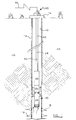
- Figure 1 is a partial cross-sectional view of a subterranean wellbore with an ESP suspended on a conduit therein, in accordance with one preferred method of the present invention.
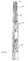
- Figure 2 is a partial cross-sectional view of a conduit connected to an ESP, and with an electric cable floating there within, in accordance with one preferred method of the present invention.
- ESP electric submergible pumping system
- Figure 1 shows a wellbore 10, used for recovering fluids such as water and/or hydrocarbons, that penetrates one or more subterranean earthen formations 12.
- the wellbore 10 includes a wellhead 14 removably connected to an upper portion of a production tubing and/or casing string 16, as is well known to those skilled in the art. If the casing string 16 extends across a fluid producing subterranean formation 12, then the casing string 16 can include at least one opening or perforation 18 for permitting fluids to enter the interior thereof.
- An electric submergible pumping system (“ESP”) 20 is shown suspended within the casing string 16, and generally includes an electric motor 22, an oil-filled motor protector 24, and a pump 26.
- the ESP 20 is shown in Figure 1 in an upside-down arrangement with the motor 22 above the pump 26; however, it should be understood that the present invention can be used when the ESP 20 is deployed in a conventional configuration with the motor 22 below the pump 26.
- ESP electric submergible pumping system
- the terms “upper” and “lower”, “above” and “below”, “uphole” and “downhole”, and “upwardly” and “downwardly” are relative terms to indicate position and direction of movement in easily recognized terms. Usually, these terms are relative to a line drawn from an upmost position at the surface of the earth to a point at the center of the earth, and would be appropriate for use in relatively straight, vertical wellbores. However, when the wellbore is highly deviated, such as from about 60 degrees from vertical, or horizontal, these terms do not make sense and therefore should not be taken as limitations. These terms are only used for ease of understanding as an indication of what the position or movement would be if taken within a vertical wellbore.
- the ESP 20 is operatively connected to a lower end of a conduit 28, such as a plurality of lengths of jointed tubing, or to a length of coiled tubing that has been spooled into the casing 16, as is well known to those skilled in the art.
- the conduit 28 can be of any commercially available size (ie. outside/inside diameter) and formed from any material suitable to the wellbore conditions, as all is well known in the art.
- typical sizes of coiled tubing are from 0.75" OD to 3.5" OD, and are made from aluminum, steel, titanium, and alloys thereof.
- One end of an electrical cable 30 is operatively connected to the ESP 20 to provide electrical power to the motor 22, and is operatively connected at an opposite end at the earth's surface to electrical control equipment and a source of electrical power (both not shown), as are both well known in the art.
- Electrical cable 30 typically used with ESP's 20 does not have sufficient internal strength to support its own freely suspended weight; therefore, in the past a plurality of cable anchor assemblies were inserted within the coiled tubing. The prior cable anchor assemblies were used to transfer the weight of the cable to the coiled tubing.
- the present invention does not use cable anchors, but instead relies on the concept of "floating" the cable 30 within its conduit 28.
- float means the use of a fluid within the conduit 28 that has a density (i.e., weight per unit volume) that is approximately equal to or greater than the density of the cable 30, so that the cable 30 will be self supporting or be buoyant within the fluid.
- density i.e., weight per unit volume
- the cable 30 will not compress and damage the electrical connectors, as when the prior cable anchors slipped. In the event that the cable 30 is to be removed from the coiled tubing, the cable can simply be pulled out, because there are no anchors or other gripping devices to impede the movement of the cable.
- the cable 30 is inserted into the conduit 28, such as coiled tubing, by any of the methods as described in the above referenced prior patents. This can take place during the manufacture of the coiled tubing or in the field.
- One preferred filed method is to unspool the coiled tubing on the ground, run a guide wire therethrough, attach one end of the guide wire to the cable and attach the other end of the guide wire to a vehicle.
- the cable is coated with a friction-reducing agent, such as grease or oil, and the vehicle is then moved to pull the cable into the coiled tubing.
- the cable 30 has been inserted into the coiled tubing 28, one end thereof, which will be the lowermost end adjacent the ESP 20, extends out from one end of the coiled tubing 28 and is sealed, such as by a pressure fitted connector and/or cap 32, as is well known to those skilled in the art.
- the interior of the conduit 28 is filled with a fluid 34, such as drilling mud, of sufficient density to float the electric cable 30 within the conduit 28 when the conduit 28 is disposed within the wellbore 10.
- the fluid- and cable-filled coiled tubing 28 is then respooled, and transported into position adjacent the wellbore 10.
- the ESP 20 is connected to the lower end of the conduit 28, as is well known to those skilled in the art, and the lower end of the electric cable 30 is operatively connected to the motor 22.
- the ESP 20 is lowered into the wellbore 10, such as by the use of an injector head (not shown), as is well known to those skilled in the art.
- the upper end of the coiled tubing 28 is sealed by the wellhead 14, as is well known to those skilled in the art, and the upper end of the cable 30 is operatively connected to a power source.
- An alternate preferred method of installing the cable 30 within the coiled tubing 28 comprises including one or more tubes within the cable 30, as is well known to those skilled in the art, or attached to the outside thereof.
- the cable 28 is pulled through the coiled tubing 28 as before, a bottom end of the coiled tubing 28 is sealed, and then the chosen fluid is injected through the tube into the coiled tubing 28.
- a variation on this method is to pump the chosen fluid into the coiled tubing 28 after the cable 30 is installed therein, and permit air to escape out through a second of the tubes.
- the use of one or more tubes permits relatively easy removal and addition of the fluid and/or additives to the fluid to change its density.
- Another preferred method of installing the cable 30 within the coiled tubing 28 comprises sealing a lower end of the cable 30 within the coiled tubing 28, and then pumping a fluid, such as air or the chosen fluid to float the cable, into the coiled tubing 28 to hydraulically push the cable 30 into and through the coiled tubing 28.
- a fluid such as air or the chosen fluid to float the cable
- fluid 34 is either added to or removed from the conduit, if necessary, to ensure that the cable 30 is approximately neutrally buoyant within the conduit 28.
- the density of the fluid 34 can be changed by the circulating into the conduit 28 additives and/or other fluids of varying densities to create a fluid within the conduit 28 that will "float" the cable 30. If not enough fluid is used or if the density of the fluid is too low, then the cable will sink within the conduit, stretch or damage the conductors, and compress the lower electrical motor connector and/or cap 32. As stated previously, this compression should be avoided to prevent electrical failures of the ESP 20. If too much fluid is used or if the fluid density of the fluid is too high, then the cable 30 will tend to rise within the conduit and stretch the electrical motor connector and compress any surface electrical connectors.
- the fluid 34 needs to have a density that is approximately equal to (e.g., may be slightly less than) or greater than the density of the cable 30. It should be understood that the density of the cable 30 may change over time, so the density of the fluid 34 may need to be selected to be slightly under or over the optimum density to float the cable 30 upon its installation. For example, the EPDM or nitrile rubber in the jacket of the cable 30 will absorb oil and thus will swell. This absorption of oil reduces the density of the cable 30. So, the density of the fluid 34 can be altered to compensate for this absorption of oil at the time of the initial installation of the fluid 34 or during the operation of the ESP 20.
- the tension on the cable 30 can be measured at the earth's surface, as is well known to those skilled in the art, and adjustments can be made in the density of the fluid 34 at that time to ensure that the cable 30 is properly "floating" within the coiled tubing 28.
- the fluid 34 preferably will have a specific gravity greater than 1 and up to about 5.
- This fluid can be a liquid, emulsion, foam or a gel.
- Preferred fluids include any hydrocarbon-based liquid, such as wellbore fluids, oil, diesel fuel, oil-based drilling mud, or water-based liquid, such as water, brine, sea water, water-based drilling mud.
- other materials can be added to the fluid 34 to increase or decrease its density, such as weighting material, barite, bentonite, lost circulation materials, spheres of material, such as float ash, ceramic beads, Styrofoam, and the like.
- the inventors hereof have made calculations illustrating two sample installations of floating cable within coiled tubing.
- a commercially available #2 C/S PPEO 5 kV armoured cable has a calculated density of about 3.638 grams/cubic centimetres.
- the fluid needed to float the cable would have a density of approximately 3.60 grams/cubic centimetres or about 30.3 Ibs/gallon. This density of fluid is commonly achievable in the drilling industry.
- the resulting pressure of the fluid, measured at the downhole cable connector is about 9,500 pounds per square inch, which is well within the pressure rating of commercially available coiled tubing and of commercially available cable connectors.
- a commercially available #2 C/S ETBE 5 kV armoured cable within a 0.25 inch diameter injection tube therein has a calculated density of about 4.317 grams/cubic centimetres.
- the fluid needed to float the cable would have a density of approximately 4.32 grams/cubic centimetres or about 36.0 Ibs/gallon. This density of fluid is commonly achievable in the drilling industry. If the coiled tubing is 6,000 feet in length, then the resulting pressure of the fluid, measured at the downhole cable connector, is about 11,500 pounds per square inch, which is well within the pressure rating of commercially available coiled tubing and of commercially available cable connectors.
- the present invention provides a novel method and related components for suspending an ESP within a wellbore using the concept of"floating" the cable to therefore eliminate the need for and the problems with cable anchors or other devices to transfer the weight of the cable to the conduit.
Abstract
Description
Claims (21)
- A conduit for suspension within a wellbore, comprising: a length of conduit; electric cable disposed within the conduit; and means within the conduit for floating the electric cable within the conduit.
- A conduit of Claim 1, wherein the means for floating comprises a fluid having a density approximately equal to or greater than the density of the electric cable.
- A conduit of Claim 1 or Claim 2, wherein the conduit comprises a plurality of lengths of jointed tubing.
- A conduit of Claim 1 or Claim 2, wherein the conduit comprises a length of coiled tubing.
- A conduit of any of the preceding claims and further comprising an electric submergible pumping system operatively connected to one end of the electric cable.
- A conduit of Claim 5 wherein the electric submergible pumping system is connected to one end of the conduit.
- An electric submergible pumping system comprising: a length of conduit for suspension within a wellbore; a pump operatively connected to an electric motor, with the pump connected to one end of the conduit; an electric cable disposed within the conduit; and fluid within the conduit of sufficient volume and sufficient density to float the electric cable within the conduit.
- An electric submergible pumping system of Claim 7, wherein the density of the fluid is approximately equal to or greater than the density of the electric cable.
- An electric submergible pumping system of Claim 8, wherein the conduit comprises a plurality of lengths of jointed tubing.
- An electric submergible pumping system of Claim 8, wherein the conduit comprises a length of coiled tubing.
- An electric submergible pumping system of any of Claims 7 to 10, wherein the fluid is drilling mud.
- An electric submergible pumping system of any of Claims 7 to 11, wherein the fluid has a specific gravity of between 1 and about 5.
- A method of installing an electric cable within a conduit, comprising:(a) inserting an electric cable within a conduit; and(b) filling the conduit with a fluid of sufficient volume and sufficient density to float the electric cable within the conduit when the conduit is disposed within a wellbore.
- The method of Claim 13 and further comprising connecting an electric submergible pumping system to the one end of the conduit.
- The method of Claim 13 and further comprising operatively connecting the one end of the electric cable to an electric motor of the electric submergible pumping system.
- The method of any of Claims 13 to 15, wherein the density of the fluid is approximately equal to or greater than the density of the electric cable.
- The method of any of Claims 13 to 16, wherein the conduit comprises a plurality of lengths of jointed tubing.
- The method of any of Claims 13 to 16, wherein the conduit comprises a length of coiled tubing.
- The method of any of Claims 13 to 18, wherein the fluid is drilling mud.
- The method of any of Claims 13 to 19, wherein the fluid has a specific gravity of between 1 and about 5.
- A method of suspending an electric submergible pumping system within a wellbore, comprising:(a) inserting an electric cable within a conduit;(b) filling the conduit with a fluid of sufficient volume and sufficient density to float the electric cable within the conduit when the conduit is disposed within a wellbore;(c) connecting an electric submergible pumping system to the one end of the conduit;(d) operatively connecting the one end of the electric cable to an electric motor of the electric submergible pumping system; and(e) inserting the electric submergible pumping system and the conduit into the wellbore.
Applications Claiming Priority (2)
| Application Number | Priority Date | Filing Date | Title |
|---|---|---|---|
| US08/867,018 US5906242A (en) | 1997-06-03 | 1997-06-03 | Method of suspending and ESP within a wellbore |
| US867018 | 1997-06-03 |
Publications (3)
| Publication Number | Publication Date |
|---|---|
| EP0882868A2 true EP0882868A2 (en) | 1998-12-09 |
| EP0882868A3 EP0882868A3 (en) | 1999-07-07 |
| EP0882868B1 EP0882868B1 (en) | 2002-06-05 |
Family
ID=25348911
Family Applications (1)
| Application Number | Title | Priority Date | Filing Date |
|---|---|---|---|
| EP98301357A Expired - Lifetime EP0882868B1 (en) | 1997-06-03 | 1998-02-25 | Method of suspending an ESP within a wellbore |
Country Status (5)
| Country | Link |
|---|---|
| US (1) | US5906242A (en) |
| EP (1) | EP0882868B1 (en) |
| CA (1) | CA2239590C (en) |
| DE (1) | DE69805701D1 (en) |
| NO (1) | NO314854B1 (en) |
Cited By (2)
| Publication number | Priority date | Publication date | Assignee | Title |
|---|---|---|---|---|
| WO2010070305A3 (en) * | 2008-12-19 | 2010-10-07 | Artificial Lift Company Limited | Cables for downhole use |
| CN102287168A (en) * | 2011-07-22 | 2011-12-21 | 宝鸡石油钢管有限责任公司 | Steel oil extraction device with continuous oil pumping pipe |
Families Citing this family (17)
| Publication number | Priority date | Publication date | Assignee | Title |
|---|---|---|---|---|
| US6298917B1 (en) * | 1998-08-03 | 2001-10-09 | Camco International, Inc. | Coiled tubing system for combination with a submergible pump |
| US6179585B1 (en) * | 1998-08-24 | 2001-01-30 | Camco International, Inc. | Modular plug connector for use with a submergible pumping system |
| US6582145B1 (en) | 2000-09-13 | 2003-06-24 | Schlumberger Technology Corporation | Pressurized connector for high pressure applications |
| US6727828B1 (en) | 2000-09-13 | 2004-04-27 | Schlumberger Technology Corporation | Pressurized system for protecting signal transfer capability at a subsurface location |
| US6341652B1 (en) | 2000-09-13 | 2002-01-29 | Schlumberger Technology Corporation | Backflow prevention device |
| US7396216B2 (en) * | 2002-04-23 | 2008-07-08 | Halliburton Energy Services, Inc. | Submersible pump assembly for removing a production inhibiting fluid from a well and method for use of same |
| US20040188096A1 (en) * | 2003-03-28 | 2004-09-30 | Traylor Leland B. | Submersible pump deployment and retrieval system |
| US20050045343A1 (en) * | 2003-08-15 | 2005-03-03 | Schlumberger Technology Corporation | A Conduit Having a Cable Therein |
| EP1852571A1 (en) * | 2006-05-03 | 2007-11-07 | Services Pétroliers Schlumberger | Borehole cleaning using downhole pumps |
| US7905295B2 (en) * | 2008-09-26 | 2011-03-15 | Baker Hughes Incorporated | Electrocoil tubing cable anchor method |
| US20100212914A1 (en) * | 2009-02-20 | 2010-08-26 | Smith International, Inc. | Hydraulic Installation Method and Apparatus for Installing a Submersible Pump |
| US8443900B2 (en) | 2009-05-18 | 2013-05-21 | Zeitecs B.V. | Electric submersible pumping system and method for dewatering gas wells |
| US8408312B2 (en) | 2010-06-07 | 2013-04-02 | Zeitecs B.V. | Compact cable suspended pumping system for dewatering gas wells |
| US9482078B2 (en) | 2012-06-25 | 2016-11-01 | Zeitecs B.V. | Diffuser for cable suspended dewatering pumping system |
| WO2015023282A1 (en) * | 2013-08-15 | 2015-02-19 | Halliburton Energy Services, Inc. | Retrievable electrical submersible pump |
| CA2849132C (en) | 2014-04-17 | 2021-04-27 | Gerald V. Chalifoux | Method and apparatus for supporting cables within coiled tubing |
| US11933123B2 (en) * | 2022-03-15 | 2024-03-19 | Saudi Arabian Oil Company | Anchoring a progressive cavity pump in a wellbore |
Citations (12)
| Publication number | Priority date | Publication date | Assignee | Title |
|---|---|---|---|---|
| US3835929A (en) | 1972-08-17 | 1974-09-17 | Shell Oil Co | Method and apparatus for protecting electrical cable for downhole electrical pump service |
| US4336415A (en) | 1980-05-16 | 1982-06-22 | Walling John B | Flexible production tubing |
| US4346256A (en) | 1980-04-01 | 1982-08-24 | Kobe, Inc. | Conduit in supplying electrical power and pressurized fluid to a point in a subterranean well |
| US4830113A (en) | 1987-11-20 | 1989-05-16 | Skinny Lift, Inc. | Well pumping method and apparatus |
| US4881169A (en) | 1986-11-10 | 1989-11-14 | Nec Corporation | Apparatus for controlling peripheral equipment |
| US5145007A (en) | 1991-03-28 | 1992-09-08 | Camco International Inc. | Well operated electrical pump suspension method and system |
| US5146982A (en) | 1991-03-28 | 1992-09-15 | Camco International Inc. | Coil tubing electrical cable for well pumping system |
| US5180014A (en) | 1991-02-14 | 1993-01-19 | Otis Engineering Corporation | System for deploying submersible pump using reeled tubing |
| US5191173A (en) | 1991-04-22 | 1993-03-02 | Otis Engineering Corporation | Electrical cable in reeled tubing |
| US5193614A (en) | 1991-02-26 | 1993-03-16 | Otis Engineering Corporation | Cable anchor assembly |
| US5269377A (en) | 1992-11-25 | 1993-12-14 | Baker Hughes Incorporated | Coil tubing supported electrical submersible pump |
| US5435351A (en) | 1992-03-31 | 1995-07-25 | Head; Philip F. | Anchored wavey conduit in coiled tubing |
Family Cites Families (12)
| Publication number | Priority date | Publication date | Assignee | Title |
|---|---|---|---|---|
| US1912794A (en) * | 1925-11-10 | 1933-06-06 | Thomas F Peterson | High tension cable |
| NL25755C (en) * | 1928-03-22 | |||
| US3650324A (en) * | 1970-10-12 | 1972-03-21 | Paul R Randles | Well pumping system construction |
| US4009756A (en) * | 1975-09-24 | 1977-03-01 | Trw, Incorporated | Method and apparatus for flooding of oil-bearing formations by downward inter-zone pumping |
| US4262226A (en) * | 1979-08-22 | 1981-04-14 | Kobe, Inc. | Insulating fluid system for protecting submersible electric motors from surrounding fluids |
| US4616955A (en) * | 1984-10-18 | 1986-10-14 | Bechtel International Corporation | Method and apparatus for encasing pipeline or cable |
| GB2178185B (en) * | 1985-07-24 | 1990-01-17 | Stc Plc | Optical fibre cable |
| US4681169A (en) * | 1986-07-02 | 1987-07-21 | Trw, Inc. | Apparatus and method for supplying electric power to cable suspended submergible pumps |
| US4928771A (en) * | 1989-07-25 | 1990-05-29 | Baker Hughes Incorporated | Cable suspended pumping system |
| US5211225A (en) * | 1991-08-23 | 1993-05-18 | Grosch Wayne A | Submersible pump adapter |
| US5293931A (en) * | 1992-10-26 | 1994-03-15 | Nichols Ralph L | Modular, multi-level groundwater sampler |
| GB9621235D0 (en) * | 1996-10-11 | 1996-11-27 | Head Philip | Conduit in coiled tubing system |
-
1997
- 1997-06-03 US US08/867,018 patent/US5906242A/en not_active Expired - Lifetime
-
1998
- 1998-02-25 DE DE69805701T patent/DE69805701D1/en not_active Expired - Lifetime
- 1998-02-25 EP EP98301357A patent/EP0882868B1/en not_active Expired - Lifetime
- 1998-05-29 NO NO19982455A patent/NO314854B1/en not_active IP Right Cessation
- 1998-06-03 CA CA002239590A patent/CA2239590C/en not_active Expired - Fee Related
Patent Citations (12)
| Publication number | Priority date | Publication date | Assignee | Title |
|---|---|---|---|---|
| US3835929A (en) | 1972-08-17 | 1974-09-17 | Shell Oil Co | Method and apparatus for protecting electrical cable for downhole electrical pump service |
| US4346256A (en) | 1980-04-01 | 1982-08-24 | Kobe, Inc. | Conduit in supplying electrical power and pressurized fluid to a point in a subterranean well |
| US4336415A (en) | 1980-05-16 | 1982-06-22 | Walling John B | Flexible production tubing |
| US4881169A (en) | 1986-11-10 | 1989-11-14 | Nec Corporation | Apparatus for controlling peripheral equipment |
| US4830113A (en) | 1987-11-20 | 1989-05-16 | Skinny Lift, Inc. | Well pumping method and apparatus |
| US5180014A (en) | 1991-02-14 | 1993-01-19 | Otis Engineering Corporation | System for deploying submersible pump using reeled tubing |
| US5193614A (en) | 1991-02-26 | 1993-03-16 | Otis Engineering Corporation | Cable anchor assembly |
| US5145007A (en) | 1991-03-28 | 1992-09-08 | Camco International Inc. | Well operated electrical pump suspension method and system |
| US5146982A (en) | 1991-03-28 | 1992-09-15 | Camco International Inc. | Coil tubing electrical cable for well pumping system |
| US5191173A (en) | 1991-04-22 | 1993-03-02 | Otis Engineering Corporation | Electrical cable in reeled tubing |
| US5435351A (en) | 1992-03-31 | 1995-07-25 | Head; Philip F. | Anchored wavey conduit in coiled tubing |
| US5269377A (en) | 1992-11-25 | 1993-12-14 | Baker Hughes Incorporated | Coil tubing supported electrical submersible pump |
Cited By (4)
| Publication number | Priority date | Publication date | Assignee | Title |
|---|---|---|---|---|
| WO2010070305A3 (en) * | 2008-12-19 | 2010-10-07 | Artificial Lift Company Limited | Cables for downhole use |
| GB2478472A (en) * | 2008-12-19 | 2011-09-07 | Artificial Lift Co Ltd | Cables for downhole use |
| GB2478472B (en) * | 2008-12-19 | 2013-04-10 | Artificial Lift Co Ltd | Cables for downhole use |
| CN102287168A (en) * | 2011-07-22 | 2011-12-21 | 宝鸡石油钢管有限责任公司 | Steel oil extraction device with continuous oil pumping pipe |
Also Published As
| Publication number | Publication date |
|---|---|
| EP0882868B1 (en) | 2002-06-05 |
| US5906242A (en) | 1999-05-25 |
| DE69805701D1 (en) | 2002-07-11 |
| EP0882868A3 (en) | 1999-07-07 |
| CA2239590A1 (en) | 1998-12-03 |
| NO982455D0 (en) | 1998-05-29 |
| NO982455L (en) | 1998-12-04 |
| CA2239590C (en) | 2007-08-07 |
| NO314854B1 (en) | 2003-06-02 |
Similar Documents
| Publication | Publication Date | Title |
|---|---|---|
| EP0882868B1 (en) | Method of suspending an ESP within a wellbore | |
| US5180014A (en) | System for deploying submersible pump using reeled tubing | |
| US3835929A (en) | Method and apparatus for protecting electrical cable for downhole electrical pump service | |
| US10533381B2 (en) | Wet connection system for downhole equipment | |
| US6220358B1 (en) | Hollow tubing pumping system | |
| US7640993B2 (en) | Method of deploying and powering an electrically driven in a well | |
| US10428630B2 (en) | Apparatus, system and method for live well artificial lift completion | |
| CA2245502C (en) | Method of suspending an esp within a wellbore | |
| US4051456A (en) | Apparatus for establishing and maintaining electric continuity in drill pipe | |
| CA2242441C (en) | Cable anchors | |
| GB2297105A (en) | Riser assembly | |
| CA2907922C (en) | Methods and systems for deploying cable into a well | |
| CA1209462A (en) | Method and apparatus for conducting wireline operations in a borehole | |
| WO2009065574A2 (en) | Deployment of a wireline tool | |
| US3754607A (en) | Equipment for use in offshore wells | |
| CA2240037C (en) | Cable anchor assembly | |
| US4231436A (en) | Marine riser insert sleeves | |
| US10975630B1 (en) | Expansion tubing joint with extendable cable | |
| US9404347B1 (en) | Apparatus and method for connecting a riser from an offshore rig to a subsea structure | |
| GB2478108A (en) | Method of deploying and powering an electrically driven device in a well | |
| EP0881355A2 (en) | System for deploying an electrical submersible pump within a wellbore | |
| NZ206908A (en) | Connecting wireline to tool at drill string bottom | |
| CA2731039A1 (en) | Method of deploying and powering an electrically driven device in a well |
Legal Events
| Date | Code | Title | Description |
|---|---|---|---|
| PUAI | Public reference made under article 153(3) epc to a published international application that has entered the european phase |
Free format text: ORIGINAL CODE: 0009012 |
|
| AK | Designated contracting states |
Kind code of ref document: A2 Designated state(s): DE FR GB |
|
| AX | Request for extension of the european patent |
Free format text: AL;LT;LV;MK;RO;SI |
|
| PUAL | Search report despatched |
Free format text: ORIGINAL CODE: 0009013 |
|
| AK | Designated contracting states |
Kind code of ref document: A3 Designated state(s): AT BE CH DE DK ES FI FR GB GR IE IT LI LU MC NL PT SE |
|
| AX | Request for extension of the european patent |
Free format text: AL;LT;LV;MK;RO;SI |
|
| RIC1 | Information provided on ipc code assigned before grant |
Free format text: 6E 21B 17/00 A |
|
| 17P | Request for examination filed |
Effective date: 19990812 |
|
| AKX | Designation fees paid |
Free format text: DE FR GB |
|
| 17Q | First examination report despatched |
Effective date: 20001013 |
|
| GRAG | Despatch of communication of intention to grant |
Free format text: ORIGINAL CODE: EPIDOS AGRA |
|
| GRAG | Despatch of communication of intention to grant |
Free format text: ORIGINAL CODE: EPIDOS AGRA |
|
| GRAH | Despatch of communication of intention to grant a patent |
Free format text: ORIGINAL CODE: EPIDOS IGRA |
|
| GRAH | Despatch of communication of intention to grant a patent |
Free format text: ORIGINAL CODE: EPIDOS IGRA |
|
| GRAA | (expected) grant |
Free format text: ORIGINAL CODE: 0009210 |
|
| AK | Designated contracting states |
Kind code of ref document: B1 Designated state(s): DE FR GB |
|
| PG25 | Lapsed in a contracting state [announced via postgrant information from national office to epo] |
Ref country code: FR Free format text: LAPSE BECAUSE OF FAILURE TO SUBMIT A TRANSLATION OF THE DESCRIPTION OR TO PAY THE FEE WITHIN THE PRESCRIBED TIME-LIMIT Effective date: 20020605 |
|
| REG | Reference to a national code |
Ref country code: GB Ref legal event code: FG4D |
|
| REF | Corresponds to: |
Ref document number: 69805701 Country of ref document: DE Date of ref document: 20020711 |
|
| PG25 | Lapsed in a contracting state [announced via postgrant information from national office to epo] |
Ref country code: DE Free format text: LAPSE BECAUSE OF FAILURE TO SUBMIT A TRANSLATION OF THE DESCRIPTION OR TO PAY THE FEE WITHIN THE PRESCRIBED TIME-LIMIT Effective date: 20020906 |
|
| EN | Fr: translation not filed | ||
| PLBE | No opposition filed within time limit |
Free format text: ORIGINAL CODE: 0009261 |
|
| STAA | Information on the status of an ep patent application or granted ep patent |
Free format text: STATUS: NO OPPOSITION FILED WITHIN TIME LIMIT |
|
| 26N | No opposition filed |
Effective date: 20030306 |
|
| PGFP | Annual fee paid to national office [announced via postgrant information from national office to epo] |
Ref country code: GB Payment date: 20150225 Year of fee payment: 18 |
|
| GBPC | Gb: european patent ceased through non-payment of renewal fee |
Effective date: 20160225 |
|
| PG25 | Lapsed in a contracting state [announced via postgrant information from national office to epo] |
Ref country code: GB Free format text: LAPSE BECAUSE OF NON-PAYMENT OF DUE FEES Effective date: 20160225 |