EP0882593A1 - Method for forming a hydrophobic/hydrophilic front face of an ink jet printhead - Google Patents
Method for forming a hydrophobic/hydrophilic front face of an ink jet printhead Download PDFInfo
- Publication number
- EP0882593A1 EP0882593A1 EP98303121A EP98303121A EP0882593A1 EP 0882593 A1 EP0882593 A1 EP 0882593A1 EP 98303121 A EP98303121 A EP 98303121A EP 98303121 A EP98303121 A EP 98303121A EP 0882593 A1 EP0882593 A1 EP 0882593A1
- Authority
- EP
- European Patent Office
- Prior art keywords
- hydrophobic
- hydrophilic
- film
- printhead
- ink
- Prior art date
- Legal status (The legal status is an assumption and is not a legal conclusion. Google has not performed a legal analysis and makes no representation as to the accuracy of the status listed.)
- Withdrawn
Links
Images


Classifications
-
- B—PERFORMING OPERATIONS; TRANSPORTING
- B41—PRINTING; LINING MACHINES; TYPEWRITERS; STAMPS
- B41J—TYPEWRITERS; SELECTIVE PRINTING MECHANISMS, i.e. MECHANISMS PRINTING OTHERWISE THAN FROM A FORME; CORRECTION OF TYPOGRAPHICAL ERRORS
- B41J2/00—Typewriters or selective printing mechanisms characterised by the printing or marking process for which they are designed
- B41J2/005—Typewriters or selective printing mechanisms characterised by the printing or marking process for which they are designed characterised by bringing liquid or particles selectively into contact with a printing material
- B41J2/01—Ink jet
- B41J2/135—Nozzles
- B41J2/16—Production of nozzles
- B41J2/1606—Coating the nozzle area or the ink chamber
Definitions
- This invention relates generally to an ink jet printer and, more particularly, to a method for forming a front ink ejecting face of a thermal ink jet printhead which is hydrophobic around the periphery of the ink ejecting nozzles and hydrophilic in areas peripheral to the nozzle portions.
- thermal drop-on-demand ink jet printheads There are two general configurations for thermal drop-on-demand ink jet printheads.
- droplets are propelled from nozzles formed in the printhead front face in a direction parallel to the flow of ink in ink channels and parallel to the surface of the bubble-generating heating elements of the printhead, such as, for example, the printhead configuration disclosed in U.S. Patent Re. 32,572, the disclosure of which is totally incorporated herein by reference.
- This configuration is sometimes referred to as an edge shooter or a side shooter.
- the other thermal ink jet configuration propels droplets from nozzles in a direction normal to the surface of the bubble-generating heating elements, such as, for example, the printhead disclosed in U.S.
- Patent 4,568,953 the disclosure of which is totally incorporated herein by reference.
- This configuration is sometimes referred to as a roofshooter.
- a fundamental difference between the two configurations lies in the direction of droplet ejection, in that the side shooter configuration ejects droplets in the plane of the substrate having the heating elements, whereas the roofshooter ejects droplets out of the plane of the substrate having the heating elements and in a direction normal thereto.
- the printhead includes one or more ink filled channels, such as disclosed in U.S. Patent No. 4,463,359, to Ayata et al. At one end, these channels communicate with a relatively small ink supply chamber. At the opposite front face end, the channels have an opening referred to as a nozzle.
- a thermal energy generator for example, a resistor, is located in each of the channels a predetermined distance from the nozzles. The resistors are individually addressed with a current pulse to momentarily vaporize ink in the respective channels and thereby form a bubble. As the bubble grows, the ink bulges from the nozzle, but it is contained by the surface tension of the ink as a meniscus.
- the ink still in the channel between the nozzle and bubble starts to move towards the collapsing bubble causing a volumetric contraction of the ink at the nozzle resulting in the separation of the bulging ink as an ink droplet.
- the acceleration of the ink out of the nozzle while the bubble is growing provides momentum and velocity to the droplet in a substantially straight line direction towards a recording medium, such as paper.
- a typical printhead is made from silicon which is a high surface energy material and thus highly hydrophilic. If left completely uncoated, the water and the ink would rapidly spread over the exposed silicon surface.
- the exposed front face of the printhead around the periphery of the nozzles is desirably made as strongly smooth and hydrophobic as possible, and microscopic irregularities are thus avoided, by providing an ink repellent (hydrophobic) coating on the front face, particularly around the nozzles, that repels the ink that is used for the printing process.
- An ink repellent property is a quantifiable physical property that is commonly expressed in terms of the contact angle that a small ink droplet forms with this coating.
- a large contact angle of, for instance, more than 90° indicates a repellent nature of the coating with the ink and smaller contact angles of, for instance, less than 45° indicate that the ink will cover ("wet") the coating.
- Hydrophobic layers coated on the front face of a thermal ink jet printhead are known in the art.
- Methods for coating the front face include spraying or dip coating low energy hydrophobic liquids onto the front face of the printhead or coating a low surface energy material onto an intermediate substrate and then transferring that material onto the front face of the printhead using some combination of pressure and heat.
- U.S. Patents 5,212,496 and 5,218,381 disclose these techniques.
- U.S. Patent No. 5,208,606, to Klein et al. discusses the use of a noble metal as a hydrophobic front face coating.
- the coating may be applied, for example, by electroplating, evaporation, sputtering, ion plating, chemical vapor deposition (CVD) or plasma CVD.
- U.S. Patent No. 5,073,785 to Jansen et al., discloses a process for minimizing or avoiding ink drop deflection in ink jet devices that comprises coating the front face of ink jet head components with amorphous carbon.
- the amorphous or diamond-like carbon layer is subsequently fluorinated with a fluorine-containing gas by plasma enhanced chemical vapor deposition (PECVD) to render its surface stable and hydrophobic.
- PECVD plasma enhanced chemical vapor deposition
- Another technique is to bond a thin low surface energy polymeric film (referred to as a nozzle plate) to the printhead nozzle face and, using a mask, forming holes through the film connecting to the channels of the printhead.
- a nozzle plate a thin low surface energy polymeric film
- This technique is disclosed, for example, in U.S. Patent 5,378,137.
- a remaining problem with prior art printheads is that, despite the hydrophobic treatment of the front face, ink around the nozzles is not dispersed as efficiently as desired; residual ink may still interfere to some extent with drop directionality.
- the Canon BJC 4000 incorporates a printhead which has a unitary nozzle face with a hydrophobic region around the nozzles and a hydrophilic region around the periphery of the front face. It would be desirable to provide this hybrid type of front face wettability with a forming process which is simple and inexpensive and which can be used with various types of printhead front face coatings.
- the invention is directed towards an ink jet printhead having a front face which is hydrophobic at areas around the periphery of the nozzles but which is hydrophilic in areas adjacent to the hydrophobic areas.
- the front face of the printhead is coated with amorphous carbon.
- the carbon is subsequently fluorinated to reduce the surface energy changing the wetting characteristics from hydrophilic to hydrophobic.
- the hydrophobic coating is then patterned by UV laser ablation through a mask removing the coating from selected peripheral areas and exposing the underlying high energy hydrophilic printhead face surface.
- the hydrophilicity of the exposed region can be further increased by ablating in the presence of a polar reactive gas such as ozone or chlorine.
- a high surface energy polymer film is bonded to the printhead front face and the exposed surface fluorinated to reduce the top surface energy making the surface hydrophobic.
- the film is then patterned by laser ablation through a mask removing the fluorinated top film surface from selected peripheral areas to expose remaining portions of the polymer resulting in hydrophobic areas around the nozzles contacting hydrophilic regions at the periphery enabling a wicking action.
- the nozzles can be formed by using a separate masking step.
- the present invention relates to a method for forming the front surface of an ink jet printhead with hydrophobic and hydrophilic regions, the front surface of the printhead having a plurality of ink channels terminating as nozzles at said surface, the method comprising the steps of:
- the invention also relates to a method for forming the front surface of an ink jet printhead with hydrophobic and hydrophilic regions, the front surface of the printhead having a plurality of ink channels terminating in nozzles at said surface, the method comprising the steps of:
- FIG. 1 is a front view of a printhead showing the front ink ejecting face of the printhead having hydrophobic and hydrophilic regions formed by the methods of the present invention.
- FIG. 2 is a cross-sectional side view of the printhead of FIG. 1.
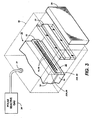
- FIG. 3 is a perspective view of the printhead of FIG. 1 subjected to an ablating laser beam which forms the hydrophilic regions of the front face.
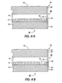
- FIGS. 4A, 4B are cross-sectional side views of the printhead of FIG. 1 showing a second embodiment of hydrophobic/hydrophilic regions formed on the front face.
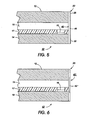
- FIG. 5 is a variation of the FIG. 4 embodiment.
- FIG. 6 is another variation of the FIG. 4 embodiment.
- Printhead 10 includes a first or upper substrate 12 and a second or lower substrate 14.
- the substrates are formed of a hydrophilic semiconductor material, preferably silicon.
- Upper substrate 12 is a channel plate having elongated V-shaped channels 16 formed in the bottom surface thereof by ODE techniques, for example, as disclosed in U.S. Patents Re. 32,572 and 4,947,192, whose contents are hereby incorporated by reference.
- Lower substrate 14 is a heater plate having a plurality of resistive heater elements 15 formed in an upper surface thereof.
- the heater elements 15 of plate 14 correspond in number and position to the channels 16 in channel plate 12.
- the upper surface of the heater plate typically includes a polymeric insulative layer 17 which is patterned to form recesses exposing the individual heating elements.
- This polymeric insulative layer is referred to as a "pit layer" and is sandwiched between the channel plate and heater plate so that the nozzle-containing front face 20 has three layers: the channel plate 12, the pit layer 17 and the heater plate 14.
- the nozzle-containing front face 20 has three layers: the channel plate 12, the pit layer 17 and the heater plate 14.
- the elongated channels 16 may be formed as part of the polymeric insulative layer 17. If this is the case, the channels have substantially rectangular cross sections. In such cases, the nozzle openings 18 may be formed by a subsequent dicing cut. Alternatively, the design may be such that the polymer channels close at the dice cut, and the nozzles 18 may be subsequently opened by laser ablation.
- Channel plate 12 is bonded to layer 17 and heater plate 14 such that the resistive heater elements face the channels 16.
- Channels 16 define ink channels which communicate with an ink manifold (not shown).
- a hydrophobic coating 22 is provided on the printhead front face 20.
- Coating 22 thickness not to scale
- Regions 28, 30 are portions of front face 20 which have been modified to increase the surface hydrophilicity by a process described below.
- hydrophilic regions 28-30 can be modified by extending hydrophilic fingers 32 into hydrophobic regions 26 to enhance "wicking" away from the nozzles. As shown in FIG. 1, the hydrophilic fingers 32 may extend to regions between adjacent nozzles.
- coating 22 is a relatively hydrophilic diamond-like carbon (DLC) film fluorinated to render it hydrophobic using, for example, the process disclosed in U.S. Patent 5,073,785.
- the fluorinated carbon is of the formula CF x , x representing the number of fluorine atoms.
- the coating has a thickness of between 10-100 nm and preferably 50 nm. Coating 22, when first formed, covers the entire front face of the printhead. Portions of coating 22 are selectively removed by laser ablation through a mask as shown in FIG. 3 leaving regions 28, 30.
- an optical system 27 such as an excimer laser with beam shaping optics, directs an intense, UV ablating beam of radiation onto mask 33 which is patterned to allow light to be transmitted through the top and bottom segments aligned with region 28, 30.
- the ablating beam removes regions 22A, 22B of initially formed coating 22 exposing the underlying regions 28, 30; e.g., the exposed hydrophilic silicon surface of printhead face 20.
- the printhead 10 is enclosed within a chamber 50 having an inlet 31 connected to a polar reactive gas source 34 such as ozone or chlorine.
- a polar reactive gas source 34 such as ozone or chlorine.
- ozone is introduced into chamber 50 during the laser ablation of areas 22A, 22B.
- the hydrophilicity of exposed regions 28, 30 is higher than before the ablation, thereby increasing the effectiveness of ink wicked away from hydrophobic areas 26.
- the ink disposal can be further enhanced by modifying the regions 28-30 to form the fingers 32, shown in FIG. 1, using an appropriately tailored mask.
- the nozzles 18 can be formed by a subsequent laser ablation masking step as is known in the art.
- the FIG. 2 embodiment can have a coating applied to the front face, of a low surface energy material which is already strongly hydrophobic.
- Preferred materials are TEFLON-like materials such as polytetrafluoroethylene (PTFE), fluorinated ethylenepropylene copolymer (FEP), perfluorovinylalkylethertetrafluoroethylene copolymer (PFA TEFLON), copolymers thereof, and the like.
- TEFLON-like materials include those fluoropolymers sold under the tradename CYTOPTM and FLUORADTM.
- a film 40 approximately 10-75 ⁇ thick of a high energy material is bonded to the printhead front face.
- Preferred materials for film 40 are polymers including polysulfones, polyethersulfones, polyphenylsulfones, polyimides, polycarbonates, polyesters or mixtures thereof.
- the bottom surface 41 of film 40 is roughened to increase bonding adhesion by a very short exposure etch to a nitrous oxide plasma. The roughening also improves the wetting characteristic of the film and reduces air entrapment at the front face - film 40 interface.
- the exposed surface of film 40 is then fluorinated by the process described above reducing the exposed surface energy.
- Film 40 can then be characterized as having a first surface layer 42 of approximately 50 nm, which is hydrophobic, and an underlying base layer 43.
- FIG. 4B shows film 40 following a patterned laser ablation step which is controlled to remove fluorinated layer 42 from peripheral regions to expose the top surface of base layer 43. It will thus be appreciated that hydrophobic regions (surface of layer 43) are adjacent to hydrophilic regions (surface of layer 42) thus establishing a wicking path for ink to wick away from the areas surrounding the nozzles.
- a variation of this embodiment shown in FIG. 5 is to bond film 40 to the printhead face, as shown in FIG. 4A and coat the top surface of the film with a very thin hydrophobic film 45 using any of the TEFLON-like materials listed for the FIG. 2 embodiment or forming a fluorinated CF x film on the film 40 surface.
- the peripheral areas are again laser ablated to remove a portion of coating 45 (dotted line) to expose the underlying surface of film 40.
- FIG. 6 shows an alternate embodiment where only a portion of the exposed surface of film 40' is fluorinated.
- a hydrophobic layer 42' is formed, as shown, which is adjacent the non-fluorinated surface of the film.
- a hydrophobic region fluorinated surface of layer 42'
- a hydrophilic region unfluorinated surface of film 40'.
- the narrow hydrophilic fingers 32 shown in FIG. 1 can be added to enhance the ink wicking process.
- the laser ablation of the thin film performed with an ozone chamber could be modified to ablate the bare printhead face surface placed in contact with ozone or other polar reactive gas.
Abstract
Methods are provided for forming a printhead nozzle face with regions
adjacent the nozzles being hydrophobic to repel ink from the nozzles while
peripheral regions of the printhead face are hydrophilic to enhance ink wicking
away from the hydrophobic regions. The methods include patterning a
hydrophobic coating using laser ablation to expose adjacent hydrophilic regions.
Various printhead embodiments are described which provide for enhanced
bonding of a high energy film to a printhead front face, the surface of the film
being selectively fluorinated to reduce the surface energy in selected areas
adjacent the nozzles.
Description
This invention relates generally to an ink jet printer and, more
particularly, to a method for forming a front ink ejecting face of a thermal ink jet
printhead which is hydrophobic around the periphery of the ink ejecting nozzles
and hydrophilic in areas peripheral to the nozzle portions.
There are two general configurations for thermal drop-on-demand ink jet
printheads. In one configuration, droplets are propelled from nozzles formed in
the printhead front face in a direction parallel to the flow of ink in ink channels
and parallel to the surface of the bubble-generating heating elements of the
printhead, such as, for example, the printhead configuration disclosed in U.S.
Patent Re. 32,572, the disclosure of which is totally incorporated herein by
reference. This configuration is sometimes referred to as an edge shooter or a
side shooter. The other thermal ink jet configuration propels droplets from
nozzles in a direction normal to the surface of the bubble-generating heating
elements, such as, for example, the printhead disclosed in U.S. Patent 4,568,953,
the disclosure of which is totally incorporated herein by reference. This
configuration is sometimes referred to as a roofshooter. A fundamental
difference between the two configurations lies in the direction of droplet ejection,
in that the side shooter configuration ejects droplets in the plane of the substrate
having the heating elements, whereas the roofshooter ejects droplets out of the
plane of the substrate having the heating elements and in a direction normal
thereto.
In existing thermal ink jet printing, the printhead includes one or more ink
filled channels, such as disclosed in U.S. Patent No. 4,463,359, to Ayata et al.
At one end, these channels communicate with a relatively small ink supply
chamber. At the opposite front face end, the channels have an opening referred
to as a nozzle. A thermal energy generator, for example, a resistor, is located in
each of the channels a predetermined distance from the nozzles. The resistors are
individually addressed with a current pulse to momentarily vaporize ink in the
respective channels and thereby form a bubble. As the bubble grows, the ink
bulges from the nozzle, but it is contained by the surface tension of the ink as a
meniscus. As the bubble begins to collapse, the ink still in the channel between
the nozzle and bubble starts to move towards the collapsing bubble causing a
volumetric contraction of the ink at the nozzle resulting in the separation of the
bulging ink as an ink droplet. The acceleration of the ink out of the nozzle while
the bubble is growing provides momentum and velocity to the droplet in a
substantially straight line direction towards a recording medium, such as paper.
The specific details of the separation of the ink from its physical
surroundings, the ink channel, and the nozzle orifice determine to a large extent
the direction in which the ink will travel to the paper and thus determine where
the mark on the paper will be made. Any microscopic irregularity that would
affect the isotropy of this ink/orifice separation process can cause the ink to travel
in an uncontrolled and unintended direction; not orthogonal to the plane defined
by the front face. This results in poor quality of the images and text that are
printed on the paper. Such irregularities include pools of ink that collect around
the orifice from previous jet firing.
These pools of ink form because of hydrophilic characteristics of the front
face of the printheads surrounding the printhead orifices. A typical printhead is
made from silicon which is a high surface energy material and thus highly
hydrophilic. If left completely uncoated, the water and the ink would rapidly
spread over the exposed silicon surface. The exposed front face of the printhead
around the periphery of the nozzles is desirably made as strongly smooth and
hydrophobic as possible, and microscopic irregularities are thus avoided, by
providing an ink repellent (hydrophobic) coating on the front face, particularly
around the nozzles, that repels the ink that is used for the printing process.
An ink repellent property is a quantifiable physical property that is
commonly expressed in terms of the contact angle that a small ink droplet forms
with this coating. A large contact angle of, for instance, more than 90° indicates
a repellent nature of the coating with the ink and smaller contact angles of, for
instance, less than 45° indicate that the ink will cover ("wet") the coating.
Hydrophobic layers coated on the front face of a thermal ink jet printhead
are known in the art. Methods for coating the front face include spraying or dip
coating low energy hydrophobic liquids onto the front face of the printhead or
coating a low surface energy material onto an intermediate substrate and then
transferring that material onto the front face of the printhead using some
combination of pressure and heat. U.S. Patents 5,212,496 and 5,218,381 disclose
these techniques.
U.S. Patent No. 5,208,606, to Klein et al., discusses the use of a noble
metal as a hydrophobic front face coating. The coating may be applied, for
example, by electroplating, evaporation, sputtering, ion plating, chemical vapor
deposition (CVD) or plasma CVD.
U.S. Patent No. 5,073,785, to Jansen et al., discloses a process for
minimizing or avoiding ink drop deflection in ink jet devices that comprises
coating the front face of ink jet head components with amorphous carbon. The
amorphous or diamond-like carbon layer is subsequently fluorinated with a
fluorine-containing gas by plasma enhanced chemical vapor deposition (PECVD)
to render its surface stable and hydrophobic.
Another technique is to bond a thin low surface energy polymeric film
(referred to as a nozzle plate) to the printhead nozzle face and, using a mask,
forming holes through the film connecting to the channels of the printhead. This
technique is disclosed, for example, in U.S. Patent 5,378,137.
All of the above references are hereby incorporated by reference.
A remaining problem with prior art printheads is that, despite the
hydrophobic treatment of the front face, ink around the nozzles is not dispersed
as efficiently as desired; residual ink may still interfere to some extent with drop
directionality.
A commercial ink jet printer, the Canon BJC 4000 incorporates a
printhead which has a unitary nozzle face with a hydrophobic region around the
nozzles and a hydrophilic region around the periphery of the front face. It would
be desirable to provide this hybrid type of front face wettability with a forming
process which is simple and inexpensive and which can be used with various
types of printhead front face coatings.
The invention is directed towards an ink jet printhead having a front face
which is hydrophobic at areas around the periphery of the nozzles but which is
hydrophilic in areas adjacent to the hydrophobic areas.
In one embodiment, the front face of the printhead is coated with
amorphous carbon. The carbon is subsequently fluorinated to reduce the surface
energy changing the wetting characteristics from hydrophilic to hydrophobic.
The hydrophobic coating is then patterned by UV laser ablation through a mask
removing the coating from selected peripheral areas and exposing the underlying
high energy hydrophilic printhead face surface. The hydrophilicity of the
exposed region can be further increased by ablating in the presence of a polar
reactive gas such as ozone or chlorine.
In another embodiment, a high surface energy polymer film is bonded to
the printhead front face and the exposed surface fluorinated to reduce the top
surface energy making the surface hydrophobic. The film is then patterned by
laser ablation through a mask removing the fluorinated top film surface from
selected peripheral areas to expose remaining portions of the polymer resulting
in hydrophobic areas around the nozzles contacting hydrophilic regions at the
periphery enabling a wicking action.
With either of the two embodiments, the nozzles can be formed by using
a separate masking step.
More particularly, the present invention relates to a method for forming
the front surface of an ink jet printhead with hydrophobic and hydrophilic
regions, the front surface of the printhead having a plurality of ink channels
terminating as nozzles at said surface, the method comprising the steps of:
The invention also relates to a method for forming the front surface of an
ink jet printhead with hydrophobic and hydrophilic regions, the front surface of
the printhead having a plurality of ink channels terminating in nozzles at said
surface, the method comprising the steps of:
FIG. 1 is a front view of a printhead showing the front ink ejecting face
of the printhead having hydrophobic and hydrophilic regions formed by the
methods of the present invention.
FIG. 2 is a cross-sectional side view of the printhead of FIG. 1.
FIG. 3 is a perspective view of the printhead of FIG. 1 subjected to an
ablating laser beam which forms the hydrophilic regions of the front face.
FIGS. 4A, 4B are cross-sectional side views of the printhead of FIG. 1
showing a second embodiment of hydrophobic/hydrophilic regions formed on the
front face.
FIG. 5 is a variation of the FIG. 4 embodiment.
FIG. 6 is another variation of the FIG. 4 embodiment.
Referring now to the drawings and particularly to FIGS. 1 and 2 thereof,
a printhead 10 is illustrated in accordance with the present invention. Printhead
10 includes a first or upper substrate 12 and a second or lower substrate 14. The
substrates are formed of a hydrophilic semiconductor material, preferably silicon.
To avoid ink accumulation on the front face of the printhead adjacent the
nozzles 18, a hydrophobic coating 22, is provided on the printhead front face 20.
Coating 22 (thickness not to scale) extends across the front face and forms a
hydrophobic region 26 around the nozzles. Regions 28, 30 are portions of front
face 20 which have been modified to increase the surface hydrophilicity by a
process described below. Optionally, hydrophilic regions 28-30 can be modified
by extending hydrophilic fingers 32 into hydrophobic regions 26 to enhance
"wicking" away from the nozzles. As shown in FIG. 1, the hydrophilic fingers
32 may extend to regions between adjacent nozzles.
In a first embodiment, coating 22 is a relatively hydrophilic diamond-like
carbon (DLC) film fluorinated to render it hydrophobic using, for example, the
process disclosed in U.S. Patent 5,073,785. The fluorinated carbon is of the
formula CFx, x representing the number of fluorine atoms. The coating has a
thickness of between 10-100 nm and preferably 50 nm. Coating 22, when first
formed, covers the entire front face of the printhead. Portions of coating 22 are
selectively removed by laser ablation through a mask as shown in FIG. 3 leaving
regions 28, 30.
Referring to FIG. 3, an optical system 27, such as an excimer laser with
beam shaping optics, directs an intense, UV ablating beam of radiation onto mask
33 which is patterned to allow light to be transmitted through the top and bottom
segments aligned with region 28, 30. The ablating beam removes regions 22A,
22B of initially formed coating 22 exposing the underlying regions 28, 30; e.g.,
the exposed hydrophilic silicon surface of printhead face 20. According to one
aspect of the invention, the printhead 10 is enclosed within a chamber 50 having
an inlet 31 connected to a polar reactive gas source 34 such as ozone or chlorine.
As a specific example, ozone is introduced into chamber 50 during the laser
ablation of areas 22A, 22B. It has been found that, following this step, the
hydrophilicity of exposed regions 28, 30 is higher than before the ablation,
thereby increasing the effectiveness of ink wicked away from hydrophobic areas
26. The ink disposal can be further enhanced by modifying the regions 28-30 to
form the fingers 32, shown in FIG. 1, using an appropriately tailored mask.
In printhead designs where the nozzles 18 are not opened by methods such
as dicing the front face, the nozzles can be formed by a subsequent laser ablation
masking step as is known in the art.
Alternatively, the FIG. 2 embodiment can have a coating applied to the
front face, of a low surface energy material which is already strongly
hydrophobic. Preferred materials are TEFLON-like materials such as
polytetrafluoroethylene (PTFE), fluorinated ethylenepropylene copolymer (FEP),
perfluorovinylalkylethertetrafluoroethylene copolymer (PFA TEFLON),
copolymers thereof, and the like. Commercially available TEFLON-like
materials include those fluoropolymers sold under the tradename CYTOP™ and
FLUORAD™.
Once the coating is applied, laser ablation is accomplished as described
for the fluorinated DLC film.
In another embodiment shown in FIG. 4A, a film 40 approximately 10-75
µ thick of a high energy material is bonded to the printhead front face. Preferred
materials for film 40 are polymers including polysulfones, polyethersulfones,
polyphenylsulfones, polyimides, polycarbonates, polyesters or mixtures thereof.
The bottom surface 41 of film 40 is roughened to increase bonding adhesion by
a very short exposure etch to a nitrous oxide plasma. The roughening also
improves the wetting characteristic of the film and reduces air entrapment at the
front face - film 40 interface. The exposed surface of film 40 is then fluorinated
by the process described above reducing the exposed surface energy. Film 40 can
then be characterized as having a first surface layer 42 of approximately 50 nm,
which is hydrophobic, and an underlying base layer 43.
FIG. 4B shows film 40 following a patterned laser ablation step which is
controlled to remove fluorinated layer 42 from peripheral regions to expose the
top surface of base layer 43. It will thus be appreciated that hydrophobic regions
(surface of layer 43) are adjacent to hydrophilic regions (surface of layer 42) thus
establishing a wicking path for ink to wick away from the areas surrounding the
nozzles.
A variation of this embodiment shown in FIG. 5 is to bond film 40 to the
printhead face, as shown in FIG. 4A and coat the top surface of the film with a
very thin hydrophobic film 45 using any of the TEFLON-like materials listed for
the FIG. 2 embodiment or forming a fluorinated CFx film on the film 40 surface.
The peripheral areas are again laser ablated to remove a portion of coating 45
(dotted line) to expose the underlying surface of film 40.
FIG. 6 shows an alternate embodiment where only a portion of the
exposed surface of film 40' is fluorinated. A hydrophobic layer 42' is formed, as
shown, which is adjacent the non-fluorinated surface of the film. Thus, again, a
hydrophobic region (fluorinated surface of layer 42') is adjacent a hydrophilic
region (unfluorinated surface of film 40').
It is understood that with any of the above embodiments, the narrow
hydrophilic fingers 32 shown in FIG. 1 can be added to enhance the ink wicking
process.
While the embodiments disclosed herein are preferred, it will be
appreciated from this teaching that various alternative, modifications, variations
or improvements therein may be made by those skilled in the art. For example,
though the above description has focused on individual printhead die scale
applications, the concept can be readily extended to assembled partial width and
full width arrays. The laser ablation patterning could also be used to create other
patterns, the narrow hydrophilic fingers 32 being but one example. Further, while
the hydrophobic coating is shown as covering the silicon nozzle face portions, it
is understood that the coating could be extended to cover adjacent areas of the
cartridge front face.
As another example of possible modifications, the laser ablation of the
thin film performed with an ozone chamber could be modified to ablate the bare
printhead face surface placed in contact with ozone or other polar reactive gas.
Claims (11)
- A method for forming the front surface (20) of an ink jet printhead (10) with hydrophobic and hydrophilic regions (26, 28, 30), the front surface (20) of the printhead (10) having a plurality of ink channels (16) terminating as nozzles (18) at said surface (20), the method comprising the steps of:forming a thin hydrophobic film (22) over the front surface of the printhead andlaser ablating portions of the hydrophobic film (22) to expose an underlying hydrophilic surface (28, 30) whereby the exposed surfaces form hydrophilic regions (28, 30) adjacent to the hydrophobic region (26) of the non-ablated film adjacent the nozzles(18).
- The method of claim 1 wherein the hydrophobic film is a polymer selected from the group comprising polytetrafluoroethylene (PTFE), fluorinated ethylenepropylene copolymer (FEP), perfluorovinylalkylethertetrafluoroethylene copolymer (PFA TEFLON), copolymers thereof, and the like.
- The method of claim 1, wherein a hydrophilic film is bonded to the front surface of the printhead,the exposed surface of the film is fluorinated to decrease the surface energy and render it hydrophobic andperipheral areas of the hydrophobic film are laser ablated to expose the underlying remaining portions of the hydrophilic film whereby the exposed hydrophilic surface acts as a wick to ink collected on the hydrophobic surface.
- The method of claim 3, wherein the hydrophilic film is a polymer selected from the group comprising polysulfones, polyethersulfones, polyphenylsulfones, polyimides, polycarbonates, polyesters or mixtures thereof.
- The method of claim 1, wherein a hydrophilic film is bonded to the front surface of the printhead,the hydrophilic film is coated with a thin film of a low energy hydrophobic material andperipheral areas of the hydrophobic film are laser ablated to expose the surface of the hydrophilic film whereby the exposed hydrophilic surface acts as a wick to ink collected on the adjacent hydrophobic surface.
- The method of claim 5, wherein the hydrophilic film is a polymer selected from the group comprising polysulfones, polyethersulfones, polyphenylsulfones, polyimides, polycarbonates, polyesters or mixtures thereof and the low energy hydrophobic material is selected from the group comprising polytetrafluoroethylene (PTFE), fluoropolymer, ethylenepropylene copolymer (FEP), perfluorovinylalkylethertetrafluoroethylene copolymer (PFA TEFLON), copolymers thereof, and the like.
- A method for forming the front surface of an inkjet printhead with hydrophobic and hydrophilic regions, the front surface of the printhead having a plurality of ink channels terminating in nozzles at said surface, the method comprising the steps of:roughening a surface of a hydrophilic film,bonding the roughened surface to the front surface of the printhead,fluorinating a portion of the film adjacent the nozzles to decrease the surface energy of said portion rendering the fluorinated portion hydrophobic, whereby the non-fluorinated hydrophilic portion of the film acts as a wick to ink collected on the fluorinated hydrophobic portion.
- The method of claim 7 wherein the hydrophilic film is a polymer selected from the group comprising polysulfones, polyethersulfones, polyphenylsulfones, polyimides, polycarbonates, polyesters or mixtures thereof.
- An ink jet printhead having a front face with a plurality of ink channels terminating in nozzles at said front face, the said front face having a hydrophobic region adjacent said nozzles, and a hydrophilic region adjacent said hydrophobic region, the hydrophilic region comprising a film of a hydrophilic material which has been fluorinated to reduce the surface energy whereby the hydrophilic region acts to wick ink away from the hydrophobic region.
- The printhead of claim 9, wherein the hydrophobic region is a high energy material which is fluorinated to decrease the surface energy and the hydrophilic regions comprise the same, unfluorinated material.
- An ink jet printhead according to claims 9 or 10, wherein the said hydrophilic regions including hydrophilic finger paths which extend into the hydrophobic regions to assist wicking of the ink away from the nozzles.
Applications Claiming Priority (2)
| Application Number | Priority Date | Filing Date | Title |
|---|---|---|---|
| US86994597A | 1997-06-05 | 1997-06-05 | |
| US869945 | 1997-06-05 |
Publications (1)
| Publication Number | Publication Date |
|---|---|
| EP0882593A1 true EP0882593A1 (en) | 1998-12-09 |
Family
ID=25354491
Family Applications (1)
| Application Number | Title | Priority Date | Filing Date |
|---|---|---|---|
| EP98303121A Withdrawn EP0882593A1 (en) | 1997-06-05 | 1998-04-23 | Method for forming a hydrophobic/hydrophilic front face of an ink jet printhead |
Country Status (2)
| Country | Link |
|---|---|
| EP (1) | EP0882593A1 (en) |
| JP (1) | JPH10337874A (en) |
Cited By (29)
| Publication number | Priority date | Publication date | Assignee | Title |
|---|---|---|---|---|
| WO2001072423A1 (en) * | 2000-03-28 | 2001-10-04 | NMI Naturwissenschaftliches und Medizinisches Institut an der Universität Tübingen | Microfluid components and method for the surface treatment thereof |
| EP1366905A1 (en) * | 2002-04-11 | 2003-12-03 | Canon Kabushiki Kaisha | Method for manufacturing an ink jet head |
| EP1426186A1 (en) * | 2002-12-02 | 2004-06-09 | Xerox Corporation | Ink jet apparatus |
| WO2006036307A2 (en) * | 2004-08-04 | 2006-04-06 | Biotrove, Inc. | Method and system for registering dispenser array location |
| WO2006105571A1 (en) * | 2005-04-04 | 2006-10-12 | Silverbrook Research Pty Ltd | Method of hydrophobically coating a printhead |
| US7328976B2 (en) | 2005-04-04 | 2008-02-12 | Silverbrook Research Pty Ltd. | Hydrophobically coated printhead |
| US7344226B2 (en) | 2005-04-04 | 2008-03-18 | Silverbrook Research Pty Ltd | Method of hydrophobically coating a printhead |
| WO2008109910A1 (en) * | 2007-03-12 | 2008-09-18 | Silverbrook Research Pty Ltd | Method of fabricating printhead having hydrophobic ink ejection face |
| US7568787B2 (en) | 2007-03-12 | 2009-08-04 | Silverbrook Research Pty Ltd | Printhead including seal membrane |
| US7605009B2 (en) | 2007-03-12 | 2009-10-20 | Silverbrook Research Pty Ltd | Method of fabrication MEMS integrated circuits |
| US7666360B2 (en) | 1999-03-19 | 2010-02-23 | Biotrove, Inc. | Multi-through hole testing plate for high throughput screening |
| US7669967B2 (en) | 2007-03-12 | 2010-03-02 | Silverbrook Research Pty Ltd | Printhead having hydrophobic polymer coated on ink ejection face |
| US7682565B2 (en) | 2002-12-20 | 2010-03-23 | Biotrove, Inc. | Assay apparatus and method using microfluidic arrays |
| WO2010060129A1 (en) * | 2008-11-26 | 2010-06-03 | Silverbrook Research Pty Ltd | Inkjet nozzle assembly having moving roof structure and sealing bridge |
| US7833719B2 (en) | 2000-02-18 | 2010-11-16 | The Board Of Trustees Of The Leland Stanford Junior University | Apparatus and methods for parallel processing of micro-volume liquid reactions |
| US7862734B2 (en) | 2008-11-26 | 2011-01-04 | Silverbrook Research Pty Ltd | Method of fabricating nozzle assembly having moving roof structure and sealing bridge |
| US7901054B2 (en) | 2008-11-26 | 2011-03-08 | Silverbrook Research Pty Ltd | Printhead including moving portions and sealing bridges |
| US7938974B2 (en) | 2007-03-12 | 2011-05-10 | Silverbrook Research Pty Ltd | Method of fabricating printhead using metal film for protecting hydrophobic ink ejection face |
| US7976132B2 (en) | 2007-03-12 | 2011-07-12 | Silverbrook Research Pty Ltd | Printhead having moving roof structure and mechanical seal |
| US8029097B2 (en) | 2008-11-26 | 2011-10-04 | Silverbrook Research Pty Ltd | Inkjet nozzle assembly having moving roof structure and sealing bridge |
| US8029745B2 (en) | 1998-01-12 | 2011-10-04 | Massachusetts Institute Of Technology | Systems for filling a sample array by droplet dragging |
| US8105554B2 (en) | 2004-03-12 | 2012-01-31 | Life Technologies Corporation | Nanoliter array loading |
| US8448904B2 (en) | 2007-03-09 | 2013-05-28 | Macdonald Dettwiler & Associates Inc. | Robotic satellite refuelling tool |
| US8685340B2 (en) | 2002-08-23 | 2014-04-01 | Life Technologies Corporation | Microfluidic transfer pin |
| US20140292932A1 (en) * | 2013-03-28 | 2014-10-02 | Seiko Epson Corporation | Liquid ejecting head and liquid ejecting apparatus |
| US8876255B2 (en) | 2012-07-31 | 2014-11-04 | Hewlett-Packard Development Company, L.P. | Orifice structure for fluid ejection device and method of forming same |
| WO2017065774A1 (en) * | 2015-10-15 | 2017-04-20 | Hewlett-Packard Development Company, L.P. | Service structures in print heads |
| US10213761B2 (en) | 2004-08-04 | 2019-02-26 | Life Technologies Corporation | Coating process for microfluidic sample arrays |
| US11203202B1 (en) | 2020-08-31 | 2021-12-21 | Xerox Corporation | System and method for attenuating ink smears on printhead faceplates during inkjet printhead maintenance |
Families Citing this family (4)
| Publication number | Priority date | Publication date | Assignee | Title |
|---|---|---|---|---|
| JP4087085B2 (en) | 2001-07-06 | 2008-05-14 | 株式会社日立製作所 | Inkjet head |
| KR100468859B1 (en) * | 2002-12-05 | 2005-01-29 | 삼성전자주식회사 | Monolithic inkjet printhead and method of manufacturing thereof |
| WO2006105581A1 (en) | 2005-04-04 | 2006-10-12 | Silverbrook Research Pty Ltd | Printhead assembly suitable for redirecting ejected ink droplets |
| US7377620B2 (en) | 2005-05-26 | 2008-05-27 | Hewlett-Packard Development Company, L.P. | Hydrophobic nozzle exit with improved micro fluid ejection dynamics |
Citations (11)
| Publication number | Priority date | Publication date | Assignee | Title |
|---|---|---|---|---|
| US4463359A (en) | 1979-04-02 | 1984-07-31 | Canon Kabushiki Kaisha | Droplet generating method and apparatus thereof |
| US4568953A (en) | 1982-12-28 | 1986-02-04 | Canon Kabushiki Kaisha | Liquid injection recording apparatus |
| US4947192A (en) | 1988-03-07 | 1990-08-07 | Xerox Corporation | Monolithic silicon integrated circuit chip for a thermal ink jet printer |
| EP0389217A2 (en) * | 1989-03-20 | 1990-09-26 | Xaar Limited | Providing a surface with solvent-wettable and solvent-non-wettable zones |
| US5073785A (en) | 1990-04-30 | 1991-12-17 | Xerox Corporation | Coating processes for an ink jet printhead |
| US5208606A (en) | 1991-11-21 | 1993-05-04 | Xerox Corporation | Directionality of thermal ink jet transducers by front face metalization |
| US5212496A (en) | 1990-09-28 | 1993-05-18 | Xerox Corporation | Coated ink jet printhead |
| US5218381A (en) | 1992-04-28 | 1993-06-08 | Xerox Corporation | Hydrophobic coating for a front face of a printhead in an ink jet printer |
| JPH06344560A (en) * | 1993-06-07 | 1994-12-20 | Canon Inc | Surface treatment of ink jet recording head |
| US5378137A (en) | 1993-05-10 | 1995-01-03 | Hewlett-Packard Company | Mask design for forming tapered inkjet nozzles |
| EP0694400A2 (en) * | 1994-07-29 | 1996-01-31 | Canon Kabushiki Kaisha | Ink jet head, ink jet head cartridge, ink jet recording apparatus and method for making ink jet head |
-
1998
- 1998-04-23 EP EP98303121A patent/EP0882593A1/en not_active Withdrawn
- 1998-05-26 JP JP14445598A patent/JPH10337874A/en active Pending
Patent Citations (11)
| Publication number | Priority date | Publication date | Assignee | Title |
|---|---|---|---|---|
| US4463359A (en) | 1979-04-02 | 1984-07-31 | Canon Kabushiki Kaisha | Droplet generating method and apparatus thereof |
| US4568953A (en) | 1982-12-28 | 1986-02-04 | Canon Kabushiki Kaisha | Liquid injection recording apparatus |
| US4947192A (en) | 1988-03-07 | 1990-08-07 | Xerox Corporation | Monolithic silicon integrated circuit chip for a thermal ink jet printer |
| EP0389217A2 (en) * | 1989-03-20 | 1990-09-26 | Xaar Limited | Providing a surface with solvent-wettable and solvent-non-wettable zones |
| US5073785A (en) | 1990-04-30 | 1991-12-17 | Xerox Corporation | Coating processes for an ink jet printhead |
| US5212496A (en) | 1990-09-28 | 1993-05-18 | Xerox Corporation | Coated ink jet printhead |
| US5208606A (en) | 1991-11-21 | 1993-05-04 | Xerox Corporation | Directionality of thermal ink jet transducers by front face metalization |
| US5218381A (en) | 1992-04-28 | 1993-06-08 | Xerox Corporation | Hydrophobic coating for a front face of a printhead in an ink jet printer |
| US5378137A (en) | 1993-05-10 | 1995-01-03 | Hewlett-Packard Company | Mask design for forming tapered inkjet nozzles |
| JPH06344560A (en) * | 1993-06-07 | 1994-12-20 | Canon Inc | Surface treatment of ink jet recording head |
| EP0694400A2 (en) * | 1994-07-29 | 1996-01-31 | Canon Kabushiki Kaisha | Ink jet head, ink jet head cartridge, ink jet recording apparatus and method for making ink jet head |
Non-Patent Citations (1)
| Title |
|---|
| PATENT ABSTRACTS OF JAPAN vol. 095, no. 003 28 April 1995 (1995-04-28) * |
Cited By (60)
| Publication number | Priority date | Publication date | Assignee | Title |
|---|---|---|---|---|
| US8029745B2 (en) | 1998-01-12 | 2011-10-04 | Massachusetts Institute Of Technology | Systems for filling a sample array by droplet dragging |
| US10195579B2 (en) | 1999-03-19 | 2019-02-05 | Life Technologies Corporation | Multi-through hole testing plate for high throughput screening |
| US7666360B2 (en) | 1999-03-19 | 2010-02-23 | Biotrove, Inc. | Multi-through hole testing plate for high throughput screening |
| US7833719B2 (en) | 2000-02-18 | 2010-11-16 | The Board Of Trustees Of The Leland Stanford Junior University | Apparatus and methods for parallel processing of micro-volume liquid reactions |
| WO2001072423A1 (en) * | 2000-03-28 | 2001-10-04 | NMI Naturwissenschaftliches und Medizinisches Institut an der Universität Tübingen | Microfluid components and method for the surface treatment thereof |
| EP1366905A1 (en) * | 2002-04-11 | 2003-12-03 | Canon Kabushiki Kaisha | Method for manufacturing an ink jet head |
| US6766579B2 (en) | 2002-04-11 | 2004-07-27 | Canon Kabushiki Kaisha | Method for manufacturing an ink jet head |
| US8685340B2 (en) | 2002-08-23 | 2014-04-01 | Life Technologies Corporation | Microfluidic transfer pin |
| EP1426186A1 (en) * | 2002-12-02 | 2004-06-09 | Xerox Corporation | Ink jet apparatus |
| US7682565B2 (en) | 2002-12-20 | 2010-03-23 | Biotrove, Inc. | Assay apparatus and method using microfluidic arrays |
| US8697452B2 (en) | 2002-12-20 | 2014-04-15 | Life Technologies Corporation | Thermal cycling assay apparatus and method |
| US9428800B2 (en) | 2002-12-20 | 2016-08-30 | Life Technologies Corporation | Thermal cycling apparatus and method |
| US8105554B2 (en) | 2004-03-12 | 2012-01-31 | Life Technologies Corporation | Nanoliter array loading |
| US10974247B2 (en) | 2004-03-12 | 2021-04-13 | Life Technologies Corporation | Nanoliter array loading |
| US10065189B2 (en) | 2004-03-12 | 2018-09-04 | Life Technologies Corporation | Nanoliter array loading |
| US9266108B2 (en) | 2004-03-12 | 2016-02-23 | Life Technologies Corporation | Nanoliter array loading |
| US8545772B2 (en) | 2004-03-12 | 2013-10-01 | Life Technologies Corporation | Nanoliter array loading |
| US10213761B2 (en) | 2004-08-04 | 2019-02-26 | Life Technologies Corporation | Coating process for microfluidic sample arrays |
| EP1782075B1 (en) * | 2004-08-04 | 2023-10-04 | Life Technologies Corporation | Method for differentially coating a substrate |
| WO2006036307A2 (en) * | 2004-08-04 | 2006-04-06 | Biotrove, Inc. | Method and system for registering dispenser array location |
| US11154834B2 (en) | 2004-08-04 | 2021-10-26 | Life Technologies Corporation | Coating process for microfluidic sample arrays |
| WO2006036307A3 (en) * | 2004-08-04 | 2006-08-17 | Biotrove Inc | Method and system for registering dispenser array location |
| US7469997B2 (en) | 2005-04-04 | 2008-12-30 | Silverbrook Research Pty Ltd | Printhead unit cell incorporating suspended looped heater element |
| US7344226B2 (en) | 2005-04-04 | 2008-03-18 | Silverbrook Research Pty Ltd | Method of hydrophobically coating a printhead |
| US7328976B2 (en) | 2005-04-04 | 2008-02-12 | Silverbrook Research Pty Ltd. | Hydrophobically coated printhead |
| US7901050B2 (en) | 2005-04-04 | 2011-03-08 | Silverbrook Research Pty Ltd | Printhead integrated circuit with suspended heater elements |
| WO2006105571A1 (en) * | 2005-04-04 | 2006-10-12 | Silverbrook Research Pty Ltd | Method of hydrophobically coating a printhead |
| US7677704B2 (en) | 2005-04-04 | 2010-03-16 | Silverbrook Research Pty Ltd | Printhead unit cell having welled heater element |
| US7984975B2 (en) | 2005-04-04 | 2011-07-26 | Silverbrook Research Pty Ltd | Printhead nozzle cell having photoresist chamber |
| US7984972B2 (en) | 2005-04-04 | 2011-07-26 | Silverbrook Research Pty Ltd | Printhead unit cell having rimmed nozzle plate |
| US7594713B2 (en) | 2005-04-04 | 2009-09-29 | Silverbrook Research Pty Ltd | Inkjet printer with unit cells having suspended heater elements |
| US8448904B2 (en) | 2007-03-09 | 2013-05-28 | Macdonald Dettwiler & Associates Inc. | Robotic satellite refuelling tool |
| EP2121330A1 (en) * | 2007-03-12 | 2009-11-25 | Silverbrook Research Pty. Ltd | Method of fabricating printhead having hydrophobic ink ejection face |
| US7934807B2 (en) | 2007-03-12 | 2011-05-03 | Silverbrook Research Pty Ltd | Printhead integrated circuit comprising polymeric cover layer |
| US8025365B2 (en) | 2007-03-12 | 2011-09-27 | Silverbrook Research Pty Ltd | MEMS integrated circuit with polymerized siloxane layer |
| US7986039B2 (en) | 2007-03-12 | 2011-07-26 | Silverbrook Research Pty Ltd | Wafer assembly comprising MEMS wafer with polymerized siloxane attachment surface |
| US8277024B2 (en) | 2007-03-12 | 2012-10-02 | Zamtec Limited | Printhead integrated circuit having exposed active beam coated with polymer layer |
| EP2121330A4 (en) * | 2007-03-12 | 2013-01-23 | Method of fabricating printhead having hydrophobic ink ejection face | |
| US7976132B2 (en) | 2007-03-12 | 2011-07-12 | Silverbrook Research Pty Ltd | Printhead having moving roof structure and mechanical seal |
| US7794613B2 (en) | 2007-03-12 | 2010-09-14 | Silverbrook Research Pty Ltd | Method of fabricating printhead having hydrophobic ink ejection face |
| US7605009B2 (en) | 2007-03-12 | 2009-10-20 | Silverbrook Research Pty Ltd | Method of fabrication MEMS integrated circuits |
| US7938974B2 (en) | 2007-03-12 | 2011-05-10 | Silverbrook Research Pty Ltd | Method of fabricating printhead using metal film for protecting hydrophobic ink ejection face |
| US8672454B2 (en) | 2007-03-12 | 2014-03-18 | Zamtec Ltd | Ink printhead having ceramic nozzle plate defining movable portions |
| US7669967B2 (en) | 2007-03-12 | 2010-03-02 | Silverbrook Research Pty Ltd | Printhead having hydrophobic polymer coated on ink ejection face |
| US7568787B2 (en) | 2007-03-12 | 2009-08-04 | Silverbrook Research Pty Ltd | Printhead including seal membrane |
| CN101610909B (en) * | 2007-03-12 | 2010-12-29 | 西尔弗布鲁克研究股份有限公司 | Method of fabricating printhead having hydrophobic ink ejection face and printhead |
| WO2008109910A1 (en) * | 2007-03-12 | 2008-09-18 | Silverbrook Research Pty Ltd | Method of fabricating printhead having hydrophobic ink ejection face |
| US7862734B2 (en) | 2008-11-26 | 2011-01-04 | Silverbrook Research Pty Ltd | Method of fabricating nozzle assembly having moving roof structure and sealing bridge |
| US8029097B2 (en) | 2008-11-26 | 2011-10-04 | Silverbrook Research Pty Ltd | Inkjet nozzle assembly having moving roof structure and sealing bridge |
| US7901054B2 (en) | 2008-11-26 | 2011-03-08 | Silverbrook Research Pty Ltd | Printhead including moving portions and sealing bridges |
| KR101311281B1 (en) * | 2008-11-26 | 2013-09-25 | 잼텍 리미티드 | Inkjet nozzle assembly having moving roof structure and sealing bridge |
| US8500247B2 (en) | 2008-11-26 | 2013-08-06 | Zamtec Ltd | Nozzle assembly having polymeric coating on moving and stationary portions of roof |
| WO2010060129A1 (en) * | 2008-11-26 | 2010-06-03 | Silverbrook Research Pty Ltd | Inkjet nozzle assembly having moving roof structure and sealing bridge |
| US8876255B2 (en) | 2012-07-31 | 2014-11-04 | Hewlett-Packard Development Company, L.P. | Orifice structure for fluid ejection device and method of forming same |
| US20140292932A1 (en) * | 2013-03-28 | 2014-10-02 | Seiko Epson Corporation | Liquid ejecting head and liquid ejecting apparatus |
| US9272516B2 (en) * | 2013-03-28 | 2016-03-01 | Seiko Epson Corporation | Liquid ejecting head and liquid ejecting apparatus |
| US10369793B2 (en) | 2015-10-15 | 2019-08-06 | Hewlett-Packard Development Company, L.P. | Service structures in print heads |
| CN108136784A (en) * | 2015-10-15 | 2018-06-08 | 惠普发展公司,有限责任合伙企业 | Enclosed structure in print head |
| WO2017065774A1 (en) * | 2015-10-15 | 2017-04-20 | Hewlett-Packard Development Company, L.P. | Service structures in print heads |
| US11203202B1 (en) | 2020-08-31 | 2021-12-21 | Xerox Corporation | System and method for attenuating ink smears on printhead faceplates during inkjet printhead maintenance |
Also Published As
| Publication number | Publication date |
|---|---|
| JPH10337874A (en) | 1998-12-22 |
Similar Documents
| Publication | Publication Date | Title |
|---|---|---|
| EP0882593A1 (en) | Method for forming a hydrophobic/hydrophilic front face of an ink jet printhead | |
| JP3245193B2 (en) | Print head of inkjet printer | |
| US5949454A (en) | Ink jet head, ink jet head cartridge, ink jet recording apparatus and method for making ink jet head | |
| US5119116A (en) | Thermal ink jet channel with non-wetting walls and a step structure | |
| EP0468712B1 (en) | A method of manufacturing an ink jet head and an ink jet head | |
| US5434606A (en) | Orifice plate for an ink-jet pen | |
| JP5317986B2 (en) | Pattern and apparatus for non-wetting coatings on liquid ejectors | |
| KR100508193B1 (en) | Inkject print nozzle plates | |
| JPH04234663A (en) | Processing for thermal ink jetting nozzle | |
| EP0937579A2 (en) | Ink jet head and manufacturing method thereof, discharge opening plate for head and manufacturing method thereof, and ink jet apparatus with ink jet head | |
| JP3348744B2 (en) | Nozzle plate manufacturing method | |
| WO2008029650A1 (en) | Liquid discharge head and method of manufacturing the same | |
| US8708458B2 (en) | Superoleophobic glass devices and their methods | |
| KR20060082412A (en) | Liquid ejection head, liquid ejection apparatus, and method for fabricating liquid ejection head | |
| IL168176A (en) | Ink jet printhead incorporating an array of nozzle assemblies | |
| EP0661158B1 (en) | Ink jet printing | |
| JP7071159B2 (en) | Substrate for liquid discharge head | |
| WO1994008793A1 (en) | Ink jet head having improved jet port surface, and ink jet apparatus equipped with the ink jet head | |
| KR100530252B1 (en) | Printed Media Production | |
| JP2004042399A (en) | Inkjet recording head | |
| JP2791228B2 (en) | Method of manufacturing inkjet head and inkjet head | |
| US10406813B2 (en) | Liquid ejection head | |
| KR100428650B1 (en) | Method for manufacturing head of ink jet printer | |
| JP4354777B2 (en) | Method for coating an orifice plate | |
| KR101257837B1 (en) | Method for forming hydrophobic coating layer on surface of nozzle plate of inkjet printhead |
Legal Events
| Date | Code | Title | Description |
|---|---|---|---|
| PUAI | Public reference made under article 153(3) epc to a published international application that has entered the european phase |
Free format text: ORIGINAL CODE: 0009012 |
|
| AK | Designated contracting states |
Kind code of ref document: A1 Designated state(s): DE FR GB |
|
| AX | Request for extension of the european patent |
Free format text: AL;LT;LV;MK;RO;SI |
|
| 17P | Request for examination filed |
Effective date: 19990609 |
|
| AKX | Designation fees paid |
Free format text: DE FR GB |
|
| STAA | Information on the status of an ep patent application or granted ep patent |
Free format text: STATUS: THE APPLICATION HAS BEEN WITHDRAWN |
|
| 18W | Application withdrawn |
Withdrawal date: 19990329 |