EP0878330A2 - Vehicle tyre - Google Patents
Vehicle tyre Download PDFInfo
- Publication number
- EP0878330A2 EP0878330A2 EP98303614A EP98303614A EP0878330A2 EP 0878330 A2 EP0878330 A2 EP 0878330A2 EP 98303614 A EP98303614 A EP 98303614A EP 98303614 A EP98303614 A EP 98303614A EP 0878330 A2 EP0878330 A2 EP 0878330A2
- Authority
- EP
- European Patent Office
- Prior art keywords
- conductive
- rubber
- tyre
- tread
- less
- Prior art date
- Legal status (The legal status is an assumption and is not a legal conclusion. Google has not performed a legal analysis and makes no representation as to the accuracy of the status listed.)
- Granted
Links
Images


Classifications
-
- B—PERFORMING OPERATIONS; TRANSPORTING
- B60—VEHICLES IN GENERAL
- B60C—VEHICLE TYRES; TYRE INFLATION; TYRE CHANGING; CONNECTING VALVES TO INFLATABLE ELASTIC BODIES IN GENERAL; DEVICES OR ARRANGEMENTS RELATED TO TYRES
- B60C19/00—Tyre parts or constructions not otherwise provided for
- B60C19/08—Electric-charge-dissipating arrangements
-
- B—PERFORMING OPERATIONS; TRANSPORTING
- B60—VEHICLES IN GENERAL
- B60C—VEHICLE TYRES; TYRE INFLATION; TYRE CHANGING; CONNECTING VALVES TO INFLATABLE ELASTIC BODIES IN GENERAL; DEVICES OR ARRANGEMENTS RELATED TO TYRES
- B60C1/00—Tyres characterised by the chemical composition or the physical arrangement or mixture of the composition
- B60C1/0016—Compositions of the tread
-
- B—PERFORMING OPERATIONS; TRANSPORTING
- B60—VEHICLES IN GENERAL
- B60C—VEHICLE TYRES; TYRE INFLATION; TYRE CHANGING; CONNECTING VALVES TO INFLATABLE ELASTIC BODIES IN GENERAL; DEVICES OR ARRANGEMENTS RELATED TO TYRES
- B60C11/00—Tyre tread bands; Tread patterns; Anti-skid inserts
-
- Y—GENERAL TAGGING OF NEW TECHNOLOGICAL DEVELOPMENTS; GENERAL TAGGING OF CROSS-SECTIONAL TECHNOLOGIES SPANNING OVER SEVERAL SECTIONS OF THE IPC; TECHNICAL SUBJECTS COVERED BY FORMER USPC CROSS-REFERENCE ART COLLECTIONS [XRACs] AND DIGESTS
- Y10—TECHNICAL SUBJECTS COVERED BY FORMER USPC
- Y10S—TECHNICAL SUBJECTS COVERED BY FORMER USPC CROSS-REFERENCE ART COLLECTIONS [XRACs] AND DIGESTS
- Y10S152/00—Resilient tires and wheels
- Y10S152/02—Static discharge
-
- Y—GENERAL TAGGING OF NEW TECHNOLOGICAL DEVELOPMENTS; GENERAL TAGGING OF CROSS-SECTIONAL TECHNOLOGIES SPANNING OVER SEVERAL SECTIONS OF THE IPC; TECHNICAL SUBJECTS COVERED BY FORMER USPC CROSS-REFERENCE ART COLLECTIONS [XRACs] AND DIGESTS
- Y10—TECHNICAL SUBJECTS COVERED BY FORMER USPC
- Y10T—TECHNICAL SUBJECTS COVERED BY FORMER US CLASSIFICATION
- Y10T152/00—Resilient tires and wheels
- Y10T152/10—Tires, resilient
- Y10T152/10495—Pneumatic tire or inner tube
- Y10T152/10513—Tire reinforcement material characterized by short length fibers or the like
Definitions
- the present invention relates to a vehicle tyre improved in rolling resistance and electrical conductivity, more particularly to an improved tread rubber decreased in electrical resistance as well as hysteresis loss.
- Such compounds have a very low hysteresis loss but the electrical resistance is very high. Accordingly, when tyres whose tread is made of such insulating rubber are used, the vehicle body is electrostatically charged and problems such as car fire, radio noise, disturbance of light electrical appliances and the like arise.
- a tyre comprises a tread rubber the radially outer surface of which forms the ground contacting surface of the tyre, the tread rubber comprising at least partially a conductive rubber extending from the radially inner surface of the tread rubber to the ground contacting surface, the conductive rubber being compounded from 100 parts by weight of diene rubber and 2 to 30 parts by weight of conductive short fibres, the conductive short fibres being formed by coating reinforcing short fibres with a conductive substance, and the conductive rubber having a volume resistance of less than 1X10 8 ohm cm.
- tyres are a pneumatic tyre comprising a tread portion 2, a pair of axially spaced bead portions 4 each with a bead core 5 therein, a pair of sidewalls 3 extending between the tread edges and the bead portions 4, a toroidal carcass 6 extending between the bead portions 4, and a belt 7 disposed radially outside the carcass 6 and inside a tread rubber 9.
- the carcass 6 comprises at least on ply of cords extending between the bead portions 4 and turned up around the bead cores 5 to form a pair of turnup portions and a main portion therebetween.
- steel cords and organic fibres cords e.g. polyester, nylon, rayon, aromatic polyamide and the like can be used.
- the belt 7 comprises the usual two crossed plies or so-called breaker plies.
- breaker belt cords steel cords are preferably used.
- the belt further has a bandage ply having cords at substantially zero degrees cord angle to the tyre circumferential direction.
- Each of the bead portions 4 is usually provided between the carcass ply turnup portion and main portion with a bead apex made of hard rubber tapering radially outwardly.
- the tread rubber 9 is disposed radially outside the belt 7 to form the tread portion 2, and the tyre tread or ground contacting face 2S is defined by the radially outer surface of the tread rubber.
- the tread rubber 9 comprises a conductive rubber compound 10 at least partially.
- the conductive rubber compound 10 extends from the radially inner surface to the radially outer surface of the tread rubber 9 to form at least part of the ground contacting face 2S of the tyre.
- the conductive rubber compound 10 is made of 100 parts by weight of a base rubber compound and 2 to 30 parts by weight of conductive short fibres mixed therein.
- the conductive short fibres exceed 30 parts by weight, the energy loss between the conductive short fibres and rubber abruptly increases, and the rolling resistance is not decreased. Further, the conductive rubber compound is increased in complex elastic modulus and the wet performance decreases. Accordingly, the conductive short fibre content is not more than 30 parts by weight. If less than 2 parts by weight, it becomes impossible to obtain even a required minimal conductivity.
- the conductive short fibres are formed by coating reinforcing short fibres with a conductive substance.
- synthetic organic fibres e.g. nylon, rayon, vinylon, polyethylene, polystyrene, polyvinyl chloride, polyvinylidene chloride, aromatic polyamide, polyethylene terephthalate, polypropylene, cellulose and the like; plant fibres made of cellulose and the like such as pulp; and inorganic fibres, e.g. glass, alumina and the like can be used.
- organic fibres such as nylon fibres and pulp are preferably used.
- nylon fibres are preferable for their superior extensibility, flexibility and strength.
- the diameter D is preferably in the range of from 1 to 100 micro meters.
- the length L of the reinforcing short fibres is preferable in the range of from 10 to 6000 micro meters in view of the reinforcing effect. If the length is outside this range, the dispersion of the fibres in the compound is liable to be hindered and it becomes difficult to obtain the desired performance.
- the ratio L/D of the fibre length L to the fibre diameter D is preferably 10 to 2000. If L/D is less than 10, the dispersion of the fibres becomes difficult. If more than 2000, in the ground contacting face of the tyre, microscopic rubber breaks are caused by the reinforcing short fibres and the wear resistance is decreased. Further, the mutually contacting conductive short fibres excessively increase, which increases the internal energy loss and the rolling resistance is liable to increase.
- conductive polymers which principal chain has pi-electron conjugation for example, polypyrrole, polyaniline, alkylenoxide and the like and metal salts can be used.
- conductive polymers are preferably used.
- Compounds having a polypyrrole framework structure or a polyaniline framework structure are preferably used for the stable conductivity.
- a compound having a polypyrrole framework structure, as shown in Fig.1(A), is such a compound each polymer of which has a principal chain which is a pyrrole chain 17 made up of pyrrole rings 17A.
- the compound having a polyaniline framework structure is a compound each polymer of which has the principal chain which, as shown in Fig.1(B), has an aniline chain 18 made up of anilino rings 18A.
- an electron-accepting substance such as iodine, arsenic(V)fluoride and the like or an electron-donating substance such as potassium, sodium and the like.
- a conductive polymer in connection with the coating method, can be formed by polymerising monomers in the existence of reinforcing short fibres.
- the conductive polymer is polypyrrole and the reinforcing short fibres are nylon
- it is formed by putting the fibres into an aqueous solution of ferric chloride (6) hydrate (FeCl 3 -6H 2 O), stirring the solution to diffuse the fibres, adding an aqueous solution of pyrrole, stirring the solution for several hours to allow them to conjugate-bond, taking the fibres out through a filter, washing the fibres in the water and methanol, and finally vacuum drying the fibres.
- ferric chloride (6) hydrate FeCl 3 -6H 2 O
- the conductive substance is a metal salt
- various plating methods such as electroplating and vacuum evaporation method may be used.
- the quantity of the conductive substance for the coat is set in the range of not more than 1 parts by weight with respect to 100 parts by weight of the reinforcing short fibres.
- the thickness of the coat is about 0.02 to about 0.1 mm.
- the above-mentioned base rubber compound contains, as rubber, one of or a combination of diene rubbers such as natural rubber (NR), styrene butadiene rubber (SBR), butadiene rubber (BR), isoprene rubber (IR) and the like.
- diene rubbers such as natural rubber (NR), styrene butadiene rubber (SBR), butadiene rubber (BR), isoprene rubber (IR) and the like.
- S-SBR is especially preferable. Further, it is more preferable to use S-SBR whose glassy-transition temperature is not more than -50°C to decrease the rolling resistance.
- additives for example, rubber reinforcements, sulfur, age resistance additives and the like may be added to the base rubber compound.
- silica is preferably used because silica shows a low hysteresis loss which helps to decrease the rolling resistance.
- the silica content may be 0 to 100 parts by weight, preferably 0 to 70 parts by weight.
- colloidal silica the nitrogen adsorption relative surface (BET) of which is in the range of from 150 to 250 m 2 /g and the dibutyl phthalate (DBP) oil absorption is in the range of not less than 180 ml/100g, is preferably used for the rubber reinforcing effect and processing characteristics of the rubber.
- BET nitrogen adsorption relative surface
- DBP dibutyl phthalate
- the conductive rubber compound 10 preferably contains no carbon black.
- carbon black it is possible to use carbon black.
- furnace black (SAF, ISAF and HAF) furnace black (SAF, ISAF and HAF), acetylene black, kettle black can be used.
- the carbon black content is 0 to 45 parts by weight. If the carbon black content is more than 45 parts by weight, the hysteresis loss increases and the rolling resistance increases. Further, the electrical resistance is fully decreased by the carbon which makes it not necessary to add the conductive short fibres.
- the short fibres can be used as a rubber reinforcement.
- the hysteresis loss further decreases and a minimal rolling resistance is obtained.
- it is better to limit the short fibre content to not more than 30 parts by weight as explained above.
- the conductive short fibres contact each other and the rubber compound 10 is provided with the good conductivity required for a tyre. Further, the required conductivity can be obtained using a minimal amount of conductive substance, and the quantity thereof is greatly reduced in comparison with a method in which the conductive substance is directly added to the base rubber.
- the sidewall rubber and bead rubber forming the sidewall portions 3 and bead portions 4 are made of a conductive rubber compound having a volume resistance of less than 1X10 8 ohm cm. This conductivity is however provided by carbon black according to a conventional method.
- the electrical resistance of the tyre between the tread face and rim wheel should be less than 1X10 8 ohm cm. Further, it is preferable to maintain less than 1X10 9 ohm cm even after running for 1000 km.
- Fig.2 shows an embodiment of the present invention which is a pneumatic radial tyre for passenger cars.
- the carcass 6 is composed of two plies of cords arranged radially at an angle of from 75 to 90 degrees with respect to the tyre equator C. Each ply is turned up around the bead cores 5 from the axially inside to outside of the tyre to form a pair of turnup portions and a main portion therebetween
- the belt 7 is composed of two cross plies of parallel cords laid at an angle of not more than 30 degrees, in this example about 24 degrees with respect to the tyre equator C.
- the tread rubber 9 disposed on the radially outer side of the belt 7 is made only of the conductive rubber compound 10.
- the method of making the rubber compounds was as follow.
- the diene rubber materials shown in Table 1 were mixed up with a Banbury mixer at about 150°C for four minutes.
- this rubber mixture and 1.0 part by weight of sulfur and 1.5 parts by weight of vulcanisation accelerator were further mixed up with biaxial calender rolls at 80°C for about four minutes.
- This mixture was used as raw tread rubber to build a raw tyre and also vulcanised at 170°C for ten minutes to make specimens for measuring the volume resistance, wear resistance and loss tangent.
- Loss factor test The loss factor or loss tangent of each of the rubber compounds was measured with a viscoelastic spectrometer under the following conditions: dynamic distortion 2.0 %, frequency 10 Hz, temperature 60°C. In Table 1, the reciprocals of the measured values are shown using an index based on that Ref.1 is 100. The larger the value, the lower the loss tangent, that is, better.
- Wear resistance test The amount of wear of each rubber compound was measured using a Lanbone wear tester under the following conditions: rotational surface speed 50 m/min, load 1.5 kgf, slip rate 30 % and 50 % and sand discharge 15 g/min.
- Table 1 the mean value of two results at two slip rates is indicated by an index based on that Ref.1 is 100. The larger the value, the better the wear resistance.
- volume resistance test The volume resistance was measured, using a 15 cm X 15 cm X 2 mm test piece under the following conditions: applied voltage 500 Volts, temperature 25°C, humidity 50 %. The results are shown in Table 1.
- Tyre electrical resistance test The raw tread rubber was applied to a raw tyre cover to form a green tyre and then the tyre was vulcanised at 170°C for ten minutes to make a 175/70R13 tyre.
- the tyre electrical resistance was measured according to a German method, WDK, Blatt 3.
- a German method, WDK, Blatt 3 As shown in Fig.3, the tyre 1 mounted on a standard rim R and inflated to a pressure of 20 kpa was placed on a steel plate 31 electrically isolated from a table 30. Then a load of 450 kg was applied to the tyre. In this condition, the electrical resistance between the rim R and the steel plate 31 was measured with an ohm meter 32.
- the applied voltage was 500 volts, the temperature was 25°C, and the humidity was 50%.
- Fig.4 shows another embodiment of the present invention.
- the tyre is a pneumatic radial tyre for passenger cars.
- the carcass 6 and belt 7 are the same structures as in the above-mentioned first embodiment.
- the tread rubber 9 is however modified.
- the above-mentioned conductive rubber compound 10 is used partially thereof.
- the tread rubber 9 comprises a conductive portion made of the conductive rubber compound 10 and a main portion made of another rubber compound 11.
- the main portion 11 is disposed on the radially outer side of the belt 7 and the radially outer surface thereof forms most of the tread face 2S.
- the conductive portion 10 extends from the radially outer surface of the belt 7 to the tread face 2S through the main portion 11 so that the radially outer end thereof forms part of the tread face 2S.
- the rubber compound for the main portion 11 is a rubber designed with much importance attached to rolling resistance, wear resistance and wet performance rather the electrical conductivity.
- an insulation rubber is used, which is compounded from: 100 parts by weight of rubber base; 30 to 100, preferably 40 to 70, more preferably 40 to 60 parts by weight of silica; and not more than 30, preferably not more than 10, more preferably substantially 0 part by weight of carbon black.
- NR natural rubber
- SBR styrene-butadiene rubber
- IR isoprene rubber
- BR butadiene rubber
- NBR acrylonitril-butadiene rubber
- CR chloroprene rubber
- NR, IR, BR and SBR are preferably used.
- additives such as sulfur, vulcanising agent, vulcanisation accelerator, plasticizer, age resistance, silane coupling agent and the like may be added.
- silane coupling agent bis(trietxylylpropyl)tetra sulfide and alphamercaptpropyltrimetoxysilane are suitably used.
- the volume resistance of this rubber may be more than 1X10 8 ohm cm.
- this compound can be used as the above-mentioned base rubber compound of the conductive rubber compound 10.
- Figs.4 and 5 show an example of the conductive portion 10.
- the main part of the conductive portion 10 extending from the radially outer end to the vicinity of the inner end has a substantially constant width Wt, but the root part radially inside the main part is gradually widened towards the radially inner side to increase the contact area with the belt 7 and also to prevent stress concentration.
- the contour of the root part may be a part of an inscribing circle.
- the radial height H2 of the root part is not more than 20 % of the over all height H1 of the conductive portion 10, and the maximum width Wmax is about 1.2 to 5 times the width Wt of the main part.
- This conductive portion 10 extends continuously in the tyre circumferential direction, and is disposed in the tread central region for example on the tyre equatorial line.
- circumferential grooves G are disposed at a distance from the conductive portion 10.
- axial grooves Y cross the conductive portion 10.
- the above-explained circumferentially continuously extending conductive portion 10 means that this portion is materially continuous in the under tread part. Further, it is also possible to form this conductive portion 10 in two or more axial positions.
- Figs.6, 7 and 8 show modifications of the sectional shape of the conductive portion 10.
- the axial width gradually increases from the middle to both the inner and outer ends to form a narrow width portion 13.
- the minimum width Wmin is preferably in the range of from 1.0 to 0.4 times the maximum width Wmax at the inner end.
- the volume V1 of the conductive portion 10 is 2% to 20% of the total volume V0 of the tread rubber 9, whereby it becomes possible to provide a high performance tyre having a good conductivity by the conductive portion and a superior wear resistance, rolling resistance and wet performance by the main portion of the silica base compound. If the V1/V0 rate is more than 20%, the wear resistance, rolling resistance and wet performance are deteriorated. If less than 2%, the electrical conductivity becomes insufficient.
- test pieces and test tyres of 175/70R13 size were made, and the volume resistance of the compound and the electrical resistance, rolling resistance, wear resistance and wet performance of the tyre were measured.
- volume resistance test The volume resistance was measured as mentioned above. A value of not more than 12 is preferable.
- Rolling resistance test The test tyre was mounted on a standard rim R and inflated to 200 kpa and the rolling resistance was measured at a speed of 80 km/h and a tyre load of 345 kg, using a tester.
- Table 2 the results are indicated by an index based on Ref.1 being 100. The larger the index, the better the rolling resistance.
- Wear resistance test A passenger car provided with test tyres mounted on a standard rim R and inflated to 200 kpa was run on expressways and highways for 30,000 km, and the depth of the tread grooves was measured. The results are indicated by an index based on Ref.1 being 100. The larger the index, the better the wear resistance.
- Tyre electrical resistance test The electrical resistance of the test tyre was measured as explained as above. A value of not more than 8 is preferable.
- Table 2 shows that when the conductive rubber compounds contain 2 to 30 parts by weight of conductive short fibres, the electrical conductivity, rolling resistance, wear resistance, wet performance can be improved to a high level in a well balanced manner by setting the volume ratio V1/V0 in the range of 2 to 20%.
- the tyre is effectively improved in conductivity, wear resistance, rolling resistance and wet performance.
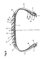
- Fig.9 shows still another embodiment of the present invention.
- the tyre 1 is also a passenger car radial tyre having a relatively low aspect ratio.
- the carcass 6 comprises one ply of cords arranged radially at an angle of from 75 to 90 degrees with respect to the tyre equator C, and turned up around the bead cores in the bead portions to form a pair of turnup portions 6b and a main portion 6a therebetween.
- the belt 7 comprises two radially inner and outer crossed plies whose cords are laid at angles of from 15 to 40 degrees with respect to the tyre equator C.
- steel cords are used as the belt cords to provide a good electrical conductivity.
- the conductive rubber compound 10 is used partially.
- the tread rubber 9 comprises a base tread portion 10 and a cap tread portion 11.
- the base tread portion 10 is disposed radially outside the belt 7 and made of the conductive rubber compound 10 to have a volume resistance of less than about 1X10 8 ohm cm.
- the width of the base tread portion 10 is substantially the same as the width the belt 7. The thickness thereof is substantially constant all over the width.
- the cap tread portion 11 is disposed radially outside the base tread portion so that the radially outer surface defines most of the tread face 2S.
- the width thereof is substantially the same as the base tread portion 10.
- the cap tread portion 11 is made of the same compound as the main part of the tread rubber in the second embodiment. That is, a compound reinforced by mainly silica is used.
- the carbon black contents is preferable about 3 to 20 parts by weight with respect to 100 parts by weight of the diene rubber to fulfil the requirements for the cap tread portion 11 such as elasticity, hardness, heat generation and the like. If the carbon black content exceeds 20 parts by weight, the excellent effect of silica in low rolling resistance decreases and the rubber is liable to lose suppleness. As mentioned above, the upper limit of silica content is 100 parts by weight.
- the cap tread portion 11 is an insulation rubber the volume of which resistance is more than 1X10 8 ohm cm.
- the ratio (h1/h2) of the thickness h1 of the cap tread portion 11 to the thickness h2 of the base tread portion 10 is set in the range of 1.5 to 4.0.
- a circumferentially continuous conductive portion 12 or a plurality of circumferential spaced conductive portions 12 are provided in the ground contacting area 2S.
- the conductive portion 12 extends from the base tread portion 10 to the tread face 2S to penetrate the cap tread portion 11.
- the base tread portion 10 and conductive portions 12 are made of conductive rubber compound having a volume resistance of less than 1X10 8 ohm cm.
- the conductive portion 12 is disposed along the tyre equator C so as to be able to contact the ground with a sufficient ground pressure during cornering as well as straight running.
- a circumferentially continuously extending conductive portion 12 it can be formed as independent poles or columns.
- the cross sectional shape may be formed as a circle, rectangle and the like.
- Such independent conductive portions can be arranged in a circumferential row or rows. Further, a scattered arrangement is also possible. In any case, the arrangement should be such that one or more conductive portions always appear in the ground contacting patch of the tyre.
- the corner between the base tread portion 10 and the conductive portion 12 at the radially inner end 12b thereof is rounded to avoid a stress concentration.
- the axial width Wt of the conductive portion 12 at the outer end 12t or the tread face 2S is preferably set in the range of 0.5 to 20.0 mm or more preferably 5 to 20 mm. If the width Wt is less than 0.5 mm, the electrical contact resistance to the road surface becomes unstable. If the width Wt exceeds 20 mm, the conductive portion 12 is liable to reduce the cap tread portion 11 rolling resistance and wet performance characteristics.
- the conductive portion 12 is provided radially outwards of the inner end 12b with a narrow width part 13 narrower than the inner end 12b.
- the minimum axial width in the narrow width part 13 is preferably in the range of 60 to 80 % of the maximum width Wb at the inner end.
- the narrow width part 13 is formed at the outer end 12t, and the width gradually decreases from the inner end 12b to outer end 12t so that the width becomes a minimum at the tread surface 2S.
- Fig.11 shows another example of the conductive portion 12 in which the narrow width part 13 is formed in the middle of the radial extent of the conductive portion 12.
- the width is increased gradually from the narrow width part 13 to both the outer end 12t and inner end 12b and the outer end 12t and inner end 12b are substantially the same axial width.
- Fig.12 shows a cross section of a strip of raw tread rubber.
- the raw rubber compounds for the cap tread portion, base tread portion and conductive portion are extruded from the dies of a extruder and united in one body as raw tread rubber.
- Such a strip is skived and wound around the circumference of the tyre, and the circumferential ends are spliced.
- 90% or more of the conductive short fibres are oriented in the tyre circumferential direction.
- the base tread portion 10 has a directional elastic modulus such that the complex elastic modulus E*c in the tyre circumferential direction is not less than 1.1 times the complex elastic modulus E*a in the tyre axial direction, whereby the rigidity in the tyre circumferential direction can be increased without sacrificing the ride comfort.
- the tread rubber further includes wing rubbers 15 disposed at the axial ends of the cap tread portion 11 and base tread portion 10.
- the carbon black content of the conductive rubber compound is preferably not more than 35 parts by weight with respect to 100 parts by weight of the rubber base. If the carbon black exceeds 35 parts by weight, the hysteresis loss of the rubber has a tendency to increase.
- the short fibres content is increased enough to provide a sufficient reinforcing effect to the conductive rubber compound, it is possible to decrease the carbon black to substantially zero, which helps to further improve the rolling resistance.
- the silica content is preferably limited to not more than 10 parts by weight. However, it is more preferable to decrease the silica content to zero.
- the carbon black is not limited to a specific sort of carbon black, but carbon black whose particle diameter is not more than 30 nm, that is, hard carbon is preferably used.
- the cap tread portion 11 is reinforced by silica and the base tread portion 10 is reinforced by conductive short fibres and optionally a minimal amount of carbon black. Therefore the hysteresis losses of both the rubbers 10 and 11 are low.
- the rolling resistance can be further decreased while maintaining a good ride comfort.
- the base tread portion 10 is decreased relatively, it is preferable because the heat generation during running is reduced on the inner side of the tyre. It is however more preferable that the cap tread portion 11 is decreased relatively, because the cap tread portion 11 is more effective than the base tread portion 10 on decreasing the rolling resistance. In this example, therefore, the loss tangent of the base tread portion 10 is less than that of the cap tread portion 11.
- the wide conductive base tread portion is disposed at the radially inner end of the conductive portion and extends along the belt, and at least the axial edges of the base tread portion are electrically connected with the sidewall rubber and then bead rubber. Accordingly, it is not always necessary to use a steel belt.
- Pneumatic radial tyres (size: 205/65R15) having the structure shown in Fig.9 were made by way of test using various tread rubber compounds shown in Table 3, and tested for the rolling resistance, electrical resistance and wet performance. The test results are shown in Table 4.
- the bead portions and sidewall portions were made of a rubber compound having a volume resistance of about 1X10 7 ohm cm.
- the base tread portions 5 to 8 were the same complex elastic modulus ratio (E*c/E*a) of 1.1.
- the complex elastic modulus E* and loss tangent are measured with a viscoelastic spectrometer under the following conditions: temperature 70°C, initial elongation 10%, dynamic distortion plus/minus 1%, frequency 10Hz.
Abstract
Description


Claims (17)
- A tyre comprising a tread rubber (2) the radially outer surface of which forms the ground contacting surface (2S) of the tyre, the tread rubber comprising at least partially a conductive rubber extending from the radially inner surface of the tread rubber to the ground contacting surface, characterised in that the conductive rubber is compounded from 100 parts by weight of diene rubber and 2 to 30 parts by weight of conductive short fibres, the conductive short fibres being formed by coating reinforcing short fibres with a conductive substance, and the conductive rubber having a volume resistance of less than 1X10⁸ ohm cm.
- A tyre according to claim 1, characterised in that the length of the conductive short fibres is 10 to 6000 micro meters, and the length/diameter ratio of the conductive short fibres is 10 to 2000.
- A tyre according to claim 1 or 2, characterised in that the reinforcing short fibres are organic fibres, and the conductive substance is one or more of conductive polymers of which the principal chain has pi-electron conjugation.
- A tyre according to claim 3, characterised in that the reinforcing short fibres are a nylon fibre or cellulose fibre, and the conductive substance is a compound each polymer of which has the principal chain made up of pyrrole rings or anilino rings.
- A tyre according to claim 4, characterised in that the conductive substance includes a small quantity of an electron-accepting substance such as iodine, arsenic(V)fluoride and the like, or an electron-donating substance such as potassium, sodium and the like.
- A tyre according to claim 1 or 2, characterised in that the reinforcing short fibres are an organic fibre, and the conductive substance is a metal salt.
- A tyre according to any of claims 1-6, characterised in that substantially the whole of the tread rubber is the conductive rubber.
- A tyre according to any of claims 1-6, characterised in that the tread rubber further comprises a less-conductive rubber and the conductive rubber forms a circumferentially extending conductive part of the ground contacting face, and the less-conductive rubber forms the remaining major part of the ground contacting face.
- A tyre according to any of claims 1-6, characterised in that the tread rubber further comprises a less-conductive rubber, the conductive rubber forms a plurality of circumferentially spaced conductive parts of the ground contacting face, and the less-conductive rubber forms the remaining major part of the ground contacting face.
- A tyre according to any of claims 1-6, characterised in that the tread rubber further comprises a less-conductive rubber, the conductive rubber forms a circumferentially extending conductive part and a plurality of circumferentially spaced conductive parts of the ground contacting face, and the less-conductive rubber forms the remaining major part of the ground contacting face.
- A tyre according to any of claims 8-10, characterised by a steel cord belt (7) disposed immediately inside of the radially inner surface of the tread rubber (2), and the volume of the conductive rubber is 2 to 20 % of the total volume of the tread rubber, and the maximum/minimum ratio of the axial width of the conductive rubber is 1 to about 5.
- A tyre according to claim 11, characterised in that the axial width of the conductive rubber decreases radially outwardly from the radially inner end.
- A tyre according to any of claims 8-10, characterised in that the conductive rubber forms a base tread portion (10) which defines the radially inner surface of the tread rubber, and on which the less-conductive rubber is disposed, and one or more ground-contacting portions (13) extending radially outwardly from the base tread portion to the ground contacting face.
- A tyre according to claim 13, characterised in that said one or more ground-contacting portions (13) are provided on the radially outer side of the radially inner end thereof with a narrow width portion.
- A tyre according to claim 13 or 14, characterised in that the less-conductive rubber is compounded from 100 parts by weight of diene rubber base, 30 to 100 parts by weight of silica, and 3 to 20 parts by weight of carbon black, and the volume resistance thereof is not less than 1X10⁸ ohm cm.
- A tyre according to claim 13, 14 or 15, characterised in that the loss tangent of the conductive rubber in the base tread portion is less than the loss tangent of the less-conductive rubber thereon.
- A tyre according to claim 13, 14, 15 or 16, characterised in that the base tread portion has a directional complex elastic modulus such that the complex elastic modulus E*c in the tyre circumferential direction is not less than 1.1 times the complex elastic modulus E*a in the tyre axial direction.
Applications Claiming Priority (9)
| Application Number | Priority Date | Filing Date | Title |
|---|---|---|---|
| JP12102797 | 1997-05-12 | ||
| JP121027/97 | 1997-05-12 | ||
| JP12102797A JP3734923B2 (en) | 1997-05-12 | 1997-05-12 | Rubber composition for tread and tire using the same |
| JP162892/97 | 1997-06-19 | ||
| JP16289297 | 1997-06-19 | ||
| JP16289297A JP3706461B2 (en) | 1997-06-19 | 1997-06-19 | Pneumatic tire |
| JP35111797 | 1997-12-19 | ||
| JP351117/97 | 1997-12-19 | ||
| JP35111797A JP3898316B2 (en) | 1997-12-19 | 1997-12-19 | Pneumatic tire |
Publications (3)
| Publication Number | Publication Date |
|---|---|
| EP0878330A2 true EP0878330A2 (en) | 1998-11-18 |
| EP0878330A3 EP0878330A3 (en) | 2000-10-18 |
| EP0878330B1 EP0878330B1 (en) | 2003-02-26 |
Family
ID=27314165
Family Applications (1)
| Application Number | Title | Priority Date | Filing Date |
|---|---|---|---|
| EP98303614A Expired - Lifetime EP0878330B1 (en) | 1997-05-12 | 1998-05-08 | Vehicle tyre |
Country Status (3)
| Country | Link |
|---|---|
| US (1) | US6302173B1 (en) |
| EP (1) | EP0878330B1 (en) |
| DE (1) | DE69811560T2 (en) |
Cited By (12)
| Publication number | Priority date | Publication date | Assignee | Title |
|---|---|---|---|---|
| EP0925903A1 (en) * | 1997-12-26 | 1999-06-30 | Bridgestone Corporation | Production of unvulcanized tread rubber for pneumatic tires |
| EP1010553A2 (en) * | 1998-12-17 | 2000-06-21 | Sumitomo Rubber Industries Limited | Pneumatic tyre |
| EP1043178A1 (en) * | 1999-04-09 | 2000-10-11 | Sumitomo Rubber Industries Limited | Pneumatic tyre |
| US6220319B1 (en) * | 1998-10-19 | 2001-04-24 | The Goodyear Tire & Rubber Company | Tire with tread containing electrically conductive staples |
| US6289958B1 (en) * | 1998-10-19 | 2001-09-18 | The Goodyear Tire & Rubber Company | Tire with tread containing electrically conductive stitched thread |
| US6746227B2 (en) | 2001-06-19 | 2004-06-08 | The Goodyear Tire & Rubber Company | Tire tread die |
| EP2193939A1 (en) * | 2007-08-10 | 2010-06-09 | Sumitomo Rubber Industries, Ltd. | Pneumatic tire |
| NL2007544C2 (en) * | 2011-10-06 | 2012-09-25 | Apollo Vredestein Bv | Antistatic vehicle tire and method of manufacturing such a tire. |
| EP2551129A1 (en) * | 2011-07-26 | 2013-01-30 | Toyo Tire & Rubber Co. Ltd. | Pneumatic Tire |
| US8381781B2 (en) | 2007-08-10 | 2013-02-26 | Sumitomo Rubber Industries, Ltd. | Pneumatic tire |
| CN104053561A (en) * | 2012-01-16 | 2014-09-17 | 住友橡胶工业株式会社 | Pneumatic tire and method for manufacturing same |
| EP2596964B1 (en) * | 2011-11-22 | 2017-10-25 | The Goodyear Tire & Rubber Company | Stiffness enhanced tread |
Families Citing this family (22)
| Publication number | Priority date | Publication date | Assignee | Title |
|---|---|---|---|---|
| US7000661B2 (en) * | 2003-06-09 | 2006-02-21 | The Goodyear Tire & Rubber Company | Two-piece tire with improved tire tread belt and carcass |
| KR100542282B1 (en) * | 2003-09-08 | 2006-01-11 | 금호타이어 주식회사 | Rubber composition with silica for improved electric conductivity |
| CN100460231C (en) * | 2003-09-30 | 2009-02-11 | 倍耐力轮胎公司 | Pneumatic tire and process for its manufacture |
| JP2006213193A (en) * | 2005-02-04 | 2006-08-17 | Sumitomo Rubber Ind Ltd | Pneumatic radial-ply tire |
| US20070017617A1 (en) * | 2005-07-22 | 2007-01-25 | Lafrique Michel M | Tire with tread of cap/semibase construction |
| US8800620B2 (en) * | 2006-03-27 | 2014-08-12 | The Goodyear Tire & Rubber Company | Tire with rubber tread composed of a primary and at least one lateral tread portion containing a dispersion of short carbon fibers |
| JP5172686B2 (en) * | 2006-09-27 | 2013-03-27 | 東洋ゴム工業株式会社 | Pneumatic tire |
| US8376005B2 (en) * | 2006-09-27 | 2013-02-19 | Toyo Tire & Rubber Co., Ltd. | Pneumatic tire |
| DE112006004061B4 (en) * | 2006-10-11 | 2021-07-29 | Toyo Tire & Rubber Co., Ltd. | tire |
| WO2008044288A1 (en) * | 2006-10-11 | 2008-04-17 | Toyo Tire & Rubber Co., Ltd. | Pneumatic tire |
| JP4231085B1 (en) * | 2007-10-04 | 2009-02-25 | 株式会社ブリヂストン | Pneumatic tires for motorcycles |
| US20100319827A1 (en) * | 2009-06-19 | 2010-12-23 | Serge Julien Auguste Imhoff | Tire with metallized organic short fibers |
| FR2949998B1 (en) * | 2009-09-15 | 2011-10-07 | Michelin Soc Tech | PNEUMATIC BANDAGE WITH INTEGRATED SELF-SWITCHING LAYER |
| US9878508B2 (en) * | 2010-11-30 | 2018-01-30 | The Goodyear Tire & Rubber Company | Stiffness enhanced tread element |
| JP5367860B2 (en) | 2011-09-29 | 2013-12-11 | 住友ゴム工業株式会社 | Rubber composition for sidewall and tire using the same |
| US10189318B2 (en) * | 2012-09-28 | 2019-01-29 | The Yokohama Rubber Co., Ltd. | Pneumatic tire having specified grounding tread |
| DE112014003404T5 (en) * | 2013-07-24 | 2016-05-25 | The Yokohama Rubber Co., Ltd. | tire |
| WO2016204952A1 (en) * | 2015-06-15 | 2016-12-22 | Bridgestone Americas Tire Operations, Llc | Tire having a conductivity path |
| JP6735176B2 (en) * | 2016-07-29 | 2020-08-05 | Toyo Tire株式会社 | Pneumatic tire |
| JP6768441B2 (en) * | 2016-10-11 | 2020-10-14 | Toyo Tire株式会社 | Pneumatic tires |
| EP3981614A1 (en) * | 2019-06-05 | 2022-04-13 | Sumitomo Rubber Industries, Ltd. | Cord and tire |
| US20230173847A1 (en) * | 2021-12-06 | 2023-06-08 | The Goodyear Tire & Rubber Company | Pneumatic tire having a fiber-reinforced rubber layer and preparation thereof |
Citations (3)
| Publication number | Priority date | Publication date | Assignee | Title |
|---|---|---|---|---|
| EP0356994A1 (en) * | 1988-08-29 | 1990-03-07 | Matsushita Electric Industrial Co., Ltd. | Conductive composition and method of making the same |
| JPH0374202A (en) * | 1989-08-15 | 1991-03-28 | Aichi Tire Kogyo Kk | Static electricity neutralizing tire |
| WO1998040229A1 (en) * | 1997-03-10 | 1998-09-17 | The Goodyear Tire & Rubber Company | Tire with electrically oriented composite |
Family Cites Families (15)
| Publication number | Priority date | Publication date | Assignee | Title |
|---|---|---|---|---|
| US2084523A (en) * | 1935-12-14 | 1937-06-22 | Harry J Crawford | Abrasion resistant grounding device |
| AT316336B (en) * | 1970-08-05 | 1974-07-10 | Semperit Ag | Molded body made of an elastomeric material, and methods and devices for its production |
| FR2110703A5 (en) * | 1970-10-27 | 1972-06-02 | Kleber Colombes | |
| FR2485577A1 (en) * | 1980-06-26 | 1981-12-31 | Rhone Poulenc Textile | TEXTILES WITH IMPROVED CONDUCTIVE PROPERTIES AND PROCESSES FOR THEIR MANUFACTURE |
| US4877646A (en) * | 1988-06-27 | 1989-10-31 | Milliken Research Corporation | Method for making electrically conductive textile materials |
| US5248553A (en) * | 1989-03-16 | 1993-09-28 | Toyo Ink Manufacturing Co., Ltd. | Coated molded article |
| CA2111349C (en) * | 1992-12-14 | 2003-05-06 | Yuichi Saito | Radial tires |
| CA2123828C (en) * | 1993-05-20 | 2001-03-20 | Shingo Midorikawa | Pneumatic vehicle tire |
| JP2640326B2 (en) * | 1993-06-23 | 1997-08-13 | 株式会社ボナール | Anti-static footwear |
| IT1264990B1 (en) * | 1993-12-14 | 1996-10-17 | Pirelli | ANTISTATIC TIRE WITH LOW CARBON BLACK COMPOUNDS |
| US5576104A (en) * | 1994-07-01 | 1996-11-19 | The Goodyear Tire & Rubber Company | Elastomers containing partially oriented reinforcing fibers, tires made using said elastomers, and a method therefor |
| US5518055A (en) * | 1994-09-20 | 1996-05-21 | Michelin Recherche Et Technique S.A. | Low resistivity tire with silica-rich tread and at least one electrostatic discharge ring |
| DE4447823B4 (en) * | 1994-12-21 | 2007-07-26 | Dunlop Gmbh | Vehicle tires and process for its manufacture |
| US6044882A (en) * | 1995-03-07 | 2000-04-04 | The Goodyear Tire & Rubber Company | Tire having silica reinforced rubber tread with outer cap containing carbon black |
| US5718781A (en) * | 1995-06-07 | 1998-02-17 | The Goodyear Tire & Rubber Company | Tire having silica reinforced rubber tread containing carbon fibers |
-
1998
- 1998-05-08 DE DE69811560T patent/DE69811560T2/en not_active Expired - Lifetime
- 1998-05-08 EP EP98303614A patent/EP0878330B1/en not_active Expired - Lifetime
- 1998-05-12 US US09/076,127 patent/US6302173B1/en not_active Expired - Fee Related
Patent Citations (3)
| Publication number | Priority date | Publication date | Assignee | Title |
|---|---|---|---|---|
| EP0356994A1 (en) * | 1988-08-29 | 1990-03-07 | Matsushita Electric Industrial Co., Ltd. | Conductive composition and method of making the same |
| JPH0374202A (en) * | 1989-08-15 | 1991-03-28 | Aichi Tire Kogyo Kk | Static electricity neutralizing tire |
| WO1998040229A1 (en) * | 1997-03-10 | 1998-09-17 | The Goodyear Tire & Rubber Company | Tire with electrically oriented composite |
Non-Patent Citations (1)
| Title |
|---|
| PATENT ABSTRACTS OF JAPAN vol. 015, no. 235 (M-1125), 17 June 1991 (1991-06-17) & JP 03 074202 A (AICHI TIRE KOGYO KK), 28 March 1991 (1991-03-28) * |
Cited By (20)
| Publication number | Priority date | Publication date | Assignee | Title |
|---|---|---|---|---|
| EP0925903A1 (en) * | 1997-12-26 | 1999-06-30 | Bridgestone Corporation | Production of unvulcanized tread rubber for pneumatic tires |
| US6294119B1 (en) | 1997-12-26 | 2001-09-25 | Bridgestone Corporation | Production of unvulcanized tread rubber for pneumatic tires |
| US6220319B1 (en) * | 1998-10-19 | 2001-04-24 | The Goodyear Tire & Rubber Company | Tire with tread containing electrically conductive staples |
| US6289958B1 (en) * | 1998-10-19 | 2001-09-18 | The Goodyear Tire & Rubber Company | Tire with tread containing electrically conductive stitched thread |
| EP1010553A2 (en) * | 1998-12-17 | 2000-06-21 | Sumitomo Rubber Industries Limited | Pneumatic tyre |
| EP1010553A3 (en) * | 1998-12-17 | 2000-11-08 | Sumitomo Rubber Industries Limited | Pneumatic tyre |
| US6343634B1 (en) | 1998-12-17 | 2002-02-05 | Sumitomo Rubber Industries, Ltd. | Pnuematic tire including grounding terminals made of conductive rubber compound |
| EP1043178A1 (en) * | 1999-04-09 | 2000-10-11 | Sumitomo Rubber Industries Limited | Pneumatic tyre |
| US6746227B2 (en) | 2001-06-19 | 2004-06-08 | The Goodyear Tire & Rubber Company | Tire tread die |
| EP2193939A4 (en) * | 2007-08-10 | 2011-03-16 | Sumitomo Rubber Ind | Pneumatic tire |
| EP2193939A1 (en) * | 2007-08-10 | 2010-06-09 | Sumitomo Rubber Industries, Ltd. | Pneumatic tire |
| US8381781B2 (en) | 2007-08-10 | 2013-02-26 | Sumitomo Rubber Industries, Ltd. | Pneumatic tire |
| EP2551129A1 (en) * | 2011-07-26 | 2013-01-30 | Toyo Tire & Rubber Co. Ltd. | Pneumatic Tire |
| US9333812B2 (en) | 2011-07-26 | 2016-05-10 | Toyo Tire & Rubber Co., Ltd. | Pneumatic tire with tread having cap portion, base portion and conductive portion |
| CN104985991B (en) * | 2011-07-26 | 2017-04-12 | 东洋橡胶工业株式会社 | Pneumatic tire |
| NL2007544C2 (en) * | 2011-10-06 | 2012-09-25 | Apollo Vredestein Bv | Antistatic vehicle tire and method of manufacturing such a tire. |
| WO2013051930A1 (en) * | 2011-10-06 | 2013-04-11 | Apollo Vredestein B.V. | Antistatic vehicle tire and method of manufacturing such a tire |
| US9586447B2 (en) | 2011-10-06 | 2017-03-07 | Apollo Tyres Global R&D B.V. | Antistatic vehicle tire and method of manufacturing such a tire |
| EP2596964B1 (en) * | 2011-11-22 | 2017-10-25 | The Goodyear Tire & Rubber Company | Stiffness enhanced tread |
| CN104053561A (en) * | 2012-01-16 | 2014-09-17 | 住友橡胶工业株式会社 | Pneumatic tire and method for manufacturing same |
Also Published As
| Publication number | Publication date |
|---|---|
| EP0878330B1 (en) | 2003-02-26 |
| DE69811560T2 (en) | 2003-08-28 |
| EP0878330A3 (en) | 2000-10-18 |
| US6302173B1 (en) | 2001-10-16 |
| DE69811560D1 (en) | 2003-04-03 |
Similar Documents
| Publication | Publication Date | Title |
|---|---|---|
| EP0878330B1 (en) | Vehicle tyre | |
| US6269854B1 (en) | Pneumatic tire including discharge terminal parts | |
| JP3964511B2 (en) | Pneumatic tire | |
| US7284582B2 (en) | Pneumatic tire with electrically conductive cord extending between a bead portion and a tread portion of the tire | |
| US7284583B2 (en) | Pneumatic tire with electrically conductive cord extending from its outer wheel-rim mounting surface to its internal tread portion | |
| CA1113357A (en) | Radial-ply tire | |
| CN103857542B (en) | Air-inflation tyre | |
| CN103205031B (en) | Rubber composition for tire and pneumatic tire | |
| JP5344098B1 (en) | Pneumatic tire | |
| US20050103412A1 (en) | Tire with rubber sidewall containing internal electrically conductive rubber strip | |
| EP0159469A1 (en) | Tire tread compound | |
| AU2005209668A1 (en) | Tire with puncture resistant sidewall | |
| EP1006007B1 (en) | Studless tyre | |
| CN102421611B (en) | Pneumatic tire | |
| JP4392068B2 (en) | Pneumatic tire | |
| JP3898316B2 (en) | Pneumatic tire | |
| WO2004056586A1 (en) | Tyre for two-wheeled vehicles | |
| US4360049A (en) | Radial tires having improved irregular wear resistance | |
| JP3706461B2 (en) | Pneumatic tire | |
| JP2000079805A (en) | Pneumatic tire | |
| EP0435620A1 (en) | A radial tyre for a passenger car | |
| JP2007331529A (en) | Pneumatic tire | |
| JP4071895B2 (en) | Pneumatic tire | |
| JP3734923B2 (en) | Rubber composition for tread and tire using the same | |
| US20200307317A1 (en) | Tire |
Legal Events
| Date | Code | Title | Description |
|---|---|---|---|
| PUAI | Public reference made under article 153(3) epc to a published international application that has entered the european phase |
Free format text: ORIGINAL CODE: 0009012 |
|
| AK | Designated contracting states |
Kind code of ref document: A2 Designated state(s): DE FR GB |
|
| AX | Request for extension of the european patent |
Free format text: AL;LT;LV;MK;RO;SI |
|
| PUAL | Search report despatched |
Free format text: ORIGINAL CODE: 0009013 |
|
| AK | Designated contracting states |
Kind code of ref document: A3 Designated state(s): AT BE CH CY DE DK ES FI FR GB GR IE IT LI LU MC NL PT SE |
|
| AX | Request for extension of the european patent |
Free format text: AL;LT;LV;MK;RO;SI |
|
| 17P | Request for examination filed |
Effective date: 20010226 |
|
| AKX | Designation fees paid |
Free format text: DE FR GB |
|
| GRAH | Despatch of communication of intention to grant a patent |
Free format text: ORIGINAL CODE: EPIDOS IGRA |
|
| GRAH | Despatch of communication of intention to grant a patent |
Free format text: ORIGINAL CODE: EPIDOS IGRA |
|
| GRAA | (expected) grant |
Free format text: ORIGINAL CODE: 0009210 |
|
| AK | Designated contracting states |
Designated state(s): DE FR GB |
|
| REG | Reference to a national code |
Ref country code: GB Ref legal event code: FG4D |
|
| REF | Corresponds to: |
Ref document number: 69811560 Country of ref document: DE Date of ref document: 20030403 Kind code of ref document: P |
|
| ET | Fr: translation filed | ||
| PLBE | No opposition filed within time limit |
Free format text: ORIGINAL CODE: 0009261 |
|
| STAA | Information on the status of an ep patent application or granted ep patent |
Free format text: STATUS: NO OPPOSITION FILED WITHIN TIME LIMIT |
|
| 26N | No opposition filed |
Effective date: 20031127 |
|
| PGFP | Annual fee paid to national office [announced via postgrant information from national office to epo] |
Ref country code: GB Payment date: 20100329 Year of fee payment: 13 |
|
| PGFP | Annual fee paid to national office [announced via postgrant information from national office to epo] |
Ref country code: FR Payment date: 20100525 Year of fee payment: 13 |
|
| PGFP | Annual fee paid to national office [announced via postgrant information from national office to epo] |
Ref country code: DE Payment date: 20100512 Year of fee payment: 13 |
|
| REG | Reference to a national code |
Ref country code: DE Ref legal event code: R119 Ref document number: 69811560 Country of ref document: DE |
|
| REG | Reference to a national code |
Ref country code: DE Ref legal event code: R119 Ref document number: 69811560 Country of ref document: DE |
|
| GBPC | Gb: european patent ceased through non-payment of renewal fee |
Effective date: 20110508 |
|
| REG | Reference to a national code |
Ref country code: FR Ref legal event code: ST Effective date: 20120131 |
|
| PG25 | Lapsed in a contracting state [announced via postgrant information from national office to epo] |
Ref country code: FR Free format text: LAPSE BECAUSE OF NON-PAYMENT OF DUE FEES Effective date: 20110531 |
|
| PG25 | Lapsed in a contracting state [announced via postgrant information from national office to epo] |
Ref country code: GB Free format text: LAPSE BECAUSE OF NON-PAYMENT OF DUE FEES Effective date: 20110508 |
|
| PG25 | Lapsed in a contracting state [announced via postgrant information from national office to epo] |
Ref country code: DE Free format text: LAPSE BECAUSE OF NON-PAYMENT OF DUE FEES Effective date: 20111130 |