EP0876916A2 - Ink jet recording head - Google Patents
Ink jet recording head Download PDFInfo
- Publication number
- EP0876916A2 EP0876916A2 EP98108244A EP98108244A EP0876916A2 EP 0876916 A2 EP0876916 A2 EP 0876916A2 EP 98108244 A EP98108244 A EP 98108244A EP 98108244 A EP98108244 A EP 98108244A EP 0876916 A2 EP0876916 A2 EP 0876916A2
- Authority
- EP
- European Patent Office
- Prior art keywords
- electro
- ink jet
- thermal transducers
- thickness
- recording head
- Prior art date
- Legal status (The legal status is an assumption and is not a legal conclusion. Google has not performed a legal analysis and makes no representation as to the accuracy of the status listed.)
- Granted
Links
Images


Classifications
-
- B—PERFORMING OPERATIONS; TRANSPORTING
- B41—PRINTING; LINING MACHINES; TYPEWRITERS; STAMPS
- B41J—TYPEWRITERS; SELECTIVE PRINTING MECHANISMS, i.e. MECHANISMS PRINTING OTHERWISE THAN FROM A FORME; CORRECTION OF TYPOGRAPHICAL ERRORS
- B41J2/00—Typewriters or selective printing mechanisms characterised by the printing or marking process for which they are designed
- B41J2/005—Typewriters or selective printing mechanisms characterised by the printing or marking process for which they are designed characterised by bringing liquid or particles selectively into contact with a printing material
- B41J2/01—Ink jet
- B41J2/135—Nozzles
- B41J2/14—Structure thereof only for on-demand ink jet heads
- B41J2/14016—Structure of bubble jet print heads
- B41J2/14032—Structure of the pressure chamber
- B41J2/14056—Plural heating elements per ink chamber
-
- B—PERFORMING OPERATIONS; TRANSPORTING
- B41—PRINTING; LINING MACHINES; TYPEWRITERS; STAMPS
- B41J—TYPEWRITERS; SELECTIVE PRINTING MECHANISMS, i.e. MECHANISMS PRINTING OTHERWISE THAN FROM A FORME; CORRECTION OF TYPOGRAPHICAL ERRORS
- B41J2/00—Typewriters or selective printing mechanisms characterised by the printing or marking process for which they are designed
- B41J2/005—Typewriters or selective printing mechanisms characterised by the printing or marking process for which they are designed characterised by bringing liquid or particles selectively into contact with a printing material
- B41J2/01—Ink jet
- B41J2/135—Nozzles
- B41J2/14—Structure thereof only for on-demand ink jet heads
- B41J2/14016—Structure of bubble jet print heads
- B41J2/14088—Structure of heating means
- B41J2/14112—Resistive element
- B41J2/14129—Layer structure
Definitions
- the present invention relates to an ink jet recording head, and more particularly, to a so-called gradation-controllable ink jet head in which a plurality of electro-thermal transducers are arranged on respective nozzles for ejecting ink droplets, whereby the amount of the ejected ink droplets can be changed in accordance with image data.
- the piezoelectric system can control the amount of the ejected ink droplets within a relatively wide range by modulating a driving waveform of the piezoelectric element, and is suitable for controlling gradation.
- the piezoelectric element since the piezoelectric element is utilized, the manufacturing process thereof becomes complicated and the system is not so suitable for a high-density arrangement of nozzles.
- the bubble jet system has high productivity and excellent high-density arrangement of the nozzles as compared with the above piezoelectric system, and is suitable for producing a high-speed ink jet head at a low cost. It is difficult, however, for the bubble jet system to modulate the amount of the ejected ink droplets.
- a multi-level system has been proposed in which the density of the nozzle arrangement is increased, the amount of the ejected ink droplets is decreased to, for example, about 10 picoliters, and one pixel is represented by many dots.
- the multilevel system encounters the following problems. Since the pixel is constituted by fine ink droplets as described above, the number of droplets-driving pulses increases in accordance with the number of dots, thereby shortening the life of the ink jet head. In addition, at the head driving frequency which is the same as that of the conventional head, the recording speed is decreased.
- an ink jet head in which a plurality of electro-thermal transducers are arranged in one nozzle, and the electro-thermal transducers are actuated as needed, thereby changing the amount of the ejected ink droplets.
- Fig. 3 shows a cross-sectional configuration of the portion of the electro-thermal transducer taken along the line A-A' of Fig. 2.
- a resistive layer 4 formed by a resistor material, such as HfB 2 , a wiring layer S formed of Al, and a protective layer 6 formed of insulating material, such as SiO 2 are formed on a silicon substrate having a heat storage layer formed thereon. Although a cavitation resistant layer and a protective layer, etc. are further formed thereon, they are omitted from the drawing.
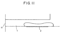
- the ink jet head in which a plurality of electro-thermal transducers 2 are arranged in one nozzle 1, it is possible to actuate a necessary electro-thermal transducer 2 and to change the volume of an air-bubble in accordance with a necessary amount of ejection in order to change the heat generating area of the electro-thermal transducer 2.
- the nozzle 1 ejecting the ink droplets is, however, common to each of the electro-thermal transducers 2. Therefore, it is difficult to optimally design the nozzle 1 corresponding to individual amounts of ejection. Particularly, since an ejection port 11 of the tip of the nozzle 1 is fixed, it is almost impossible to optimize the amount of ejection and ejection speed simultaneously.
- the position of the electro-thermal transducers may be changed. This is intended to obtain a necessary amount of ejection and ejection speed by optimizing each of the center points of air bubbles in the electro-thermal transducers.
- Fig. 10 shows the relationship between the ejection speed and the amount of ejection when the center of gravity of the electro-thermal transducer is changed. More specifically, Fig. 10 shows the amount of ejection and the ejection speed when a small-area heater and a large-area heater of the electro-thermal transducer are actuated singly and in combination.
- the center of gravity of the electro-thermal transducer in relation to the position of the nozzle is a large determinant of the amount of ejection and the ejection speed.
- the entire length of the nozzle should be short to some extent.
- Fig. 2 for example, two electro-thermal transducers 2 are arranged in one nozzle 1 so as to obtain the ejection amounts of 40 picoliters and 80 picoliters.
- an area of about 2000 square microns is required, and an area of about 4000 square microns is required in order to achieve an ejection amount of 80 picoliters, although they are depend on the driving condition of the electro-thermal transducers 2.
- the width of the heater is defined due to the restriction in size, so that the length of the heater is also defined.
- the heaters having a size of 16 ⁇ x 125 ⁇ , and a size of 22 ⁇ x 178 ⁇ are required, respectively.
- Fig. 11 illustrates the above-described arrangement of the electro-thermal transducers.
- an ink jet recording head of high printing quality including a plurality of electro-thermal transducers provided on a substrate corresponding to respective nozzles, wherein the relationship between the amount and the speed of ejected ink droplets can be optimized in accordance with the size of areas of the electro-thermal transducers.
- an ink jet recording head including a plurality of electro-thermal transducers arranged on a substrate corresponding to respective nozzles, wherein each protective layer placed on a resistor constituting each of the plurality of electro-thermal transducers has a thickness-reduced portion at a part thereof so as to increase the distance between the center point of the air bubble of each of the plurality of electro-thermal transducers to longer than the distance between the centers of gravity of each of the plurality of electro-thermal transducers.
- the plurality of electro-thermal transducers may be arranged in parallel with, or in line with each other, and each of the thickness-reduced portions is placed at a position shifted from the center of gravity of the resistor to increase the distance therebetween.
- the thickness-reduced portion of a small-area heater may be located on the side of an ejection port which is placed forward of the center of gravity of the resistor, and the thickness-reduced portion of a large-area heater may be located rearward of the center of gravity of the resistor, thereby optimizing the relationship between the amount and the speed of the ejected ink droplets in accordance with the size of areas of the electro-thermal transducers.
- the thickness-reduced portion may be arranged or shaped so as to avoid a cavitation portion which occurs during debubbling.
- the present invention is configured as described above. More specifically, a partial reduction in thickness of the protective layer constituting the electro-thermal transducer moves the point of action of an air bubble to the forward or rearward of the center of the electro-thermal transducer, thereby making it possible to increase the difference in distribution ratios of flow resistance of nozzles forward and rearward of respective points of action of the air bubble of a plurality of electro-thermal transducers to higher than the difference in distribution ratios of flow resistance of nozzles forward and rearward of respective centers of gravity.
- the point of action of the air bubble of the small-area heater can be placed in a more forward position, and the point of action of the air bubble of the large-area heater can be placed in a more rearward position.
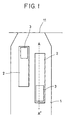
- Fig. 1 shows a first embodiment of the present invention.
- electro-thermal transducers 2 are arranged in parallel with each other in a nozzle 1 of an ink jet head.
- a cross-sectional configuration of the electro-thermal transducer 2 taken along the line A-A' is shown in Fig. 4.
- a protective layer 6 has a thickness-reduced portion 3 provided on a part of the upper surface of a resistive layer 4.
- Such a thickness-reduced portion 3 is formed by etching again only the portion to be reduced in thickness after the patterning of the protective layer 6 in a substrate-manufacturing step.
- the partial reduction in thickness of the protective layer 6 produces an air bubble 8 at the thickness-reduced portion 3 of the protective layer 6 earlier than a thick portion.
- the air bubble 8 grows around the thickness-reduced portion 3, and finally spreads over the entire effective surface of the electro-thermal transducer.
- the point of action (center) of the air bubble 8 can be moved to the side of a thin layer region and a necessary air bubble volume can be obtained. This allows the center of the air bubble to be located forward or rearward from the actual position where the electro-thermal transducers 2 are arranged, thereby achieving a more preferable relationship from the design viewpoint between the amount of ejection and ejection speed due to the change of the center of gravity of the electro-thermal transducer shown in Fig. 10.
- the thickness-reduced portion 3 of the electro-thermal transducer 2 located forward of the nozzle 1 is placed on the side of an ejection port 11, thereby reducing the amount of ejected ink droplets and increasing the ejection speed.
- the thickness-reduced portion 3 on the electro-thermal transducer 2 located rearward of the nozzle 1 is placed in rearward of the nozzle 1, thereby preventing an excessive increase in the ejection speed while securing a large amount of the ejected ink droplets.
- the ejection speed of small droplets which are ejected in small amounts is increased to higher than that of small droplets ejected from the conventional ink jet head, resulting in the achievement of an operation with a high degree of reliability.
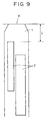
- Fig. 6 shows a second embodiment of the present invention.
- electro-thermal transducers 2 are arranged in series in the nozzle 1 of the ink jet head 1.
- the thickness-reduced portion 3 is provided on the electro-thermal transducer 2 located on the rearward position of the nozzle 1 so as to prevent an excessive increase in the ejection speed while securing a large amount of ejection.
- the thickness-reduced portion 3 may be provided on both of the electro-thermal transducers 2.
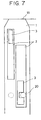
- Fig. 7 shows a third embodiment of the present invention.
- a cavitation occurs during debubbling as shown in Fig. 8, and a shock wave strikes the surface of the protective layer to gradually damage the protective layer.
- the protective layer is broken, the wiring layer is exposed to cause electrolytic corrosion, and eventually the ink jet head is broken.
- a cavitation-concentrating portion 20 is avoided, the position of the thickness-reduced portion 3 or the shape thereof is contrived so as to be unaffected by the cavitation.
- the relationship between the amount and the speed of the ejected ink droplets can be optimized in accordance with the size of the areas of the electro-thermal transducers. More particularly, a thickness-reduced portion of the protective layer is located forward of the center of the electro-thermal transducer, whereby the ejection speed of the ink droplets is increased and the reliability thereof is increased in the small-area heater, and the thickness-reduced portion is located rearward of the center of the electro-thermal transducer so that the ejection speed is decreased and excessive ejection energy is prevented in the large-area heater, thereby enabling the formation of a normal image and the realization of an ink jet recording head of high printing quality.
- the position of the thickness-reduced portion, or the shape thereof is contrived, whereby a cavitation-concentrating portion can be avoided.
- temperatures can be controlled in more precisely. Still further, by selectively actuating a heat preserving heater as needed, the temperatures can be controlled in more precisely, so that image quality can be increased, unevenness of density can be prevented, and operation reliability can be increased.
- An ink jet recording head of high printing quality including a plurality of electro-thermal transducers arranged on a substrate corresponding to respective nozzles, wherein each protective layer placed on a resistor constituting each of the plurality of electro-thermal transducers has a thickness-reduced portion at a part thereof so as to increase the distance between the center point of the air bubble of each of the plurality of electro-thermal transducers to longer than the distance between the centers of gravity of each of the plurality of electro-thermal transducers.
Abstract
Description
Claims (5)
- An ink jet recording head comprising a plurality of electro-thermal transducers arranged on a substrate corresponding to respective nozzles, wherein each protective layer placed on a resistor constituting each of said plurality of electro-thermal transducers has a thickness-reduced portion at a part thereof so as to increase the distance between the center point of the air bubble of each of said plurality of electro-thermal transducers to longer than the distance between the centers of gravity of each of said plurality of electro-thermal transducers.
- An ink jet recording head according to claim 1, wherein said plurality of electro-thermal transducers are arranged in parallel with each other, and each of said thickness-reduced portions is placed at a position shifted from the center of gravity of said resistor to increase the distance therebetween.
- An ink jet recording head according to claim 1, wherein said plurality of electro-thermal transducers are arranged in line with each other, and each of said thickness-reduced portions is placed at a position shifted from the center of gravity of said resistor to increase the distance therebetween.
- An ink jet recording head according to any one of claims 1 to 3, wherein said thickness-reduced portion of a small-area heater is located on the side of an ejection port which is placed forward of the center of gravity of said resistor, and said thickness-reduced portion of a large-area heater is located rearward of the center of gravity of said resistor.
- An ink jet recording head according to any one of claims 1 to 4, wherein said thickness-reduced portion is arranged or shaped so as to avoid a cavitation portion which occurs during debubbling.
Applications Claiming Priority (3)
| Application Number | Priority Date | Filing Date | Title |
|---|---|---|---|
| JP13288997 | 1997-05-07 | ||
| JP132889/97 | 1997-05-07 | ||
| JP13288997A JP3501619B2 (en) | 1997-05-07 | 1997-05-07 | Inkjet recording head |
Publications (3)
| Publication Number | Publication Date |
|---|---|
| EP0876916A2 true EP0876916A2 (en) | 1998-11-11 |
| EP0876916A3 EP0876916A3 (en) | 2000-03-15 |
| EP0876916B1 EP0876916B1 (en) | 2004-03-03 |
Family
ID=15091929
Family Applications (1)
| Application Number | Title | Priority Date | Filing Date |
|---|---|---|---|
| EP98108244A Expired - Lifetime EP0876916B1 (en) | 1997-05-07 | 1998-05-06 | Ink jet recording head |
Country Status (4)
| Country | Link |
|---|---|
| US (1) | US6224191B1 (en) |
| EP (1) | EP0876916B1 (en) |
| JP (1) | JP3501619B2 (en) |
| DE (1) | DE69822031T2 (en) |
Cited By (2)
| Publication number | Priority date | Publication date | Assignee | Title |
|---|---|---|---|---|
| EP1195253A1 (en) * | 1999-07-12 | 2002-04-10 | Copyer Co., Ltd. | Ink jet system image forming device |
| US6988786B2 (en) * | 2002-04-23 | 2006-01-24 | Canon Kabushiki Kaisha | Ink jet recording head and ink discharge method |
Families Citing this family (11)
| Publication number | Priority date | Publication date | Assignee | Title |
|---|---|---|---|---|
| US6799838B2 (en) * | 1998-08-31 | 2004-10-05 | Canon Kabushiki Kaisha | Liquid discharge head liquid discharge method and liquid discharge apparatus |
| JP2002187261A (en) * | 2000-10-10 | 2002-07-02 | Canon Inc | Ink jet recording device |
| JP2004001488A (en) * | 2002-04-23 | 2004-01-08 | Canon Inc | Inkjet head |
| JP2004001490A (en) * | 2002-04-23 | 2004-01-08 | Canon Inc | Inkjet head |
| US6802588B2 (en) * | 2002-08-26 | 2004-10-12 | Eastman Kodak Company | Fluid jet apparatus and method for cleaning inkjet printheads |
| US7207666B2 (en) * | 2003-08-07 | 2007-04-24 | Hewlett-Packard Development Company, L.P. | Printer ink supply system |
| JP2005184903A (en) * | 2003-12-17 | 2005-07-07 | Seiko Epson Corp | Electrostatic actuator, droplet ejection head and droplet ejection device |
| US7172268B2 (en) * | 2003-12-26 | 2007-02-06 | Canon Kabushiki Kaisha | Ink jet head, method for driving the same, and ink jet recording apparatus |
| US7195343B2 (en) * | 2004-08-27 | 2007-03-27 | Lexmark International, Inc. | Low ejection energy micro-fluid ejection heads |
| JP4553360B2 (en) * | 2004-12-24 | 2010-09-29 | キヤノン株式会社 | Inkjet recording head |
| JP4926691B2 (en) * | 2006-12-21 | 2012-05-09 | キヤノン株式会社 | Ink jet recording head and method of manufacturing ink jet recording head |
Citations (5)
| Publication number | Priority date | Publication date | Assignee | Title |
|---|---|---|---|---|
| EP0350953A2 (en) * | 1988-07-15 | 1990-01-17 | Canon Kabushiki Kaisha | Substrate for liquid jet recording head and liquid jet recording head provided with said substrate |
| EP0707964A2 (en) * | 1994-10-20 | 1996-04-24 | Canon Kabushiki Kaisha | Liquid jet head, head cartridge, liquid jet apparatus, method of ejecting liquid, and method of injecting ink |
| EP0747221A2 (en) * | 1995-06-06 | 1996-12-11 | Canon Kabushiki Kaisha | Ink jet head, ink jet apparatus and ink jet recording method |
| EP0750991A2 (en) * | 1995-06-30 | 1997-01-02 | Canon Kabushiki Kaisha | Ink-jet recording head and ink-jet recording apparatus |
| US5600356A (en) * | 1989-07-25 | 1997-02-04 | Ricoh Company, Ltd. | Liquid jet recording head having improved radiator member |
Family Cites Families (7)
| Publication number | Priority date | Publication date | Assignee | Title |
|---|---|---|---|---|
| DE2945658A1 (en) * | 1978-11-14 | 1980-05-29 | Canon Kk | LIQUID JET RECORDING METHOD |
| US4587534A (en) | 1983-01-28 | 1986-05-06 | Canon Kabushiki Kaisha | Liquid injection recording apparatus |
| JPS6334144A (en) * | 1986-07-29 | 1988-02-13 | Canon Inc | Liquid jet recording head |
| JPS63160853A (en) * | 1986-12-25 | 1988-07-04 | Canon Inc | Liquid jet recording head |
| JP2662446B2 (en) | 1989-12-11 | 1997-10-15 | キヤノン株式会社 | Printhead and printhead element substrate |
| DE69122726T2 (en) | 1990-12-12 | 1997-03-13 | Canon Kk | Inkjet recording |
| US5479197A (en) | 1991-07-11 | 1995-12-26 | Canon Kabushiki Kaisha | Head for recording apparatus |
-
1997
- 1997-05-07 JP JP13288997A patent/JP3501619B2/en not_active Expired - Fee Related
-
1998
- 1998-04-28 US US09/066,864 patent/US6224191B1/en not_active Expired - Fee Related
- 1998-05-06 EP EP98108244A patent/EP0876916B1/en not_active Expired - Lifetime
- 1998-05-06 DE DE69822031T patent/DE69822031T2/en not_active Expired - Fee Related
Patent Citations (5)
| Publication number | Priority date | Publication date | Assignee | Title |
|---|---|---|---|---|
| EP0350953A2 (en) * | 1988-07-15 | 1990-01-17 | Canon Kabushiki Kaisha | Substrate for liquid jet recording head and liquid jet recording head provided with said substrate |
| US5600356A (en) * | 1989-07-25 | 1997-02-04 | Ricoh Company, Ltd. | Liquid jet recording head having improved radiator member |
| EP0707964A2 (en) * | 1994-10-20 | 1996-04-24 | Canon Kabushiki Kaisha | Liquid jet head, head cartridge, liquid jet apparatus, method of ejecting liquid, and method of injecting ink |
| EP0747221A2 (en) * | 1995-06-06 | 1996-12-11 | Canon Kabushiki Kaisha | Ink jet head, ink jet apparatus and ink jet recording method |
| EP0750991A2 (en) * | 1995-06-30 | 1997-01-02 | Canon Kabushiki Kaisha | Ink-jet recording head and ink-jet recording apparatus |
Cited By (5)
| Publication number | Priority date | Publication date | Assignee | Title |
|---|---|---|---|---|
| EP1195253A1 (en) * | 1999-07-12 | 2002-04-10 | Copyer Co., Ltd. | Ink jet system image forming device |
| EP1195253A4 (en) * | 1999-07-12 | 2002-10-09 | Copyer Co | Ink jet system image forming device |
| US6988786B2 (en) * | 2002-04-23 | 2006-01-24 | Canon Kabushiki Kaisha | Ink jet recording head and ink discharge method |
| US7172264B2 (en) | 2002-04-23 | 2007-02-06 | Canon Kabushiki Kaisha | Ink jet recording heat and ink discharge method |
| US7527352B2 (en) | 2002-04-23 | 2009-05-05 | Canon Kabushiki Kaisha | Ink jet recording head and ink discharge method |
Also Published As
| Publication number | Publication date |
|---|---|
| DE69822031D1 (en) | 2004-04-08 |
| EP0876916B1 (en) | 2004-03-03 |
| JP3501619B2 (en) | 2004-03-02 |
| US6224191B1 (en) | 2001-05-01 |
| DE69822031T2 (en) | 2005-01-27 |
| JPH10305579A (en) | 1998-11-17 |
| EP0876916A3 (en) | 2000-03-15 |
Similar Documents
| Publication | Publication Date | Title |
|---|---|---|
| EP0876916B1 (en) | Ink jet recording head | |
| US7090334B2 (en) | Ink jet record head | |
| KR100977645B1 (en) | Liquid jet head | |
| US6227640B1 (en) | Variable drop mass inkjet drop generator | |
| EP1232867B1 (en) | Electrical circuit for wide-array inkjet printhead assembly | |
| KR20020071741A (en) | Printer head, printer and the driving method of printer head | |
| US20070023389A1 (en) | Substrate and method of forming substrate for fluid ejection device | |
| US6974548B2 (en) | Printhead having a thin film membrane with a floating section | |
| KR100335589B1 (en) | Substrate for use of ink jet head, ink jet head, ink jet cartridge, and ink jet recording apparatus | |
| JP2004230885A (en) | Ink jet recording head | |
| US6648451B2 (en) | Ink jet recording apparatus and ink jet recording head | |
| EP0461939B1 (en) | Ink jet recording apparatus using heat generating element | |
| US6782621B2 (en) | Method of fabricating a fluid ejector | |
| US5898448A (en) | Ink ejecting device having ink chambers of differing shapes | |
| JP3127663B2 (en) | Ink jet recording apparatus and recording method | |
| JP2001180015A (en) | Ink jet recorder, ink jet recording method, and ink jet recording head | |
| EP0807522B1 (en) | Inkjet recording head and inkjet apparatus provided with the same | |
| JP4757050B2 (en) | Inkjet recording head and inkjet recording method | |
| JP2001030512A (en) | Ink-jet recording apparatus and method for recovering discharge in the apparatus | |
| JP4039955B2 (en) | Substrate for fluid ejection device and method of forming substrate | |
| JP2007301937A (en) | Recording head and board for the recording head | |
| JP2004306417A (en) | Image formation device and image formation method | |
| JPH1044413A (en) | Ink jet recording head | |
| JPH05286134A (en) | Ink jet recording head | |
| JPH09150515A (en) | Ink jet head |
Legal Events
| Date | Code | Title | Description |
|---|---|---|---|
| PUAI | Public reference made under article 153(3) epc to a published international application that has entered the european phase |
Free format text: ORIGINAL CODE: 0009012 |
|
| AK | Designated contracting states |
Kind code of ref document: A2 Designated state(s): DE ES FR GB IT NL |
|
| AX | Request for extension of the european patent |
Free format text: AL;LT;LV;MK;RO;SI |
|
| PUAL | Search report despatched |
Free format text: ORIGINAL CODE: 0009013 |
|
| AK | Designated contracting states |
Kind code of ref document: A3 Designated state(s): AT BE CH CY DE DK ES FI FR GB GR IE IT LI LU MC NL PT SE |
|
| AX | Request for extension of the european patent |
Free format text: AL;LT;LV;MK;RO;SI |
|
| 17P | Request for examination filed |
Effective date: 20000728 |
|
| AKX | Designation fees paid |
Free format text: DE ES FR GB IT NL |
|
| GRAH | Despatch of communication of intention to grant a patent |
Free format text: ORIGINAL CODE: EPIDOS IGRA |
|
| GRAS | Grant fee paid |
Free format text: ORIGINAL CODE: EPIDOSNIGR3 |
|
| GRAA | (expected) grant |
Free format text: ORIGINAL CODE: 0009210 |
|
| AK | Designated contracting states |
Kind code of ref document: B1 Designated state(s): DE ES FR GB IT NL |
|
| PG25 | Lapsed in a contracting state [announced via postgrant information from national office to epo] |
Ref country code: NL Free format text: LAPSE BECAUSE OF FAILURE TO SUBMIT A TRANSLATION OF THE DESCRIPTION OR TO PAY THE FEE WITHIN THE PRESCRIBED TIME-LIMIT Effective date: 20040303 |
|
| REG | Reference to a national code |
Ref country code: GB Ref legal event code: FG4D |
|
| REF | Corresponds to: |
Ref document number: 69822031 Country of ref document: DE Date of ref document: 20040408 Kind code of ref document: P |
|
| PG25 | Lapsed in a contracting state [announced via postgrant information from national office to epo] |
Ref country code: ES Free format text: LAPSE BECAUSE OF FAILURE TO SUBMIT A TRANSLATION OF THE DESCRIPTION OR TO PAY THE FEE WITHIN THE PRESCRIBED TIME-LIMIT Effective date: 20040614 |
|
| NLV1 | Nl: lapsed or annulled due to failure to fulfill the requirements of art. 29p and 29m of the patents act | ||
| ET | Fr: translation filed | ||
| PLBE | No opposition filed within time limit |
Free format text: ORIGINAL CODE: 0009261 |
|
| STAA | Information on the status of an ep patent application or granted ep patent |
Free format text: STATUS: NO OPPOSITION FILED WITHIN TIME LIMIT |
|
| 26N | No opposition filed |
Effective date: 20041206 |
|
| PGFP | Annual fee paid to national office [announced via postgrant information from national office to epo] |
Ref country code: DE Payment date: 20080531 Year of fee payment: 11 |
|
| PGFP | Annual fee paid to national office [announced via postgrant information from national office to epo] |
Ref country code: IT Payment date: 20080520 Year of fee payment: 11 |
|
| PGFP | Annual fee paid to national office [announced via postgrant information from national office to epo] |
Ref country code: GB Payment date: 20080520 Year of fee payment: 11 |
|
| GBPC | Gb: european patent ceased through non-payment of renewal fee |
Effective date: 20090506 |
|
| REG | Reference to a national code |
Ref country code: FR Ref legal event code: ST Effective date: 20100129 |
|
| PG25 | Lapsed in a contracting state [announced via postgrant information from national office to epo] |
Ref country code: FR Free format text: LAPSE BECAUSE OF NON-PAYMENT OF DUE FEES Effective date: 20090602 |
|
| PGFP | Annual fee paid to national office [announced via postgrant information from national office to epo] |
Ref country code: FR Payment date: 20080424 Year of fee payment: 11 |
|
| PG25 | Lapsed in a contracting state [announced via postgrant information from national office to epo] |
Ref country code: GB Free format text: LAPSE BECAUSE OF NON-PAYMENT OF DUE FEES Effective date: 20090506 |
|
| PG25 | Lapsed in a contracting state [announced via postgrant information from national office to epo] |
Ref country code: DE Free format text: LAPSE BECAUSE OF NON-PAYMENT OF DUE FEES Effective date: 20091201 |
|
| PG25 | Lapsed in a contracting state [announced via postgrant information from national office to epo] |
Ref country code: IT Free format text: LAPSE BECAUSE OF NON-PAYMENT OF DUE FEES Effective date: 20090506 |